lga771 socket - intel | data center solutions, iot, and … intel® xeon® processor 5000 series...
TRANSCRIPT

Reference Number: 313871-002
LGA771 SocketMechanical Design Guide
November, 2006

2 LGA 771 Socket Mechanical Design Guide
INFORMATION IN THIS DOCUMENT IS PROVIDED IN CONNECTION WITH INTEL® PRODUCTS. NO LICENSE, EXPRESS OR IMPLIED, BY ESTOPPEL OR OTHERWISE, TO ANY INTELLECTUAL PROPERTY RIGHTS IS GRANTED BY THIS DOCUMENT. EXCEPT AS PROVIDED IN INTEL'S TERMS AND CONDITIONS OF SALE FOR SUCH PRODUCTS, INTEL ASSUMES NO LIABILITY WHATSOEVER, AND INTEL DISCLAIMS ANY EXPRESS OR IMPLIED WARRANTY, RELATING TO SALE AND/OR USE OF INTEL PRODUCTS INCLUDING LIABILITY OR WARRANTIES RELATING TO FITNESS FOR A PARTICULAR PURPOSE, MERCHANTABILITY, OR INFRINGEMENT OF ANY PATENT, COPYRIGHT OR OTHER INTELLECTUAL PROPERTY RIGHT. Intel products are not intended for use in medical, life saving, or life sustaining applications.
Intel may make changes to specifications and product descriptions at any time, without notice.
Designers must not rely on the absence or characteristics of any features or instructions marked “reserved” or “undefined.” Intel reserves these for future definition and shall have no responsibility whatsoever for conflicts or incompatibilities arising from future changes to them.
The LGA 771 socket may contain design defects or errors known as errata which may cause the product to deviate from published specifications. Current characterized errata are available on request.
Contact your local Intel sales office or your distributor to obtain the latest specifications and before placing your product order.
Intel, Xeon and the Intel logo are trademarks or registered trademarks of Intel Corporation or its subsidiaries in the United States and other countries.
* Other brands and names may be claimed as the property of others.
Copyright © 2006, Intel Corporation.

LGA 771 Socket Mechanical Design Guide 3
Contents
1 Introduction.................................................................................................................71.1 Document Goals and Scope ..................................................................................7
1.1.1 LGA771 Socket Overview ..........................................................................71.1.2 Document Goals.......................................................................................71.1.3 Important Remarks ..................................................................................7
1.2 Terminology .......................................................................................................81.3 Reference Documents ..........................................................................................8
2 Assembled Component and Package Description ...............................................................9
3 Mechanical Requirements ............................................................................................ 113.1 Attachment ...................................................................................................... 113.2 Socket Components........................................................................................... 11
3.2.1 Socket Body .......................................................................................... 113.2.2 Socket Actuation Mechanism.................................................................... 133.2.3 Pick and Place Cover............................................................................... 143.2.4 Socket Insertion / Actuation Forces........................................................... 14
3.3 Socket Size ...................................................................................................... 143.4 Socket Weight .................................................................................................. 143.5 Package/Socket Stackup Height .......................................................................... 153.6 Socket Loading Specifications ............................................................................. 15
4 Electrical Requirements ............................................................................................... 19
5 Environmental Requirements ....................................................................................... 215.1 Solvent Resistance ............................................................................................ 235.2 Durability ......................................................................................................... 23
A Mechanical Drawings................................................................................................... 25

4 LGA 771 Socket Mechanical Design Guide
Figures3-1 Cross-sectional view of Package / Socket stackup height1 .......................................153-2 Definition of R ...................................................................................................175-1 Flow Chart of Knowledge-Based Reliability Evaluation Methodology...........................21A-1 LGA Socket Assembly Drawing (Sheet 1 of 4) ........................................................26A-2 LGA Socket Assembly Drawing (Sheet 2 of 4) ........................................................27A-3 LGA Socket Assembly Drawing (Sheet 3 of 4) ........................................................28A-4 LGA Socket Assembly Drawing (Sheet 4 of 4) ........................................................29A-5 LGA771 Socket Motherboard Footprint (Sheet 1 of 7) .............................................30A-6 LGA771 Socket Motherboard Footprint (Sheet 2 of 7) .............................................31A-7 LGA771 Socket Motherboard Footprint (Sheet 3 of 7) .............................................32A-8 LGA771 Socket Motherboard Footprint (Sheet 4 of 7...............................................33A-9 LGA771 Socket Motherboard Footprint (Sheet 5 of 7) .............................................34A-10 LGA771 Socket Motherboard Footprint (Sheet 6 of 7) .............................................35A-11 LGA 771 Socket Motherboard Footprint (Sheet 7 of 7) ............................................36A-12 LGA 771 Socket Footprint (Sheet 1 of 2) ..............................................................37A-13 LGA 771 Socket Footprint (Sheet 2 of 2) ..............................................................38
Tables3-1 Intel® Xeon® 5000 Sequence Package and Socket Stackup Height ..........................153-2 Socket Loading Specifications..............................................................................164-1 LGA771 Socket Electrical Requirements ................................................................195-1 Use Conditions Environment................................................................................22

LGA 771 Socket Mechanical Design Guide 5
Revision History
§
Revision Description Date
001 • Initial release of the document. June 2006
002
• Updated Dual-Core 5000 & 5100 Series stackup heights• Added Quad-Core 5300 Series stackup height• Added Figure 3-1• Removed Appendix B - Vendor Information
November 2006
6 LGA 771 Socket Mechanical Design Guide

LGA 771 Socket Mechanical Design Guide 7
Introduction
1 Introduction
1.1 Document Goals and Scope
1.1.1 LGA771 Socket Overview
This document describes a surface mount, LGA (Land Grid Array) socket intended for the Dual-Core Intel® Xeon® Processor 5000 Sequence Family for Servers and Workstations. The socket provides I/O, power and ground contacts. The socket contains 771 contacts arrayed about a cavity in the center of the socket with solder balls for surface mounting with the motherboard. The LF-LGA771 Socket contains lead-free solder balls while the LGA771 Socket contains eutectic solder balls. This Design Guide will refer to the socket as LGA771 for simplicity, but its contents are applicable to both lead-free and eutectic solder materials unless otherwise specified. The socket contacts have 1.09 mm X 1.17 mm pitch (X by Y) in a 33x30 grid array with 15x14 grid depopulation in the center of the array and selective depopulation for keying features. A matching LGA package will be mated with the socket.
For board layout, the land pattern for the LGA771 socket is 43 mils X 46 mils (X by Y), and the pad size is 18 mils. The component dimensions are defined in metric so there is a slight round-off error when converting to mils, but it is a negligible amount, relatively speaking, when compared to the size of the ball and pad. There have been no reported manufacturing issues.
1.1.2 Document Goals
The goals of this document are:
• To provide LGA771 socket information necessary for motherboard design to ensure the specified performance of the platform.
• To define the boundary conditions and design constraints within which the socket design must fit and perform.
1.1.3 Important Remarks
All LGA771 socket characteristics mentioned in this document may change.
LGA771 socket validation reports are available from socket vendors.

Introduction
8 LGA 771 Socket Mechanical Design Guide
1.2 Terminology
1.3 Reference Documents
Note: Contact your Intel representative for the latest revisions of these documents.
§
Term Description
LGA771 Socket Processor in the 771-land package mates with the system board through a surface mount, 771-pin, LGA (land grid array) socket.
LGA771-LandLGA771 Package
Processors in the 771-Land package are available in a Flip-Chip Land Grid Array package technology, consisting of a processor core mounted on a substrate with an integrated heat spreader (IHS). This packaging technology employs a 1.09 mm x 1.17 mm pitch for the substrate lands. Refer to the processor datasheet for additional information.
IHS (Integrated Heat Spreader)
A component of the processor package used to enhance the thermal performance of the package. Component thermal solutions interface with the processor at the IHS surface.
Lead-free / Pb-free Lead has not been intentionally added, but lead may still exist as an impurity below 1000 ppm.
RoHS compliant Lead and other materials banned in RoHS Directive are either (1) below all applicable substance thresholds as proposed by the EU or (2) an approved/pending exemption applies. (Note: RoHS implementing details are not fully defined and may change).
Document Intel Order Number
Dual-Core Intel® Xeon® Processor 5000 Series Datasheet 313079
Dual-Core Intel® Xeon® Processor 5100 Series Datasheet 313355
Dual-Core Intel® Xeon® Processor 5000 Series Thermal/Mechanical Design Guide 313062
Dual-Core Intel® Xeon® Processor 5100 Series Thermal/Mechanical Design Guide 313357
Quad-Core Intel® Xeon® Processor 5300 Series Datasheet 315569
Quad-Core Intel® Xeon® Processor 5300 Series Thermal/Mechanical Design Guide 315794
LGA 771 Socket Mechanical Design Guide 9
Assembled Component and Package Description
2 Assembled Component and Package Description
The LGA771 Socket dimensions and characteristics must be compatible with that of the processor package and related assembly components. Processors using Flip-Chip Land Grid Array package technology are targeted to be used with the LGA771 socket.
The assembled component may consist of a cooling solution (heatsink, fan, clips, and retention mechanism), and processor package. The processor Thermal/Mechanical Design Guidelines (TMDG) provides information for designing components compliant with the Intel reference design.
Relevant processor 771-Land LGA package and pin-out information is given in the processor datasheet.
§
Assembled Component and Package Description
10 LGA 771 Socket Mechanical Design Guide
LGA 771 Socket Mechanical Design Guide 11
Mechanical Requirements
3 Mechanical Requirements
3.1 AttachmentThe socket will be tested against the mechanical shock and vibration requirements listed in Section 5 under the expected use conditions with a heatsink and retention mechanism attached under the loading conditions outlined in Section 3.6, and the processor datasheet. The socket will only be attached by the 771 contact solder balls to the motherboard. There are no additional external methods (i.e. screw, extra solder, adhesive, etc.) to attach the socket.
Note: Heatsink Static Compressive Loading
Heatsink static compressive loading is traditionally used for:
• Mechanical performance in mechanical shock and vibration.
• Thermal interface material (TIM) performance
— Required preload depends on selected TIM
In addition to mechanical performance in shock and vibration and TIM performance, LGA771 socket requires a minimum heatsink static compressive load to protect against fatigue failure of socket solder joints.
Solder ball tensile stress is created by inserting a processor into the socket and actuating the LGA771 socket load plate. In addition, solder joint shear stress is caused by coefficient of thermal expansion (CTE) mismatch induced shear loading. The solder joint compressive axial force induced by the heatsink static compressive load helps to reduce the combined joint tensile and shear stress.
Overall, the heatsink required static compressive load is the minimum static compressive load needed to meet all of the above requirements: Mechanical shock and vibration, TIM performance, and LGA771 socket protection against fatigue failure.
Refer to Section 3.6 for detailed information for heatsink static compressive load for the LGA771 socket to ensure socket solder joint protection against fatigue in temperature cycling.
3.2 Socket ComponentsThe socket is made of four main components: socket body, load plate, load lever, and socket body stiffener. Refer to Appendix A for detailed drawings.
The socket will be delivered as a single integral assembly.
3.2.1 Socket Body
3.2.1.1 Housing
The housing material will be a thermoplastic or equivalent, UL 94 V-0 flame rating, temperature rating and design capable of maintaining structural integrity following a temperature of 260°C for 40 seconds which is typical of a reflow/rework profile for solder material used on the socket. The material must have a thermal coefficient of expansion in the XY plane capable of passing reliability tests rated for an expected high

Mechanical Requirements
12 LGA 771 Socket Mechanical Design Guide
operating temperature, while mounted on an FR4-type motherboard material. The creep properties of the material must be such that the mechanical integrity of the socket is maintained for the use condition outlined in Section 5.
The color of the socket housing will be dark as compared to the solder balls to provide the contrast needed for surface-mount (SMT) equipment pick and place vision systems. Components of the socket may be different colors as long as they meet the above requirement.
3.2.1.2 Package Installation / Removal Access
Access will be provided to facilitate the manual insertion and removal of the package.
To assist in package alignment and proper orientation during package installation into the socket:
• The package substrate has keying notches along two opposing edges of the package and offset from the package centerline (refer to the processor datasheet for further details).
• The socket utilizes one feature designed to mate with the keying notch along the inside wall of the package seating cavity (refer to Appendix A).
3.2.1.3 Socket Standoffs
Standoffs will be provided on the bottom of the socket base in order to ensure the minimum socket height after solder reflow. The standoff locations and surface area located as specified in Appendix A. A minimum gap between the solder ball seating plane and the standoff prior to reflow is required to prevent solder ball to motherboard land open joints.
3.2.1.4 Markings
All markings withstand a temperature of 260°C for 40 seconds, which is typical of a reflow/rework profile for solder material used on the socket, as well as any environmental test procedure outlined in Section 5 without degrading.
3.2.1.4.1 Name
LGA771 (Font type is Helvetica Bold – minimum 6 point (or 2.125 mm)).
This mark shall be stamped or Laser Marked into the sidewall of the stiffener plate on the actuation lever side when eutectic solder is used.
LF-LGA771 (Font type is Helvetica Bold – minimum 6 point (or 2.125 mm)).
This mark shall be stamped or Laser Marked into the sidewall of the stiffener plate on the actuation lever side when lead-free solder is used.
Manufacturer’s insignia (Font size is at supplier’s discretion).
This mark will be molded or Laser Marked into the socket housing.
Both socket name and manufacturer’s insignia will be visible when first seated on the motherboard.

LGA 771 Socket Mechanical Design Guide 13
Mechanical Requirements
3.2.1.4.2 Lot Traceability
Each socket will be marked with a lot identification code to allow traceability of all components, date of manufacture (year and week), and assembly location. The mark must be placed on a surface that is visible when mounted on the motherboard.
3.2.1.5 Contacts
The socket has a total of 771 contacts, with 1.09 mm X 1.17 mm pitch (X by Y) in a 33x30 grid array with 15x14 grid depopulation in the center of the array and selective depopulation for alignment features. For board layout, a 43 mils x 46 mils pitch (X by Y) can be utilized.
Base material for the contacts is high strength copper alloy.
For the area on socket contacts where processor lands will mate, there is a 0.381 µm [15 µinches] minimum gold plating over 1.27 µm [50 µinches] minimum nickel underplate.
No contamination by solder in the contact area is allowed during solder reflow.
3.2.1.6 Solder Balls
A total of 771 solder balls corresponding to the contacts are on the bottom of the socket for surface mounting with the motherboard.
Two versions of the socket, leaded and lead-free, will be available with the following materials for the solder balls:
• Eutectic Solder
— Sn63 Pb37 (± 0.5% Sn).
— Socket marking will be LGA771 for sockets comprised of eutectic solder.
• Lead-free Solder
— Composition must be lead free and have a melting point temperature in the range of 217-220°C (for example: Sn Ag 3.0 Cu 0.5).
— Socket marking will be LF-LGA771 for sockets comprised of lead-free solder.
The co-planarity (profile) requirement for all solder balls on the underside of the socket is defined in Appendix A.
The solder ball pattern has a true position requirement with respect to applicable datum’s in order to mate with the motherboard land pattern. See Appendix A.
3.2.2 Socket Actuation Mechanism
The socket actuation mechanism is made of the load plate and the load lever. These components are made of stainless steel SUS 301. Both components need to be fully actuated to ensure electrical contact. When correctly actuated, the top surface of the processor IHS is above the load plate allowing proper installation of a heatsink. The post-actuated seating plane of the package is flush with the seating plane of the socket. Movement will be along the Z direction, perpendicular to the motherboard.
When combined with the socket body and load lever, the load plate distributes the force necessary to achieve the required socket contact resistance values. The load from the load plate is distributed across two sides of the package onto a step on each side of the IHS. It is then distributed by the package across all of the contacts.

Mechanical Requirements
14 LGA 771 Socket Mechanical Design Guide
The stiffener plate is made of stainless steel SUS 301. The stiffener plate provides the interface to the load lever and the load plate and creates the primary stiffening element to react to the load generated by the load plate.
3.2.3 Pick and Place Cover
The pick and place cover is a dual purpose removable component common to the LGA771 socket. The cover’s primary purpose is to provide a planar surface at least 20 mm in diameter and compatible with SMT placement systems. As such, the cover retention must be sufficient to support the socket weight during lifting, translation, and placement. The cover material should be chosen such that it is able to withstand 260°C for 40 seconds.
The secondary function of the Pick and Place Cover is to provide a physical barrier against contamination and undesirable physical contact of the socket contact array during post-SMT handling environments in board assembly environments, during shipping, and in system assembly environments. As such, cover retention is sufficient for the cover to remain in place through these environments. The cover should be able to be installed and removed without the use of tools.
There should be no surfaces or features above the pick surface. The Pick and Place cap should attach to the exterior of the Load Plate to maximize its distance from the socket contacts and be compatible with volumetric keep-ins as defined in the processor Thermal/Mechanical Design Guidelines. The cover should not have features that protrude below the Load Plate inner profile and into the socket cavity. Also, there should be no features that protrude above the pick and place surface. Further, any vent holes added to the Pick and Place Cover to aid in air circulation during reflow should be positioned as to not allow fluid contaminants a direct path to the contacts (i.e. no socket contacts should be visible with the cover installed). Finally, a Pin 1 indicator, typically a triangular cutout, on the Pick and Place Cover is highly desirable.
3.2.4 Socket Insertion / Actuation Forces
Any actuation must meet or exceed SEMI S8-95 Safety Guidelines for Ergonomics/Human Factors Engineering of Semiconductor Manufacturing Equipment, example Table R2-7 (Maximum Grip Forces).
The socket must be designed so that it requires no force to insert the package into the socket.
The load lever actuation force must not exceed 3.9 kgf [8.6 lbf] in the vertical direction and 1 kgf [2.3 lbf] in the lateral direction.
The pick and place cover insertion and removal force must not exceed 1 kgf [2.3 lbf].
3.3 Socket SizeSocket information needed for motherboard design is given in Appendix A.
This information should be used in conjunction with the reference motherboard keep-out drawings provided in the processor Thermal/Mechanical Design Guidelines to ensure compatibility with the reference thermal mechanical components.
3.4 Socket WeightThe LGA771 socket will weigh around 35 g, which includes the mechanical components.

LGA 771 Socket Mechanical Design Guide 15
Mechanical Requirements
3.5 Package/Socket Stackup HeightTable 3-1 provides the stackup height of the processor package and LGA771 socket.
Notes:1. Preliminary Guidance. This data is provided for information only, and should be derived from: (a) the height
of the socket seating plane above the motherboard after reflow, given in the LGA771 Socket Mechanical Design Guide with its tolerances; (b) the height of the package, from the package seating plane to the top of the IHS, and accounting for its nominal variation and tolerances that are given in the corresponding processor datasheet.
Notes:1. Not to scale. Shown for illustrative purposes only.
3.6 Socket Loading SpecificationsTable 3-2 provides dynamic and static load specifications for the LGA771 socket. These mechanical load limits should not be exceeded during heatsink assembly, mechanical stress testing or standard drop and shipping conditions. The heatsink attach solutions must not include continuous stress onto the socket with the exception of a uniform load to maintain the heatsink-to-processor thermal interface. Also, any mechanical system or component testing should not exceed these limits. The socket body should not be used as a mechanical reference or load-bearing surface for thermal or mechanical solutions.
Table 3-1. Intel® Xeon® 5000 Sequence Package and Socket Stackup Height
Processor Integrated Stackup Height 1 (mm)From Top of Board to Top of IHS
Dual-Core Intel® Xeon® Processor 5000 Series 7.628 - 8.120
Dual-Core Intel® Xeon® Processor 5100 Series 7.693 - 8.155
Quad-Core Intel® Xeon® Processor 5300 Series 7.604 - 8.124
Figure 3-1. Cross-sectional view of Package / Socket stackup height1

Mechanical Requirements
16 LGA 771 Socket Mechanical Design Guide
Notes:1. These specifications apply to uniform compressive loading in a direction perpendicular to the IHS top
surface.2. This is the minimum and maximum static force that can be applied by the heatsink and retention solution
to maintain the heatsink and processor interface.3. Loading limits are for the LGA771 socket.4. Dynamic compressive load applies to all board thickness.5. Dynamic loading is defined as an 11 ms duration average load superimposed on the static load
requirement.6. Test condition used a heatsink mass of 1 lbm with 50 g acceleration measured at heatsink mass. The
dynamic portion of this specification in the product application can have flexibility in specific values, but the ultimate product of mass times acceleration should not exceed this dynamic load.
7. Transient bend is defined as the transient board deflection during manufacturing such as board assembly and system integration. It is a relatively slow bending event compared to shock and vibration tests.
8. Refer to the processor Thermal Mechanical Design Guide for information on heatsink clip load metrology.9. R is defined as the radial distance from the center of the LGA771 socket ball array to the center of the
heatsink load reaction point closest to the socket, as demonstrated in Figure 3-2.10. Applies to populated sockets in fully populated and partially populated socket configurations.11. Through life or product. Condition must be satisfied at the beginning of life and at the end of life.12. Rigid backing is not allowed. The board should flex in the enabled configuration.
Table 3-2. Socket Loading Specifications
Parameter Board Thickness R10 Min Max Unit Notes
Static Compressive Load
Apply for all board thickness from 1.57 mm( 0.062” )to 2.54 mm( 0.100” )
25 mm< R < 45 mm
8018
13330
Nlbf
1,2,3,8, 9,10, 11,12
R >45 mm 8018
31170
Nlbf
Dynamic Compressive Load
NA NA NA 311 N (max static compressive load) + 222 N dynamic loading70 lbf (max static compressive load) + 50 lbf dynamic loading
N
lbf
1,3,4, 5,6
Transient Bend Limits
1.57 mm0.062”
NA NA 750 με 1,3,7
2.16 mm0.085”
700
2.54 mm0.100”
650

LGA 771 Socket Mechanical Design Guide 17
Mechanical Requirements
§
Figure 3-2. Definition of R
Mechanical Requirements
18 LGA 771 Socket Mechanical Design Guide

LGA 771 Socket Mechanical Design Guide 19
Electrical Requirements
4 Electrical Requirements
Table 4-1 provides the LGA771 Socket electrical requirements.
Socket electrical requirements are measured from the socket-seating plane of the processor to the component side of the PCB to which it is attached. All specifications are maximum values (unless otherwise stated) for a single socket contact, but includes effects of adjacent contacts where indicated.
§
Table 4-1. LGA771 Socket Electrical Requirements
No Criteria Size Notes
*1 Mated loop inductance, Loop
1.17 mm: <3.9 nH
The inductance calculated for two contacts, considering one forward conductor and one return conductor. These values must be satisfied at the worst-case height of the socket.
2 Mated partial mutual inductance, L
NA The inductance on a conductor due to any single neighboring conductor.
3 Maximum mutual capacitance, C
<1 pF The capacitance between two pins/connectors.
4 Socket Average Contact Resistance (EOL)
≤ 15.2 mΩ This value has to be satisfied at all times.The specification listed is at room temperature.
The socket average resistance target is derived from average of every chain contact resistance, with a chain contact resistance defined as the resistance of each chain minus resistance of shorting bars divided by number of lands in the daisy chain.Socket Contact Resistance: The resistance of the socket contact, including the interface resistance to the package land.
5 Max Chain Contact Resistance (EOL)
≤ 28 mΩ This value has to be satisfied at all times.The specification listed is at room temperature.
The socket average resistance target is derived from average of every chain contact resistance, with a chain contact resistance defined as the resistance of each chain minus resistance of shorting bars divided by number of lands in the daisy chain.Socket Contact Resistance: The resistance of the socket contact, including the interface resistance to the package land.
6 Bulk Resistance Increase
≤ 3 mΩ The bulk resistance increase per contact from 24°C to 100°C
7 Dielectric Withstand Voltage
360 Volts RMS
8 Insulation Resistance 800 MΩ

Electrical Requirements
20 LGA 771 Socket Mechanical Design Guide
LGA 771 Socket Mechanical Design Guide 21
Environmental Requirements
5 Environmental Requirements
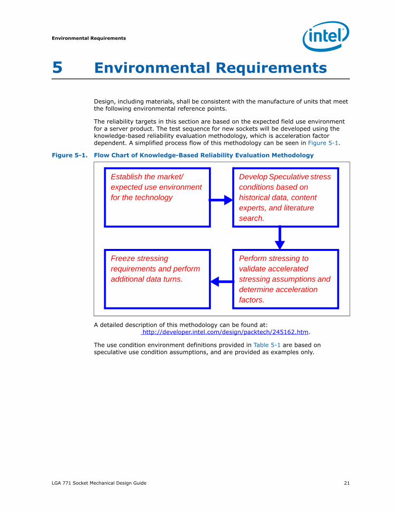
Design, including materials, shall be consistent with the manufacture of units that meet the following environmental reference points.
The reliability targets in this section are based on the expected field use environment for a server product. The test sequence for new sockets will be developed using the knowledge-based reliability evaluation methodology, which is acceleration factor dependent. A simplified process flow of this methodology can be seen in Figure 5-1.
A detailed description of this methodology can be found at: http://developer.intel.com/design/packtech/245162.htm.
The use condition environment definitions provided in Table 5-1 are based on speculative use condition assumptions, and are provided as examples only.
Figure 5-1. Flow Chart of Knowledge-Based Reliability Evaluation Methodology
Establish the market/expected use environment for the technology
Develop Speculative stress conditions based on historical data, content experts, and literature search.
Freeze stressing requirements and perform additional data turns.
Perform stressing to validate accelerated stressing assumptions and determine acceleration factors.

Environmental Requirements
22 LGA 771 Socket Mechanical Design Guide
Note: These reliability requirements are given as examples only based on speculative use condition assumptions.
Table 5-1. Use Conditions Environment
Use Environment Speculative Stress Condition
ExampleUse condition
Example7 Year stress
equivalent
Example10 Year stress
equivalent
Slow small internal gradient changes due to external ambient (temperature cycle or externally heated)Fast, large gradient on/off to max operating temp. (power cycle or internally heated including power save features)
Temperature Cycle ΔT = 35 - 44°C(solder joint)
550-930 cyclesTemp Cycle Q (-25°C to 100°C)
780-1345 cyclesTemp Cycle Q (-25°C to 100°C)
High ambient moisture during low-power state (operating voltage)
THB/HAST T = 25 –30°C85%RH (ambient)
110-220 hrs at 110 °C 85%RH
145-240 hrs at 110°C 85%RH
High Operating temperature and short duration high temperature exposures
Bake T = 95 - 105°C (contact)
700 – 2500 hrs at 125°C
800 – 3300 hrs at 125°C
Shipping and Handling
Mechanical ShockSystem-levelUnpackaged
Trapezoidal25 gvelocity change is based on packaged weight
Total of 12 drops per system:
2 drops per axis± direction
n/a
Product Weight (lbs)Non-palletized Product Velocity Change* (in/sec)
< 20 lbs 20 to > 40 40 to > 80 80 to < 100 100 to < 120 120
250225205175145125
* Change in velocity is based upon a 0.5 coefficient of restitution.
Shipping and Handling
Random VibrationSystem-levelUnpackaged
5 Hz to 500 Hz2.20 g RMS random5 Hz @ .001 g2/Hz to 20 Hz @ 0.01 g2/Hz (slope up)20 Hz to 500 Hz @ 0.01 g2/Hz (flat)Random control limit tolerance is ± 3 dB
Total per system:
10 minutes per axis3 axes
n/a

LGA 771 Socket Mechanical Design Guide 23
Environmental Requirements
5.1 Solvent ResistanceRequirement: No damage to ink markings if applicable. EIA 364-11A.
5.2 DurabilityUse per EIA-364, test procedure 09. Measure contact resistance when mated in 1st and 30th cycles. The package should be removed at the end of each de-actuation cycle and reinserted into the socket. The socket’s pick-and-place cover must be able to be inserted and removed from the socket at least 30 times.
§

Environmental Requirements
24 LGA 771 Socket Mechanical Design Guide
LGA 771 Socket Mechanical Design Guide 25
Mechanical Drawings
A Mechanical Drawings
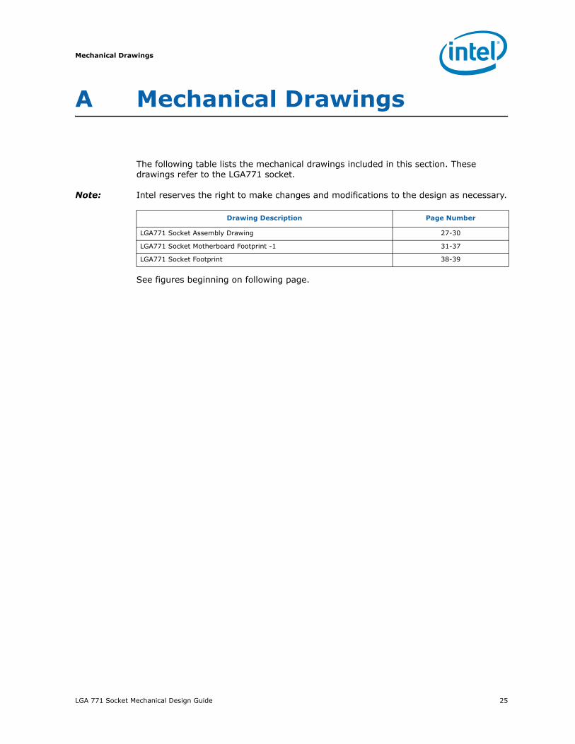
The following table lists the mechanical drawings included in this section. These drawings refer to the LGA771 socket.
Note: Intel reserves the right to make changes and modifications to the design as necessary.
See figures beginning on following page.
Drawing Description Page Number
LGA771 Socket Assembly Drawing 27-30
LGA771 Socket Motherboard Footprint -1 31-37
LGA771 Socket Footprint 38-39

Mechanical Drawings
26 LGA 771 Socket Mechanical Design Guide
Figure A-1. LGA Socket Assembly Drawing (Sheet 1 of 4)

LGA 771 Socket Mechanical Design Guide 27
Mechanical Drawings
Figure A-2. LGA Socket Assembly Drawing (Sheet 2 of 4)

Mechanical Drawings
28 LGA 771 Socket Mechanical Design Guide
Figure A-3. LGA Socket Assembly Drawing (Sheet 3 of 4)

LGA 771 Socket Mechanical Design Guide 29
Mechanical Drawings
Figure A-4. LGA Socket Assembly Drawing (Sheet 4 of 4)
Mechanical Drawings
30 LGA 771 Socket Mechanical Design Guide
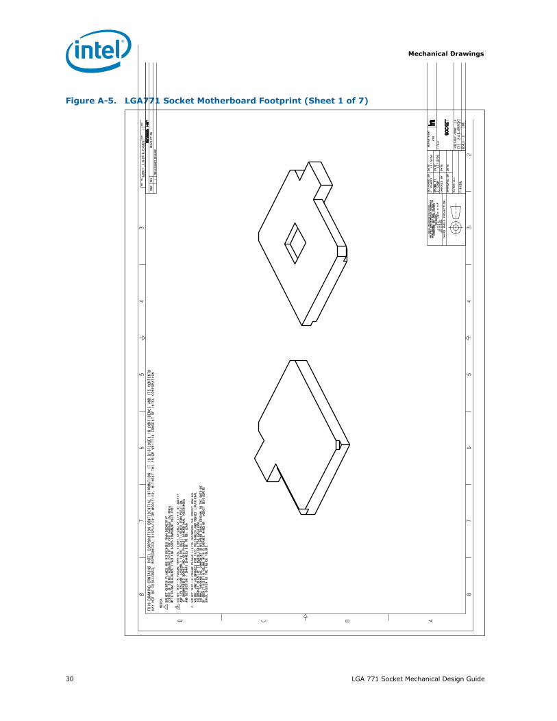
Figure A-5. LGA771 Socket Motherboard Footprint (Sheet 1 of 7)

LGA 771 Socket Mechanical Design Guide 31
Mechanical Drawings
Figure A-6. LGA771 Socket Motherboard Footprint (Sheet 2 of 7)

Mechanical Drawings
32 LGA 771 Socket Mechanical Design Guide
Figure A-7. LGA771 Socket Motherboard Footprint (Sheet 3 of 7)
LGA 771 Socket Mechanical Design Guide 33
Mechanical Drawings
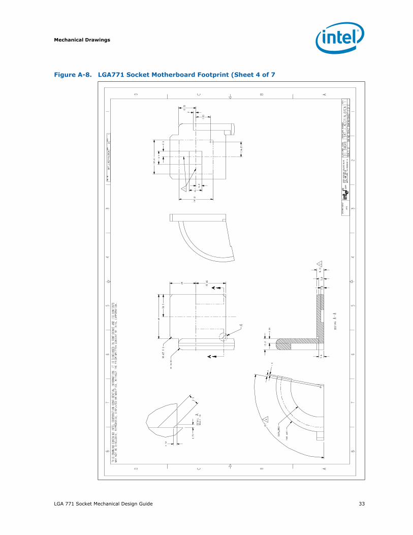
Figure A-8. LGA771 Socket Motherboard Footprint (Sheet 4 of 7
Mechanical Drawings
34 LGA 771 Socket Mechanical Design Guide
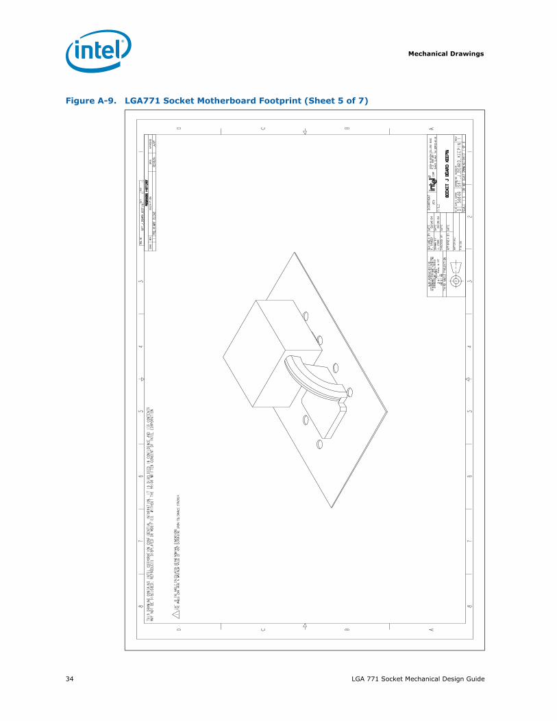
Figure A-9. LGA771 Socket Motherboard Footprint (Sheet 5 of 7)

LGA 771 Socket Mechanical Design Guide 35
Mechanical Drawings
Figure A-10. LGA771 Socket Motherboard Footprint (Sheet 6 of 7)

Mechanical Drawings
36 LGA 771 Socket Mechanical Design Guide
Figure A-11. LGA 771 Socket Motherboard Footprint (Sheet 7 of 7)

LGA 771 Socket Mechanical Design Guide 37
Mechanical Drawings
Figure A-12. LGA 771 Socket Footprint (Sheet 1 of 2)

Mechanical Drawings
38 LGA 771 Socket Mechanical Design Guide
§
Figure A-13. LGA 771 Socket Footprint (Sheet 2 of 2)