~lh1$5l - inel environmental restoration · l asce 7-98 minimum design loads for buildings and...
TRANSCRIPT

Document ID: SPC-1484 Revision ID: 0 Effective Date: 03/l l/O2
Procurement Specification
PROJECT FILE NO. 020996
Staging, Storage, Sizing and Treatment Facility
CPP 1689 Administrative Office Trailer (Aw
Prepared for: U.S. Department of Energy Idaho Operations Office Idaho Falls. Idaho
~lh1$5L Idaho National Enaineerina and Environmental LaboratorV
Form 412.14 07/24/2001 Rev. 03
Document Type: Procurement Specification Document Identifier: SPC-1484
Title: CPP 1689 Administrative Office Trailer (AOT) Project No. (if applicable): 020996
Author: D. E. Nishioka Phone: 526-5484
Document Owner: R. L. Davison Phone: 526-3770
REVIEW CONCURRENCE AND APPROVAL SIGNATURES Denote R for review concurrence, A for approval, as appropriate.
Project-Manager, E. R.
Mechanical Engineer
Electrical Engineer
l/3$= Project Engineer
Mailing Address
3930
3650
3650
3650
3650
3670
3670
3650

412.15 w21u0w
DOCUMER I MANAGEMENT CONTROL SYSTEM [DMCS) Rev, 02 DOCUMENT APPRCWAL SHEET
-__ ..~
Document Type: Praaurament Specificebn Document ldentilier; SPC-1434
Title: CPP 1689 Administrative Off& Trailer Pro+ct Nu- {if appIi&Ae): GXKI98
Author; 0. E. Nishioka Phone: 526-5484
O~JCUITWI~ Owr~et: A. L. Davi$oti Phone: 626-3770
REVIEW CQNCURRENCE AND APPROVAL $[GNATURES DwJ?@ R for rwiew coslcurre~w, A for approval, as appropriate.
Type or printed name I WA
M. Ii. Dwrnbm P.E.
Date Orgarrization Discipline
3710
.nbeperlderll Peer h.kww
J790
4pprnrar
Mailing Address
HS 3930
HS 3930
I

412.09 Cl l/05/2001 ~ Rev. 061
Specification
Procurement Document Control Center: (208) 526-1202
CPP-1689 Identifier: SPC-1484 ADMINISTRATIVEOFFICE Revision: 0
TRAILER Page: iofii Document Owner: Staff Project Manager, Project Effective Date: 0311 l/02 Management, Er
Change Number: NA
1.0 SCOPE . . . . . . . . . . . . . . . . . . . . . . . . . . . . . . . . . . . . . . . . . . . . . . . . . . . . . . . . . . . . . . . . . . . . . . . . . . . . . . . . . . . . . . . . . . . . . . . . . . . . . . . . . . . . . . . . . . . . . . . . ..... 1
1.1 GENERAL . . . . . . . . . . . . . . . . . . . . . . . . . . . . . . . . . . . . . . . . . . . . . . . . . . . . . . . . . . . . . . . . . . . . . . . . . . . . . . . . . . . . . . . . . . . . . . . . . . . . . . . . . . . . . . . . . . . . 1
1.2 WORKINCLUDED . . . . . . . . . . . . . . . . . . . . . . . . . . . . . . . . . . . . . . . . . . . . . . . . . . . . . . . . . . . . . . . . . . . . . . . . . . . . . . . . . . . . . . . . . . . . . . . . . . 1
1.3 WORKNOTINCLUDED . . . . . . . . . . . . . . . . . . . . . . . . . . . . . . . . . . . . . . . . . . . . . . . . . . . . . . . . . . . . . . . . . . . . . . . . . . . . . . . . . . . . . . . . 1
1.4 DEFINITIONS .......................................................................................................... 2
2.0 QUALIFICATIONS ........................................................................................................ 2
3.0 APPLICABLECODES,STANDARDSANDREFERENCES ..................................... 2
3.1 NATIONAL CODES . . . . . . . . . . . . . . . . . . . . . . . . . . . . . . . . . . . . . . . . . . . . . . . . . . . . . . . . . . . . . . . . . . . . . . . . . . . . . . . . . . . . . . . . . . . . . . . . . 2
3.2 INDUSTRYSTANDARDS . . . . . . . . . . . . . . . . . . . . . . . . . . . . . . . . . . . . . . . . . . . . . . . . . . . . . . . . . . . . . . . . . . . . . . . . . . . . . . . . . . . . . . . . 3
4.0 SUBMITTALS . . . . . . . . . . . . . . . . . . . . . . . . . . . . . . . . . . . . . . . . . . . . . . . . . . . . . . . . . . . . . . . . . . . . . . . . . . . . . . . . . . . . . . . . . . . . . . . . . . . . . . . . . . . . . . . . . 3
4.1 SETUPINSTRUCTIONS . . . . . . . . . . . . . . . . . . . . . . . . . . . . . . . . . . . . . . . . . . . . . . . . . . . . . . . . . . . . . . . . . . . . . . . . . . . . . . . . . . . . . . . . . . 4
4.2 PRODUCTDATA . . . . . . . . . . . . . . . . . . . . . . . . . . . . . . . . . . . . . . . . . . . . . . . . . . . . . . . . . . . . . . . . . . . . . . . . . . . . . . . . . . . . . . . . . . . . . . . . . . . . . 4
4.3 DESIGNCALCULATIONS . . . . . . . . . . . . . . . . . . . . . . . . . . . . . . . . . . . . . . . . . . . . . . . . . . . . . . . . . . . . . . . . . . . . . . . . . . . . . . . . . . . . . . 4
4.4 SPAREPARTS AND SPECIALTOOLSLIST . . . . . . . . . . . . . . . . . . . . . . . . . . . . . . . . . . . . . . . . . . . . . . . . . . . . . . . . . 4
4.5 OPERATING AND MAINTENANCEMANUALS . . . . . . . . . . . . . . . . . . . . . . . . . . . . . . . . . . . . . . . . . . . . . . . . . . . 4
4.6 DRAWINGS . . . . . . . . . . . . . . . . . . . . . . . . . . . . . . . . . . . . . . . . . . . . . . . . . . . . . . . . . . . . . . . . . . . . . . . . . . . . . . . . . . . . . . . . . . . . . . . . . . . . . . . . . . . . . . 4
5.0 DESIGN . . . . . . . . . . . . . . . . . . . . . . . . . . . . . . . . . . . . . . . . . . . . . . . . . . . . . . . . . . . . . . . . . . . . . . . . . . . . . . . . . . . . . . . . . . . . . . . . . . . . . . . . . . . . . . . . . . . . . . . . ... 5
5.1 GENERALDESIGNREQUIREMENTS . . . . . . . . . . . . . . . . . . . . . . . . . . . . . . . . . . . . . . . . . . . . . . . . . . . . . . . . . . . . . . . . . . 5
5.2 STRUCTURALREQUIREMENTS . . . . . . . . . . . . . . . . . . . . . . . . . . . . . . . . . . . . . . . . . . . . . . . . . . . . . . . . . . . . . . . . . . . . . . . . . . . 5
5.3 CONSTRUCTIONDETAILS . . . . . . . . . . . . . . . . . . . . . . . . . . . . . . . . . . . . . . . . . . . . . . . . . . . . . . . . . . . . . . . . . . . . . . . . . . . . . . . . . . . . 5

Specification
Procurement
412.09 (1 l/05/2001 ~ Rev. 06)
CPP-1689 Identifier: SPC-1484 ADMINISTRATIVE OFFICE Revision: 0
TRAILER Page: ii of ii
5.4 ELECTRICAL . . . . . . . . . . . . . . . . . . . . . . . . . . . . . . . . . . . . . . . . . . . . . . . . . . . . . . . . . . . . . . . . . . . . . . . . . . . . . . . . . . . . . . . . . . . . . . . . . . . . . . . . . . 9
5.5 HVAC . . . . . . . . . . . . . . . . . . . . . . . . . . . . . . . . . . . . . . . . . . . . . . . . . . . . . . . . . . . . . . . . . . . . . . . . . . . . . . . . . . . . . . . . . . . . . . . . . . . . . . . . . . . . . . . . . . . 11
5.6 TELEPHONE AND DATA . . . . . . . . . . . . . . . . . . . . . . . . . . . . . . . . . . . . . . . . . . . . . . . . . . . . . . . . . . . . . . . . . . . . . . . . . . . . . . . . . . . . . 12
5.7 FIRE ALARM . . . . . . . . . . . . . . . . . . . . . . . . . . . . . . . . . . . . . . . . . . . . . . . . . . . . . . . . . . . . . . . . . . . . . . . . . . . . . . . . . . . . . . . . . . . . . . . . . . . . . . . . 12
5.8 LIFE SAFETY . . . . . . . . . . . . . . . . . . . . . . . . . . . . . . . . . . . . . . . . . . . . . . . . . . . . . . . . . . . . . . . . . . . . . . . . . . . . . . . . . . . . . . . . . . . . . . . . . . . . . . . . 12
5.9 PLUMBING . . . . . . . . . . . . . . . . . . . . . . . . . . . . . . . . . . . . . . . . . . . . . . . . . . . . . . . . . . . . . . . . . . . . . . . . . . . . . . . . . . . . . . . . . . . . . . . . . . . . . . . . . . . . 13
6.0 MANUFACTURING/ASSEMBLY . . . . . . . . . . . . . . . . . . . . . . . . . . . . . . . . . . . . . . . . . . . . . . . . . . . . . . . . . . . . . . . . . . . . . . . . . . . . . . 13
6.1 GENERAL .............................................................................................................. 13
6.2 MATERIALS, PRODUCTS AND EQUIPMENT .................................................... 14
7.0 QUALITY ASSURANCE .............................................................................................. 14
7.1 SUPPLIER QUALIFICATIONS ............................................................................. 14
7.2 INSPECTIONS AND HOLD POINTS . . . . . . . . . . . . . . . . . . . . . . . . . . . . . . . . . . . . . . . . . . . . . . . . . . . . . . . . . . . . . . . . . . . . . 14
7.3 DEFICIENCIES ...................................................................................................... 14
8.0 PACKAGING AND SHIPPING ................................................................................... 15
8.1 PACKING AND PACKAGING . . . . . . . . . . . . . . . . . . . . . . . . . . . . . . . . . . . . . . . . . . . . . . . . . . . . . . . . . . . . . . . . . . . . . . . . . . . . . . . 15
8.2 MARKING AND HANDLING . . . . . . . . . . . . . . . . . . . . . . . . . . . . . . . . . . . . . . . . . . . . . . . . . . . . . . . . . . . . . . . . . . . . . . . . . . . . . . . . 15
8.3 SPECIAL TRANSPORTATION REQUIREMENTS . . . . . . . . . . . . . . . . . . . . . . . . . . . . . . . . . . . . . . . . . . . . . . . 15
8.4 DELIVERY . . . . . . . . . . . . . . . . . . . . . . . . . . . . . . . . . . . . . . . . . . . . . . . . . . . . . . . . . . . . . . . . . . . . . . . . . . . . . . . . . . . . . . . . . . . . . . . . . . . . . . . . . . . . . 16
Appendix A - Drawing List

Specification
Procurement
412.09 (1 l/05/2001 ~ Rev. 06)
CPP-1689 Identifier: SPC-1484 ADMINISTRATIVE OFFICE Revision: 0
TRAILER Page: 1 of16
1.0 SCOPE
1.1 General
This specification details the requirements for a temporary, relocatable office space for the Staging, Storage, Sizing and Treatment Facility (SSSTF), hereinafter referred to as the Administrative Office Trailer (AOT). This trailer will house a conference/lunchroom area with kitchenette, office space, data tracking technician office, toilet rooms and janitor closet. The Subcontractor will be responsible for the design and manufacture, delivery and setup of the temporary office building unit.
The portable building unit shall be transported to the Idaho Nuclear Technology and Engineering Center (INTEC) at the Idaho National Engineering and Environmental Laboratory (INEEL) approximately 50 miles west of Idaho Falls. The Contractor will install the office equipment, computer systems, perform equipment integration and complete testing before final transfer.
1.2 Work Included
The Subcontractor shall design, manufacture, deliver and set up the AOT in accordance with the applicable drawings, data sheets, and this specification. The work shall include, but is not limited to: design, construction, delivery, setup, blocking, leveling, tie-downs, install the ramps, steps, canopies, and skirting of the 28’ x 70’ portable building unit(s) and associated appurtenances. The Subcontractor shall furnish all labor, materials, equipment and services necessary to complete the work indicated on the sketches and in the specification. The Subcontractor shall procure the trailer and coordinate the construction and installation of the trailer in accordance with this specification. This specification provides the technical requirements for the AOT.
The Subcontractor shall construct the utilities and foundations for the AOT in accordance with these plans, specifications and the approved shop drawings.
1.3 Work Not Included
Installation of foundation piers shall be provided by the Subcontractor. Final connection to utilities, upon setup of AOT, will be by the Subcontractor.

Specification
Procurement
412.09 (1 l/05/2001 ~ Rev. 06)
CPP-1689 Identifier: SPC-1484 ADMINISTRATIVE OFFICE Revision: 0
TRAILER Page: 2of16
1.4 Definitions
As used herein, the following terms are defined:
l Contractor: Bechtel BWXT Idaho, LLC (BBWI) at the INEEL
l Subcontractor: The business entity under contract with Bechtel BWXT Idaho, L.L.C. (BBWI).
2.0 QUALIFICATIONS
The Subcontractor shall furnish a trailer manufactured to comply with all U.S. federal regulations applicable to manufactured housing, including the Federal Highway Administration Department of Transportation (DOT) standards and the Federal Motor Carrier Safety Regulations (FMCSR). The Subcontractor’s trailer manufacturer shall be experienced in the design and fabrication of transportable, manufactured homes and buildings.
3.0 APPLICABLE CODES, STANDARDS AND REFERENCES
The AOT shall be designed and manufactured in accordance with the codes and standards listed below. All codes and standards referenced, refer to the latest published revision on the date of the request for proposal. In the event of any inconsistency between codes, standards, and this specification, the inconsistency shall be resolved by giving precedence as follows: (a) codes, (b) standards, and (c) specification. The Subcontractor shall refer any conflicts promptly in writing to the Contractor using the Subcontractor Field Problem form.
3.1 National Codes
l AISI Cold Formed Design Specification for Structural Steel Members
l ANSI Al 17.1 Providing Accessibility and Usability for Physically Handicapped People
l ASCE 7-98 Minimum Design Loads for Buildings and Other Structures
l ASTM A572/A572M Standard Specification for High-Strength Low-Alloy Columbium-Vanadium Structural Steel
l ASTM C955 Standard Specification for Load-Bearing (Transverse and Axial) Steel Studs, Runners (Tracks), and Bracing or Bridging for Screw Application of Gypsum Panel Products and Metal Plaster Bases

412.09 (1 l/05/2001 ~ Rev. 06)
Specification CPP-1689 Identifier: SPC-1484 ADMINISTRATIVE OFFICE Revision: 0
Procurement TRAILER Page: 3of16
l ASTM C645 Standard Specification for Nonstructural Steel Framing Members
l ASTM El 52 Standard Method of Fire Tests of Door Assemblies
l ASHRAE Guide for HVAC Ducts
l AWS D1.l Structural Steel Welding
l CFR United States Code of Federal Regulations
l NFPA National Fire Protection Association
l NFPA 10 Portable Fire Extinguishers
l NFPA 70 National Electrical Code (NEC)
l NFPA 72 National Fire Alarm Code
l NFPA 80 Standard for Fire Doors and W indows
l NFPA 101 Life Safety Code
l NFPA 780 Lightning Protection Code
l OSHA Occupational Safety and Health Administration
l UE3C Uniform Building Code
l UFC Uniform Fire Code
l UPC Uniform Plumbing Code
3.2 Industry Standards
l ISDSI 102 Installation Standard for Insulated Steel Door Systems
l SD1 100 Standard Steel Doors and Frames
l SD1 108 Selection and Usage Guide for Standard Steel Doors
4.0 SUBMITTALS
The Subcontractor shall submit all data required by this specification to the Contractor for review and approval as required.

Specification
Procurement
412.09 (1 l/05/2001 ~ Rev. 06)
CPP-1689 Identifier: SPC-1484 ADMINISTRATIVE OFFICE Revision: 0
TRAILER Page: 4of16
4.1 Setup Instructions
The Subcontractor shall submit drawings and other documents, as required, to clearly identify rigging loads, pick points, and general setup instructions for the AOT.
4.2 Product Data
The Subcontractor shall submit manufacturer’s technical data for procured components that are installed in the AOT, including doors, windows, lights, HVAC, and major hardware components. The product data sheets shall identify dimensions, weights, capacities, ratings, and other interface information
4.3 Design Calculations
The Subcontractor shall submit detailed calculations for all aspects of structural design for Contractor review and approval prior to the start of fabrication. Calculations shall include welding details of AOT structural framing to embedded anchor plates to prevent uplift due to wind and/or seismic load as defined in Section 5.2.1. Calculations shall be stamped by a registered professional engineer licensed to practice Civil or Structural engineering in the State of Idaho
4.4 Spare Parts and Special Tools List
The Subcontractor shall submit a recommended list of spare parts and special tools required for maintenance and setup of the AOT.
4.5 Operating and Maintenance Manuals
The Subcontractor shall submit a data package including the Operating and Maintenance Manuals for the AOT and equipment contained within the AOT such as the central HVAC system. The Subcontractor shall include a recommended maintenance schedule for items requiring periodic servicing.
4.6 Drawings
The Subcontractor shall submit a complete set of detailed drawings for the AOT including structural, mechanical and electrical drawings. Drawings shall also include a foundation layout based on subcontract drawings. All drawings shall be reviewed and approved by the Contractor prior to fabrication. Unless otherwise specified, the drawings shall be on standard 22 X 34-inch (D-size) sheets. Submit drawings in AutoCAD 2000 format, indicating critical dimensions, weights, required clearances, components, and location/size of each field connection, including water, electrical and plumbing.
Specification
Procurement
412.09 (1 l/05/2001 ~ Rev. 06)
CPP-1689 Identifier: SPC-1484 ADMINISTRATIVE OFFICE Revision: 0
TRAILER Page: 5of16
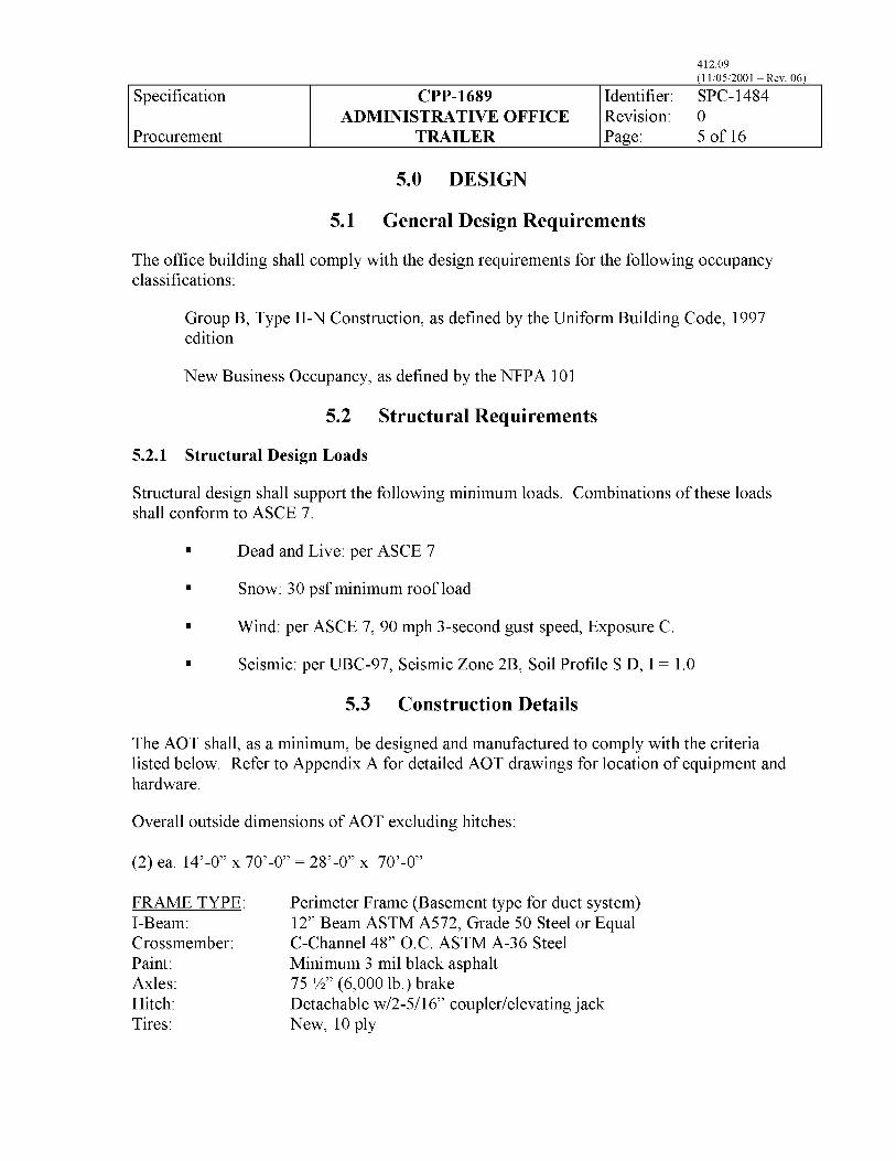
5.0 DESIGN
5.1 General Design Requirements
The office building shall comply with the design requirements for the following occupancy classifications:
Group B, Type II-N Construction, as defined by the Uniform Building Code, 1997 edition
New Business Occupancy, as defined by the NFPA 101
5.2 Structural Requirements
5.2.1 Structural Design Loads
Structural design shall support the following minimum loads. Combinations of these loads shall conform to ASCE 7.
. Dead and Live: per ASCE 7
. Snow: 30 psf minimum roof load
. Wind: per ASCE 7, 90 mph 3-second gust speed, Exposure C
. Seismic: per UBC-97, Seismic Zone 2B, Soil Profile S D, I = 1.0
5.3 Construction Details
The AOT shall, as a minimum, be designed and manufactured to comply with the criteria listed below. Refer to Appendix A for detailed AOT drawings for location of equipment and hardware.
Overall outside dimensions of AOT excluding hitches:
(2) ea. 14’-0” x 70’-0” = 28’-0” x 70’-0”
FRAME TYPE: Perimeter Frame (Basement type for duct system) I-Beam: 12” Beam ASTM A572, Grade 50 Steel or Equal Crossmember: C-Channel 48” O.C. ASTM A-36 Steel Paint: Minimum 3 mil black asphalt Axles: 75 %” (6,000 lb.) brake Hitch: Detachable w/2-5/16” coupler/elevating jack Tires: New, 10 ply

Specification
Procurement
412.09 (1 l/05/2001 ~ Rev. 06)
CPP-1689 Identifier: SPC-1484 ADMINISTRATIVE OFFICE Revision: 0
TRAILER Page: 6of16
FLOORS: Joists:
Floor Load: Bottom Board:
Insulation: Floor Decking: Underlayment: Floor Coverings:
Minimum of 2” X 8” @ 16” OC per AISI Cold Formed Design Specification for Structural steel Members 50 lbs. per square foot uniform load, 300-lb point load 18 gauge galvanized sheet metal or other suitable non-combustible material R- 19 batt insulation 314” tongue and groove sealed edge plywood Provide %” underlayment where Congoleum is applied 20-0~ commercial carpet/Class 1 (conference room and office areas), Congoleum #9092 or equivalent (NWBS STD) (data room, toilet rooms, and hallway between the data and toilet rooms, janitor storage, mechanical and electrical/communications room). Subcontractor shall provide samples to be approved by Contractor before installation
EXTERIOR WALLS: Framing: Minimum of 2”X 4” metal studs per ASTM C955 @ 16” OC Wall Height: 8’4)”
Insulation: R-19 with vapor barrier, flame-spread rating < 24 and fuel contributions/smoke development ~50.
Sheathing: N/A Exterior Siding: 24 gauge Hi-Rib Siding w 3/8” OSB Color: TBD - Subcontractor shall provide samples to be approved by Buyer Exterior Trim: 26 GA. aluminum baked enamel finish Color: TBD - Subcontractor shall provide samples to be approved by Buyer
EXTERIOR WINDOW: Qty : (7) ea. 3030 operable windows and (2) ea. 6030 by-pass
windows. Reference Floor Plan Size: 36” X 36” and 72” X 36”. Reference Floor Plan Type: Mill Finish Aluminum frame with double pane glass Blinds: Provide “mini blinds” with l-in. slats, stick operator controlling slat
tilt and pull cord raising blind opposite side, i. e., “Riviera” by Levelor
EXTERIOR DOORS: Qty : Reference Floor Plan Size: 36” X 80” steel door with Hollow Metal (H.M.) frame, 10” window
mounted in door Hardware: Lever handle with keyed locks and deadbolts, weatherstrip sealed.
All exterior doors shall be 1-hr fire rated per NFPA 80 and shall have been tested, listed, and labeled in accordance with ASTM E 152 by a
Specification
Procurement
412.09 (1 l/05/2001 ~ Rev. 06)
CPP-1689 Identifier: SPC-1484 ADMINISTRATIVE OFFICE Revision: 0
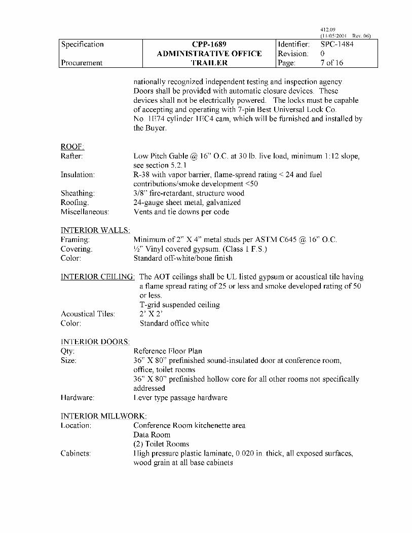
TRAILER Page: 7of16
nationally recognized independent testing and inspection agency. Doors shall be provided with automatic closure devices. These devices shall not be electrically powered. The locks must be capable of accepting and operating with 7-pin Best Universal Lock Co. No. lE74 cylinder lEC4 cam, which will be furnished and installed by the Buyer.
ROOF: Rafter:
Insulation:
Sheathing: Rooting: Miscellaneous:
Low Pitch Gable @ 16” O.C. at 30 lb. live load, minimum 1:12 slope, see section 5.2.1 R-38 with vapor barrier, flame-spread rating < 24 and fuel contributions/smoke development ~50 3/8” tire-retardant, structure wood 24-gauge sheet metal, galvanized Vents and tie downs per code
INTERIOR WALLS: Framing: Minimum of 2” X 4” metal studs per ASTM C645 @ 16” 0.C Covering: l/2)’ Vinyl covered gypsum. (Class 1 F.S.) Color: Standard off-white/bone finish
INTERIOR CEILING: The AOT ceilings shall be UL listed gypsum or acoustical tile having a flame spread rating of 25 or less and smoke developed rating of 50 or less. T-grid suspended ceiling
Acoustical Tiles: 2’ x 2’ Color: Standard office white
INTERIOR DOORS: Qty : Reference Floor Plan Size: 36” X 80” pretinished sound-insulated door at conference room,
office, toilet rooms
Hardware:
36” X 80” pretinished hollow core for all other rooms not specifically addressed Lever type passage hardware
INTERIOR MILLWORK: Location: Conference Room kitchenette area
Data Room (2) Toilet Rooms
Cabinets: High pressure plastic laminate, 0.020 in. thick, all exposed surfaces, wood grain at all base cabinets

Specification
Procurement
412.09 (1 l/05/2001 ~ Rev. 06)
CPP-1689 Identifier: SPC-1484 ADMINISTRATIVE OFFICE Revision: 0
TRAILER Page: 8of16
Countertops:
Hardware:
High-pressure plastic laminate, l/16” thick. Countertops w/particleboard core Standard cabinet hinges, drawer slides, pulls and locks
INTERIOR TRIM Base: 4” vinyl cove base Miscellaneous: Standard wood-grain profiles Vinyl wrapped battens
STEPS: Qty :
CANOPIES:
TIE DOWNS:
SKIRTING: Framing: Height: Insulation:
Sheathing: Exterior Siding:
LETTERS:
Material: Letter Style: Letter Size: Finish:
Provide 2 sets of steps with landings, ramp and railing as shown on floor plan layout. Fabrication design shall conform with the latest edition of UBC and NFPA 101, Life Safety Code and ANSI Al 17.1 for the ramp.
Non-slip surface Welded steel and aluminum construction Meet OSHA safety parameters including handrails
Provide protection over exterior access landings as shown on drawings. Conform to structural requirements of Section 5.2. Canopy design shall include the impact of falling snow and ice, per the Uniform Building Code.
Anchor plates embedded in piers to secure AOT from wind loads defined in 5.2.1
Matching skirting around base of AOT Minimum of 2”X 4” metal studs per ASTM C645@ 16” O.C. Approximately 3’-0” a.f.g. R-19 with vapor barrier, flame-spread rating < 24 and fuel contributions/smoke development ~50. 3/4” all weather, tire-retardant plywood 24 gauge Hi-Rib Siding w 3/8” SOB
Provide and install on site, building identification letters as shown on Drawings. l/2 inch plate aluminum Microgamma Bold 24-in. high, % in. deep Baked enamel finish with 5-year guarantee against cracking, peeling and discoloration

Specification
Procurement
412.09 (1 l/05/2001 ~ Rev. 06)
CPP-1689 Identifier: SPC-1484 ADMINISTRATIVE OFFICE Revision: 0
TRAILER Page: 9of16
Color: Black
Install per manufacturer’s instructions using a concealed fastener method Letters shall project l/2 in. from wall surface.
5.4 Electrical
The electrical systems in the AOT shall be in accordance with the following provisions:
Incoming Service: A 48OY/277 Volt, 3 Phase, 4 Wire, 60 Hz electrical service is available in the vicinity of the AOT location. The total demand for the administrative trailer shall not exceed 50 amperes per phase. The Trailer shall be supplied with a service junction box on the outside for a single point connection of the incoming service. The junction box shall be located on the east end of the building on the outside wall of the electrical room.
Interior Lighting:
Exterior Lighting:
General interior lighting shall be provided by 2’ X 4” recessed fluorescent fixtures. The fixtures shall be equipped with high efficiency electronic ballasts and 32 watt high efficiency, low mercury, fluorescent lamps. The lamps shall be designed to pass the Environmental Protection Agency’s Toxicity Characterization Leaching Procedure (TCLP) requirements at end of life. Fixtures located in the cubicles and the office area shall be equipped with low glare diffusers suitable for use in areas where video display terminals are in use. At least one light in each hallway shall be unswitched and remain energized at all times. Lighting in the cubicle area shall be switched. The switches shall be close to the entrances to the cubicle area. Lighting in the conference room shall be switched to provide a minimum of three levels of illumination. Fixtures around the perimeter of the conference room shall be separately switched to facilitate slide/video presentations. Lighting in other rooms shall be controlled by one switch located at the entrance to the room. Illumination levels shall be as recommended by the Illuminating Engineering Society Handbook.
Exterior lighting fixtures shall be located at each entrance. The fixtures shall be rated for exterior use, shall contain a 75-Watt High Pressure Sodium Lamp and shall be Dark Sky compliant. Each fixture shall be controlled by a Photoelectric Cell that is an integral part of the fixture.

Specification
Procurement
412.09 (1 l/05/2001 ~ Rev. 06)
CPP-1689 Identifier: SPC-1484 ADMINISTRATIVE OFFICE Revision: 0
TRAILER Page: lOof
Emergency/Exit Lights: Emergency Lighting and Exit Lighting shall be provided in accordance with Sections 7.9 and 7.10 of NFPA 101, Life Safety Code, 2000 Edition. Emergency and Exit Lighting fixtures shall be self contained battery powered units.
Standard Receptacles: Receptacles shall be provided in accordance with standard industry practice for offices. Each office space shall be on an individual circuit. The receptacle on the east wall of the electrical/communications room shall be on an individual, dedicated circuit.
All standard single and duplex receptacles shall be specification grade, 20 Ampere, 125 Volts in a NEMA 5-20R configuration
GFCI Receptacles
Labeling:
Wiring:
Code Compliance:
Ground Fault Circuit Interrupter (GFCI) type receptacles shall be installed in all locations required by the National Electrical Code. A GFCI circuit breaker shall be installed in the circuit breaker panel on the circuit feeding the required receptacles or individual GFCI type receptacles shall be installed at each location. Feed through wiring that allows the GFCI receptacle to provide GFCI protection for receptacles located downstream shall not be allowed. Where GFCI protection is provided by a circuit breaker, each receptacle shall be clearly labeled as being GFCI protected.
All switches and receptacles shall be labeled to identify the source of power including the panel designation, circuit number and voltage if other than 120 volts. Labels shall be firmly attached to the covers. Labels shall be engraved material such as lamicoid or equivalent.
Common neutrals i.e. Edison type circuits shall not be allowed. Where a neutral conductor is required, a dedicated neutral conductor shall be provided for each phase conductor.
The complete installation shall be in accordance with applicable sections of the National Electrical Code including Article 550 - Mobile Homes, Manufactured Homes, and Mobile Home Parks.

Specification
Procurement
412.09 (1 l/05/2001 ~ Rev. 06)
CPP-1689 Identifier: SPC-1484 ADMINISTRATIVE OFFICE Revision: 0
TRAILER Page: llof16
Spare Conduits:
Grounding:
Lightning Protection: A Lightning risk Assessment shall be performed in accordance with NFPA 780. If the risk value is determined to be “Moderate to Severe” or “Severe”, lightning protection in accordance with NFPA 780 shall be provided. Ground rods and final connection to the ground rods shall be the responsibility of the Buyer and approved by the Contractor. Down conductors with a minimum of 10 feet of slack will be provided by the trailer manufacturer.
Two 3/4 in. spare conduits shall be provided from the 120 volt panel to a 6”x6”~4” NEMA-3R box located on the outside wall of the electrical room. This box shall be adjacent to the incoming service junction box.
The grounding electrode system will be provided by the Buyer. The Buyer will provide the connection to the grounding electrode system from a point identified by the Supplier.
5.5 HVAC
The HVAC system shall comply with the requirements listed below:
The supply air system will be operating at a site near INTEC, approximately 50 miles west of Idaho Falls. The 97-l/2% ASHRAE data for this area shall be used for mechanical design purposes.
The HVAC system shall maintain the following conditions inside the AOT:
Summer temperature: 76°F
Winter temperature: 72°F
The Subcontractor shall take into account standard heating and cooling loads. In addition, one personal computer and laser jet printer per office shall be accounted for as well as a central copy machine.
The system shall be designed to allow individual control of the temperatures in the Conference/Lunchroom and each side of the facility shall be on separate zone controls.
All ductwork shall conform to Sheet Metal and Air Conditioning Contractor’s National Association (SMACNA) specifications and designs to minimize noise and pressure drop.

Specification
Procurement
412.09 (1 l/05/2001 ~ Rev. 06)
CPP-1689 Identifier: SPC-1484 ADMINISTRATIVE OFFICE Revision: 0
TRAILER Page: 12 of 16
Outlets:
Equipment:
Testing:
Installation of the system shall conform to the manufacturer’s recommendations, ASHRAE Standards and NFPA 90A and 90B.
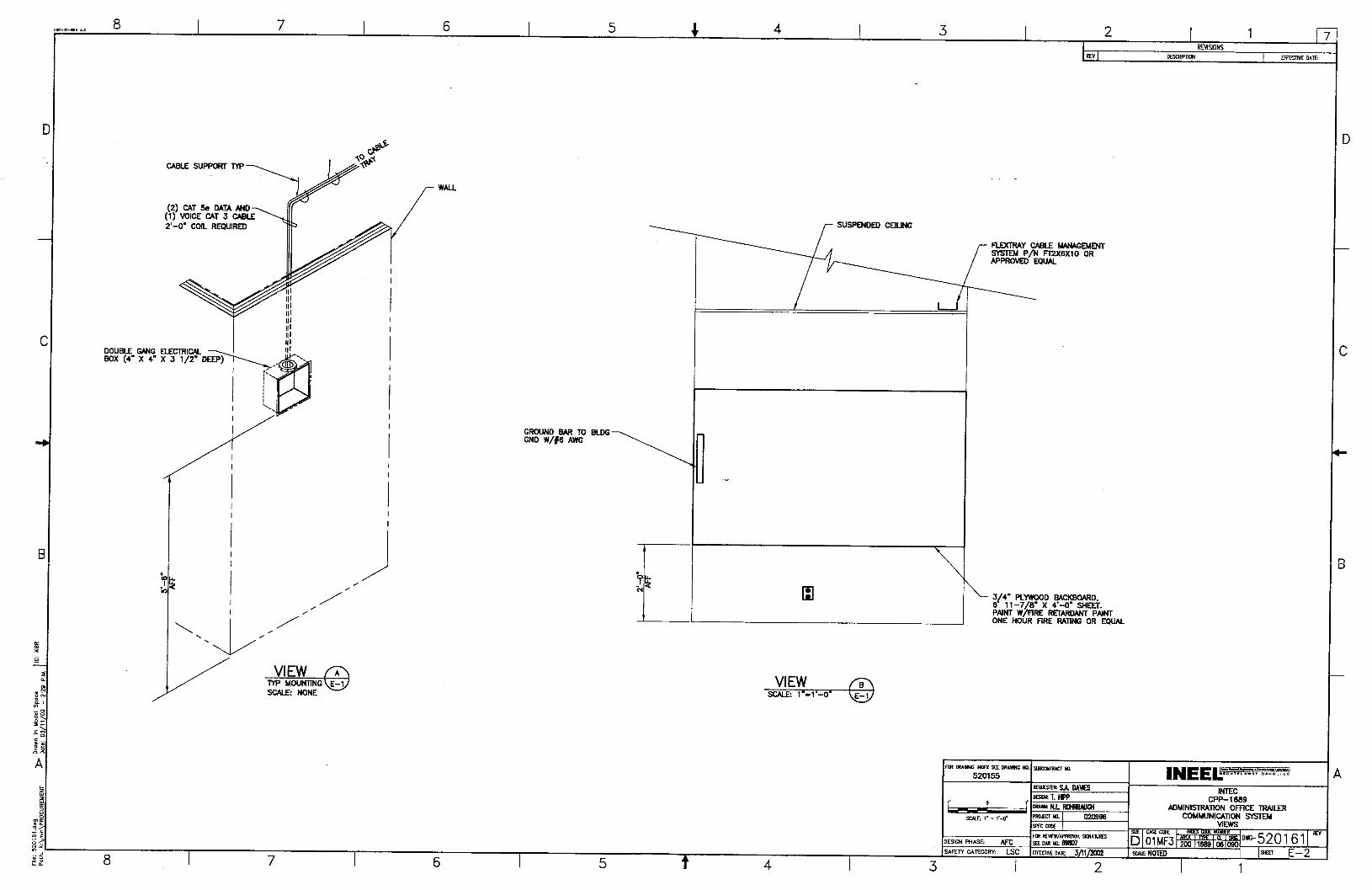
5.6 Telephone and Data
The Subcontractor shall install voice/data/data outlet boxes at locations indicated on drawings E-l. The Subcontractor shall install all components indicated on drawing E-2. The voice cable shall be white while the data cable shall be blue.
The Subcontractor shall install all equipment in the communication room as indicated on drawing E-2.
All equipment shall comply with NEC Article 800 for telephone systems and service. All components shall be UL approved.
The Subcontractor shall inspect cables for physical damage and confirm continuity.
5.7 Fire Alarm
The Subcontractor shall provide the wiring, conduit, electrical back-boxes, electrical connections, etc to make a complete and operational system. The Subcontractor is responsible for supplying all of the fire alarm equipment including a Digital Alarm Communications Transmitter (DACT). The Subcontractor shall install the fire alarm system wiring, back boxes and equipment shown on the fire alarm drawing in Appendix A. The system shall be installed in accordance with NFPA 72. The wiring for initiation device circuits shall be Class B, Style B. The occupant notification device circuits shall be Class B, Style Y.
Provide and install one # 18 gauge supervised pair of conductors between the manual fire alarm stations located as shown and the fire alarm control panel. The manual fire alarm stations shall be mounted on a single gang-type outlet box.
Provide and install one # 14 gauge supervised pair of conductors between the audible/visual devices and the fire alarm control panel. The audible/visual devices shall be mounted on a 4 square back-box either located in the wall or in the suspended ceiling.
Install a % inch conduit with three pair of telephone conductors and one # 18 pair from the fire alarm control panel to the telephone backboard. The DACT will be connected and programmed by others.
5.8 Life Safety

Specification
Procurement
412.09 (1 l/05/2001 ~ Rev. 06)
CPP-1689 Identifier: SPC-1484 ADMINISTRATIVE OFFICE Revision: 0
TRAILER Page: 13 of 16
The AOT shall comply with federal fire protection related life safety and emergency planning requirements contained in 29 CFR 1910, Occupational Safety and Health Standards NFPA 101 shall apply where 29 CFR 1910 does not apply or where NFPA 101 exceeds the requirements in the CFR. The life safety designs shall include provision for safe access and rapid movement of emergency equipment in accordance with applicable standards. Life safety provisions (access, emergency egress, emergency lighting, and smoke alarms) shall be provided in accordance with Life Safety Code NFPA 101 as a minimum.
5.9 Plumbing
Plumbing includes water supply and sewage piping for potable water, drains, waste piping and vent piping. Also included are plumbing fixtures, pipe supports and other accessories as needed to provide a complete plumbing system. All piping shall be installed within the AOT insulation envelope to prevent freezing. The potable water line shall be provided with an easily accessible main shut-off valve along with a heat tape system or equivalent to keep the line from freezing. Plumbing systems shall comply with the Uniform Plumbing Code and shall be selected based on the best combination of performance, cost and maintenance.
PLUMBING
Supply Lines Wastelines Water Heater Toilet Lavatory Sink Mop Sink Accessories
Copper manifold to through-floor inlet PVC-DWV-SCH 40 waste and vent lines 6-gallon electric/switched Qty: (2) ea., 1.6 gal flush china bowl and tank Cabinet with sink and faucet, one each toilet room Cabinet, counter top w/sink in Conference Room Locate a floor mop sink in Janitor Storage Room Per each toilet room Toilet paper holder Wall Hung mirror Paper towel and soap dispenser Handicap grab bars Coat hooks Toilet seat cover dispenser Waste receptacle Sanitary napkin dispenser in Women’s Toilet Room Sanitary napkin disposal in Women’s Toilet Room
6.0 MANUFACTURING/ASSEMBLY
6.1 General

Specification
Procurement
412.09 (1 l/05/2001 ~ Rev. 06)
CPP-1689 Identifier: SPC-1484 ADMINISTRATIVE OFFICE Revision: 0
TRAILER Page: 14 of 16
The AOT shall be fabricated using commercial assembly techniques, materials, and procedures typically used at the manufacturing plant performing the construction and assembly.
6.2 Materials, Products and Equipment
Materials, products and equipment shall be new and installed in accordance with manufacturer’s current published recommendations, the contract drawings, and these specifications. Items used in quantity, such as valves and hardware shall in each case be the product of one Supplier and shall be used only for the services recommended by the manufacturer.
7.0 QUALITY ASSURANCE
7.1 Supplier Qualifications
The AOT shall be designed and fabricated by a trailer manufacturer that is qualified and regularly engaged in the design and fabrication of mobile office trailer and classrooms. Provide proof of experience, minimum five years, as a manufacturer with a successful record of in-service performance in the fabrication and setup of these structures and with the quality indicated. The trailer manufacturer shall maintain a shop and facilities for fabrication of such structures.
7.2 Inspections and Hold Points
Witness and hold points are specific points in the activity requiring witnessing and/or surveillance by the Subcontractor and Contractor. Activities shall not proceed past a hold point without witness and/or surveillance by the Subcontractor and Contractor unless specifically waived in writing by the Contractor. (Witness and hold points, if necessary, will be identified to the Subcontractor during the initial phase of work.)
7.3 Deficiencies
The Subcontractor shall resolve all deficiencies, i.e. non-conformances as noted, to the Contractor’s satisfaction. The Contractor’s concurrence with “use-as-is” or “repair” disposition of any nonconformance must be obtained. Such concurrence will not be unreasonably withheld. The terms “use-as-is,” “repair,” and “rework’ are defined as:
l “Use-as-is” is a disposition permitted for a nonconforming item when it can be established that the item is satisfactory for its intended use.
l “Repair” is the process of restoring a nonconforming characteristic to a condition such that the capability of an item to function reliably and safely is unimpaired, even though that item still does not conform to the original requirements.

Specification
Procurement
412.09 (1 l/05/2001 ~ Rev. 06)
CPP-1689 Identifier: SPC-1484 ADMINISTRATIVE OFFICE Revision: 0
TRAILER Page: 15of16
l “Rework’ is the process by which an item is made to conform to original requirements by completion or correction.
8.0 PACKAGING AND SHIPPING
8.1 Packing and Packaging
Prior to shipping, the Subcontractor shall protect openings in casings, housings and enclosures with plywood. The Subcontractor shall protect pipe flanges with plywood secured with a minimum of four bolts and protect pipe threads with plastic end caps or plugs. The seal closure caps and plugs shall provide a water and dust tight seal. Temporarily seal all open conduit connections, open wiring, and conductors.
8.2 Marking and Handling
With the equipment shipping documents, the Subcontractor shall provide complete identification and location of temporary material contained within the equipment for shipment, handling or storage, which must be removed prior to commissioning, including shipping blocks, desiccant bags, components shipped inside larger sections, and provide instructions for removal, as required. An identification tag shall be mounted on the external surface of the trailer indicating date of manufacture, manufacturer’s address, and purchase order number.
The Subcontractor shall provide written recommendations for field storage, transportation and handling of the AOT.
8.3 Special Transportation Requirements
The Subcontractor shall make arrangements and obtain permits for transporting the AOT from the trailer maufacturer’s fabrication facility to the INEEL Site approximately 50 miles west of Idaho Falls, ID. The Subcontractor shall be responsible for protecting and transporting the AOT to the Contractor’s facility at the INEEL.
The Subcontractor shall be responsible for dimensional stability and overall integrity of the equipment during shipment. Any special lifting, rigging, or setting procedures shall be provided with the equipment. The center of gravity shall be clearly marked on the equipment for hoisting and rigging purposes.
The Contractor shall retain the transportation axles, wheels, and tires.

Specification
Procurement
412.09 (1 l/05/2001 ~ Rev. 06)
CPP-1689 Identifier: SPC-1484 ADMINISTRATIVE OFFICE Revision: 0
TRAILER Page: 16of16
8.4 Delivery
Prior to shipment, at the discretion of the Contractor, the Contractor may inspect the AOT for conformance to this purchase specification. The inspection will take place at the trailer manufacturer’s facility. The Subcontractor shall not ship the trailer to the INEEL until receiving written authorization from the Contractor.

Specification
Procurement
412.09 (1 l/05/2001 ~ Rev. 06)
CPP-1689 Identifier: SPC-1484 ADMINISTRATIVE OFFICE Revision: 0
TRAILER Page: 1 of9
DRAWING NUME3ER
C-l
U-l
A-l
A-2
S-l
E-l
E-2
LSS-1
Appendix A
DRAWING LIST
TITLE
Site Plan and Drawing List
Utilities Plan (For Information Only)
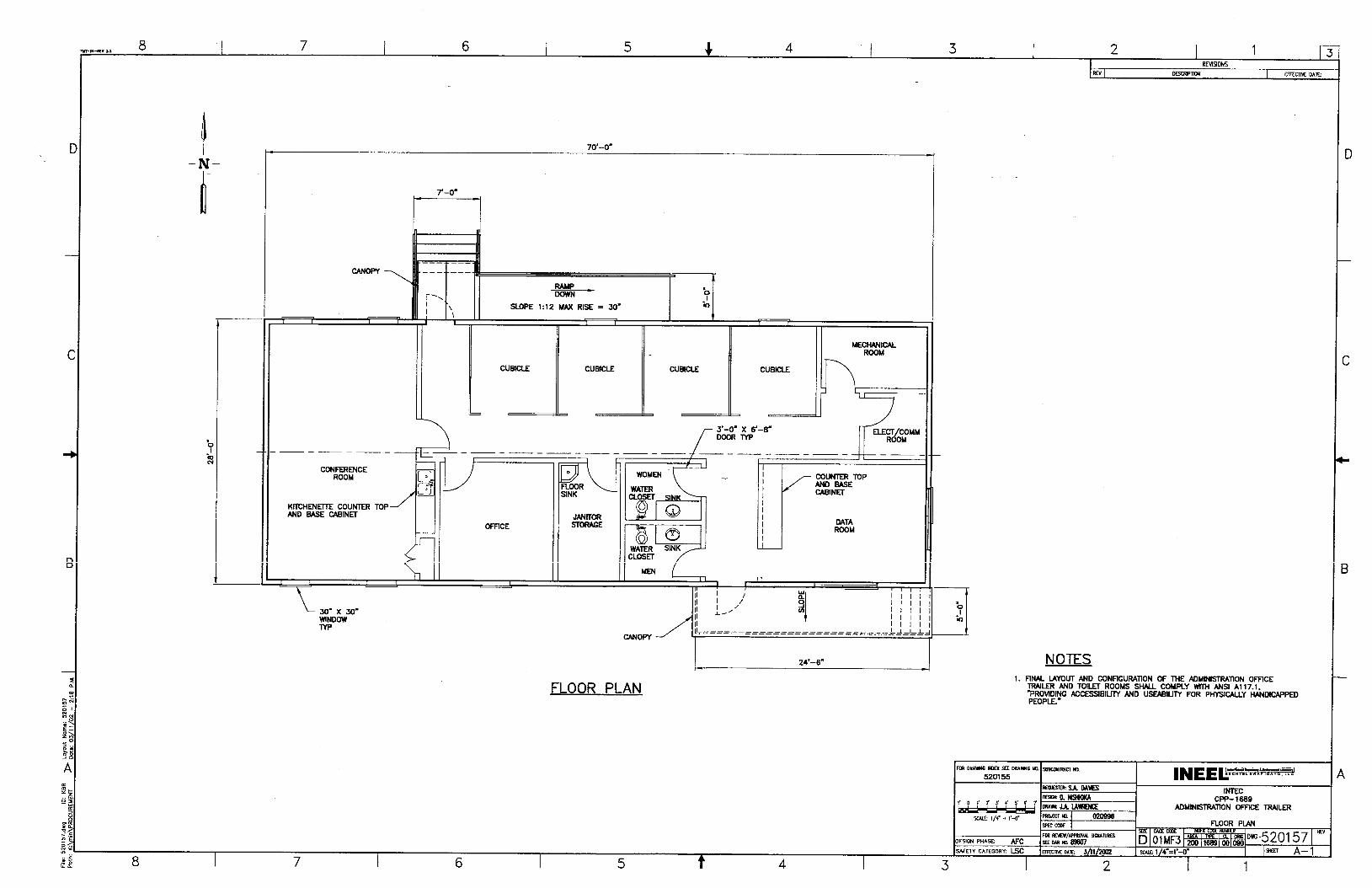
Floor Plan
Elevations
Foundation Plan
Voice/Data Data Outlet Floor Plan
Views
Life Safety Systems Plan and Fire Alarm Riser Diagram

8 I 7 6 5 4 4 I 3 2 1 fi -o,-IEV 3.3 ^_.. -_ _
SSSTF SITE PLAN SCKE: l’-a.0
DRAWING LIST 1 C-l
2 u-l
3 A-l
4 A-2
5 El
6 E-l
7 E-2
a ts-1
520155
520156 520157
520153
520159
526160
520161
520162
CPP-1669 ADMINISTRATION OFlXE TRAILER
7 6 5 t 4

L- t
T
-
c-.
-
w
-
tf
1
if
-
cc
--
b
-
K
----_ -----;: ------II -----II ---.--_ B
/;
~
11 1; II 11 0 1; 11 II
--x---x--x--x-
1 I ----T-+=
t m
r-m-RN w 8 7 6 5 4 4 3 2 1 l-
RMSlONS
RN -TIoW 1 LTEcobt DATE:
F
r-. I . I \
i \ I
FE%- SLOPE 1:12 MAX RISE = SO’
I I
FLOOR PLAN
------_ I I
COUNTER TOP AND BASE CABINET
i I DATA ROOM
--- ---
CONFERENCE ROOM
KlTCHENETlE COUNTER TOP AND BASE CABINET
HEN
30’ x 30’ s In I I I I
WINDOW 1; A-’
I lYP I I I I
CANOPY ~======--------==-----=====~~-I-~-
24’-6’ NOTES 1. FINAL IAYDUT AND CONflGURATlON OF THE ADMINISTRATION OmCE
TRAILER AND TOlLI ROOMS SHALL COMPLY WITH ANSI Al 17.1, =F’RoF’R~!4G ACCESSIBILITY AND USEMUM FOR PHYSKXLLY HANDICAPPED
7 6 5 4
CPP-1669 ADMINISTRATION OFFICE TRAILER

,
.o-,o I

cm-I” 3.2 8 7 6 5 4 4 3 I 2 I 1 e
,- TUBE FORM
ANCHOR PLAlE CENTER IN PIER
6’-0 S/S= 6’4 5/s= 6’-8 5/8’ 8’4 5/E’ 6’-8 5/B’ 8’4 5/8’ 6’4 5/0’ 0’4 5/8’ 6’-8 518’ 6*-E S/8-
OUTLINE OF TRAILER BY OTHERS
d --- d -d ----___ d- 0
d 1 -----__ /- N 693.282.52 E 295.556.46 --
ANCHOR PLATE AND ANCHORAGE INTO PIER AS DESlGNED BY MDDUIAR TRAILER MFR
TRAILER FLDCR
n C- FOUNDATION 36 PIACES
“-@
0 0 0 rG.c__<. _ -._ EL 4925.00
TOP DF PIER
#4 CIRCULAR RRNFORCING W/ l’-0” OVERLAP AT 12’ OC
UNDISTURBED SOIL
0
---
9’-7 l/8’ 9’-7 l/8’ 9’-7 i/a’
E
L N 693.254.52 E 295.466.47
FOUNDATION PLAN NOTE SCALE: 1/4==1’-0’
THIS SHEET IS “INFORMATION ONLY” FOR THE BUILDING SUPPLIER. THE ELEVATION
FOUNDATION IS TO BE COORDINATED WITH THE SUPPLIER AND CONSTRUCTED BY THE SUBCONTRACTOR - SEE THE CONTRACT PLANS.
CPP- 1689 ADMINISTRATION OmCE TRAJLER

NFot-RN u 8 7 6 5 4 3 2 1 WAMSIONS
REV ( xx.wnm / Emcnkt DATE:
LEGEND
44 VOICE/DATA/DATA OUtLET
.g~~ll~t+ CABLE TRAY ABOVE SUSPENDED CEILING
A6-0
TERMINAL NUMBER PATCH PANEL NUMBER
t f
820 2-v A2-D
11-D 82-D
18-V Al B-D 018-D
17-v 1 A17-D
817-D
A3-D B3-D
/- COMMUNKMlON BACKBOARD
LAST OUTLET NO. USED
VOICE OUTLET NO. 18-V
DATA/DATA OUTLET NO. Al&D 8 Bl&D I
* 8-V A6-D B&-D
16-V I Al&D
816-D
14-v Al 4-D El 4-D
I -.> 9-v A9-D 89-D
13-v Al 3-D 013-D 815-D
VOICE/DATA FLOOR PLAN
‘-D1-Rw 13
8
7 6 5 4 4 3 2 1 r RMSONS
REV] DEscwpnoN 1 EFEcmE DIE
/
WALL
- y-O= COIL REQUIRED SUSPENDED CEILING
FLDmAY CANE MANAGEMENT S Y S T E M P/N Fl2XGXlO OR APPROVED EQUAL
GROUND EAR TO BLDG GND W/#6 AWG
\ 314’ PLYWOOD BACKBOARD, 6 11-7/S= X 4’-0’ SHEET. PAINT W/FIRE REVRDANT PAINT ONE HOUR flRE RATING OR EQUAL
5
CPP- 1669 ADMINISlRAl lON OFFICE TRMER
COMMUNlCAl lON S Y S T E M
D I- E-2

MANUAL FiRE AlAW STATIONS - . %
l-2 l-l
Eoj- -CT:- _ - _-$J _ _ - FTI- _ - - 2-4 2-3 2-2
c Y BY OTHERS
12oVAC +
1 (FlRE ALARMFC%OL PANEl
4 IDC (CUa B. S’MX B) 2 N4C (CLASS 8. STYLE W)
24 HR BATTERY SUPPLY + 5 MINUTE ALARM
I 1 SW
15 CD 30 CD 30 CD 15 CD
FIRE ALARM RISER DIAGRAM SCAUZ NONE
llui I \ \ l-l 1
MECHANICAL ROOM
CUNICLE CUBICLE CUBICLE CUBICLE
l/2% W/3 PAlR TELEPHONE CABLE & 2#18
.,-,.. C ..CI.-., ROOM
JANITOR OrnCE STORAGE
DATA ROOM
ii / ,I’ I I I I I II II L-
, 1 I I I I I I I I I I I I I I
~===-==================~===~~=,=~~
COYMUNlCATlONS BACKBQARD
LEGEND
El IYI III El cla
XX CD
ITi X IFACPJ
EEI
aiD
a
MANUAL flRE ALARM STAnON
SPRINKLER WATER !XOW
SPWNKLER VALVE SUPERVISORY TAMPER SWITCH
LOW AIR PRESSURE SUPERVlSORY SWITCH
AUDIBLE OCCUPANT NOnflCAnON DMCE
CANDELLA RAnNG (MINIMUM)
AUDIBLE/VISUAL OCCUPANT NOTlf lCATlON DMCE
FIRE AIARM CONTROL PANEL
DlGliAL ALARM COMMUNICATION TRANSMrrraZ
END-OF-LINE DMCE
TELEPHONE LINE PLUG
4. CONDUtT SHALL BE OTHERWISE NOTED.
EMT UNLESS
NOTES 1. CEILING MOUNTED AUDIBLE/WSIEIJI DMCE.
2. AUDIBLE/VISIBLE DEVlCE 96. ABOVE flNlSHE0 FLOOR.
3. INSTALLATION HElGHT 40’ ABOVE FlNlSHED FLOOR TO CENTER OF DEVICE.
LSS PLAN SCALE2 l/4’- 1 ‘-0’ CPP- 1689
ADMlNlSTRATlON OFFICE TRAJLER LIFE SMETY SYSTEMS
lssPuN&FllEuJwmsERIlww