library punching technology
DESCRIPTION
Library Punching TechnologyTRANSCRIPT

Technical Information
PunchingTechnology, tools, practical operation


Technical information
Punching Technology, tools, practical operation
Edition: 10/2006

Ordering information Please state the title of the document, the language required, and the date of issue. TRUMPF Werkzeugmaschinen GmbH + Co. KG Technische Dokumentation Johann Maus Straße 2 D-71254 Ditzingen Phone: +49 (0) 71 56/3 03-0 Fax: +49 (0) 71 56/3 03-5 40 Internet: http//www.trumpf.com E-mail: [email protected]
This document has been compiled in the Technical Documentation department at TRUMPF Werkzeugmaschinen GmbH + Co. KG. All rights to this documentation, especially the rights of reproduction and distribution as well as that of translation are retained by TRUMPF Werkzeugmaschinen GmbH + Co. KG. This also applies in cases of notifications of protected privilege. Without previous written consent of TRUMPF Werkzeugmaschinen GmbH + Co. KG, no part of the documentation, no matter in which form, may be reproduced or processed, copied or distributed using electronic systems. Subject to errors and technical modifications. © TRUMPF Werkzeugmaschinen GmbH + Co. KG TRUMPF Werkzeugmaschinen GmbH + Co. KG is not liable for any errors in this documentation. Liability for direct and indirect damage or injury resulting from the delivery or use of this documentation is excluded, in so far as this is legally permissible.

T450EN.DOC Before you read on... 5
Before you read on...
The technical information provided in "punching" gives you access to essential themes concerning punching, nibbling, and forming. The components of a punching machine are described after a short description of necessary terminology. An introduction to TRUMPF tool systems then follows. Main themes are also covered such as quiet punching, scratch-free machining, and measures for retaining flat sheets. Information and tips from practical operation round the themes off. At the end of the section on technical information on "punching", you will find an appendix and an index which will give you quick reference in finding the information you require. More profound information on special themes or single tools appear in further technical information and tool information manuals.
On the contents

6 Table of contents T450EN.DOC
Table of contents 1. Punching, nibbling, forming............................................3 1.1 Definitions and terminology ................................................3
Punching .......................................................................3 Nibbling .........................................................................3 Forming .........................................................................3
2. Punching machine concept.............................................3 2.1 Components of a punching machine ..................................3
C-frame .........................................................................3 Hydraulic punching head ...............................................3 Tool adapter ..................................................................3 Linear magazine............................................................3 Coordinate guide ...........................................................3 Machine tables ..............................................................3 CNC control...................................................................3
2.2 Punching ............................................................................3 Machine loading ............................................................3 Program execution ........................................................3 Part removal ..................................................................3 Clamp dead areas .........................................................3 Repositioning.................................................................3 Automatic acceleration programming ............................3
2.3 Tool management ..............................................................3 2.4 Automation .........................................................................3
3. Toolsystem .......................................................................3 3.1 Punch with alignment ring ..................................................3 3.2 Stripper...............................................................................3 3.3 Die......................................................................................3 3.4 Criteria for toolselection......................................................3
Tools and workpiece .....................................................3 Tools and machining quality ..........................................3 Tools and company requirements .................................3
3.5 Tooltypes............................................................................3 3.6 Toolcare .............................................................................3
Sharpening tools ...........................................................3 Setting tools with QuickSet............................................3 Setting tools with setting fixture .....................................3 Loading tools with QuickLoad........................................3 Sticking tools with adhesive pads ..................................3 Storing tools ..................................................................3
3.7 Toolcatalog.........................................................................3
4. Quiet punching and nibbling with Softpunch ................3

T450EN.DOC Table of contents 7
4.1 Introduction ........................................................................3 4.2 Comparison: punching and nibbling with and
without Softpunch...............................................................3 4.3 Sequence of a hit rate ........................................................3 4.4 Parameters for noise reduction...........................................3 4.5 Table collection ..................................................................3
5. Punching and nibbling without scratches......................3 5.1 Brush tables .......................................................................3 5.2 Special tools .......................................................................3
Adhesive pads...............................................................3 Slug retaining dies.........................................................3 Additional measures......................................................3
5.3 The answer: combine different measures...........................3 5.4 Tips for practical operation .................................................3 5.5 Other options......................................................................3
6. Flatness of sheets during punching and nibbling .............................................................................3
6.1 Introduction ........................................................................3 6.2 Causes of deformation .......................................................3 6.3 Strategies for reducing deformation....................................3
Selection of suitable punches and dies..........................3 Strain-free machining through correct tool choice............................................................................3 Use of the presser foot ..................................................3 Pre- and post-punching .................................................3
7. Appendix...........................................................................3 7.1 Operation of the hydraulic punching head ..........................3 7.2 Tables of maximum capacities ...........................................3 7.3 Feed step ...........................................................................3 7.4 Tensile strength..................................................................3
8. Index................................................................................93
8 Punching, nibbling, forming T450EN.DOC
1. Punching, nibbling, forming
1.1 Definitions and terminology
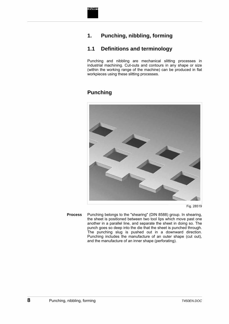
Punching and nibbling are mechanical slitting processes in industrial machining. Cut-outs and contours in any shape or size (within the working range of the machine) can be produced in flat workpieces using these slitting processes. Punching
Punching belongs to the "shearing" (DIN 8588) group. In shearing, the sheet is positioned between two tool lips which move past one another in a parallel line, and separate the sheet in doing so. The punch goes so deep into the die that the sheet is punched through. The punching slug is pushed out in a downward direction. Punching includes the manufacture of an outer shape (cut out), and the manufacture of an inner shape (perforating).
Fig. 28519
Process

T450EN.DOC Punching, nibbling, forming 9
Example: bolt circle When punching, the break-through in the workpiece corresponds exactly to the geometry of the punch. Row of holesn, circle of holes, and hole grids are produced by offsetting the workpiece according to the specified dimension after every single stroke. The mechanical slitting process of punching always come into consideration if break-throughs with an outer circle diameter of max. 76.2 mm are to be produced. The speed of a punching machine, i.e. the number of strokes per minute, is dependent on the following parameters: • Speed of the axes. • Spacing of holes for the single punching operations. • Material thickness. • Punching capacity of the machine. • Sheet weight. • Regrind status of the tool (tool length). • Use of flat or sheared punches. • Application of special punching functions, e.g. elevated
working height for forming. An overview of the resulting stroke ratesis shown by the table of stroke rates, which are compiled for every punching machine type. They are calculated for various machining situations, or alternately for the application of a forming toolor a multitool.
Fig. 19726
Application
Speed
Table of stroke rates

10 Punching, nibbling, forming T450EN.DOC
X-axis Material thickness 1 3 4 6 8 Weight of workpiece [kg]
25 75 100 150 200
Hole spacing [mm] Strokes/min 1 1200 704 613 484 316 5 847 527 464 422 315 10 721 451 397 365 296 25 532 372 321 301 246 50 422 312 277 260 209 100 323 257 228 213 173 200 238 204 185 171 152
Example of a table of stroke rates in relation to the X-axis The table of stroke rates specific to the machine can be found in the operator's manual for the machine. The advantage of punching as opposed to nibbling is that with just one stroke, i.e. as quickly as possible, the complete geometry is brought into the sheet. Furthermore, punching creates a clean cutting edge.
Tab. 1
Advantage
T450EN.DOC Punching, nibbling, forming 11
Nibbling
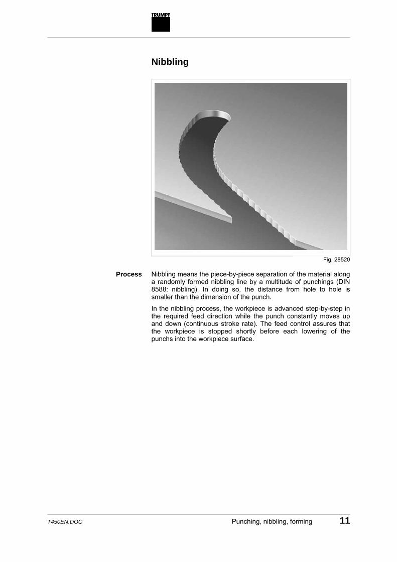
Nibbling means the piece-by-piece separation of the material along a randomly formed nibbling line by a multitude of punchings (DIN 8588: nibbling). In doing so, the distance from hole to hole is smaller than the dimension of the punch.
In the nibbling process, the workpiece is advanced step-by-step in the required feed direction while the punch constantly moves up and down (continuous stroke rate). The feed control assures that the workpiece is stopped shortly before each lowering of the punchs into the workpiece surface.
Fig. 28520
Process

12 Punching, nibbling, forming T450EN.DOC
The next feed step commences as soon as the punch is above the workpiece surface again. Through continuous repetition of this process, the cutting of the required workpiece shape is divided into a score of small, individual cuts.
The size of the individual feed increments is determined primarily by the following factors: • Type and size of applied tool. • Required quality or roughness tolerance of nibbled edge.
The maximum acceptable feed step depends on the material thickness and the stroke rate of the ram. More information on the selection of the suitable feed step can be found in the appendix. The fact that the cutting process is divided into partial cuts in rapid succession, using a simple tool, makes nibbling particularly suitable for the following tasks: • Fabrication of cut-outs and contours of any size and shape
which, due to the punching capacity of the machine, cannot be made in one single downstroke of the ram: – Because the required size is over the max. outer
circlediameter of the tool of 76.2 mm. – Because the max. punching capacity of the machine would
be exceeded. • Production of cut-outs that are irregular in shape and for which
a special tool capable of making the cut-outs in one downstroke of the ram would be too time-consuming or too costly.
• The required number of tools for a job can often be reduced by applying the nibbling process instead of the punching process for break-throughs. This often results in time-saving advantages in the production process.
Generally speaking, all TRUMPF punching tools can be used for nibbling. It is best, however, to use tools with punch diameters or punch edge lengths between 4 and 30 mm.
Punching tools which are primarily used in nibbling operations, especially those applied for machining thicker sheets or those of a higher tensile strength, are available in the following versions: • Special materials, e.g. HSS (super-speed steel). • Coatings, e.g. TICN (titanium carbonitride).
This is why a much higher tool life is reached.
Applications, advantages
Nibbling tools

T450EN.DOC Punching, nibbling, forming 13
Forming
Example: extruding There are various processes for forming by which the sheet is changed by plastic deformation. Examples of forming are extruding, louver cutting, beading, and tapping. There are other processes, as well as forming, that can be applied on a punching machine: • Marking • Embossing • Punch marking.
Fig. 28521
Process
More processes

14 Punching machine concept T450EN.DOC
2. Punching machine concept
2.1 Components of a punching machine
11
12
9
10
1
23
4
14
13
6
5
87
1 Machine table 6 Hydraulic unit 11 Tool rotation 2 Ram 7 Transverse rail 12 Shavings and punching slugs 3 Ram control 8 Linear magazine 13 Workpiece 4 Workpiece clamps 9 Tools 14 Parts flap 5 C-frame 10 Sheet
Statement of principle
Fig. 28522

T450EN.DOC Punching machine concept 15
C-frame
FEM-calculated C-frame The C-frame retains the forces needed for punching. It is constructed in a C form and is opened at the front. The C-frame allows good access to the working range, and the machining of oversized sheets by rotating.
Fig. 25888
C-frame

16 Punching machine concept T450EN.DOC
Hydraulic punching head
The punching head is the center piece of a TRUMPF punching machine. The hydraulic punching head operates power- and energy-optimized. The required punching force stage is automatically selected depending on the required punching capacity. The hydraulic ram has its own NC-axis, which automatically adjusts the start point and reversing point of the ram movement to the material thickness. A hydraulic pump generates the required oil pressure (up to 230 bar), which is converted to a punching stroke via a cylinder. Stroke rates up to 1200 min-1 are possible today. More extensive information on the operation of the hydraulic punching head can be found in the appendix.
Fig. 28800
Center piece of the punching machine
Hydraulic ram
T450EN.DOC Punching machine concept 17
Tool adapter
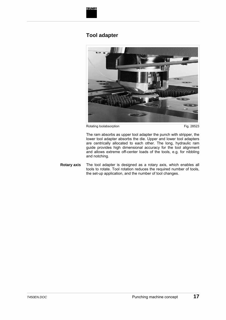
Rotating toolabsorption The ram absorbs as upper tool adapter the punch with stripper, the lower tool adapter absorbs the die. Upper and lower tool adapters are centrically allocated to each other. The long, hydraulic ram guide provides high dimensional accuracy for the tool alignment and allows extreme off-center loads of the tools, e.g. for nibbling and notching. The tool adapter is designed as a rotary axis, which enables all tools to rotate. Tool rotation reduces the required number of tools, the set-up application, and the number of tool changes.
Fig. 28523
Rotary axis

18 Punching machine concept T450EN.DOC
Linear magazine
The required tools for machining are housed in the linear magazine (Linear magazine). They are manually engaged in the specified positions or transferred automatically using the external tool memory ToolMaster 40/70. The linear magazine is mounted along the transverse rail, and uses the available motion axes. A set of tools required for machining is inserted into the tool adapter of the punching head by means of a process programmed through the coordinate guide – and thus the linear magazine. As well as the tools, clamps are also integrated in the linear magazine for clamping the workpiece.
Fig. 47129
Absorption of tools and workpiece clamps

T450EN.DOC Punching machine concept 19
Coordinate guide
The sheet held by the clamps is positioned by a program-controlled coordinate guide in longitudinal and transverse directions during machining. Rack and pinion systems execute the travel motion. High-dynamic drives provide for positioning speeds of up to over 100 m/min.
Fig. 26181
Positioning the sheet

20 Punching machine concept T450EN.DOC
Machine tables
Y
X
The machine tables serve to provide support for the sheet during machining. The (where possible) complete support reduces the vibrations and the sagging of the sheet when positioning. The machine tables are designed to be moved in the Y-direction. Ball rollers or brushes, which are integrated in the table surface, assure non-scratch machining of the sheet. CNC control
Several machining functions and the positioning of the sheet are CNC-controlled. The CNC control coordinates the drives to ensure the synchronization of separate travel motions and the exact align-ment from the coordinate guide (workpiece positioning) and ram (punching stroke).
Fig. 28752
Supporting the sheet
Coordinating the drives

T450EN.DOC Punching machine concept 21
2.2 Punching
Machine loading
Before machining, the operator loads the linear magazine with tool cartridges which already include combined tools for tool sets. He then brings the raw sheet to the machine tables where the sheet is clamped by clamps. The previously created program (e.g. with the help of TruTops Punch) is called up at the control system. It is recommended to specify to the supplier general details regarding evenness, dimensional accuracy, storage, and quality before ordering the raw sheets. The DIN norms concerned are DIN EN 10131/10029/10051 and DIN EN 10130. To simplify the insertion of the raw sheet in brush tables, large-size sheets or thick sheets, liftable ball rollers can be activated, as an option, in the machine tables on which the sheet can roll when inserting. Program execution
TruTops Punch implementation It is mostly the case that several, often identical, parts are pro-duced from one sheet. First, the tool inserted into the tool adapter machines all equal elements of the sheet. Then the next tool is inserted. The machine only separates the single workpieces with a tool when the sheet has been completely machined.
Sheet quality
Loading-/unloading aid
Fig. 28548

22 Punching machine concept T450EN.DOC
Program execution is already optimized in speed and efficiency during sheet programming: • If forming is to be carried out, the variable forming height of the
ram should be used. This enables the formed areas to be passed along with minimal distance.
• When producing continuous formed areas, e.g. beading, you should make sure that in thin sheet the sheet is always machined near a tensile force, i. e. the machining should, if possible, take place close to the clamps due to stability reasons. Furthermore, it is recommended, e.g. for creating circles, to program two overlapping semi-circles so that pushing the sheets together is avoided.
• If noise reduction and, therefore, the use of Whisper tools is not necessary, then flat punches can be used for quicker machining.
• When repositioning, you should always make sure that the sheet is fixed centrally, so that inaccuracies due to unsym-metrical clamp positions are avoided.
The following measures frequently result in shorter processing times for machines with automation: • Under certain circumstances, the "peel off" function can be
ignored for greater material thicknesses and grease-free sheets.
• Trimming should always be carried out on the left-hand side. The (L-shaped) sheet skeleton can thus be securely gripped from the right using the GripMaster 500/5000 grippers.
• Thin sheets can be distorted when inserting with SheetMaster. Increased safety and accuracy is reached when using the "Relieve sheet" function. At the same time, the clamps are opened again and then closed so that the sheet is relieved of pressure.
Optimization measures
Automation

T450EN.DOC Punching machine concept 23
Part removal
Programmable parts flap Fixed chutes and a programmable parts flap enable the quick removal of finished parts and waste parts out of the working area of the machine after machining. The following measures can be taken with a view to quick removal and to shorten the whole processing time: • A row-by-row push-out after the last stroke respectively (for
grid machining) with an open parts flap reduces the push-out time. In doings so, the parts sensor should be activated for safety reasons.
• The removal of the parts can also be carried out with the ram in the highest position. Due to its own weight pushing it forward, the respective part falls unimpeded into the bucket or onto a conveyor belt.
• Cut-out punching of the sheet skeleton in non-automatic machining can be a practical alternative to manual removal if the parts geometry, material thickness are suitable, and according to how the sheet is used. Cut-out punching, for example, is practical for straight parts in thin metal.
Fig. 26183
Optimization measures

24 Punching machine concept T450EN.DOC
The following measures normally lead to shorter processing times for automatic machines: • First, the large finished parts should be removed using
SheetMaster. Whilst the smaller parts are then removed through the parts flap or chutes, the SheetMaster can prepare a new raw sheet.
• SheetMaster should remove the parts in sequence from left to right so that collisions are prevented with free-punched, but not yet removed parts.
Sheet skeletons and waste parts should be sorted, according to the class of material, into containers ready for picking up.
Automation
Unloading

T450EN.DOC Punching machine concept 25
Clamp dead areas
Caused by the geometrical dimensions of the tool adapter and clamps, areas are established in the immediate proximity of the workpiece clamps, where machining cannot be carried out. These so-called clamp dead areas must be observed without fail when programming. This not only applies to feeding break-throughs and contours to the sheet, but also to the approach of positions close to the clamp dead area.
72
97 97
1 2
1 Clamp 2 Dead area
The process with opened clamps, e.g. when repositioning, is only permitted outside the dead area in the X-direction. This means a minimum strip width of 85 mm is required along the linear magazine. Multitools bring about larger clamp dead areas due to the eccentric arrangement of their single tools. Multitool Outer circle
diameter Dead area in X-direction
Dead area in Y-direction
5-fold 20 mm 234 mm 92 mm 10-fold 26 mm 246 mm 98 mm
Dead areas when multitools are used
Dead areas for closed clamps
Fig. 28526
Dead area for open clamps
Dead areas when multitools are used
Tab. 2

26 Punching machine concept T450EN.DOC
Repositioning
Repositioning can be necessary for: • Machining sheets of excessive length. • Machining in the clamp dead area. Repositioning can be carried out: • By using the active presser foot. The sheet is clamped under
the punching head with the aid of the presser foot whilst the opened clamps travel. Prerequisite is that a punching tool is inserted for the deselected forming height (raised ram position).
• On some machines with an optional repositioning cylinders. These clamp the sheet whilst the opened clamps travel.
If formed areas are present in the sheet, you must make sure that these are not damaged when repositioning. Two strategies prevent collisions with formed areas: • Punch machining is carried out after repositioning and from the
forming height. • A forming tool is used after repositioning. Automatic acceleration programming
The acceleration values of the axes have been optimized in favor of a considerable increase in productivity with the newest TRUMPF punching machines (TruPunch 5000). The considerable influence the masses to be moved have on the acceleration was the reason for this optimization. This was a success by adjusting the acceleration values to the respective machining situation: • The number of loaded tools and clamps is recorded in weight. • The cartridge type (metal or RTC (Rapid Tool Change)) is
recorded in weight. • The current sheet weight is continuously recorded during
machining, i. e. the more parts that are separated, the lighter the sheet.
the recorded values are calculated to the advantage of the highest possible acceleration.
Application
Two options
Formed areas
Considerable increase in productivity

T450EN.DOC Punching machine concept 27
2.3 Tool management
The fully automatic execution of a program through the punching machine requires loading the correct tools from tool storage into the linear magazine. For this purpose, the tools are managed in table work.
The tool setup list is generated by pressing a button for the NC program to be executed. The tools are displayed in the tool setup list with all identification characteristics such as ID number, tool dimensions, tool station etc.
A tool setup list can also be created for the loading of the external tool memory ToolMaster 40/70.
Tool setup list
Fig. 28804

28 Punching machine concept T450EN.DOC
All tools which are needed for the execution of an NC program are entered in the tool requirements list. The operator can have displayed which and how many various tools must be available. Further lists show the tool changed and the identification characte-ristics of not only single tools, but all tools in overview. The lists can be edited directly.
Tool requirements list
Fig. 26739

T450EN.DOC Punching machine concept 29
2.4 Automation
Due to the embedding in a system of automation components, TRUMPF punching machines have become flexible production cells. The automation inside the production cell applies to the tool handling and the material handling. Regardless of the raw sheet blanks, the batch size, and the dimensions of the assembly units, the automation components support the entire spectrum of machining possibilities.
1
2
3
4
5
6
TruPunch 5000
XtoolMaster 40
1 SortMaster Pallet sorting unit 2 SheetMaster 1305/1605 for loading
and unloading
3 SortMaster Box sorting unit 4 GripMaster 5000 for sheet
skeleton removal
5 ToolMaster 40/70 external tool memory
6 StoreMaster
Example: TruPunch 5000 automation Fig. 47130

30 Toolsystem T450EN.DOC
3. Toolsystem
1
2
3
4
1 Punch 2 Alignment ring
3 Stripper 4 Die
Complete tool set A punching tool comprises of a punch and die. The alignment ring and stripper complete the tool set. A tool cartridge holds the tool set. Regardless of the tool size, uniform tool cartridges are available as RTC cartridgesn (Rapid Tool Change) or as metal cartridges. The complete tool set can be inserted into the tool adapter of the punching head in one working step. The tools are available in 3 size groups which are designated with 0, I, II. Tools belonging to one particular size group vary only in their cutter geometry and are not identical in construction or clamping range.
Fig. 19173
Tool set
Size groups

T450EN.DOC Toolsystem 31
3.1 Punch with alignment ring
Punch Punches are made of super-speed steel (HSS) and are extremely durable. They can be designed differently: • Uncoated or coated: TICN coated punches are especially
recommended for aluminum- and stainless steelmachining, to prevent cold welding effects and premature wear of the punch.
• For use in particularly thick sheet or in sheets with a high tensile strength, punches can be employed in a stronger version.
• Furthermore, a difference is noted between needle punches and solid punches. Needle punches can be used in thin sheet ranges and are less expensive than solid punches. They are available in 2 versions: for example, round punches with Ø 0.5–6 mm and Ø 6–10.5 mm.
1 2 1 Needle punch 2 Solid punch
Versions
Fig. 28528

32 Toolsystem T450EN.DOC
2
1
1 Punch chuck 2 Needle punch
Structure of needle punch Solid punches and needle punches can be reground by max. 3 mm. • Tools with angled punches are called Whispertools:
– They have a reduced cutting force requirement for the same punch dimensions.
– The noise reduction is up to 50 %. – Whispertools are particularly effective when machining
high-strength and tough materials. – The shearing angle is α 5° up to a diameter of 35 mm, the
height h is variable. As from a diameter of 35 mm, the height of the shearing bevel is 3 mm, the angle is variable.
α h hα
α Shearingäangle h Height of the shearing
bevel
Flat, Whispertool, and roof shear
– Alternatively, punches with roof shears can be used. The off-center load is lower with these tools than with Whispertools.
Fig. 28801
Regrinding
Whispertools
Fig. 19172

T450EN.DOC Toolsystem 33
1 2 3 1 Flat punch 2 Angled punch (Whispertool)
3 Punch with roof shear
The current TRUMPF punching machines can be equipped with long punches. Flat punches (and also needle punches) are 3.5 mm longer than before. The previous short punches can, however, also be used.
34.3
mm
(37.
8 m
m)*
37.3
mm
1 2
1 Flat punch ()* Dim.: long punch
2 Angled punch (Whispertool)
• The usefulness of the new punch lays in the deployment of the
active presser foot: machining with an active presser foot is carried out with a punch in its new state almost as fast as in operation with a passive presser foot.
• Regrinding: the new, long punches can be reground by up to 6.5 mm, angled punches (Whispertools) by up to 3 mm. Make sure you observe with long punches that the punch diameter is slightly reduced the more it is reground; this is due to technological reasons concerning the clearance angle on the punch.
• If a longer punch has been reground more than 3.5 mm, it can also be used on a TC 500 R, TC 200 R or TC 600 L.
Fig. 28529
Long punch
Fig. 19501
34 Toolsystem T450EN.DOC
1
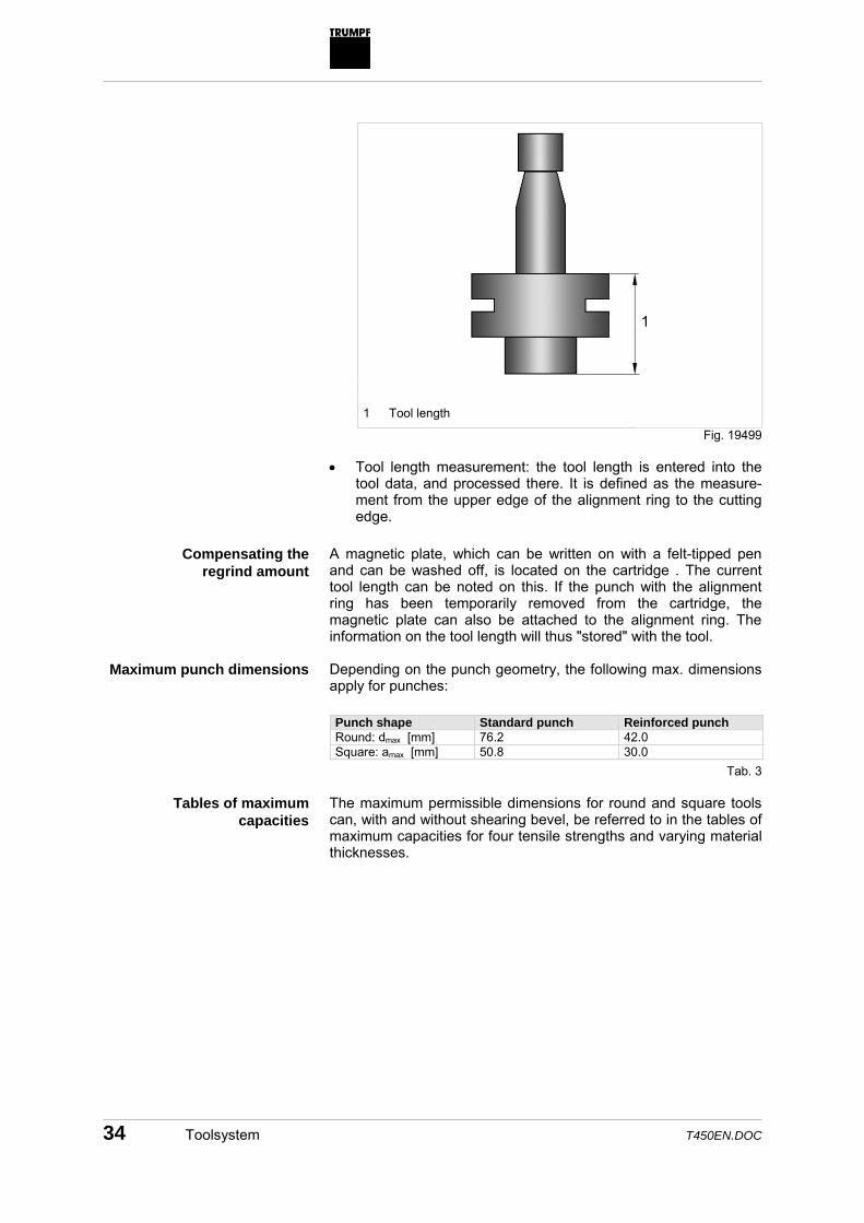
1 Tool length
• Tool length measurement: the tool length is entered into the
tool data, and processed there. It is defined as the measure-ment from the upper edge of the alignment ring to the cutting edge.
A magnetic plate, which can be written on with a felt-tipped pen and can be washed off, is located on the cartridge . The current tool length can be noted on this. If the punch with the alignment ring has been temporarily removed from the cartridge, the magnetic plate can also be attached to the alignment ring. The information on the tool length will thus "stored" with the tool. Depending on the punch geometry, the following max. dimensions apply for punches: Punch shape Standard punch Reinforced punch Round: dmax [mm] 76.2 42.0 Square: amax [mm] 50.8 30.0
The maximum permissible dimensions for round and square tools can, with and without shearing bevel, be referred to in the tables of maximum capacities for four tensile strengths and varying material thicknesses.
Fig. 19499
Compensating the regrind amount
Maximum punch dimensions
Tab. 3
Tables of maximum capacities

T450EN.DOC Toolsystem 35
The values given in the tables of maximum capacities are standard values which, above all, are influenced by the following factors: • The material thickness can, in accordance with DIN EN 10131/
10029/10051, can include tolerances of up to +18 % upwards. • The tensile strength can, in accordance with DIN EN 10130,
reach up to +12.5 %. • The reduction of the clearance between punch and die from
10 % to 5 % of the material thickness induces an increase of the required punching capacity by approx. 4 %.
• Lubricating the workpiece reduces friction. • The shear factor is calculated theoretically, and is also
influenced by the workpiece characteristics. • The sharpness of the punch. In practice, this means: if all the unfavorable factors are multiplied with each other, then only approx. 70 % of the given values should actually be used to ensure that the punching-through operation can be carried out.
Influencing factors
36 Toolsystem T450EN.DOC
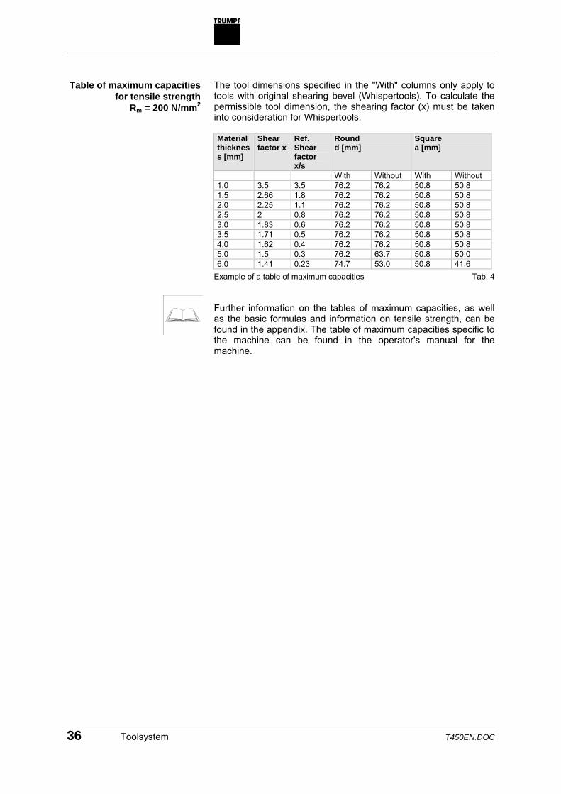
The tool dimensions specified in the "With" columns only apply to tools with original shearing bevel (Whispertools). To calculate the permissible tool dimension, the shearing factor (x) must be taken into consideration for Whispertools. Material thickness [mm]
Shear factor x
Ref. Shear factor x/s
Round d [mm]
Square a [mm]
With Without With Without 1.0 3.5 3.5 76.2 76.2 50.8 50.8 1.5 2.66 1.8 76.2 76.2 50.8 50.8 2.0 2.25 1.1 76.2 76.2 50.8 50.8 2.5 2 0.8 76.2 76.2 50.8 50.8 3.0 1.83 0.6 76.2 76.2 50.8 50.8 3.5 1.71 0.5 76.2 76.2 50.8 50.8 4.0 1.62 0.4 76.2 76.2 50.8 50.8 5.0 1.5 0.3 76.2 63.7 50.8 50.0 6.0 1.41 0.23 74.7 53.0 50.8 41.6
Example of a table of maximum capacities Further information on the tables of maximum capacities, as well as the basic formulas and information on tensile strength, can be found in the appendix. The table of maximum capacities specific to the machine can be found in the operator's manual for the machine.
Table of maximum capacities for tensile strength
Rm = 200 N/mm2
Tab. 4

T450EN.DOC Toolsystem 37
The following table gives an overview of the main application ranges of normal punch versions. Please observe the punching capacity and the maximum permissible material thickness of your machine.
Punch type Max. punching capacity
Max. material thickness Material
Punching Nibbling Flat punch, size 0: up to 6 mm outer circle Ø 6-10 mm outer circle Ø
50 kN 50 kN
Mild steel : 4 mm Stainless steel : 2 mm Mild steel : 6 mm Stainless steel : 3 mm
Mild steel: - Stainless steel: - Mild steel: 3 mm Stainless steel: -
HSS HSS HSS HSS
Flat punch, size I (max. outer circle Ø: 30 mm)
200 kN
10 mm
Mainly for nibbling up to 10 mm
HSS
Flat punch, size I/II (max. outer circle Ø: 76.2 mm)
300 kN
12 mm
As from 10 mm
HSS oxidized
Whispertool 200 kN 10 mm For tensile strength of 400 N/mm2 to 3 mm For tensile strength of 800 N/mm2 to 2 mm
HSS
Alignment ring
The alignment ring is a clamping ring which holds the shape punch (e.g. rectangular tool) in the zero position. The alignment ring fulfills the following functions: • Transferring the punching capacity to the punch. • Allocating the relative position of the punch and retaining. • Adapting different punch sizes. • Holding the punch in the cartridge.
Application range
Tab. 5
Fig. 19505
Function

38 Toolsystem T450EN.DOC
There are 3 alignment ring versions: Tool size Size 0/I Size II Size II Application Punching tools Punching tools With oxidized
punches (HSS) Slitting tools Punches with cutter guide
Illustration
Fig. 7133
As from an outer circle diameter of 40 mm, punches with an integrated alignment ring are also available.
Fig. 6

T450EN.DOC Toolsystem 39
3.2 Stripper
The stripper or presser foot can assume three functions: • Stripper function: The stripper strips the sheet on its upstroke
from the punch. This prevents the sheet from being pulled up by the punch. During operation with a passive presser foot, the stripper is located 0.6–1.6 mm above the workpiece surface.
• Presser foot function: If punching with an active presser foot, the stripper rests on the sheet while the punching stroke is executed. This helps to press the sheet against the die under-neath, thereby improving the position accuracy, the quality of the cut, and the evenness. Machining with an active presser foot is carried out in combination with a long tool (tool length 37.8 mm) almost as quick as operation with a passive presser foot.
• Holding the workpiece: for repositioning oversized sheets, the stripper is lowered directly onto the sheet, and clamps it while the coordinate guidance travels with opened clamps for repositioning.
• For pushing out thin sheets, TRUMPF recommends the use of specially sprung push-out strippers.
Caution
Risk of collision between the old stripper and workpiece! On the newer punching machines, strippers of the older type may not be used as they were for use in the TC 260, for example. The stripper must have similar shear properties as used on the machines TC 200 R, TC 500 R, TC 600 L, TC 2000 R and TruPunch 5000!
Only use the new strippers with shear!
Fig. 19504
Three functions

40 Toolsystem T450EN.DOC
3.3 Die
The punch and die function as shearing tools which move away from each other in opposite directions and cut the sheet. The resulting punching slugs fall through the die and are vacuumed. Standard dies and reinforced dies are available up to the following maximum sizes: Die shape Standard dies [mm] Reinforced dies [mm] Round: dmax 77.0 62.0 Square: amax 52.0 43.0
Die size Standard dies [mm] Reinforced dies [mm] I 18 - II 20 29
Die size Die version Round d
[mm] Square a [mm]
Max. punching capacity [kN]
I All Up to 32.0 Up to 22.0 250 II Standard 32.01 – 77.0 22.01 – 52.0 180 II Reinforced 32.01 – 62.0 22.01 – 43.0 250
• Special slug retaining dies (see p. 3) prevent the punching
slugs being pulled up and causing scratches on the sheet surface during the upstroke of the punch.
• Dies with brush inserts also reduce the scratch formation. When selecting the suitable, the material thickness to be machined must also be observed. A larger clearance between the punch and die is needed the more the material thickness increases.
The die geometry to be chosen is calculated as the sum from punch geometry (DSt) plus the practically established value 0.2 x
Fig. 19503
Function
Versions
Tab. 7
Die heights
Tab. 8
Max. punching capacity
Tab. 9
Scratch-free machining
Selecting the suitable die

T450EN.DOC Toolsystem 41
material thickness (s). Consequently, for round tools this leads to the calculation: ∅Die = ∅Punch + 0.2 x Material thickness Other geometries are to be handled accordingly. Dies can be reground by a max. of 1 mm. Reground dies are placed underneath the tool adapter with shims (0.1, 0.3, 0.5 mm).
Regrinding

42 Toolsystem T450EN.DOC
3.4 Criteria for toolselection
Tools and workpiece
When punching, punching tools bring holes and break-throughs of varying shape into the workpiece. The most normal tool shapes are round-, square-, rectangular- and oblong tools. The outer contour of a single part can be machined with punching tools or with slittingtools according to the contour run.
The minimum dimension of a blanking punch is calculated according to the rule-of-thumb: Punch dimension (outer circle diameter) ≈ material thickness. There is a danger the punch will break in the event a smaller dimension is applied. To prevent the punch from breaking however, tools with a cutter guide can be used or work must be carried out using an active presser foot. The maximum punch dimension of a blanking punch is dependent on the following influencing factors: • The maximum punching capacity available. • Material thickness. • Tensile strength of the sheet. For nibbling, the following recommendations for the tool dimensions of round or square punches apply depending on the material thickness: Material thickness
Round punch Square punch
s [mm]
dmax [mm]
dmin [mm]
amax [mm]
amin [mm]
8 12 12 12 12 6 12 12 12 12 5 14 10 14 10 4 16 10 16 10 3 20 8 20 8 2 24 6 20 6 1 30 4 20 4
Tensile strength The tensile strength Rm of the workpiece to be machined plays an important part in the tool selection. The most important materials with their tensile-strength range are shown in the appendix.
Minimum punch dimension
Maximum punch dimension
nibbling punch
Tab. 10
T450EN.DOC Toolsystem 43
Tools and machining quality
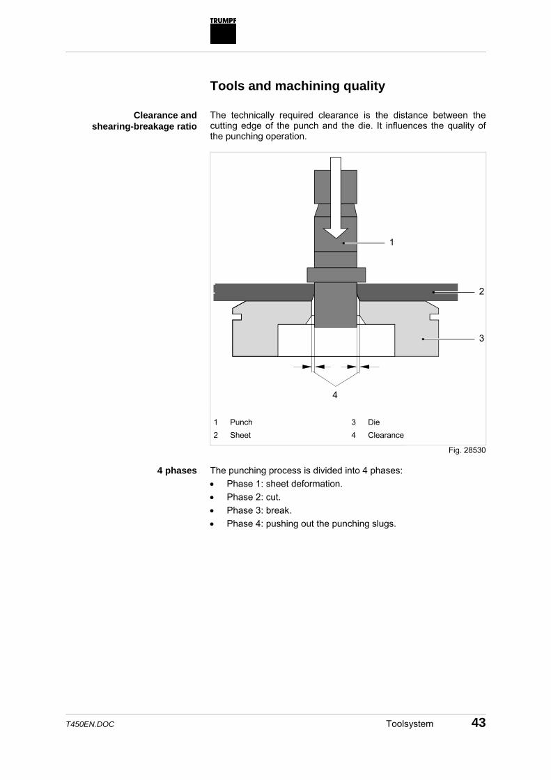
The technically required clearance is the distance between the cutting edge of the punch and the die. It influences the quality of the punching operation.
1
2
3
4 1 Punch 2 Sheet
3 Die 4 Clearance
The punching process is divided into 4 phases: • Phase 1: sheet deformation. • Phase 2: cut. • Phase 3: break. • Phase 4: pushing out the punching slugs.
Clearance and shearing-breakage ratio
Fig. 28530
4 phases

44 Toolsystem T450EN.DOC
2
4
1
3
4 phases of the punching process The selection of the die, and hence the clearance, affects the cut-breakage ratio (phase 2 and 3) when punching. For a clearance of 0.1 x material thickness, the ratio of cut to breakage quota amounts to 1/3 to 2/3. If the clearance is smaller, then the cut quota increases to 2/3.
Fig. 28531

T450EN.DOC Toolsystem 45
Example for 2/3-cut quota The larger the cut quota, the more cylindrical is the punching operation, which can be necessary, e.g. for fits with a very high percentage contact area. The greatest possible cut quota can be reached if the sheet is prepunched with a tool approx. 1-2 mm smaller and with a clearance of 0.1 x material thickness, and then repositioned using the desired tool to create a scraping cut with a small clearance. This procedure has also proven its value for punching capacity minimizing during thick sheet machining with large tools. When machining stainless steel and aluminum, cold welding effects and built-up edges can arise. These effects can be reduced by employing two measures: • Additional lubrication of the tool. • Use of oxidized or coated punches. When punching with an active presser foot, the stripper/presser foot contacts the sheet during the punching stroke. In doing so, the sheet is pressed against the die laying underneath it, which results in very accurate punching operations of level workpieces and an improvement of the quality of cut. If a contour, e.g. a circle, is nibbled using round tools, the nibble edge shows a roughness which correlates with the selected feed rate per stroke. If the feed rate is low, the quality of the nibble edge will improve, i. e.: the roughness is less. Another quality criterion is the heat transmission from the ram and C-frame. It must be taken into consideration especially when programming embossing and forming. During machine operation, the C-frame and ram stretch by a total of 0.1–0.3 mm, i. e., the ram position must be programmed higher. Further information on roughness and on the feed-rate values, as well as the basic formulas, can be found in the appendix.
Fig. 28532
Punching operations with very level cutting surface
Machining stainless steel and aluminum
Manufacture of very exact punching operations
Roughness
Heat transmission

46 Toolsystem T450EN.DOC
Tools and company requirements
In general, a service life of 400 000 up to 600 000 strokes applies to punching tools. The requirements needed to reach this service life are: • A stable tool guide. The long, hydraulic guide of the ram
assures ahigh dimensional accuracy of the tool allocation. • Material-specific lubrication of the tool. • Sharp cutting edge. The required sharpness of the cutting
edge can only be guaranteed by regrinding. • Exact centric alignment of punch and die. For punches with an angled cutting surface (Whispertool), the punching-capacity requirement is reduced by the passing run-off in power when the punch is lowered into the workpiece.
The lower punching capacityrequirement causes noise to be reduced by approx. 50 % in comparison to a punch with a flat cutting surface. The maximum material thickness machined is lower, however. 3.5 Tooltypes
TRUMPF punching tools can be divided into 5 groups. The groups are defined via their technology: • The most frequently used tools are the standard tools (e.g.
round tools), which are allocated in punching technology. They have been described comprehensively in the previous sections. Furthermore, special tools such as multitools and shaped tools are also allocated to this group.
• Special tools for separating produced single parts are compiled in the slitting group.
• The most extensive group of tools can be found in the forming group. Forming tools are described in several separate techni-cal infos.
• The technologies marking, embossing, and tools for scratch-free machining complete the spectrum of tools.
• Special tools are customized and can be defined freely (in limits). Several special tools have been standardized due to corresponding demand.
Service life
Whispertool

T450EN.DOC Toolsystem 47
Technology Tool type Punching Standard tool:
Round tools Square tools Rectangular tools Oblong tools Special tools: Push-out tools Banana tools Shaped tools Multitool tools Punch with cutting edge guide Special tools
Slitting Slitting tools Microjoint tools Special tools
Forming Folding tools Countersink tools Sheet tapping tools Flanging tools Single louver cutting tools Continuous louver cutting tools Tapping tools Hinge tools Boss welding tools Countersink shaped tools Centering dimple tools Extrusion tools Beading tools Special tools
Marking, embossing Punch-mark tools Marking tools Embossing tools Special tools
Scratch-free machining Extrusion tools with brushes Upstroke tools Dies with brushes Parting dies with brushes Intermediate rings with brushes
Special tools e.g. Keyhole tools More detailed information on the single tools can be found in the numerous tool infos, in technical information, and in the electronic punching tool catalog.
Tab. 11

48 Toolsystem T450EN.DOC
3.6 Toolcare
Sharpening tools
QuickSharp QuickSharp is a grinding machine on which the punching tools can be reground. Dies, as well as flat and angled punches can be reground.
QuickSharp is completely encapsulated and allows operation in the immediate proximity of the punching machine.
The grinding process runs automatically. Due to a precise column guide, QuickSharp enables a high-precision regrind for the tools by the operating personnel while the punching machine is in operation. Regrinding is carried out in the wet regrinding process with a boron nitride grinding wheel.
Fig. 47131
Function
T450EN.DOC Toolsystem 49
Setting tools with QuickSet
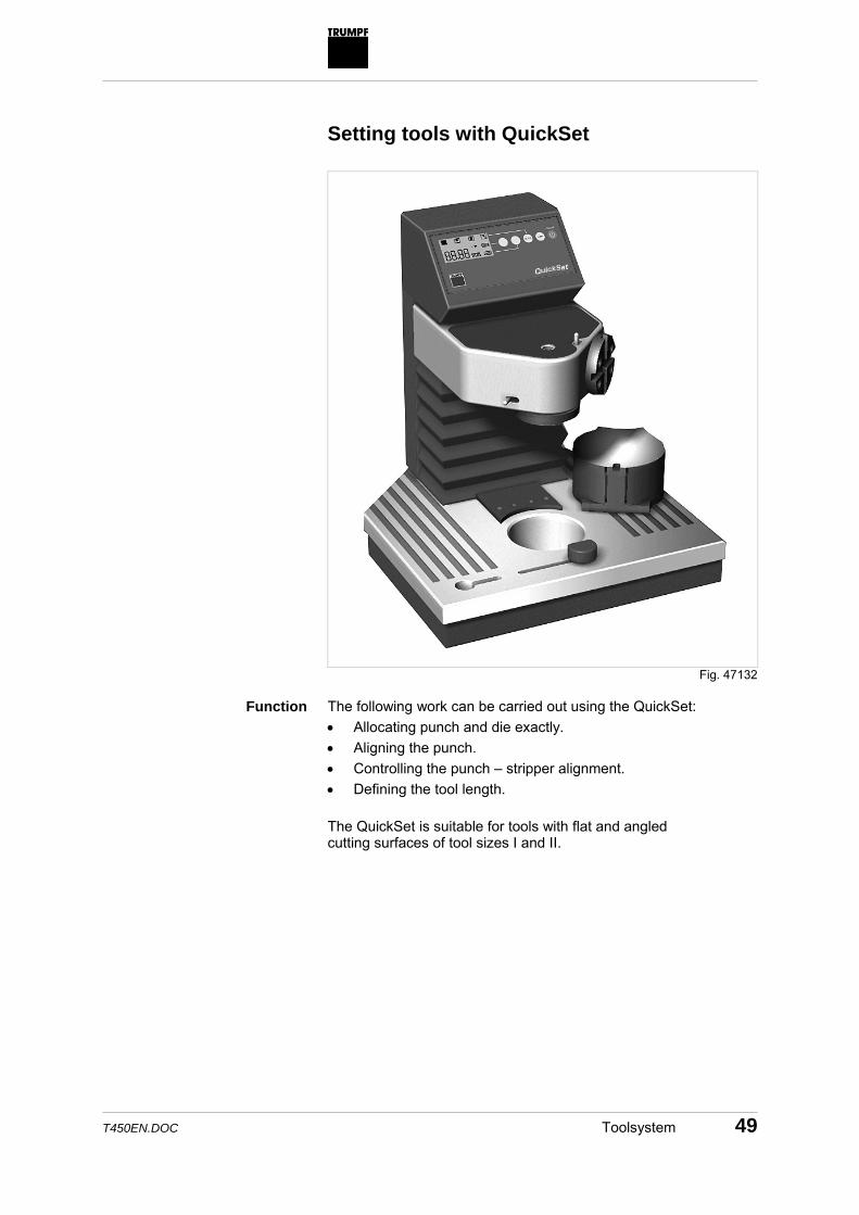
The following work can be carried out using the QuickSet: • Allocating punch and die exactly. • Aligning the punch. • Controlling the punch – stripper alignment. • Defining the tool length. The QuickSet is suitable for tools with flat and angled cutting surfaces of tool sizes I and II.
Fig. 47132
Function

50 Toolsystem T450EN.DOC
Setting tools with setting fixture
The following work can be carried out using the setting fixture: • Allocating punch and alignment ring exactly. • Defining the tool length. The setting fixture is suitable for tools with flat and angled cutting surfaces of tool sizes I and II.
It is included in the scope of delivery for the newer punching machines.
Fig. 21328
Function
T450EN.DOC Toolsystem 51
Loading tools with QuickLoad
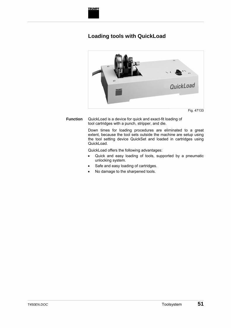
QuickLoad is a device for quick and exact-fit loading of tool cartridges with a punch, stripper, and die.
Down times for loading procedures are eliminated to a great extent, because the tool sets outside the machine are setup using the tool setting device QuickSet and loaded in cartridges using QuickLoad.
QuickLoad offers the following advantages: • Quick and easy loading of tools, supported by a pneumatic
unlocking system. • Safe and easy loading of cartridges. • No damage to the sharpened tools.
Fig. 47133
Function

52 Toolsystem T450EN.DOC
Sticking tools with adhesive pads
QuickPad QuickPad is a gluing device, which enables adhesive pads to be mounted easily onto dies, intermediate rings, and strippers.
Adhesive pads serve to prevent scratches on the workpiece. Adhesive pads are fabricated, self-adhesive polyethylene films with a thickness of 0.3 mm; they are available in different versions according to shape and size of the die (see section 5.2, p. 3). The basic equipment for QuickPad includes a press-set for strippers. In addition, press-sets are available for dies and press-sets for intermediate rings.
Fig. 47134
Function

T450EN.DOC Toolsystem 53
Storing tools
Cartridge trolley The cartridge trolley allows assembly of tools, which are required for a machining program, without being bound to a certain position. It can also be used as an intermediate storage place for tools.
The numbering of the upper level (15 positions) and the lower level (5 positions) enables direct alignment to the tool cartridge positions of the punching machine.
As an additional option, the cartridge trolley offers space to accom-modate technical drawings.
Fig. 28535
Function
54 Toolsystem T450EN.DOC
3.7 Toolcatalog
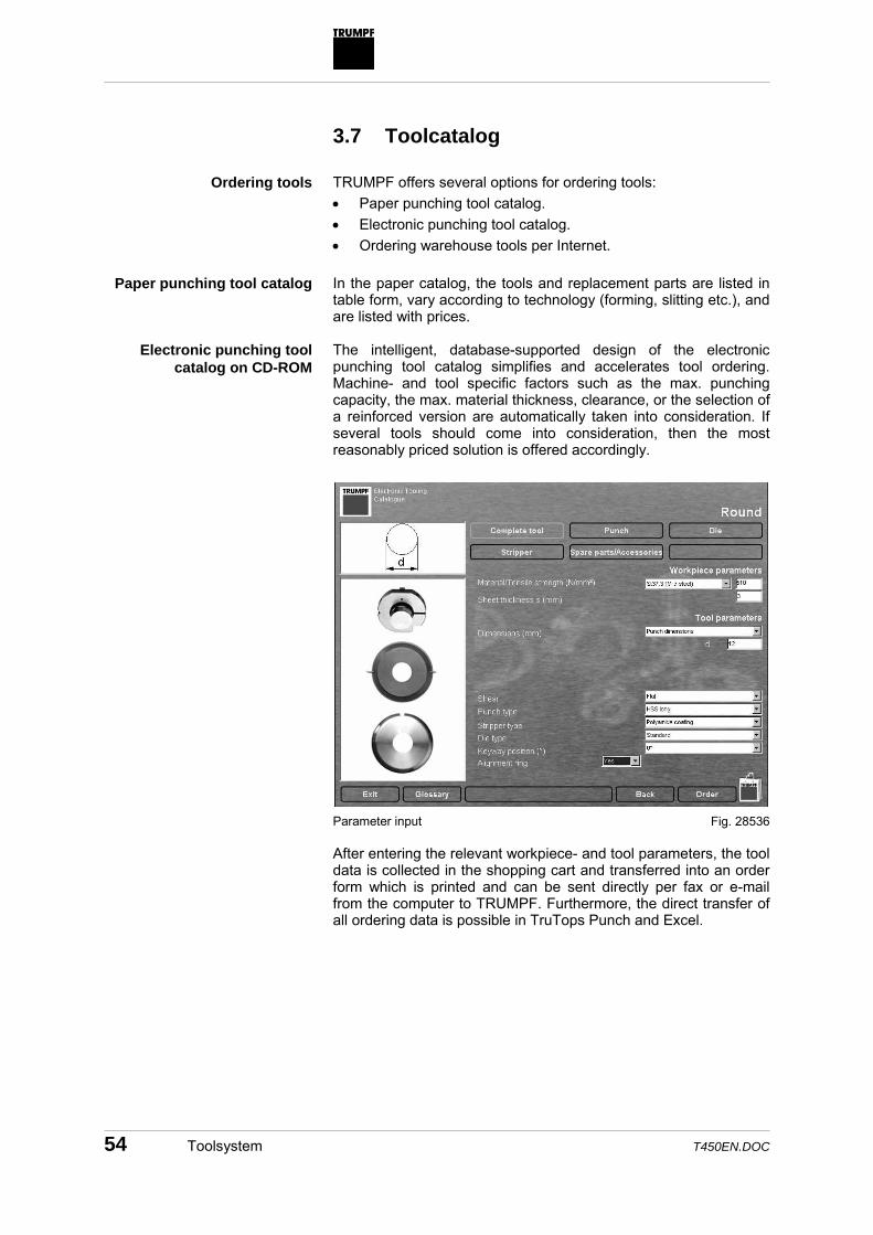
TRUMPF offers several options for ordering tools: • Paper punching tool catalog. • Electronic punching tool catalog. • Ordering warehouse tools per Internet. In the paper catalog, the tools and replacement parts are listed in table form, vary according to technology (forming, slitting etc.), and are listed with prices. The intelligent, database-supported design of the electronic punching tool catalog simplifies and accelerates tool ordering. Machine- and tool specific factors such as the max. punching capacity, the max. material thickness, clearance, or the selection of a reinforced version are automatically taken into consideration. If several tools should come into consideration, then the most reasonably priced solution is offered accordingly.
Parameter input After entering the relevant workpiece- and tool parameters, the tool data is collected in the shopping cart and transferred into an order form which is printed and can be sent directly per fax or e-mail from the computer to TRUMPF. Furthermore, the direct transfer of all ordering data is possible in TruTops Punch and Excel.
Ordering tools
Paper punching tool catalog
Electronic punching tool catalog on CD-ROM
Fig. 28536

T450EN.DOC Toolsystem 55
The required TRUMPF know-how on punching tools is available on this CD-ROM. Extensive information on programming, maintenance, and applications is allocated to the separate tools. Notes on tool care and a www-link to the TRUMPF homepage complement the catalog.
Special tools can be specified on a prepared form, and, where necessary, accompanied by a draft and sent directly to TRUMPF as an inquiry or order. The stock list is highlighted on the TRUMPF homepage. Ware-house parts can be selected here and the order sent directly per e-mail to TRUMPF.
Ordering warehouse parts

56 Quiet punching and nibbling with Softpunch T450EN.DOC
4. Quiet punching and nibbling with Softpunch
4.1 Introduction
The Softpunch option enables considerably quieter sheet machining. Depending on the parameters entered, such as material class and material thickness, a noise reduction of up to 80 % can be achieved. • Due to a pressure sensor mounted on the punching head,
pressure on the upper ramsurface of the punching head is permanently measured. The measured values are compared with the programmed Softpunch stages. The evaluation takes place in the ram control.
• If the measured pressure increases to a defined limit value when the ram contacts the workpiece, the ram speed will be reduced - resulting in much quieter punching through.
• The reduced ram speed has a lower hit rate (stroke rate/min) and, therefore, results in a longer machining time.
• The ram speed is reduced via 4 programmable Softpunch stages: – Largest reduction in ram speed = largest reduction in
noise. – Lowest reduction in ram speed = lowest reduction in noise.
Function
Principle of function
Softpunch stage (S)1
up to Softpunch stage (S)4

T450EN.DOC Quiet punching and nibbling with Softpunch 57
4.2 Comparison: punching and nibbling with and without Softpunch
In fig. 28776, the Softpunch stages 1 to 4 are listed on the X-axis in comparison to machining without Softpunch. The unit sone listed on the Y-axis describes the value of the subjective perception of loudness. This is calculated from the average level LpAeq at the operating site. To illustrate the relation between loudness in sone and noise level in dB(A), several comparative values are listed below. sone dB(A) 1.00 40 8.00 70 16.00 80 32.00 90 64.00 100
Comparative values
Punching
Nibbling E5
0 3 1
310425
200
250
195
240
175
165110
135
10
20
30
0
4 2
Softpunch step
Loud
ness
[son
e]
Material thickness: 3 mm Material: USt12.03
Punch, flat: ∅ 20 mm Die: ∅ 20.4 mm
The diagram illustrates the considerable noise reduction due to Softpunch. The number of ram strokes per minute is noted above every bar.
Tab. 12
Fig. 28775

58 Quiet punching and nibbling with Softpunch T450EN.DOC
4.3 Sequence of a hit rate
The path-time diagram documents the change of the ram speed during a hit rate, without and with Softpunch.
4
3
1 2
56
s [m
m]
t [s]
1 Punching stroke without
Softpunch 2 Punching stroke with Softpunch 3 Working height
4 Lowest position 5 Softpunch stage reached 6 Softpunch stage not reached
Path-time diagram The ram travels from the working height downwards with max. speed to the lowest position, and with max. speed upwards again. The ram travels from the working height downwards with reduced speed until the programmed Softpunch stage (5) is reached (the punch touches the sheet). The actual punching stroke is now carried out with further reduced ram speed. After reaching the changeover point, the starting speed is switched back to. The ram travels in the lowest position and then upwards with max. speed.
Fig. 5273
Punching stroke without Softpunch
Punching stroke with Softpunch

T450EN.DOC Quiet punching and nibbling with Softpunch 59
4.4 Parameters for noise reduction
The effect of Softpunch on noise reduction depends on various parameters: • Tool type (flat or angled). • Material class. • Clearance between punch and die. • Presser foot (active or not active). • Material thickness. Softpunch is effective when flat and angled tools (Whispertools) are used. An optimum noise reduction is reached with a combi-nation of Whispertools with Softpunch, because Whispertools fundamentally enable a quieter machining than flat punches.
Flat punch
Whispertool
0 3 1
10
Softpunch step
Loud
ness
[son
e]
20
30
0
4 2
Material thickness: 3 mm Material: St37.2
Punch: ∅ 20 mm Die: ∅ 20.4 mm
In principle, Softpunch can be applied to every material. However, the effect is dependent on material-specific characteristic values.
For materials of a higher tensile strength (e.g. stainless steel), the noise reduction is, due to the sudden break-through of the punch during the punching process, lower than with materials of an average tensile strength (e.g. mild steel).
By using Whispertools, this can partially be compensated and a similar noise reduction such as in machining mild steel can be reached.
Parameters for tool type
Fig. 28776
Parameters for material class

60 Quiet punching and nibbling with Softpunch T450EN.DOC
The effect of Softpunch on noise reduction can be raised by optimizing the clearance between punch and die. This applies especially for the use of flat punches. When using angled tools, the clearance plays a less important part.
In the diagram, the loudness is documented in relation to the used die (diameter 21.2 and 20.8 mm).
For a smaller clearance, more attention must be paid to adequate tool lubrication.
Die 21.2
0 3 1
20Loud
ness
[son
e]
40
60
0
4 2
Die 20.8
Softpunch step Material thickness: 6 mm Material: MRSt37.2
Punch, flat: ∅ 20 mm Die: ∅ 21.2 mm or 20.8 mm
To gain the greatest effect from Softpunch, it is recommended that you select a smaller than usual clearance between punch and die. When using Softpunch in combination with flat punches, the clearance is calculated according to the formula: ∅Die = ∅Punch + (0.1 to 0.15) x Material thickness Without Softpunch, the normal recommendation for the clearance is: 0.2 x Material thickness Even without Softpunch, noise can be reduced by selecting a smaller clearance.
Parameters for clearance
Fig. 28777

T450EN.DOC Quiet punching and nibbling with Softpunch 61
When selecting the active presser foot in combination with Softpunch, the loudness will be further minimized.
50
40
30
30
10
0
230
215
135120
8580 65
6550
50
0 4 3 2 1
passive
active
Softpunch step
Loud
ness
[son
e]
Material thickness: 6 mm Material: RSt37.2
Punch (Whispertool): ∅ 20 mm Die: ∅ 21.2 mm
One can see from the diagram that a reduction in the ram speed via Softpunch stage 4 results in further reduction of the stroke rate (number above the bar) while the loudness is only minimally reduced.
Parameters for active presser foot
Fig. 28603

62 Quiet punching and nibbling with Softpunch T450EN.DOC
4.5 Table collection
For mild steel and stainless steel, TRUMPF has worked on recommendations for the (S) value for the Softpunch stage, depending on the material thickness, and tested the effect of different Softpunch stages on loudness and stroke rate. The table can be referred to for selecting the respective optimum Softpunch stage. The table points here explicitly to recommendations; varying applications must be adapted accordingly. The details in brackets point to conditional recommendations. Mild steel (USt 12.03)
Material thickness 1–3 mm Softpunch stage Tool Cutting shape Operating mode 1 2 3 4 Round ∅ 12 mm Flat punch
Flat punch Whispertool Whispertool
Punching Nibbling (E3) Punching Nibbling (E3)
x x x x
Round ∅ 20 mm Flat punch Flat punch Whispertool Whispertool
Punching Nibbling (E5) Punching Nibbling (E5)
x (x) x x x
Round ∅ 35 mm Whispertool Punching x Round ∅ 70 mm Whispertool Punching (x) x Round ∅ 75 mm Roof shear Punching x (x) Square 20 mm Whispertool Nibbling (E15) x Slittingtool 5 x 56 mm
Roof shear Slitting (E50) x
Naturally, the loudness can be further reduced for a recommended Softpunch stage 3 or 4 by selecting the Softpunch stage 2 or 1.
Material thickness 4–6 mm Softpunch stage Tool Cutting shape Operating mode 1 2 3 4 Round ∅ 12 mm Flat punch
Flat punch Whispertool Whispertool
Punching Nibbling (E3) Punching Nibbling (E3)
x (x)
x x x
Round ∅ 20 mm Flat punch Flat punch Whispertool Whispertool
Punching Nibbling (E5) Punching Nibbling (E5)
x (x) x
(x) x x
Round ∅ 35 mm Flat punch Punching x Square 20 mm Whispertool Nibbling (E15) x (x)
Tab. 13
Tab. 14

T450EN.DOC Quiet punching and nibbling with Softpunch 63
Stainless steel (1.4301) Material thickness 1–3 mm Softpunch stage Tool Cutting shape Operating mode 1 2 3 4 Round ∅ 12 mm Flat punch
Flat punch Whispertool Whispertool
Punching Nibbling (E3) Punching Nibbling (E3)
x (x)
(x) x x x
Round ∅ 20 mm Flat punch Whispertool Whispertool
Punching Punching Nibbling (E5)
x (x)
(x) x x
Round∅ 70 mm Whispertool Punching x Square 10 x 40 mm Whispertool
Whispertool Punching Slitting (E35)
x x
The operator can switch Softpunch on and off at the machine even during machining.
Tab. 15

64 Punching and nibbling without scratches T450EN.DOC
5. Punching and nibbling without scratches
When a workpiece undergoes punch machining, scratches can result on the surface and underside of the workpiece when machine parts and tools rub against the material. A critical point here is the die, on whose surface microscopic burrs can form and thereby create scratches. In many applications however, such as the production of cover plates which will visible when assembled later, scratches are unacceptable under any terms. Various measures are listed below which allow scratch-free machining. 5.1 Brush tables
The brushes prevent any direct contact between the underside of the sheet and machine components, such as the die, which might cause scratches. The sheet glides over the brushes which, due to their length, yield in the direction of travel, thereby eliminating the track marks which result on the sheet underside on tables fitted with rollers.
Brush tables
Causes of scratches
Consequence
Function
Fig. 15004

T450EN.DOC Punching and nibbling without scratches 65
5.2 Special tools
Adhesive pads
Adhesive pads are fabricated, self-adhesive polyethylene films with a thickness of 0.3 mm. They can be stuck on strippers, interme-diate rings, and dies. An adhesive pad prevents microscopic burrs on the die producing scratches on the underside of the sheet.
1
23
5
6
4
1 Punch 2 Sheet 3 Adhesive pad
4 Die 5 Microscopic burr 6 Punching slugs
Function of the adhesive pad • The sheet is brought into position, the punch is lowered. • The sheet is pressed onto the die, the punching stroke is
executed. • The adhesive pad has the effect of lifting the sheet from the die
after the upstroke. A microscopic burr on the die cannot create any scratches.
Function
Fig. 28537

66 Punching and nibbling without scratches T450EN.DOC
• A: For size I dies, the intermediate ring is affixed with an adhesive pad Ø 62 / 96 mm, and the die set 0.05–0.1 mm below the upper edge of the adhesive pad.
� � � � � � � � � � � � �
• B: Size II dies are affixed with adhesive pads Ø 72 / 96 mm. • C: The illustrated special adhesive pads are available for dies
for rectangular, oblong and slitting tools. • D: The illustrated special adhesive pad is recommended for
square tools measuring 30–50 mm edge length.
• E: Only adhesive pads notched along the perimeter may be affixed to strippers.
� � � � �
� � �
� � � �
1 Intermediate ring 2 Adhesive pad 3 Die, size I
4 Die, size II 5 Stripper
Examples for adhesive pads • Carefully degrease the die, intermediate ring, and stripper
(e.g. with Isopropanol) and remove all old gum residue. • Sharpen the tool where deemed necessary. • Affix the pad, properly centered and air-free. TRUMPF offers
the QuickPad gluing device(see p. 3) for attaching the pads to strippers. Pads can be glued on dies and intermediate rings manually.
• For strippers, the inside contour must be cut out carefully with a sharp knife.
Allocation (Fig. 14754)
Fig. 14754
Procedure

T450EN.DOC Punching and nibbling without scratches 67
• Select elevated working height: Set activity–PRODUCTION–Tables–Sheet technology–Parameter "non-scratch machining" to "1".
The adhesive pads are highly durable depending on the material thickness, how many cut-outs are punched etc. Damage does not impair the scratch prevention properties, except that ragged corners should be trimmed. In the course of a test – material thicknesses 0.5–3 mm, diverse materials, three-shift operation – the adhesive pads were in use for several weeks before they had to be replaced.
Durability

68 Punching and nibbling without scratches T450EN.DOC
Slug retaining dies
Slug retaining dies prevent the slug from being pulled up during the upstroke of the punch. Slug retaining dies have small grooves on the cutting surface. The material "flows" into them due to the force exerted during the punching stroke. If the cohesive force of the punch then pulls the slug up along with it, the latter will be held fast in the grooves, which run in opposite direction. Vacuum slug removal is deacti-vated when working with slug retaining dies. Slug retaining dies can be used for punching but not for nibbling. Angled tools (Whispertools) can be utilized.
�
1 Groove
Slug retaining die Your existing dies can be retrofitted at TRUMPF if they have a minimum inside diameter or side length of 3 mm.
Function
Principle
Fig. 14688
Retrofitting

T450EN.DOC Punching and nibbling without scratches 69
Additional measures
To further reduce scratching, dies and intermediate rings with additional brush inserts are also available.
1
1 Brushes
Die with brush insert Setting: The brushes project about 1 mm above the die surface and bolster the scratch reduction effect described above. In addition, the die has a finely polished surface. Different versions of dies and intermediate rings with brush inserts are available. Multitool dies can be fitted with adhesive padsof Ø 72 x 96 mm. • A modified (downward) extrusion tool is fitted with spring-
loaded brush elements on the die for scratch prevention. • A tool with brush segments on the punch and die can be used
for slitting toolsin formed areas. • Forming tools with a higher ejector, e.g. cupping tools made of
AMCO, can be ordered. AMPCO is a relatively soft alloy whose lubricating effect prevents the ejector from scratching the sheet underside.
Dies and intermediate rings with brush inserts
Fig. 9793
Multitool
Forming tools

70 Punching and nibbling without scratches T450EN.DOC
5.3 The answer: combine different measures
The most effective way to avoid scratches is to use a combination of the following methods: TRUMPF offers two types of machining tables: • Tables fitted with rollers, which have proven most suitable for
working with sheets >3 mm. • Tables fitted with brushes, which have yielded the best results
in scratch prevention when processing sheets <3 mm. Both table versions can be ideally combined with slug retaining dies. The vacuum system for slug removal should be deactivated when working with these dies. Affixing adhesive pads on strippers and dies completes the array of effective measures for scratch-free punching.
For this purpose, select the working height elevated by 1 mm, because the adhesive pads on the stripper and die together are 0.6 mm thick: Set activity–PRODUCTION–Tables–Sheet techno-logy–Parameter "non-scratch machining" to "1". Advantage of the elevated height: larger clearance available for uneven sheets, coupled with reduced wear on the pads.
Roller- or brush tables...
...in combination with slug retaining dies...
...and adhesive pads

T450EN.DOC Punching and nibbling without scratches 71
5.4 Tips for practical operation
• Affix adhesive pads to strippers and dies. • Proper care of tools is of crucial importance. • Clean the following daily: table surfaces, brushes, brush
segments (especially after working sheets with scales), and the sheet support points on the machine.
• You can choose between active or passive presser foot. The
active presser foot holds the sheet down during the punching operation. This prevents scratches being formed due to sheet deformation. Adhesive pads can also be used with the active presser foot.
• Select the working height (stripper 1 mm higher). This helps to
eliminate scratches on the upper side of the sheet caused by the stripper, especially when working uneven sheets.
• Keep tools sharp at all times (QuickSharp). • Use slug retaining dies, turn the slug vacuum off. • Punch and die must be precision aligned to each other to
prevent burring (QuickSet). • Check alignment between upper and lower tool adapter. • Check the setting of the brush fields close to the die; if
necessary, re-adjust or replace. Setting: 0.5–1 mm above the die surface.
• Polish the dies, strippers and repositioning surfaces (grain size min. P360).
• Make sure the brushes are set correctly on the dies and intermediate rings.
• Use polyamide-coated strippers.
Adhesive pads
Daily cleaning
Working with the active presser foot
Elevated working height
Additional measures

72 Punching and nibbling without scratches T450EN.DOC
5.5 Other options
Avoid sheet deformation: • Choose the suitable punches and dies in relation to the
clearance: Tests have shown that both too small and too large a clearance between punch and die lead to increased deformation.
5 10 15 20 25 30 35
1
2 1 Deformation 2 Cutting clearance
(2 x clearance) in % of the material thickness
s = 1.5 mm
• Suitable sequence for tool deployment: e.g. pre-punching a cut
out with square tool, then finishing sequence for cut out using slotting tool.
10
Deformed workpiece due to unfavorable processing sequence • Use active presser foot. • Pre-punching and finish punching: e.g. pre-punch with round
tool Ø 9.8 mm, finish punch with Ø 10 mm. • Row-by-row processing reduces sheet deformation. • Use flat, even sheets (EN 29-81); if necessary, stipulate
tolerance limits that your supplier must meet. • Use sheets that have been stress-relief annealed.
Use level sheets
Fig. 28538
Fig. 5449

T450EN.DOC Punching and nibbling without scratches 73
• Use foil-coated sheets (e.g. polyethylene PE). No adhesive pads are needed in this case.
• Ample tool lubrication prevents cold welding effects, built-up edges on the punch, and premature or excessive burr formation.
• As an additional measure, oil can be brushed on the underside of the sheet (machines with roller tables only).

74 Flatness of sheets during punching and nibbling T450EN.DOC
6. Flatness of sheets during punching and nibbling
6.1 Introduction
When buying the sheets, the evenness is defined according to DIN EN 10051 or DIN EN 10029. Additional deformations can arise when machining the sheet on a punching machine. The degree of deformation increases with the number of punching operations on the sheet.
This results in a loss both in quality and accuracy, requiring refinishing (straightening) and, in extreme cases, a risk of collision at the machine between the sheet and tool. For this reason, it is imperative that the sheet be kept as flat as possible while it is being machined.
The causes of deformation are dealt with below and strategies for reducing deformation are pointed out. 6.2 Causes of deformation
The sheet may become deformed due to strains induced by the punch and die in the immediate proximity of a punching operation. These strains do not spread to the entire sheet.
During the punching process, the material is "compressed" by the punch and die, until the punching capacity is great enough for the slug to break through the die. However, the strains that such "compression" produces in this area of the sheet persist, resulting in deformation. As tests at TRUMPF have shown, the sheet becomes flat again if the area of strain (approx. 1 mm for sheets with material thickness of 2 mm) e.g. is removed by laser cutting.
1
2
34
5
1 Sheet 2 Punch 3 Strains, punching slugs
4 Strains, workpiece 5 Die
Strains
Deformation due to strains
Fig. 28539

T450EN.DOC Flatness of sheets during punching and nibbling 75
The degree of deformation increases with the punching capacity required. Pursuant to this, deformation increases with: • Thick sheets. • Hard material (stainless steel). • Dies that are too small or too large. • Blunt tools. Another cause for deformation is the bowing of the sheet between punch and die during machining. This again results in strains.
1 2 3 1 Sheet 2 Die
3 Punch
Note For better illustration, sheet bowing is exaggerated in Fig. 28540.
Deformation due to bending
Fig. 28540

76 Flatness of sheets during punching and nibbling T450EN.DOC
6.3 Strategies for reducing deformation
Strategies for reducing deformation are described in the following: • Selection of suitable punches and dies. • Strain-free machining through correct choice of tools. • Use of the presser foot. • Pre-punching and finish punching. Selection of suitable punches and dies
The punch must be ground very sharp if the punching force (and consequently the deformation) is to be reduced. Even better results are attained by using Whispertools. Tests have shown that both too small and too large a clearance between punch and die lead to increased deformation. A die which may be ideal for minimizing sheet deformation can however, in unfavorable situations, result in burr formation at the sheet edge. Strain-free machining through correct tool choice
In conventional machining of the sheet in Fig. 5449 (slitting tool, with active presser foot), the deformation is approx. 10 mm.
Material thickness s: 2.5 mm Material: aluminum
Punch: square 10 mm
On the other hand, if the cutouts are prepunched with a 8 mm square tool and then finished with the slitting tool, the resulting deformation is only about 5 mm.
Sharp punches
Clearance
Fig. 5449

T450EN.DOC Flatness of sheets during punching and nibbling 77
Use of the presser foot
Sheet deformation is reduced when the presser foot (stripper) is used, because the presser foot holds the sheet flat down while it is being machined.
Note For soft materials such as copper or aluminum, the presser foot may also produce the opposite effect as it presses the sheet, causing the sheet to bow. On machines where the presser foot pressure can be adjusted, the pressure should be lowered.
The following measures described below boost the effectiveness of the presser foot: • Arching over the sheet. • Use of shims. • Chamfering the die.

78 Flatness of sheets during punching and nibbling T450EN.DOC
This method reinforces the effect of the active presser foot. To do this, the presser foot (stripper) must be able to arch a little over the die. In the process, the sheet is "straightened" by the stripper which bows slightly at its outer ends. A flat stripper is used in this method, with the normal clearance between punch and stripper (approx. 1–2 mm).
F F
1 2 3 4 F Presser foot force 1 Sheet 2 Die
3 Stripper 4 Punch
Note For better illustration, stripper and sheet bowing is exaggerated in Fig. 28542.
Strippers of older design with a thicker base cannot be used.
For the stripper and the sheet to be able to arch over the die, the latter must be raised or chamfered as described in the following.
Arching over the sheet
Fig. 28542
T450EN.DOC Flatness of sheets during punching and nibbling 79
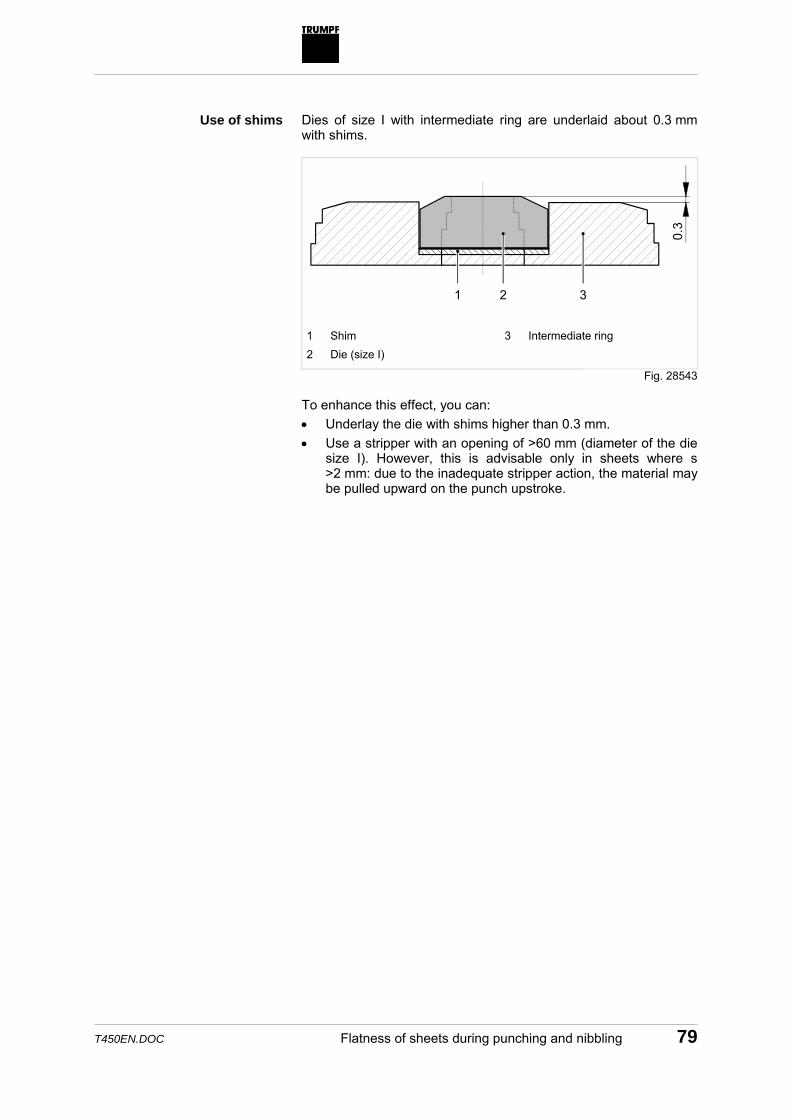
Dies of size I with intermediate ring are underlaid about 0.3 mm with shims.
0.3
1 2 3 1 Shim 2 Die (size I)
3 Intermediate ring
To enhance this effect, you can: • Underlay the die with shims higher than 0.3 mm. • Use a stripper with an opening of >60 mm (diameter of the die
size I). However, this is advisable only in sheets where s >2 mm: due to the inadequate stripper action, the material may be pulled upward on the punch upstroke.
Use of shims
Fig. 28543

80 Flatness of sheets during punching and nibbling T450EN.DOC
F
F
F
F
1
2
1 Stripper with opening <60 mm 2 Stripper with opening >60 mm F Presser foot force
Note For better illustration, the arching of stripper and sheet is exaggerated in the figure above.
In cases where the die cannot be underlaid with shims (e.g. for dies of size II), the die can be chamfered to a pyramid shape.
0.3
1
1 New bevels
Fig. 28544
Chamfering the die
Fig. 28545

T450EN.DOC Flatness of sheets during punching and nibbling 81
The die is ground off 0.3 mm with the aid of the tool grinding machine, the QuickSharp.
In this process, the die is shimmed in the grinding adapter on one side and ground down except for an area of 3–5 mm around the die opening; it is then turned 90° at a time and ground again in that position. The result is a die with four evenly beveled faces.
Chamfered die Pre- and post-punching
Sheet deformation can also be reduced by means of pre- and post-punching. In this method, just as in "strain-free machining", the area of strain in the sheet is punched off. However, it must be assured that only very little material will be removed by post-punching as new strains will otherwise appear in the sheet (i.e. the punches used for pre- and post-punching vary only minimally in diameter).
In testing, it was possible to reduce sheet deformation by half by pre-punching with a round punch diameter 9.8 mm and post-punching with a tool 10.0 mm in diameter.
Fig. 5450

82 Appendix T450EN.DOC
7. Appendix
7.1 Operation of the hydraulic punching head
A
B
8
1
2
3
4
57
6
9
10
A Upper ram surface B Lower ram surface 1 Punch 2 Ram 3 Pinion 4 Rack
5 Hydraulic valve 6 CNC control 7 Ram control 8 Stepping motor 9 To the tank 10 From the pump
Schematic structure The control system specifies the distance of the ram above the sheet surface. This distance is set via a stepping motor. In this start position, the lower ram surface is under hydraulic pressure before the punching stroke is executed.
Fig. 28546
Setting the ram position

T450EN.DOC Appendix 83
The punching stroke is started by another signal from the control system. The hydraulic valve for the linear amplifier is opened and feeds a flow of oil to the ram surface which makes the ram travel downwards. If the ram now touches the sheet, the hydraulic pressure on the upper ram surface is automatically increased until the sheet has been punched through. In addition, the hydraulic pressure on the lower ram surface is switched off when a very strong punching capacity requirement is needed. After punching through, the ram reaches its lowest position. The hydraulic valve is then closed via mechanical regeneration, through toothed rack and pinion gears. The ram is returned to the start position by increasing the hydraulic pressure on the lower ram surface while simultaneously sinking the pressure on the upper ram surface.
Executing the punching stroke
Return stroke of ram

84 Appendix T450EN.DOC
7.2 Tables of maximum capacities
The maximum permissible dimensions for round and square tools can, with and without shear, be referred to in the tables of maximum capacities for four tensile strengths and varying material thicknesses. For intermediate values of the material thickness and tensile strength, either the next lowest table value should be referred to or, otherwise, the tool dimension calculated according to the following formulas:
Rmsxpd⋅⋅⋅
⋅=
9.0max
π
dmax Maximum tool diameter (round) [mm] p Punching capacity [N] s Material thickness [mm] Rm Tensile strength [N/mm2] x Shearing factor (for tools without Shearing bevel = 1)
Rmsxpa⋅⋅⋅
⋅=
9.04max
amax Maximum edge length (square) [mm] p Punching capacity [N] s Material thickness [mm] Rm Tensile strength [N/mm2] x Shearing factor (for tools without Shearing bevel = 1)
RmspLMax⋅⋅
=9.0
Lmax Maximum cutting perimeter [mm] P Punching capacity [N] S Material thickness [mm] Rm Tensile strength [N/mm2]
maximum diameter for round tools
Maximum edge length for square tools
Maximum cutting perimeter for randomly shaped or cluster punching tools without shearing bevel

T450EN.DOC Appendix 85
7.3 Feed step
The feed step for nibbling must be separately selected according to the tool deployed. The feed step is adjusted according to the desired roughness depth. At the same time, you have to differentiate between round tools, square- and rectangular tools and slitting tools, oblong tools and tools with corner radius.
Nibble edge If a contour is nibbled using a round tool, the nibble edge shows a roughness (depth of roughness) which correlates with the selected feed step. When a smaller feed step is used, the quality of the nibble edge improves, i.e. the roughness will be less.
Depth of roughness
Fig. 28520

86 Appendix T450EN.DOC
Round tools The optimum feed step for round tools can be read in the following roughness-depth diagram.
Rt Roughness depth [mm] d Punch diameter [mm] Spp Feed step [mm/stroke]
a Rd coarse b Rd medium c Rt fine
Roughness-depth diagram The following rule-of-thumb formula applies for the minimum feed step:
s0.5Sppmin ⋅=
Sppmin Minimum feed step [mm/stroke] s Material thickness [mm] The rest is differentiated according to linear and circular feed step. The linear feed step follows a straight path, the circular feed step follows a circle.
Fig. 19497

T450EN.DOC Appendix 87
Spp Rt
D
Spp Feed step [mm] Rt Roughness depth [mm] D Tool diameter [mm]
The linear feed step can also be calculated according to the following equation:
( )RtDRtSpplinear −⋅⋅= 4
Spplinear Linear feed step [mm/stroke] D Tool diameter [mm] Rt Roughness depth [mm]
�
���
�
��
��
Spp Feed step [mm] Rt Roughness depth [mm] D Tool diameter [mm]
R1 Radius of the tool center point path [mm]
R2 Radius of the workpiece edge [mm]
Linear feed step
Fig. 28547
Circular feed step
Fig. 13198
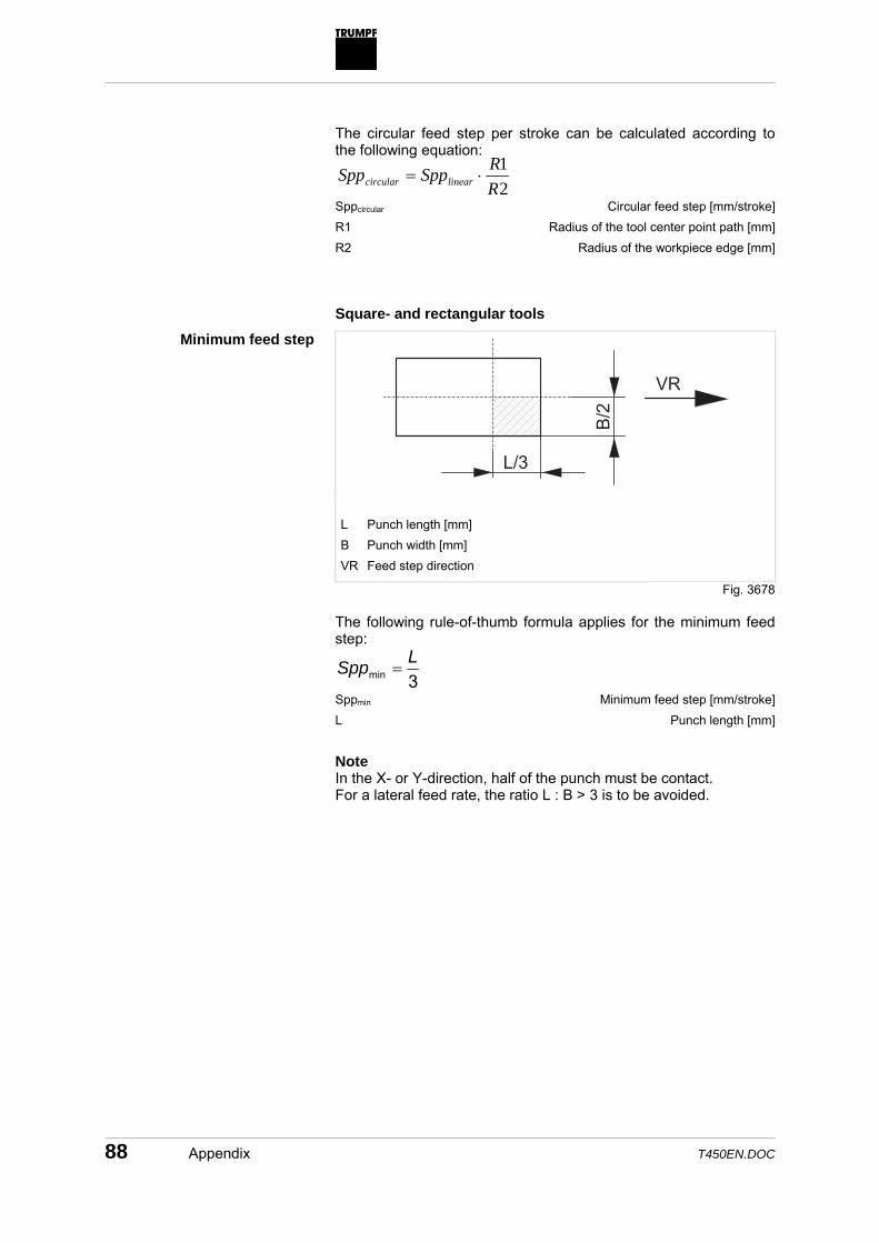
88 Appendix T450EN.DOC
The circular feed step per stroke can be calculated according to the following equation:
21
RRSppSpp linearcircular ⋅=
Sppcircular Circular feed step [mm/stroke] R1 Radius of the tool center point path [mm] R2 Radius of the workpiece edge [mm] Square- and rectangular tools
� �
���
� � �
L Punch length [mm] B Punch width [mm] VR Feed step direction
The following rule-of-thumb formula applies for the minimum feed step:
3minLSpp =
Sppmin Minimum feed step [mm/stroke] L Punch length [mm]
Note In the X- or Y-direction, half of the punch must be contact. For a lateral feed rate, the ratio L : B > 3 is to be avoided.
Minimum feed step
Fig. 3678

T450EN.DOC Appendix 89
� � � �
�
L Punch length [mm]
The following rule-of-thumb formula applies for the maximum feed step:
mmLSpp 2max −=
Sppmax Maximum feed step [mm/stroke] L Punch length [mm] Slitting tools, oblong tools, tools with corner radius The following rule-of-thumb formulas apply for the minimum and maximum feed step:
2minLSpp =
Sppmin Minimum feed step [mm/stroke] L Length of the punch [mm]
( ) mmRLSpp 12max −⋅−=
Sppmax Maximum feed step [mm/stroke] R Radius of the punch [mm]
Note The punch must always operate with the whole width. When cutting strips, the minimum width of the strip is 10 mm. If the minimum width is not reached, the deformation of the strip causes lateral forces to affect the punch, and thereby induce a reduction of its service life.
Maximum feed step
Fig. 0330
Minimum feed step
Maximum feed step

90 Appendix T450EN.DOC
7.4 Tensile strength
The most important materials with their tensile-strength range are listed below. If the actual tensile strength is not known, you can count on the maximum tensile strength of the tolerance range (column "Tensile strength Rm range". Abbreviation (DIN EN 10025)
Material number (DIN EN 10025)
Tensile strength Rm [N/mm2] range
St 33 1.0035 290-540 St 37-2 1.0037 340-510 St 37-3 1.0116 340-510 St 44-2 1.0044 410-580 St 44-3 1.0144 410-580 St 52-3 1.0570 510-680 St 50-2 1.0050 470-660 St 60-2 1.0060 570-770 St 70-2 1.0070 670-900
Abbreviation (DIN 17440)
Material number (DIN 17440)
Tensile strength Rm [N/mm2] range
X 7 Cr 13 1.4000 700 X 7 CrAl 13 1.4002 450-700 X 10 Cr 13 1.4006 550-750 X 15 Cr 13 1.4024 650-800 X 20 Cr 13 1.4021 650-950 X 40 Cr 13 1.4034 -800 X 45 CrMoV 15 1.4116 -900 X 8 Cr 17 1.4016 450-600 X 8 CrTi 17 1.4510 450-600 X 8 CrNb 17 1.4511 450-600 X 6 CrMo 17 1.4113 450-650 X 12 CrMoS 17 1.4104 550-850 X 22 CrNi 17 1.4057 850-950 X 12 CrNiS 18 8 1.4305 500-700 X 5 CrNi 18 9 1.4301 500-700 X 5 CrNi 19 11 1.4303 500-700 X 2 CrNi 18 9 1.4306 450-700 X 10 CrNiTi 18 9 1.4541 500-750 X 10 CrNiNb 18 9 1.4550 500-750 X 5 CrNiMo 18 10 1.4401 500-700 X 2 CrNiMo 18 10 1.4404 450-700 X 10 CrNiMoNb 1810 1.4580 500-750 X 5 CrNiMo 18 12 1.4436 500-700 X 2 CrNiMo 18 12 1.4435 450-700 X 2 CrNiMo 18 16 1.4438 500-700 X 2 CrNiN 18 10 1.4311 550-750
Mild steels
Tab. 16
Nonrusting- and acidproof steels
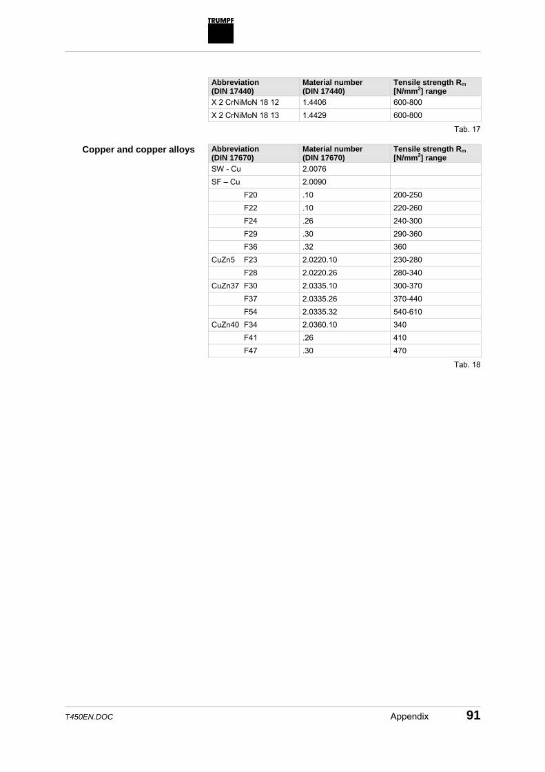
T450EN.DOC Appendix 91
Abbreviation (DIN 17440)
Material number (DIN 17440)
Tensile strength Rm [N/mm2] range
X 2 CrNiMoN 18 12 1.4406 600-800 X 2 CrNiMoN 18 13 1.4429 600-800
Abbreviation (DIN 17670)
Material number (DIN 17670)
Tensile strength Rm [N/mm2] range
SW - Cu 2.0076 SF – Cu 2.0090 F20 .10 200-250 F22 .10 220-260 F24 .26 240-300 F29 .30 290-360 F36 .32 360 CuZn5 F23 2.0220.10 230-280 F28 2.0220.26 280-340 CuZn37 F30 2.0335.10 300-370 F37 2.0335.26 370-440 F54 2.0335.32 540-610 CuZn40 F34 2.0360.10 340 F41 .26 410 F47 .30 470
Tab. 17
Copper and copper alloys
Tab. 18

92 Appendix T450EN.DOC
Abbreviation (DIN EN 485)
Material number (DIN EN 485)
Tensile strength Rm [N/mm2] range
Al 99.8 F10 3.0285 .26 100-140 Al 99.8 F12 3.0285 .30 120-160 Al 99.7 F10 3.0275 .26 100-140 Al 99.7 F12 3.0275 .30 120-160 Al 99.5 F8 3.0255 .07 75-110 F9 .24 90-130 F11 .26 110-150 F13 .30 130-170 F15 .32 150 AlMn1 F12 3.0515 .24 120-160 F14 .26 140-180 F17 .30 165-205 AlMnCu F13 3.0517 .24 125-165 F15 .26 145-185 F17 .28 170-210 AlMn1Mg1 F19 3.0526 .24 190-230 F22 .26 220-260 F26 .28 240-280 AlMg1 F13 3.3315 .24 125-165 F15 .26 145-185 F17 .28 165-205 AlMg3 F22 3.3535 .24 220-260 F24 .26 240-280 F27 .28 265-305 AlMgSi1 F21 3.2315 .51 205 F28 .71 275 F30 .72 295 AlCuMg1 F39 3.1325 .51 390 AlCuSiMn F40 3.1255 .51 400
Aluminum and aluminum alloys
Tab. 19

T450EN.DOC Appendix 93
Index
A Active presser foot ... 26, 33, 39, 42, 45, 61, 71,
72, 76, 78 Adhesive pad..............................52, 65, 69, 70 Alignment ring...................................30, 37, 50 Aluminum....................................31, 45, 77, 92 Arching over the sheet ............................77, 78
B Ball rollers.....................................................20 Ball rollers, liftable.........................................21 Bolt circle ........................................................9 Bowing of the sheet ......................................75 Brush ......................................................47, 69 Brush segment..............................................69 Brush tables............................................64, 70 Brushes ..................................................20, 71 Built-up edge ................................................45 Built-up edges...............................................73 Burr formation...................................71, 73, 76
C Cartridge type ...............................................26 Cartridge, see Tool cartridge ........................26 Chutes, fixed.................................................23 Clearance ................. 35, 40, 43, 59, 60, 72, 76 Cold welding .....................................31, 45, 73 Coordinate guide ..............................18, 19, 20 Copper....................................................77, 91 Cut out ............................................................8 Cut-out punching ..........................................23 Cutting clearance..........................................72
D Deformation of the sheet.........................74, 81 Depth of roughness ......................................85 Die ..............................................30, 40, 51, 70
Die with brush inserts............................. 40, 69 Drives..................................................... 19, 20
E Ejector.......................................................... 69 Electronic punching tool catalog............. 47, 54 Embossing ............................................. 13, 47 Evenness of the sheet.................................. 39 Execution ..................................................... 21
F Feed step............................................... 12, 85 Feed step, circular ....................................... 87 Feed step, linear .......................................... 87 Feed step, maximum ................................... 89 Feed step, minimum .................................... 88 Finish punching............................................ 72 Foil-coated sheets........................................ 73 Forming.......................9, 13, 26, 45, 46, 47, 69 Forming tool ..................................9, 26, 46, 69
G Gluing device ......................................... 52, 66
H Heat transmission ........................................ 45 Hit rate ................................................... 56, 58 Hole grids....................................................... 9 HSS super-speed steel .................... 12, 31, 37
I Insertion aid ................................................. 21 Intermediate ring with brush inserts ............. 69

94 Index T450EN.DOC
K Koordinatenführunge ....................................39
L Linear magazine .....................................21, 27 • tool ...................................................21, 30 • workpiece clamps.................18, 19, 21, 25 Linearmagazin ..............................................18 • Spannpratzen.........................................39 • Werkzeug ...............................................18 Loading the machine ....................................21 Long punch...................................................33 Loudness ......................................................57 Lubrication ............................35, 45, 46, 60, 73
M Magnetic plate ..............................................34 Marking...................................................13, 47 Material class..........................................56, 59 Material thickness . 9, 12, 35, 42, 54, 56, 60, 86 Microscopic burrs..........................................64 Mild steel ..........................................37, 59, 62 Multitool ........................................9, 25, 47, 69
N Nachsetzen...................................................39 Needle punch ...............................................31 Nibbling..................... 11, 37, 42, 45, 57, 62, 85 Nibbling punch..............................................42 Nibbling tool..................................................12 Noise level ....................................................57 Noise reduction............... 32, 46, 56, 57, 59, 60
O Outer circle diameter ..........................9, 25, 42
P Paper punching tool catalog......................... 54 Part removal ................................................ 23 Parts flap...................................................... 23 Passive presser foot ........................ 33, 39, 71 Path - time diagram...................................... 58 Peel off......................................................... 22 Perforating ..................................................... 8 Polyamide-coated strippers.......................... 71 Post-punching.............................................. 81 Pre-punching.......................................... 72, 81 Presser foot ..........................39, 59, 76, 77, 78 Press-set...................................................... 52 Processing • processing, row-by-row.......................... 72 Punch....................................11, 30, 31, 33, 51 Punch dimensions, maximum .......... 34, 42, 84 Punch dimensions, minimum ....................... 42 Punch marking ............................................. 13 Punching...............8, 10, 15, 42, 47, 56, 62, 74 Punching capacity.......9, 37, 40, 46, 54, 75, 83 Punching force stage ................................... 16 Punching slug ................................................ 8 Punching slugs......................40, 43, 65, 68, 74 Punching tool, see Tool................................ 12 Push out, row-by-row ................................... 23 Push-out stripper.......................................... 39
R Ram ..........................12, 17, 20, 45, 56, 82, 83 Ram position.......................................... 45, 82 Ram surface .......................................... 82, 83 Regrind length.................................... 9, 34, 49 Regrinding ....................................... 33, 46, 48 Relative position........................................... 37 Repositioning ................................... 22, 25, 26 Repositioning cylinder .................................. 26 Roller ........................................................... 70 Rollers.................................................... 64, 73 Rotary axis................................................... 17 Roughness............................................. 45, 85 Roughness tolerance ................................... 12 Roughness-depth diagram........................... 86 Row of holes .................................................. 9 RTC cartridge......................................... 26, 30
S Scratch-free machining .......................... 40, 47

T450EN.DOC Index 95
Service life ..............................................46, 89 Shape punch ................................................37 Shear factor ..................................................35 Shearing .........................................................8 Shearing bevel............ 9, 33, 34, 48, 59, 68, 84 Shearing factor .............................................84 Shearing-breakage ratio .........................43, 44 Sheet deformation ......................13, 43, 71, 72 Sheet quality.................................................21 Sheet weight .............................................9, 26 Shims......................................................41, 79 Size group ....................................................30 Slitting.........................................42, 46, 47, 62 Slitting tool ..................................66, 69, 76, 89 Slug retaining die ........................40, 68, 70, 71 Softpunch .....................................................56 Softpunch stage......................................56, 61 Solid punch...................................................31 Special tool ...................................................47 Stainless steel................. 31, 37, 45, 59, 62, 75 Stepping motor .............................................82 Stock list .......................................................55 Strain-free machining..............................76, 81 Stripper .. 17, 30, 39, 45, 51, 52, 65, 66, 70, 77,
78, 79 Stroke rate ..............................9, 12, 16, 56, 61
T Table of maximum capacities .................34, 36 Table of maximum capacity ..........................84 Table of stroke rates .......................................9 Technical information....................................47 Tensile strength .............. 31, 34, 36, 42, 84, 90 TICN-coating ..........................................12, 31
Tool.. 12, 17, 21, 26, 27, 30, 42, 46, 48, 54, 76, 84
Tool adapter................................21, 25, 30, 71 Tool cartridge..................21, 26, 30, 34, 37, 51 Tool infos ..................................................... 47 Tool length ....................................... 34, 39, 50 Tool life ........................................................ 12 Tool set .................................................. 18, 30 Tool setup list............................................... 27 Tool storage................................................. 27 Tool type ...................................................... 59 Tools ............................................................ 42 Trim.............................................................. 22 GripMaster 5000 .......................................... 29 SheetMaster 1305/1605............................... 29 SortMaster Pallet ......................................... 29 SortMaster Box ............................................ 29 StoreMaster ................................................. 29
V Variable forming height ................................ 22
W Whispertool, also see Shearing bevel ... 32, 33,
46, 59, 62, 68 Whispertool, also seeShearing bevel ........... 76 Whispertool, see also Shearing bevel .......... 59 Working height ........................9, 58, 67, 70, 71 Workpiece clamps.......................18, 19, 21, 25

96 Index T450EN.DOC