licensing notice - unsolicited correspondence - 2 for ... · appendix 3 design calculations ... the...
TRANSCRIPT

Licensing Notice - Unsolicited Correspondence - 2 for CastlecomerLicence (D0149-01)
Licence: Castlecomer (D0149-01)
Action Type: Licensing Notice
Castlecomer WWTW Preliminary Report
Issued On: 16/10/2013
ClosedStatus Reason:
Unsolicited CorrespondenceStatus History Action:
For
insp
ectio
n pur
pose
s only
.
Conse
nt of
copy
right
owne
r req
uired
for a
ny ot
her u
se.
EPA Export 16-10-2013:23:47:18

Comhairle Contae Chill Chainnigh Kilkenny County Council
Castlecomer Wastewater Treatment Plant Upgrade
Preliminary Outline Design Report
February 2012 Rev C
TOBIN CONSULTING ENGINEERS
For
insp
ectio
n pur
pose
s only
.
Conse
nt of
copy
right
owne
r req
uired
for a
ny ot
her u
se.
EPA Export 16-10-2013:23:47:18
Template rep 003
REPORT
PROJECT: Castlecomer Wastewater Treatment Plant Upgrade
CLIENT: Kilkenny County Council County Hall John Street Kilkenny
COMPANY: TOBIN Consulting Engineers Fairgreen House Fairgreen Road Galway Tel: 091-565211 Fax: 091-565398 Email: [email protected]
www.tobin.ie
For
insp
ectio
n pur
pose
s only
.
Conse
nt of
copy
right
owne
r req
uired
for a
ny ot
her u
se.
EPA Export 16-10-2013:23:47:18
Castlecomer WWTP Upgrade
i
DOCUMENT AMENDMENT RECORD
Client: Kilkenny County Council Project: Castlecomer Wastewater Treatment Plant Upgrade Title: Preliminary Outline Design Report
PROJECT NUMBER: 6676 DOCUMENT REF: Castlecomer WWTP Preliminary Report RevB
C Client comments
amendments PMF Feb-12 BJD Feb-12 BJD Feb-12
B Updated to Include Part 8 Planning Drawings
PMF Jan-12 BJD Jan-12 BJD Jan-12
A Issue to Client PMF Nov-11 BJD Dec 11 BJD Nov 11
Revision Description & Rationale Originated Date Checked Date Authorised Date TOBIN Consulting Engineers
For
insp
ectio
n pur
pose
s only
.
Conse
nt of
copy
right
owne
r req
uired
for a
ny ot
her u
se.
EPA Export 16-10-2013:23:47:18

Castlecomer WWTP Upgrade
ii
TABLE OF CONTENTS
1 INTRODUCTION ........................................................................................................................ 1
1.1 BACKGROUND .................................................................................................................. 1
1.2 SCOPE OF WORK.............................................................................................................. 1
1.3 METHODOLOGY ................................................................................................................ 1
1.4 SUMMARY OF PROPOSED UPGRADE OPTION ............................................................. 1
2 EXISTING WASTEWATER TREATMENT PLANT ................................................................... 2
2.1 SEWER NETWORK AND SIPHONS .................................................................................. 2
2.2 INLET WORKS ................................................................................................................... 2
2.3 IMHOFF TANK .................................................................................................................... 3
2.4 PERCOLATING FILTERS ................................................................................................... 4
2.5 CLARIFIER ......................................................................................................................... 4
2.6 WASTE SLUDGE PUMP SUMP ......................................................................................... 5
2.7 SLUDGE DRYING BEDS .................................................................................................... 5
2.8 ADMINISTRATION BUILDINGS ......................................................................................... 5
3 DESIGN LOADING AND FINAL EFFLUENT STANDARDS .................................................... 6
3.1 DESIGN LOAD .................................................................................................................... 6
3.2 INTRODUCTION ................................................................................................................. 6
4 PROPOSED UPGRADE OF SIPHON AND TREATMENT WORKS ........................................ 8
4.1 INTRODUCTION ................................................................................................................. 8
4.2 UPGRADE OF SIPHON ...................................................................................................... 9
4.3 INLET WORKS ................................................................................................................. 10
4.4 UTILISE EXISTING IMHOFF TANK AS BUFFER TANK .................................................. 10
4.5 SEQUENTIAL BATCH REACTORS ................................................................................. 11
4.6 PHOSPHOROUS REMOVAL ........................................................................................... 11
4.7 TERTIARY TREATMENT (PERCOLATING FILTERS AND FLOW SPLITTER) .............. 12
4.8 PICKET FENCE THICKENER (MODIFY EXISTING CLARIFIER) ................................... 12
4.9 SLUDGE HOLDING TANK................................................................................................ 12
4.10 ADMINISTRATON BUILDINGS ..................................................................................... 13
4.11 MEASUREMENT AND SAMPLING ............................................................................... 13
4.12 PHASING OF CONSTRUCTION ................................................................................... 13
4.13 ENVIRONMENTAL IMPACT ......................................................................................... 14
For
insp
ectio
n pur
pose
s only
.
Conse
nt of
copy
right
owne
r req
uired
for a
ny ot
her u
se.
EPA Export 16-10-2013:23:47:18

Castlecomer WWTP Upgrade
iii
4.14 OPERATIONAL MANAGEMENT................................................................................... 14
5 COST ESTIMATES .................................................................................................................. 15
5.1 CAPITAL COSTS .............................................................................................................. 15
5.2 OPERATION AND MAINTENANCE COSTS .................................................................... 15
6 STATUTORY REGULATIONS ................................................................................................ 16
6.1 ENVIRONMENTAL CONSTRAINTS AND EIS ................................................................. 16
6.2 WASTE WATER DISCHARGE APPLICATION ................................................................ 16
6.3 PART 8 PLANNING PERMISSION ................................................................................... 16
6.4 LAND ACQUISITION / WAYLEAVES ............................................................................... 16
7 SUMMARY AND RECOMMENDATIONS ............................................................................... 17
APPENDICES Appendix 1 Drawings
Appendix 2 Cost Estimate
Appendix 3 Design Calculations
Appendix 4 Effluent Quality Results
For
insp
ectio
n pur
pose
s only
.
Conse
nt of
copy
right
owne
r req
uired
for a
ny ot
her u
se.
EPA Export 16-10-2013:23:47:18
Castlecomer WWTP Upgrade
1
1 INTRODUCTION 1.1 BACKGROUND Castlecomer is located on the N78 National Secondary Route approximately 19 kilometres north of Kilkenny city. The wastewater treatment plant serving the town was originally constructed for a design capacity of 1,300p.e. and consisted of a percolating filter plant with stone as the filter media. The plant was upgraded in 2000 to a design capacity of 2,500p.e. This upgrade included the replacement of the existing stone media in the percolating filters with Marpak plastic media. It also included the construction of a clarifier for clarification of the effluent from the percolating filters. In September 2008 Kilkenny County Council applied to the EPA for a Waste Water Discharge License for the agglomeration of Castlecomer (Registration No. D0149-01). The application is still under assessment by the EPA. Kilkenny County Council have anticipated the increased treatment capacity which will be required in order to improve current effluent quality to comply with expected emission limit values arising from EPA licensing. Kilkenny County Council now proposes to upgrade the existing treatment capacity at Castlecomer WWTP in anticipation of these impending emission limit values.
1.2 SCOPE OF WORK The purpose of this Preliminary Outline Design Report is to assess, in accordance with the agreed brief from Kilkenny County Council, the existing wastewater treatment plant and to evaluate the options available to upgrade the plant so as to achieve the required effluent quality standards. The scope of works includes the following:
• Review the existing wastewater treatment process. • Conduct a site inspection. • Identify what elements of the existing plant can be usefully retained and what elements
need to be abandoned or replaced. • Prepare an outline design for the upgraded plant, including selection of an appropriate
treatment process. • Estimate initial capital and operational cost. • Advise on statutory procedures that will need to be carried out to implement the proposed
designs. 1.3 METHODOLOGY Site visits to the existing wastewater treatment plant in Castlecomer were carried out in order to evaluate the existing plant and evaluate the works required to upgrade the plant. Taking into account the restricted footprint of the site and the configuration of the existing plant, a Sequence Batch Reactor (SBR) treatment plant option was selected, designed and priced as detailed in Appendices 2 and 3. 1.4 SUMMARY OF PROPOSED UPGRADE OPTION The key recommendations arising from the preliminary outline design process are as follows:
• Upgrade the existing Siphon arrangement crossing the River Deen • Construct new Inlet Works • Modify the existing Imhoff Tank to operate as a Buffer Tank • Construct 2 No. new Sequential Batch Reactors • Provide for dosing of sewage with ferric sulphate to provide backup for biological nutrient
removal • Modify existing clarifier to operate as Picket Fence Thickener • Construct new Sludge Holding Tank
Layout and elevation drawings for the existing and proposed works within the Castlecomer WWTP site are provided in Appendix 1.
For
insp
ectio
n pur
pose
s only
.
Conse
nt of
copy
right
owne
r req
uired
for a
ny ot
her u
se.
EPA Export 16-10-2013:23:47:18
Castlecomer WWTP Upgrade
2
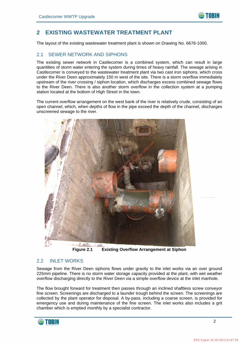
2 EXISTING WASTEWATER TREATMENT PLANT The layout of the existing wastewater treatment plant is shown on Drawing No. 6676-1000. 2.1 SEWER NETWORK AND SIPHONS The existing sewer network in Castlecomer is a combined system, which can result in large quantities of storm water entering the system during times of heavy rainfall. The sewage arising in Castlecomer is conveyed to the wastewater treatment plant via two cast iron siphons, which cross under the River Deen approximately 150 m west of the site. There is a storm overflow immediately upstream of the river crossing / siphon location, which discharges excess combined sewage flows to the River Deen. There is also another storm overflow in the collection system at a pumping station located at the bottom of High Street in the town. The current overflow arrangement on the west bank of the river is relatively crude, consisting of an open channel, which, when depths of flow in the pipe exceed the depth of the channel, discharges unscreened sewage to the river.
Figure 2.1 Existing Overflow Arrangement at Siphon
2.2 INLET WORKS Sewage from the River Deen siphons flows under gravity to the inlet works via an over ground 225mm pipeline. There is no storm water storage capacity provided at the plant, with wet weather overflow discharging directly to the River Deen via a simple overflow device at the inlet manhole. The flow brought forward for treatment then passes through an inclined shaftless screw conveyor fine screen. Screenings are discharged to a launder trough behind the screen. The screenings are collected by the plant operator for disposal. A by-pass, including a coarse screen, is provided for emergency use and during maintenance of the fine screen. The inlet works also includes a grit chamber which is emptied monthly by a specialist contractor.
For
insp
ectio
n pur
pose
s only
.
Conse
nt of
copy
right
owne
r req
uired
for a
ny ot
her u
se.
EPA Export 16-10-2013:23:47:18

Castlecomer WWTP Upgrade
3
Figure 2.2 Existing Inlet Screen
2.3 IMHOFF TANK The flow from the inlet works enters an Imhoff Tank, where primary sedimentation is achieved within a horizontal flow settlement tank (upper chamber). The settled solids are then degraded under anaerobic digestion within the lower chamber of the tank. Sludge is wasted manually by the site caretaker to the sludge drying beds every 5 days by opening a de-sludge valve. The dimensions of the existing Imhoff Tank are 13.71m long x 4.88m wide x 4.8m deep, with a capacity of 321m³. Effluent from the Imhoff Tank flows through a flow measurement device. This device records the incoming flows to the WWTP downstream of the storm overflow which is located upstream of the
For
insp
ectio
n pur
pose
s only
.
Conse
nt of
copy
right
owne
r req
uired
for a
ny ot
her u
se.
EPA Export 16-10-2013:23:47:18

Castlecomer WWTP Upgrade
4
existing inlet works. Flows are recorded by an ultrasonic measuring device, which transmits the data to a digital display within the electrical control panel in the administration building. 2.4 PERCOLATING FILTERS Effluent from the Imhoff Tank flows to a siphon tank where it is split into two streams, each stream being fed to one of two trickling filters. Each filter has an internal diameter of 14m (308m2 surface area) and a depth of 1.5m. The filter media used is Marpak plastic, installed as part of the 2000 plant upgrade.
Figure 2.3 Existing Percolating Filters
The wastewater is distributed onto the surface of the filters by rotating arms and percolates downwards, causing a layer of biofilm to grow on the surface of the media. Aerobic conditions are maintained by splashing, diffusion and natural convection. This layer of microbial biofilm removes organic compounds through absorption and adsorption before being sloughed off as the biofilm layer thickens. 2.5 CLARIFIER The effluent from the Percolating Filters is pumped via two forward feed pumps to a Clarifier, which has an internal diameter of 10m and is 2.5m deep. Sludge settlement takes place within this tank. A rotating half bridge scraper directs the sludge towards a central hopper, from where it is wasted to the sludge drying beds weekly. Sludge is wasted manually by the site caretaker to the sludge drying beds by opening a de-sludge valve. The existing Clarifier was constructed in 2000 as part of the upgrade of the treatment works to a treatment capacity of 2,500p.e.
For
insp
ectio
n pur
pose
s only
.
Conse
nt of
copy
right
owne
r req
uired
for a
ny ot
her u
se.
EPA Export 16-10-2013:23:47:18
Castlecomer WWTP Upgrade
5
2.6 WASTE SLUDGE PUMP SUMP An underground Waste Activated Sludge (WAS) pump sump is located adjacent to the Imhoff Tank to provide sludge draw off from the Imhoff Tank and sludge draw off and scum collection from the Clarifier. The sludge is wasted to the sludge drying beds. 2.7 SLUDGE DRYING BEDS At present, waste sludge from the treatment process is pumped onto sludge drying beds. There are five beds in all with an overall capacity, including the sand, gravel and stone media, of 268m3. Currently the plant operator utilises two of the five beds, with an overall volume of 107m³ and an effective sludge storage volume of 20m³. A specialist contractor arrives on site monthly to remove the sludge from the sludge drying beds. 2.8 ADMINISTRATION BUILDINGS The existing administration building is a single storey pre-fab and includes the following accommodation:
• Office • Welfare facilities
A single-storey control building is also located on site within which the instrumentation and flow meters are located.
For
insp
ectio
n pur
pose
s only
.
Conse
nt of
copy
right
owne
r req
uired
for a
ny ot
her u
se.
EPA Export 16-10-2013:23:47:18
Castlecomer WWTP Upgrade
6
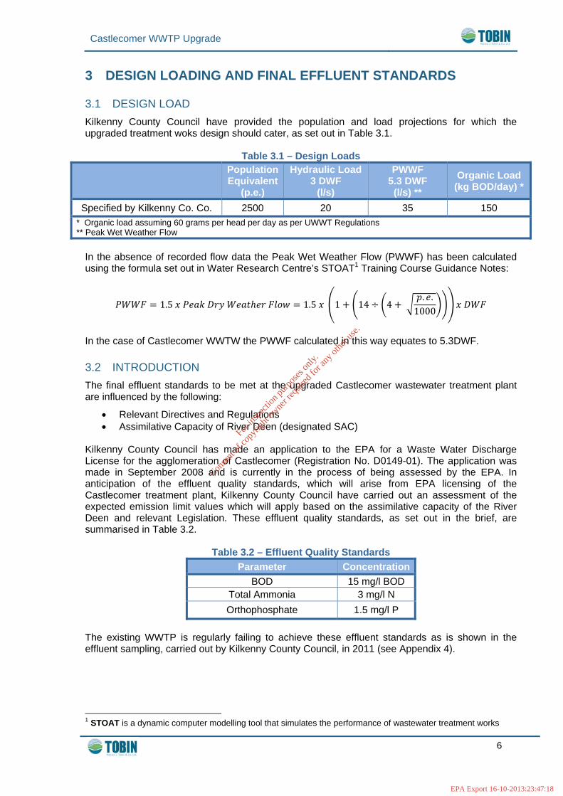
3 DESIGN LOADING AND FINAL EFFLUENT STANDARDS 3.1 DESIGN LOAD Kilkenny County Council have provided the population and load projections for which the upgraded treatment woks design should cater, as set out in Table 3.1.
Table 3.1 – Design Loads
Population Equivalent
(p.e.)
Hydraulic Load 3 DWF
(l/s)
PWWF 5.3 DWF (l/s) **
Organic Load (kg BOD/day) *
Specified by Kilkenny Co. Co. 2500 20 35 150 * Organic load assuming 60 grams per head per day as per UWWT Regulations ** Peak Wet Weather Flow
In the absence of recorded flow data the Peak Wet Weather Flow (PWWF) has been calculated using the formula set out in Water Research Centre’s STOAT1 Training Course Guidance Notes:
1.5 1.5 1 14 4 . .
1000
In the case of Castlecomer WWTW the PWWF calculated in this way equates to 5.3DWF. 3.2 INTRODUCTION The final effluent standards to be met at the upgraded Castlecomer wastewater treatment plant are influenced by the following:
• Relevant Directives and Regulations • Assimilative Capacity of River Deen (designated SAC)
Kilkenny County Council has made an application to the EPA for a Waste Water Discharge License for the agglomeration of Castlecomer (Registration No. D0149-01). The application was made in September 2008 and is currently in the process of being assessed by the EPA. In anticipation of the effluent quality standards, which will arise from EPA licensing of the Castlecomer treatment plant, Kilkenny County Council have carried out an assessment of the expected emission limit values which will apply based on the assimilative capacity of the River Deen and relevant Legislation. These effluent quality standards, as set out in the brief, are summarised in Table 3.2.
Table 3.2 – Effluent Quality Standards Parameter Concentration
BOD 15 mg/l BOD Total Ammonia 3 mg/l N Orthophosphate 1.5 mg/l P
The existing WWTP is regularly failing to achieve these effluent standards as is shown in the effluent sampling, carried out by Kilkenny County Council, in 2011 (see Appendix 4).
1 STOAT is a dynamic computer modelling tool that simulates the performance of wastewater treatment works
For
insp
ectio
n pur
pose
s only
.
Conse
nt of
copy
right
owne
r req
uired
for a
ny ot
her u
se.
EPA Export 16-10-2013:23:47:18

Castlecomer WWTP Upgrade
7
In addition to the effluent standards outlined in Table 3.2, an effluent Nitrate level of 10mg/l is also assumed. This limit is required for the purpose of quantifying the anoxic cycle time and recirculation rate, and was assumed with respect to the effluent standard requirements stipulated for wastewater treatment plants discharging to sensitive waters, as cited in the Urban Waste Water Treatment Regulations (2001). All effluent limit standards used for the purpose of this preliminary design will need to be verified by the EPA licensing prior to progressing with the detailed design stage.
For
insp
ectio
n pur
pose
s only
.
Conse
nt of
copy
right
owne
r req
uired
for a
ny ot
her u
se.
EPA Export 16-10-2013:23:47:18
Castlecomer WWTP Upgrade
8
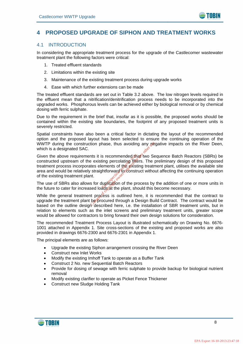
4 PROPOSED UPGRADE OF SIPHON AND TREATMENT WORKS 4.1 INTRODUCTION In considering the appropriate treatment process for the upgrade of the Castlecomer wastewater treatment plant the following factors were critical:
1. Treated effluent standards
2. Limitations within the existing site
3. Maintenance of the existing treatment process during upgrade works
4. Ease with which further extensions can be made
The treated effluent standards are set out in Table 3.2 above. The low nitrogen levels required in the effluent mean that a nitrification/denitrification process needs to be incorporated into the upgraded works. Phosphorous levels can be achieved either by biological removal or by chemical dosing with ferric sulphate.
Due to the requirement in the brief that, insofar as it is possible, the proposed works should be contained within the existing site boundaries, the footprint of any proposed treatment units is severely restricted.
Spatial constraints have also been a critical factor in dictating the layout of the recommended option and the proposed layout has been selected to ensure the continuing operation of the WWTP during the construction phase, thus avoiding any negative impacts on the River Deen, which is a designated SAC.
Given the above requirements it is recommended that two Sequence Batch Reactors (SBRs) be constructed upstream of the existing percolating filters. The preliminary design of this proposed treatment process incorporates elements of the existing treatment plant, utilises the available site area and would be relatively straightforward to construct without affecting the continuing operation of the existing treatment plant.
The use of SBRs also allows for duplication of the process by the addition of one or more units in the future to cater for increased loads at the plant, should this become necessary.
While the general treatment process is outlined here, it is recommended that the contract to upgrade the treatment plant be procured through a Design Build Contract. The contract would be based on the outline design described here, i.e. the installation of SBR treatment units, but in relation to elements such as the inlet screens and preliminary treatment units, greater scope would be allowed for contractors to bring forward their own design solutions for consideration.
The recommended Treatment Process Layout is illustrated schematically on Drawing No. 6676-1001 attached in Appendix 1. Site cross-sections of the existing and proposed works are also provided in drawings 6676-2300 and 6676-2301 in Appendix 1.
The principal elements are as follows:
• Upgrade the existing Siphon arrangement crossing the River Deen • Construct new Inlet Works • Modify the existing Imhoff Tank to operate as a Buffer Tank • Construct 2 No. new Sequential Batch Reactors • Provide for dosing of sewage with ferric sulphate to provide backup for biological nutrient
removal • Modify existing clarifier to operate as Picket Fence Thickener • Construct new Sludge Holding Tank
For
insp
ectio
n pur
pose
s only
.
Conse
nt of
copy
right
owne
r req
uired
for a
ny ot
her u
se.
EPA Export 16-10-2013:23:47:18

Castlecomer WWTP Upgrade
9
4.2 UPGRADE OF SIPHON At present the maximum flow to the inlet works at Castlecomer is limited by the capacity of the two cast iron siphons (150mm dia. and 100mm dia.) crossing the River Deen. It is recommended that before any detailed design is carried out on the proposals contained within this report that a comprehensive survey of incoming flow be carried out to determine:
(a) the response of the collection system to rainfall (b) the upper limit of hydraulic load for which the proposed new inlet works will have to cater
Flow logging devices should be placed in suitable manholes upstream of the siphon, (as close to the siphon as possible) and downstream, as close to the treatment plant inlet as possible. Currently wastewater is brought to the upstream siphon manhole via a 375mm diameter gravity sewer. Consideration was given to removing entirely the siphon crossing and replacing it with a continuous 375mm diameter gravity flow pipeline between the N78 and the WWTP. This arrangement would have required a high level river crossing, either supported on the existing bridge or on a new structure over the River Deen. Approximately 200m of pipeline would have to be laid, about 140m of that being above ground. The advantage of the proposed arrangement is that all flows would be brought to the proposed inlet works and receive at least preliminary treatment prior to being discharged to the River Deen. However the proposal was discounted for the following reasons:
1. The difference in ground levels between the west and east banks of the river means that the downstream invert level of a gravity sewer crossing the river would need to be above the soffit level of the existing bridge, and would therefore be significantly higher than existing ground level on the east bank.
2. Supporting a gravity sewer on the existing stone arch bridge would be visually intrusive and undesirable; the cost of constructing an independent support structure for the sewer would be prohibitive when compared with the cost of upgrading the existing overflow.
It is therefore proposed to upgrade the overflow arrangements on the upstream side of the siphon, to allow a maximum of 3 DWF to pass from the siphon to the treatment works. This will involve the installation of a hydrodynamic vortex separator, such as the StormKing® overflow, or similar approved vortex overflow, and a flow control device, such as a Hydrobrake® or similar approved flow control equipment. At present flows decanted into the river from the overflow are unscreened. The design of the flow control and vortex overflow devices should:
(a) set the maximum flow allowed to pass to the treatment plant (b) provide the equivalent of 6mm bar screening to excess flows discharged to the river
In order to allow proper sizing of the flow control and overflow installations a flow survey will be carried out, measuring dry weather flows and peak flows generated in the collection system during rainfall events. For the purposes of this report we have assumed the design DWF, as given in the client’s brief, and a peak wet weather flow of 35 l/s, calculated on the WRc formula. (Therefore 20 l/s of the PWWF will be passed on to the plant for treatment, with flows in excess of this decanted into the River Deen, via the vortex overflow.) We have also assumed, for the purposes of estimating costs, that a StormKing® and Hydrobrake® will be installed to create the storm water overflow. The StormKing® would be installed in newly constructed manhole off the line of the existing 375mm diameter sewer. This means that new wayleaves will be required to accommodate the proposed overflow arrangements.
For
insp
ectio
n pur
pose
s only
.
Conse
nt of
copy
right
owne
r req
uired
for a
ny ot
her u
se.
EPA Export 16-10-2013:23:47:18

Castlecomer WWTP Upgrade
10
4.3 INLET WORKS Based on the available flow data taken by Kilkenny County Council between February and July 2011 the maximum flow to treatment measured downstream of the Imhoff Tank over this period was recorded as 602m³/d. The projected average DWF, as specified by Kilkenny County Council, is 6.7 l/s (575m3/day). In order to achieve a cost effective solution it is recommended that a full flow to treatment of 3 DWF (20 l/s) be brought forward from the new storm overflow arrangement described in Section 4.2. The existing inlet screens are not performing well and have created maintenance problems in the past. For the purposes of this report it is taken that the existing screens will be replaced with a vertical band screen. The proposed inlet screens will cater for flows up to 3 DWF (20l/s). The new inlet works will also be required to have the capacity to accommodate additional screens in parallel to that now proposed, in order to cater for a potential future capacity. For the purposes of this report, these parallel preliminary treatment units will be sized to cater for a further 3DWF. In the event of such flows having to be catered for in the future, adjustments would also be required at the vortex overflow, to increase the flow brought forward for treatment to 40 l/s. However this, along with the DWF itself, will be confirmed by a full flow survey prior to detailed design. The vortex or other overflow device at the siphon crossing should ensure that more than 90% of grit in the combined flows will be retained in the flow sent forward for treatment. The upgraded inlet works should therefore incorporate grit removal equipment. As with the proposed screening equipment a grit trap capable of handling estimated future peak wet weather flows has been included in the cost estimates for the proposed upgrade works. Screenings and grit removed from the treatment process flow will be held in separate covered containers for disposal off site as occurs at present. It is proposed to pump treated effluent from the upgraded works back to the inlet works to wash down the screens and other equipment. This can be done using the existing pumps and pipe work which currently delivers effluent from the percolating filters to the clarifier. While an outline design has been prepared for this Report in order to estimate costs of the proposed works, it is recommended that a Design / Build approach be taken to the procurement of the inlet works. Tendering contractors will be given the data collected in the proposed flow survey of peak and dry weather flows and will be required to bring forward their design proposals with their tenders. 4.4 UTILISE EXISTING IMHOFF TANK AS BUFFER TANK The proposed upgraded works are designed to accommodate a full flow to treatment of 3 DWF. Given the physical constraints on the site, the proposed treatment process is an activated sludge process, to be carried out in Sequence Batch Reactors (SBRs). A buffer tank will be required downstream of the new inlet works to allow sewage to be held for pumping on the SBRs at specific intervals. The proposed SBR design for the Castlecomer treatment plant operates on a cycle time of four hours. Pumping from the buffer tank to the SBRs will occur during the anoxic period (18 minutes) at the start of each cycle, as described in Section 4.6 below. Each SBR’s operational cycle will be staggered by two hours, therefore resulting in a two hour interval between the start of each fill phase. The required Buffer Tank capacity has been calculated to provide two hours retention time at 3 DWF, which equates to a required tank volume of 144m³. This is adequately provided for by the existing Imhoff Tank (321m³) without the requirement for any additional buffering capacity. The conversion of the Imhoff tank to a buffer tank will require some modification of the existing tank including the installation of a mixer and the construction of an external, forward feed pump sump from which sewage will be delivered to the SBRs.
For
insp
ectio
n pur
pose
s only
.
Conse
nt of
copy
right
owne
r req
uired
for a
ny ot
her u
se.
EPA Export 16-10-2013:23:47:18

Castlecomer WWTP Upgrade
11
The piping and instrumentation for the SBRs will be arranged to facilitate pumping to one or other of the SBRs from the buffer tank pump sump. The potential to construct a new buffer tank and use the existing Imhoff Tank as a Storm Water Attenuation Tank was considered but was deemed unnecessary as the inflow to the WWTP will be limited at 3 DWF due to the overflow arrangement at the siphons, thus negating any requirement for storm water capacity within the site. 4.5 SEQUENTIAL BATCH REACTORS The upgraded WWTP is required to treat sewage loads from 2,500p.e. to the effluent standards set out in Table 3.2. Details of the SBR design are included in the design calculations provided in Appendix 3 of this Report. The tanks are sized to allow the nitrification / denitrification process to take place and reduce nitrogen levels in the final effluent to the required levels. For the effluent quality standards to be achieved it is critical that the hydraulic retention time (HRT) in the SBR tank is above 13.95 hrs for the peak design flow of 3 DWF. The process has been designed for this HRT and the effluent concentrations are expected to achieve a higher effluent quality than the standards set by Kilkenny County Council. The recommended upgrade will provide two SBR tanks of 502m³ each (10.8m dia. x 5.5m high), to include an initial volume, V0, of 359m³ and a fill volume, VF, of 144m³. These SBRs will operate on a cycle time as outlined in Table 4.1, with the start of each SBR’s cycle time staggered by two hours, i.e. Tc / 2. The overall cycle includes a designated anoxic period, to allow denitrification to occur and the required nitrogen levels in the treated effluent to be achieved. Filling of the SBRs will occur during the anoxic period at a rate sufficient to feed the denitrification process, but not so high as to cause aeration in the tank.
Table 4.1 – SBR Cycle Time Tc Total Cycle TAOX Anoxic (Fill) TA Aerobic
TS+D+I Settle, Draw and Idle
The location of the two SBRs, and the resulting sewage and sludge pipe work and pumping, is shown on Drawing No. 6676-1002 in Appendix 1. Elevations of the proposed SBR’s are provided in drawings 6676-2300 to 6676-2301 in Appendix 1. A typical SBR cross-section is also provided in drawing 6676-2302. The tanks would also require the installation of mechanical and electrical equipment to include a diffused air distribution system on the floor of the tank. 4.6 PHOSPHOROUS REMOVAL At the detailed design and tender stage tendering contractors will be required to set out how they will achieve the necessary phosphorous level in the treated effluent. It may be possible to achieve some or all of the Phosphorous removal biologically in the SBRs themselves. However it would be prudent to provide chemical dosing facilities to ensure that the required Phosphorous levels in the treated effluent can be achieved consistently. For the purposes of this report we have included for the provision of such chemical dosing systems. It is proposed to use ferric sulphate dosing to reduce the phosphorous levels. Ferric dosing of approximately 12.3kg Fe/day will be required to achieve the effluent quality standards stated in the Client’s Brief. The dosing pumps, day tanks and other equipment will be housed in a small extension to the existing administration building on site, as shown in layout and elevation
0 hr 2 hr 4 hr0.3 hr
For in
spec
tion p
urpo
ses o
nly.
Conse
nt of
copy
right
owne
r req
uired
for a
ny ot
her u
se.
EPA Export 16-10-2013:23:47:18

Castlecomer WWTP Upgrade
12
drawings in Appendix 1. The chemical will be injected into the rising main between the buffer tank pump sump and the SBR units, as shown on Drawing No. 6676-1001. 4.7 TERTIARY TREATMENT (PERCOLATING FILTERS AND FLOW SPLITTER) The existing Percolating Filters are in good condition and working well, following their upgrade in 2000, which included the replacement of the old stone media with Marpak Plastic. It is recommended that these filters be maintained as a tertiary treatment process to further improve the final effluent quality. However it should be noted that the benefit of maintaining these filters is expected to be limited due to the dilute nature of BOD in the effluent from the SBRs. This will result in relatively low levels of BOD available for biofilm formation on the surface of the plastic media. Due to discharge limitations of the existing rotating arms’ pipe work and nozzles provided to spray sewage onto the surface of the percolating filters, it is recommended that the capacity of the flow splitter be increased to accommodate the short term attenuation of effluent from the SBRs, which discharge periodically. A total buffer capacity of 72m³ will be required, which is felt to be best provided by the installation of a new flow splitter chamber. The location of the existing percolating filters is also prone to periodic flooding during periods of wet weather. Following a visual inspection of the site it was considered that the flooding may be due to high water levels on the River Deen backing up along the outfall pipe. It is therefore proposed to install a flap valve at the outfall to prevent any flood waters in the river from backing up the outfall pipe. In the event of a flood occurring, effluent drawn from the SBRs could be delayed and the additional 177m³ of capacity within the Buffer Tank utilised to provide approximately 2.5 hours attenuation time at 3 DWF. 4.8 PICKET FENCE THICKENER (MODIFY EXISTING CLARIFIER) The existing clarifier is in good condition and working well. However with the installation of an SBR system both biological treatment and subsequent sedimentation of solids will occur within the SBRs, with the biological / sedimentation treatment process separated over time. The clarifier is a relatively new installation for the WWTP, having been installed during the upgrade works in 2000. Therefore it is recommended that the existing clarifier be modified to operate as a sludge Picket Fence Thickener (PFT) sized to produce a sludge with dry solids content of 3%. Sludge drawn from the SBRs will be pumped to the PFT via a small sludge pump sump located adjacent to the SBRs. It is proposed to raise the side walls of the existing by 1m to provide a minimum depth of 3.5m, and to install a roof to span a maximum distance of 10m. This modification will be sufficient to accommodate the mechanical and electrical equipment for the modified tank to operate as PFT. The impact of the tank modification on the tank elevations is shown in drawing 6676-2300 to 6676-2301 while a typical PFT cross-section is provided in drawing 6676-2302 in Appendix 1. Design calculations for the PFT are presented in Appendix 3. 4.9 SLUDGE HOLDING TANK It is proposed to provide a new Sludge Holding Tank with a capacity of 196m³, to provide up to two weeks storage for the sludge from the PFT. (see detailed design calculations in Appendix 3) Two of the existing five sludge drying beds will be maintained as an intermediary sludge storage option prior to installation of the new sludge storage tank. Once the new sludge storage tanks is in place the drying beds will be decommissioned and demolished.
For
insp
ectio
n pur
pose
s only
.
Conse
nt of
copy
right
owne
r req
uired
for a
ny ot
her u
se.
EPA Export 16-10-2013:23:47:18
Castlecomer WWTP Upgrade
13
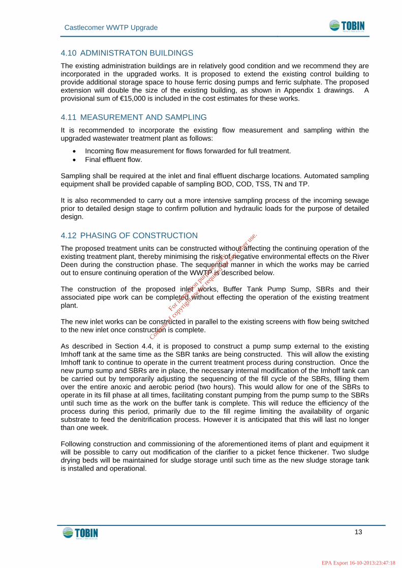
4.10 ADMINISTRATON BUILDINGS The existing administration buildings are in relatively good condition and we recommend they are incorporated in the upgraded works. It is proposed to extend the existing control building to provide additional storage space to house ferric dosing pumps and ferric sulphate. The proposed extension will double the size of the existing building, as shown in Appendix 1 drawings. A provisional sum of €15,000 is included in the cost estimates for these works. 4.11 MEASUREMENT AND SAMPLING It is recommended to incorporate the existing flow measurement and sampling within the upgraded wastewater treatment plant as follows:
• Incoming flow measurement for flows forwarded for full treatment. • Final effluent flow.
Sampling shall be required at the inlet and final effluent discharge locations. Automated sampling equipment shall be provided capable of sampling BOD, COD, TSS, TN and TP. It is also recommended to carry out a more intensive sampling process of the incoming sewage prior to detailed design stage to confirm pollution and hydraulic loads for the purpose of detailed design. 4.12 PHASING OF CONSTRUCTION The proposed treatment units can be constructed without affecting the continuing operation of the existing treatment plant, thereby minimising the risk of negative environmental effects on the River Deen during the construction phase. The sequential manner in which the works may be carried out to ensure continuing operation of the WWTP is described below. The construction of the proposed inlet works, Buffer Tank Pump Sump, SBRs and their associated pipe work can be completed without effecting the operation of the existing treatment plant. The new inlet works can be constructed in parallel to the existing screens with flow being switched to the new inlet once construction is complete. As described in Section 4.4, it is proposed to construct a pump sump external to the existing Imhoff tank at the same time as the SBR tanks are being constructed. This will allow the existing Imhoff tank to continue to operate in the current treatment process during construction. Once the new pump sump and SBRs are in place, the necessary internal modification of the Imhoff tank can be carried out by temporarily adjusting the sequencing of the fill cycle of the SBRs, filling them over the entire anoxic and aerobic period (two hours). This would allow for one of the SBRs to operate in its fill phase at all times, facilitating constant pumping from the pump sump to the SBRs until such time as the work on the buffer tank is complete. This will reduce the efficiency of the process during this period, primarily due to the fill regime limiting the availability of organic substrate to feed the denitrification process. However it is anticipated that this will last no longer than one week. Following construction and commissioning of the aforementioned items of plant and equipment it will be possible to carry out modification of the clarifier to a picket fence thickener. Two sludge drying beds will be maintained for sludge storage until such time as the new sludge storage tank is installed and operational.
For
insp
ectio
n pur
pose
s only
.
Conse
nt of
copy
right
owne
r req
uired
for a
ny ot
her u
se.
EPA Export 16-10-2013:23:47:18

Castlecomer WWTP Upgrade
14
4.13 ENVIRONMENTAL IMPACT The recommended upgrading works will have a positive effect on the River Deen and will help the river to comply with the relevant EU Directives, National Legislation. The proposed upgrade of the overflow at the siphons upstream of the treatment plant will need to ensure that flows discharged to the river will be equivalent to having passed through a 6mm screen with 90% of the grit in the combined flows being retained in the flow sent forward for full treatment. This will significantly improve the quality of the storm overflow to the River Deen at this location. The construction works associated with the proposed plant upgrade are relatively minor. However, there are elements of the recommended works which may be constructed above ground and these would have a visual impact. The recommended augmentations of the existing treatment units do not represent a serious visual impact. The new SBRs are the most significant visual impact as these will be located partially / fully above ground. However the site is located in a secluded location surrounded by tall vegetation and trees and it is therefore not envisaged that there will be any issue with it imposing a significant visual impact. Noise impact from the plant will evidently be higher during the construction phase. The contractor must adhere to S.I. 371 of 2006 – SHWW Control of Noise at Work Regulations 2006 during the construction period. During the operation of the plant the most significant noise impact will be from the air blowers, which typically generate noise levels at source in the range of 75-80dB (A). This will be reduced by acoustic covers to 65dB(A) – 70dB(A) at source and 45dB (A) at a distance of 50m from the blowers. 4.14 OPERATIONAL MANAGEMENT The recommended process option will have similar operational and management requirements to treatment plants already operated by Kilkenny County Council at Stoneyford and Urlingford and will require a caretaker to supervise and carryout necessary routine maintenance. It is proposed that the operation of the SBRs will be automated to provide an effective sludge age of 7.06 days. The upper concentration of biomass (MLSS) that can be sustained in the reactors at this sludge age is calculated to be 5,487mg/l TSS. The suggested range for the MLSS concentration in SBRs is 2,500 to 5,000mg/l. It is recommended that a two month operation period be included in the contract for the detailed design of the upgrade to the plant. During this period the optimum operational parameters, including MLSS, can be determined in order to provide the minimum sludge age required for nitrogen removal.
For
insp
ectio
n pur
pose
s only
.
Conse
nt of
copy
right
owne
r req
uired
for a
ny ot
her u
se.
EPA Export 16-10-2013:23:47:18

Castlecomer WWTP Upgrade
15
5 COST ESTIMATES In order to fully evaluate the recommended upgrade option an economic analysis of the capital and operational costs has been carried out. These cost estimates are the primary factor in determining the viability of the proposed process option layout but consideration was also given to the criteria outlined in Section 4.12 to determine the overall suitability of the recommended option.
5.1 CAPITAL COSTS Table 5.1 details the Capital Costs for the recommended process option considered for the upgrading of the Castlecomer wastewater treatment plant. A more detailed cost breakdown, including an estimation of life cycle costs, is provided within Appendix 2.
Table 5.1 – Summary of Capital Costs Description Cost
Siphon Overflow Rehabilitation €52,500
Civil Works for Main Treatment Works €302,200
Mechanical & Electrical Works for Main Treatment Works €95,000
General Items (Allow 20%) €89,940
Sub-Total €539,640
VAT @ 13.5% €72,851
Total Cost of Scheme incl. VAT €612,491, say €612,000
Non-Contract Costs €105,000
Total Gross Cost of Scheme (incl. VAT) €717,000
5.2 OPERATION AND MAINTENANCE COSTS Table 5.2 details the Operation and Maintenance Costs for the recommended process option. A more detailed breakdown is included in Appendix 2.
Table 5.2 – Summary of Operation and Maintenance Costs Description Cost (incl VAT)
Annual Electrical Charges €21,632
Consumables €7,500
Sludge Transport Costs €3,000
Variable Costs Sub-Total €33,562
Fixed Costs (Operation & Maintenance) €25,000
Total Annual Running Costs €57,132
NPV for 20 years @ 5% Discount Rate €711,995
For
insp
ectio
n pur
pose
s only
.
Conse
nt of
copy
right
owne
r req
uired
for a
ny ot
her u
se.
EPA Export 16-10-2013:23:47:18

Castlecomer WWTP Upgrade
16
6 STATUTORY REGULATIONS 6.1 ENVIRONMENTAL CONSTRAINTS AND EIS It is not expected that a full Environmental Impact Statement will be required for the scheme as currently proposed. 6.2 WASTE WATER DISCHARGE APPLICATION As stated in Section 1.1 of this Report, Kilkenny County Council applied to the EPA for a Waste Water Discharge License for the agglomeration of Castlecomer in September 2008 (Registration No. D0149-01). The application is still under assessment by the EPA. 6.3 PART 8 PLANNING PERMISSION All of the proposed above ground works will require planning permission under Article 80 Part 8 of the Planning and Development Regulations 2001, SI 61 of 2001. Therefore the proposed upgrade of the treatment plant will require planning permission under these Regulations. It is not anticipated that the works at the proposed overflow will need to be included in the Part 8 Planning process. 6.4 LAND ACQUISITION / WAYLEAVES The Scheme as proposed will require a wayleave at the proposed upgrade works at the storm overflow at the siphons. The length and location of the wayleave will depend upon the final configuration of the overflow arrangement.
For
insp
ectio
n pur
pose
s only
.
Conse
nt of
copy
right
owne
r req
uired
for a
ny ot
her u
se.
EPA Export 16-10-2013:23:47:18

Castlecomer WWTP Upgrade
17
7 SUMMARY AND RECOMMENDATIONS The recommended upgrade works represent a cost effective solution and will help improve the water quality in the River Deen. The capacity of the upgraded treatment works will be increased to achieve BOD and Nutrient removal for 2,500p.e. and the selected treatment process has been designed to achieve a final effluent standard of 15mg/l BOD, 3mg/l Ammonia-N and 1.5mg/l Orthophosphate. As required by the brief we have carried out the following:
• Technical assessment of the existing infrastructure. • Outlined and evaluated acceptable treatment options to achieve the effluent quality
standards. • Recommended and priced a cost effective treatment option.
In accordance with the brief we now make the following key recommendations:
1. A more intensive survey will be carried out on incoming flows to the WWTP, prior to the detailed design stage, to determine more accurately the pollution and hydraulic loads arriving at the plant. The results of this survey will be incorporated into the Design Build contract documents.
2. It is proposed to upgrade the Siphon by providing a SwirlFlo overflow and Hydrobrake at the upstream end of the siphon crossing. The upgrade will improve the quality of the existing storm overflow and should cater for a PWWF, estimated as 3,026m³/d for the purpose of this report but to be confirmed by a more intensive flow measurement survey.
3. It is recommended that a new inlet works be constructed to provide a 6mm vertical band screen, with associated collection facilities. These will cater for 3 DWF with flexibility for expansion to cater for PWWF in the future should the Siphon crossing be removed as a hydraulic constraint.
4. It is recommended that grit removal facilities be included to cater for PWWF in anticipation of future works at the Siphon crossing resulting in all PWWF being carried to the inlet works.
5. It is recommended that the existing Imhoff Tank is modified to operate as a Buffer Tank. This will involve the construction of an external forward feed pump sump and the modification of the existing tank including the installation of a mixer.
6. The provision of two new SBRs, with a capacity of 502m³ each (10.8m dia., 5.5m deep), is recommended.
7. It is recommended that the existing Clarifier is retrofitted to operate as a Picket Fence Thickener, by raising the side-wall by 1m and roofing the structure.
8. The provision of Ferric dosing facilities for Phosphorous removal is recommended, to be housed in an extension to the existing control building. Dosing will be required at a rate of 12.25kg Fe/d.
9. It is recommended that a new sludge storage tank is installed with a capacity of 196m³.
10. The capital cost estimate for the Improvement to Castlecomer Waste Water Treatment Works has been estimated as €717,000 inclusive of VAT.
11. The annual operation and maintenance cost estimate for the proposed upgraded treatment process has been estimated as €57,132 inclusive of VAT.
For
insp
ectio
n pur
pose
s only
.
Conse
nt of
copy
right
owne
r req
uired
for a
ny ot
her u
se.
EPA Export 16-10-2013:23:47:18

Castlecomer WWTP Upgrade - Appendices
APPENDIX 1
DRAWINGS
6676-1000 – Layout of Existing Castlecomer Wastewater Treatment Plant 6676-1001 – Layout of Proposed Upgrade Works 6676-2300 – Layout of WWTW Showing Cross Section Locations 6676-2301 – Cross Section of Existing & Proposed Works 6676-2302 – Cross Section of SBR & Sludge Thickener
For
insp
ectio
n pur
pose
s only
.
Conse
nt of
copy
right
owne
r req
uired
for a
ny ot
her u
se.
EPA Export 16-10-2013:23:47:18

For
insp
ectio
n pur
pose
s only
.
Conse
nt of
copy
right
owne
r req
uired
for a
ny ot
her u
se.
EPA Export 16-10-2013:23:47:19

For
insp
ectio
n pur
pose
s only
.
Conse
nt of
copy
right
owne
r req
uired
for a
ny ot
her u
se.
EPA Export 16-10-2013:23:47:19

For
insp
ectio
n pur
pose
s only
.
Conse
nt of
copy
right
owne
r req
uired
for a
ny ot
her u
se.
EPA Export 16-10-2013:23:47:19

For
insp
ectio
n pur
pose
s only
.
Conse
nt of
copy
right
owne
r req
uired
for a
ny ot
her u
se.
EPA Export 16-10-2013:23:47:19

For
insp
ectio
n pur
pose
s only
.
Conse
nt of
copy
right
owne
r req
uired
for a
ny ot
her u
se.
EPA Export 16-10-2013:23:47:19

Castlecomer WWTP Upgrade - Appendices
APPENDIX 2
COST ESTMATES
CAPITAL COSTS OPERATIONAL COSTS
AND LIFE CYCLE COSTS
For
insp
ectio
n pur
pose
s only
.
Conse
nt of
copy
right
owne
r req
uired
for a
ny ot
her u
se.
EPA Export 16-10-2013:23:47:19

ESTIMATE OF CAPITAL COSTS
SIPHON OVERFLOW REHABILITATION1 Swirl Cleanse Overflow € 35,000.002 Hydrobrake € 7,500.003 Sewer realignment € 10,000.00
Total Cost of Overflow Rehab = € 52,500.00
TREATMENT WORKS
1 Preliminary Treatment Units € 60,000.00
2 Construct Buffer Pump Sump € 7,500.00
3 2 No. SBR tanks € 96,000.00
4 Modify Flow Splitter and Percolating Filters € 15,000.00
5 Modify Clarifier for use as Picket Fence Thickener € 25,000.00
6 Interconnecting Pipework € 31,200.00
7 Control Building € 15,000.00
8 Ferric Dosing Pumps € 5,000.00
9 WAS Pump Sump € 7,500.00
10 Sludge Holding Tank € 25,000.00
11 Site Development and Access Road Improvement € 15,000.00
12 Mechanical and Electrical Plant € 95,000.00
Sub Total for WWTP = € 397,200.00Total Cost of Overflow Rehab = € 52,500.00
€ 449,700.00Allow 20% for General Items on Treatment Works € 89,940.00Estimated Cost excl. VAT € 539,640.00
Add VAT @ 13.5% € 72,851.40
TOTAL COST OF SCHEME (incl. VAT) € 612,491.40 say € 612,000.00
€10,000.00€35,000.00€10,000.00€5,000.00
€40,000.00€5,000.00
Total Non Contract Costs €105,000.00TOTAL GROSS COST OF SCHEME (incl. VAT) € 717,000.00
Engineering FeesWayleaves and Land Acquisition Legal FeesSite Supervisory Staff SalaryTravel & Miscellaneous Expenses
Site InvestigationNON CONTRACT COSTS
For
insp
ectio
n pur
pose
s only
.
Conse
nt of
copy
right
owne
r req
uired
for a
ny ot
her u
se.
EPA Export 16-10-2013:23:47:19

ESTIMATE OF OPERATIONAL COSTS
SEWAGE TREATMENT WORKSVARIABLE COSTSEstimate of Electricity Charges
Unit Estimated Power Operating Time (hrs/day)Total Daily Power Usage
(kWh/day)Treatment WorksFine raked screens drive 0.70 kW 24 16.80Fine raked screens rotary brush 0.50 kW 24 12.00Washpactor impeller 5.00 kW 5 25.00Washpactor blower 0.50 kW 5 2.50Grit trap impeller 0.40 kW 24 9.60Grit trap blower 4.20 kW 5 21.00Screw classifier 0.18 kW 5 0.90Actuated valves 0.15 kW 1 0.15Air blowers 15.00 kW 24 360.00WAS pumps 2.50 kW 2 5.00Supernatant return pump 1.50 kW 12 18.00Final effluent return pumps 5.00 kW 2 10.00Thickened activated sludge pumps 1.50 kW 4 6.00Picket fence thickener 0.30 kW 24 7.20Ferric dosing pumps 0.20 kW 24 4.80Domestic electrics 5.00 kW 3 15.00
TOTAL 513.95Total kWh per year (Pump Stations and Treatment Works) = 187591.75
Annual Electrical Charges excl. VAT = €19,059.32Add VAT @ 13.5% = €2,573.01
Annual Electrical Charges incl. VAT = €21,632.33Consumables
Total Cost of Consumables = €7,500.00Sludge Transport Costs
Assuming 1 trip per month Castlecomer - Purcellsinch @ 250 Euro per trip €3,000.00TOTAL VARIABLE COSTS = €32,132.33
FIXED COSTSOperation and Maintenance
Estimated Operational and Maintenance (Labour) Cost = €25,000.00TOTAL FIXED COSTS = €25,000.00
Total Estimated Running Costs at Sewage Treatment Plant = €57,132.33NPV for 20 years @ 5% Discount Rate = €711,995.10
For
insp
ectio
n pur
pose
s only
.
Conse
nt of
copy
right
owne
r req
uired
for a
ny ot
her u
se.
EPA Export 16-10-2013:23:47:19

PW = Present Worth PWA = Present Worth of Annuity
Item:Life Cycle Period: 20 years Date: Dec 2011 ESTIMATED COSTS PRESENT WORTH
Base Cost a) Total Cost of Overflow Rehab = 52,500€ b) Preliminary Treatment Units 60,000€ c) Modify Imhoff Tanks 7,500€ d) 2 No. SBR tanks 96,000€ e) Modify Flow Splitter and Percolating Filters 15,000€ f) Modify Clarifier for use as Picket Fence Thickener 25,000€ g) Interconnecting Pipework 31,200€ h) Control Building 15,000€ j) Ferric Dosing Pumps 5,000€ k) WAS Pump Sump 7,500€ l) Sludge Holding Tank 25,000€ m) Site Development and Access Road Improvement 15,000€ n) Mechanical and Electrical Plant 95,000€ o) General Items 89,940€
Sub Total 539,640€ Vat @ 13.5% 72,851€ Total incl VAT 612,491€
p) Non Contract Costs 105,000€ Total Initial Cost Impact (IC) 717,491€ 717,491€
Single Expenditure @ 5% Interest1. Year 7 PW factor = 0.71068133 20,000€ 14,214€ 2. Year 14 0.505067953 20,000€ 10,101€ Total Present Worth 24,315€ Annual Costs @ 5% Interest
PWA factorEscal Rate 0% 12.46221034 21,632€ 269,587€ b) Staffing Costs PWA factorEscal Rate 0% 12.46221034 25,000€ 311,555€ c) Sludge Disposal Costs PWA factorEscal Rate 0% 12.46221034 3,000€ 37,387€ d) Consumables PWA factorEscal Rate 0% 12.46221034 7,500€ 93,467€ Total Annual Cost 57,132€ Total Annual Cost (PW) over Life Cycle 711,995€ Total Present Worth Costs 1,453,801€
Castlecomer WWTW
Capital Costs
Replacement Costs
Annual Costs
a) WWTW Electrical Costs
Life Cycle Cost Analysis of Proposed Castlecomer WWTP Upgrade
For
insp
ectio
n pur
pose
s only
.
Conse
nt of
copy
right
owne
r req
uired
for a
ny ot
her u
se.
EPA Export 16-10-2013:23:47:19

Castlecomer WWTP Upgrade - Appendices
APPENDIX 3
DESIGN CALCULATIONS
For
insp
ectio
n pur
pose
s only
.
Conse
nt of
copy
right
owne
r req
uired
for a
ny ot
her u
se.
EPA Export 16-10-2013:23:47:19

Castlecomer WWTP Upgrade - Appendices
Design Calculations for SBR Treatment at Castlecomer
Design Parameter Magnitude
Design Input Data
DWF 575m³/d
Max Flow to Treatment (3 DWF) 1,725m³/d
Population Equivalent 2,500p.e.
Design BOD Load 150kg/d
Design COD Load 337kgCOD/d (586mg/l COD)
Design TN Concentration 46mg/l TN
Design TP Concentration 9mg/l TP
Effluent Quality Standards BOD 15 mg/l BOD
Total Ammonia 3 mg/l N
Orthophosphate 1.5 mg/l P
Nitrate 10 mg/l N
Design of SBRs
Key Design Parameters
Aerobic Sludge Age (�XA) 6 days
Effluent Ammonium Nitrogen (SNH) 2.6 mg/l N
Anoxic Sludge Fraction (TAOX / TE) 0.15
Effective Sludge Age 7.06 days
Denitrification Potential (NDP) 17.9mg/l N
Required Available Nitrate (NA) 15.6mg/l N
Denitrification Efficiency (EP) 61%
Required Recycle Ratio (R) 1.56
Effluent Nitrate Nitrogen (SNO) 10mg/l N
Cycle Timing
Cycle Time (TC) 4 hrs
Duration of Settle Draw and Idle Phases (TS+D+i) 2 hrs
Effective Cycle Time (TE) 2 hrs
Anoxic Time (TAOX) 0.3 hrs
Aerobic Time (TA) 1.7 hrs
Critical Tank Dimensioning Data
Recycle Ratio (V0 / VF) 2.49
Hydraulic Retention Time (�H) 13.95hrs
For
insp
ectio
n pur
pose
s only
.
Conse
nt of
copy
right
owne
r req
uired
for a
ny ot
her u
se.
EPA Export 16-10-2013:23:47:19
Castlecomer WWTP Upgrade - Appendices
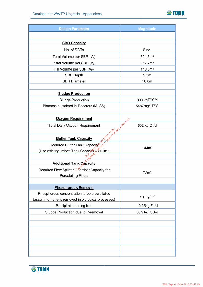
Design Parameter Magnitude
SBR Capacity
No. of SBRs 2 no.
Total Volume per SBR (VT) 501.5m³
Initial Volume per SBR (V0) 357.7m³
Fill Volume per SBR (VF) 143.8m³
SBR Depth 5.5m
SBR Diameter 10.8m
Sludge Production
Sludge Production 390 kgTSS/d
Biomass sustained in Reactors (MLSS) 5487mg/l TSS
Oxygen Requirement
Total Daily Oxygen Requirement 652 kg O2/d
Buffer Tank Capacity
Required Buffer Tank Capacity
(Use existing Imhoff Tank Capacity = 321m³) 144m³
Additional Tank Capacity
Required Flow Splitter Chamber Capacity for
Percolating Filters 72m³
Phosphorous Removal
Phosphorous concentration to be precipitated
(assuming none is removed in biological processes) 7.9mg/l P
Precipitation using Iron 12.25kg Fe/d
Sludge Production due to P-removal 30.9 kgTSS/d
For
insp
ectio
n pur
pose
s only
.
Conse
nt of
copy
right
owne
r req
uired
for a
ny ot
her u
se.
EPA Export 16-10-2013:23:47:19

Castlecomer WWTP Upgrade - Appendices
Design Parameter Magnitude
Sludge Handling Facilities
Sludge Thickeners
Total Sludge Production 421kgTSS/d
No. of Thickeners 1 no.
Solids Flux Rate 30 kg/m²/d
Minimum Surface Area Required per Thickener 14m²
Minimum Diameter Required per Thickener 4.2m
Minimum Depth of Thickener 3.5m
Modify Existing Clarifier to Operate as PFT by raising side wall by 1m and roofing
Sludge Holding Tank
Volume at Dry Solids Content of 3% 14m³/d
No. of Days Storage to be provided 14days
Required Sludge Storage Capacity 196m³
For
insp
ectio
n pur
pose
s only
.
Conse
nt of
copy
right
owne
r req
uired
for a
ny ot
her u
se.
EPA Export 16-10-2013:23:47:19

Castlecomer WWTP Upgrade - Appendices
APPENDIX 4
TREATED EFFLUENT RESULTS
For
insp
ectio
n pur
pose
s only
.
Conse
nt of
copy
right
owne
r req
uired
for a
ny ot
her u
se.
EPA Export 16-10-2013:23:47:19
Castlecomer WWTP Upgrade - Appendices
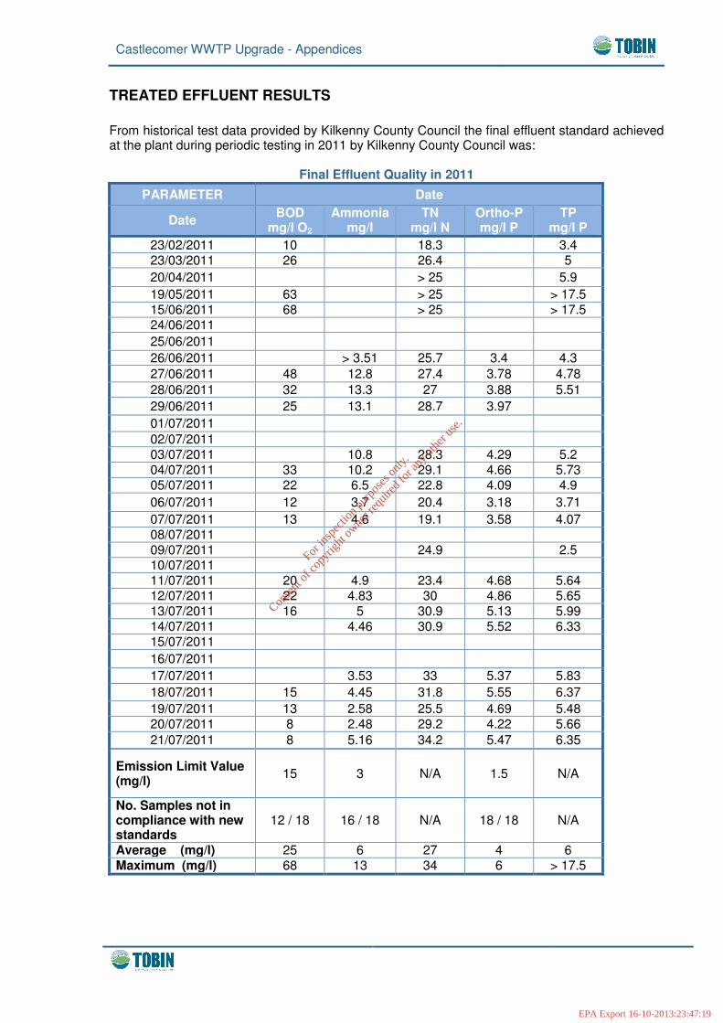
TREATED EFFLUENT RESULTS From historical test data provided by Kilkenny County Council the final effluent standard achieved at the plant during periodic testing in 2011 by Kilkenny County Council was:
Final Effluent Quality in 2011 PARAMETER Date
Date BOD mg/l O2
Ammonia mg/l
TN mg/l N
Ortho-P mg/l P
TP mg/l P
23/02/2011 10 18.3 3.4 23/03/2011 26 26.4 5 20/04/2011 > 25 5.9 19/05/2011 63 > 25 > 17.5 15/06/2011 68 > 25 > 17.5 24/06/2011 25/06/2011 26/06/2011 > 3.51 25.7 3.4 4.3 27/06/2011 48 12.8 27.4 3.78 4.78 28/06/2011 32 13.3 27 3.88 5.51 29/06/2011 25 13.1 28.7 3.97 01/07/2011 02/07/2011 03/07/2011 10.8 28.3 4.29 5.2 04/07/2011 33 10.2 29.1 4.66 5.73 05/07/2011 22 6.5 22.8 4.09 4.9 06/07/2011 12 3.7 20.4 3.18 3.71 07/07/2011 13 4.6 19.1 3.58 4.07 08/07/2011 09/07/2011 24.9 2.5 10/07/2011 11/07/2011 20 4.9 23.4 4.68 5.64 12/07/2011 22 4.83 30 4.86 5.65 13/07/2011 16 5 30.9 5.13 5.99 14/07/2011 4.46 30.9 5.52 6.33 15/07/2011 16/07/2011 17/07/2011 3.53 33 5.37 5.83 18/07/2011 15 4.45 31.8 5.55 6.37 19/07/2011 13 2.58 25.5 4.69 5.48 20/07/2011 8 2.48 29.2 4.22 5.66 21/07/2011 8 5.16 34.2 5.47 6.35
Emission Limit Value (mg/l) 15 3 N/A 1.5 N/A
No. Samples not in compliance with new standards
12 / 18 16 / 18 N/A 18 / 18 N/A
Average (mg/l) 25 6 27 4 6 Maximum (mg/l) 68 13 34 6 > 17.5
For
insp
ectio
n pur
pose
s only
.
Conse
nt of
copy
right
owne
r req
uired
for a
ny ot
her u
se.
EPA Export 16-10-2013:23:47:19