lifante frank cavitation mpf07 final
TRANSCRIPT

© 2006 ANSYS, Inc. All rights reserved. ANSYS, Inc. Proprietary
Extension and Validation of the CFX Cavitation Model for Sheet and Tip Vortex Cavitation on Hydrofoils
Extension and Validation of the CFX Cavitation Model for Sheet and Tip Vortex Cavitation on Hydrofoils
C. Lifante, T. Frank, M. KuntzANSYS Germany, 83624 [email protected]
C. Lifante, T. Frank, M. KuntzANSYS Germany, 83624 [email protected]

© 2006 ANSYS, Inc. All rights reserved. 2 ANSYS, Inc. Proprietary
OverviewOverview
• Introduction
• Cavitation project
– Goals
– Cavitation model
– Testcases
• Results
– Testcase set-up
– Validation studies
• Summary

© 2006 ANSYS, Inc. All rights reserved. 3 ANSYS, Inc. Proprietary
Cavitation on Pumps, Propellers
& Hydrofoils
Cavitation on Pumps, Propellers
& Hydrofoils
• Cavitation phenomena
• Propeller
– Tip vortex cavitation
• Hydrofoil
– Sheet & cloud cavitation

© 2006 ANSYS, Inc. All rights reserved. 4 ANSYS, Inc. Proprietary
Cavitation ProjectCavitation Project
• Title– Investigation of higher order pressure fluctuations
and its influence on ship stern, taking into account cavitation at propeller blades
• Project partners– SVA Potsdam, ANSYS Germany
• Duration– July 2005 to June 2008
• Funded by German Ministry of Education and Research (BMBF)
• Main issues– CFD & experiments for ship propeller cavitation– Cavitation including transient effects– Cavitation induced pressure fluctuations and
interaction with ship stern

© 2006 ANSYS, Inc. All rights reserved. 5 ANSYS, Inc. Proprietary
Cavitation Model-Rayleigh-Plesset
Equation
Cavitation Model-Rayleigh-Plesset
Equation
• Interfacial mass transfer
lv lv lvm AΓ = ɺ
vlv v
dm dRm
dt dt= = ρɺ
R, dR/dt
N
v
l
dR 2 P P
dt 3
−=
ρ

© 2006 ANSYS, Inc. All rights reserved. 6 ANSYS, Inc. Proprietary
Cavitation Model-Rayleigh-Plesset
Equation
Cavitation Model-Rayleigh-Plesset
Equation
( )nuc v vlv vap v v
l
v vvl con v v
l
3 1 P P2F if P P
R 3
3 P P2F if P P
R 3
α − α −Γ = ρ <
ρ
α −Γ = − ρ >
ρ
• Modified interfacial area density for vapourisation
• Fvap = 50, Fcon = 0.01
• ααααnuc = 5 ×××× 10-4

© 2006 ANSYS, Inc. All rights reserved. 7 ANSYS, Inc. Proprietary
Turbulent Pressure FluctuationsTurbulent Pressure Fluctuations
Pressure fluctuations in the (U)RANS equations:
Where
Therefore:
P P p′= +
2 2 2 2(1 ) (1 )1
( )2
coef coefv vp p CAV k CAV u v wρ ρα α′ ′ ′ ′= = + +− −ɶ ∼
2( )
3
v
l
dR P P p
dt ρ
− −=
ɶ0.39coefCAV =

© 2006 ANSYS, Inc. All rights reserved. 8 ANSYS, Inc. Proprietary
Project TestcasesProject Testcases
Arndt: 3D profile
Le: 2D profile

© 2006 ANSYS, Inc. All rights reserved. 9 ANSYS, Inc. Proprietary
Le ProfileLe Profile
• Measurements of Le et al. (1993) & Franc (2001)
– Two-dimensional profile
– Different cavitation phenomena
20.5
vP P
vσ
ρ∞
∞
−=

© 2006 ANSYS, Inc. All rights reserved. 10 ANSYS, Inc. Proprietary
Set-up: Boundary ConditionsSet-up: Boundary Conditions
• Inlet: Specified velocity (from Reynolds number)
• Walls: Free slip
• Outlet: Static pressure for entrainment
inlet outletsymmetry planes
b
1.9 m0.5 m
wall
wall
b

© 2006 ANSYS, Inc. All rights reserved. 11 ANSYS, Inc. Proprietary
Meshing: Grid HierarchyMeshing: Grid Hierarchy
893,986224,26456,452Number of nodes
2
5
38°
111,360
Medium(3)
2.510First layer distance
y [µµµµm]
14Average y+
43°41°Minimum grid angle
445,44027,840Number of elements
Fine(4)Coarse(2)Grid
• ICEM CFD HEXA
– Geometry rotation for different angle of attack
• 2d refinement between grids by scale factor 2××××2

© 2006 ANSYS, Inc. All rights reserved. 12 ANSYS, Inc. Proprietary
Validation: Cavitation LengthValidation: Cavitation Length
α=4°
σ=0.5
α=0°
σ=0.4
α=-4°
σ=0.3
• Transient simulations,
time averaged data
C0=0.198m

© 2006 ANSYS, Inc. All rights reserved. 13 ANSYS, Inc. Proprietary
Validation: Cavitation LengthValidation: Cavitation Length
• Transient simulation , α=α=α=α=4°, σ=σ=σ=σ=0.5

© 2006 ANSYS, Inc. All rights reserved. 14 ANSYS, Inc. Proprietary
Validation: Pressure DistributionValidation: Pressure Distribution
• Pressure coefficient distribution on foil upper side
• Angle of attack: α=α=α=α=2.5°and α=α=α=α=3.5°
• Transient simulations, time averaged data
20.5p
P Pc
vρ∞
∞
−=

© 2006 ANSYS, Inc. All rights reserved. 15 ANSYS, Inc. Proprietary
• Pressure coefficient distribution on foil upper side• Angle of attack: α=3.5°, σ=0.55
• Transient simulations, time averaged data
Validation: Pressure DistributionValidation: Pressure Distribution
0.0p =ɶ
0.39p kρ=ɶ
(1 )0.39v
p r kρ= −ɶ

© 2006 ANSYS, Inc. All rights reserved. 16 ANSYS, Inc. Proprietary
Arndt ProfileArndt Profile
• Measurements by Arndt, R.E.A. and Dugue (1992)

© 2006 ANSYS, Inc. All rights reserved. 17 ANSYS, Inc. Proprietary
Set-up: Boundary ConditionsSet-up: Boundary Conditions
• Inlet
– Computed from Re number
• Outlet
– Static pressure for entrainment
• Walls
– No slip
Inlet
Outlet
No slip walls
Profile

© 2006 ANSYS, Inc. All rights reserved. 18 ANSYS, Inc. Proprietary
Meshing: TopologyMeshing: Topology
• ICEM CFD structured meshes
– C-Grid type grid around foil surface
– Quarter O-Grid between C and O-Block connection at blade tip

© 2006 ANSYS, Inc. All rights reserved. 19 ANSYS, Inc. Proprietary
Meshing: Grid HierarchyMeshing: Grid Hierarchy
• Boundary layer resolution
– Relation of first cell spacing to y+ value
+−∆=∆ yLy L
14/13Re80
21°21°21°Minimum grid angle
5,442,4591,394,862358,519Number of nodes
7.1
15
1,352,603
Medium (2)
7.530First layer distance y [µµµµm]
3.614.3Average y+
5,337,217341,596Number of elements
Fine (3)Coarse (1)Grid
• Scaling factor between grids ~3 3 34 4 4× ×

© 2006 ANSYS, Inc. All rights reserved. 20 ANSYS, Inc. Proprietary
Set-up: Physical ModelsSet-up: Physical Models
• Spatial discretization
– High Resolution for hydrodynamic system
– Upwind / High Resolution for k-ωωωω equations
• Time integration
– 2nd order Backward Euler
• Two-phase flow
– Water, water vapour
• Mass transfer
– Rayleigh-Plesset cavitation model
• Turbulence
– SST, SST with Curvature Correction, BSL-RSM

© 2006 ANSYS, Inc. All rights reserved. 21 ANSYS, Inc. Proprietary
Validation: Tip Vortex TrajectoryValidation: Tip Vortex Trajectory
• Multiple measurements:
Various Re numbers
Various angle of attack
y/b
x/c0
© 2006 ANSYS, Inc. All rights reserved. 22 ANSYS, Inc. Proprietary
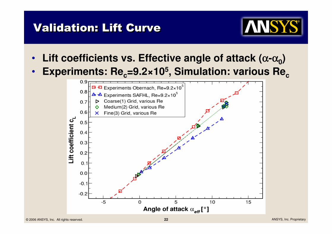
Validation: Lift CurveValidation: Lift Curve
• Lift coefficients vs. Effective angle of attack (αααα-αααα0)
• Experiments: Rec=9.2×10⁵, Simulation: various Rec

© 2006 ANSYS, Inc. All rights reserved. 23 ANSYS, Inc. Proprietary
• Measurement planes
– Evaluation of vortex velocity at plane perpendicular to flow at x/c=0.5, 1.0, 2.0 behind hydrofoil
Validation: Tip Vortex VelocityValidation: Tip Vortex Velocity
x/c0=1
x/c0=2
x/c0=0.5

© 2006 ANSYS, Inc. All rights reserved. 24 ANSYS, Inc. Proprietary
Validation: Tip Vortex VelocityValidation: Tip Vortex Velocity
Experiment x/c0=1.0Coarse(1) x/c0=1.0Medium(2) x/c0=1.0Fine(3) x/c0=1.0
Vortex velocity
distributions
Cavitation inception in
core of tip vortex
αeff=12°, Re=5.2××××105

© 2006 ANSYS, Inc. All rights reserved. 25 ANSYS, Inc. Proprietary
Validation: Tip Vortex VelocityValidation: Tip Vortex Velocity
Turbulence model variation:
• Standard SST model
• Spatial discretization
– High Resolution for all equations except turbulence
– High Resolution for all equations
• Curvature correction
– Turbulence strongly affected by swirl and streamline curvature
– Effects are not accounted for in standard 2-equation model
– Additional terms in SST turbulence equations
• BSL-RSM model
– One equation for each stress tensor component

© 2006 ANSYS, Inc. All rights reserved. 26 ANSYS, Inc. Proprietary
SST (Fine)
SST High Res (Fine)
SST High Res CC (Fine)
RSM (Medium)
RSM (Coarse)
Experiment
Vel
oci
ty w
/u∞
_
Validation: Tip Vortex VelocityValidation: Tip Vortex Velocity
αeff=12°, Re=5.2××××105
SST
+ High Resolution for turbulence equations
+ Curvature correction terms
BSL-RSM

© 2006 ANSYS, Inc. All rights reserved. 27 ANSYS, Inc. Proprietary
Tip Vortex Tip Vortex Tip Vortex Tip Vortex VapourVapourVapourVapour volume fractionvolume fractionvolume fractionvolume fractionTip Vortex Tip Vortex Tip Vortex Tip Vortex VapourVapourVapourVapour volume fractionvolume fractionvolume fractionvolume fraction
• Medium grid
• Re=5.2x10⁵
• αeff=12°, σ=0.58
SST RSM
αeff=9.5°, σ=0.58, Re=5.2x10⁵
© 2006 ANSYS, Inc. All rights reserved. 28 ANSYS, Inc. Proprietary
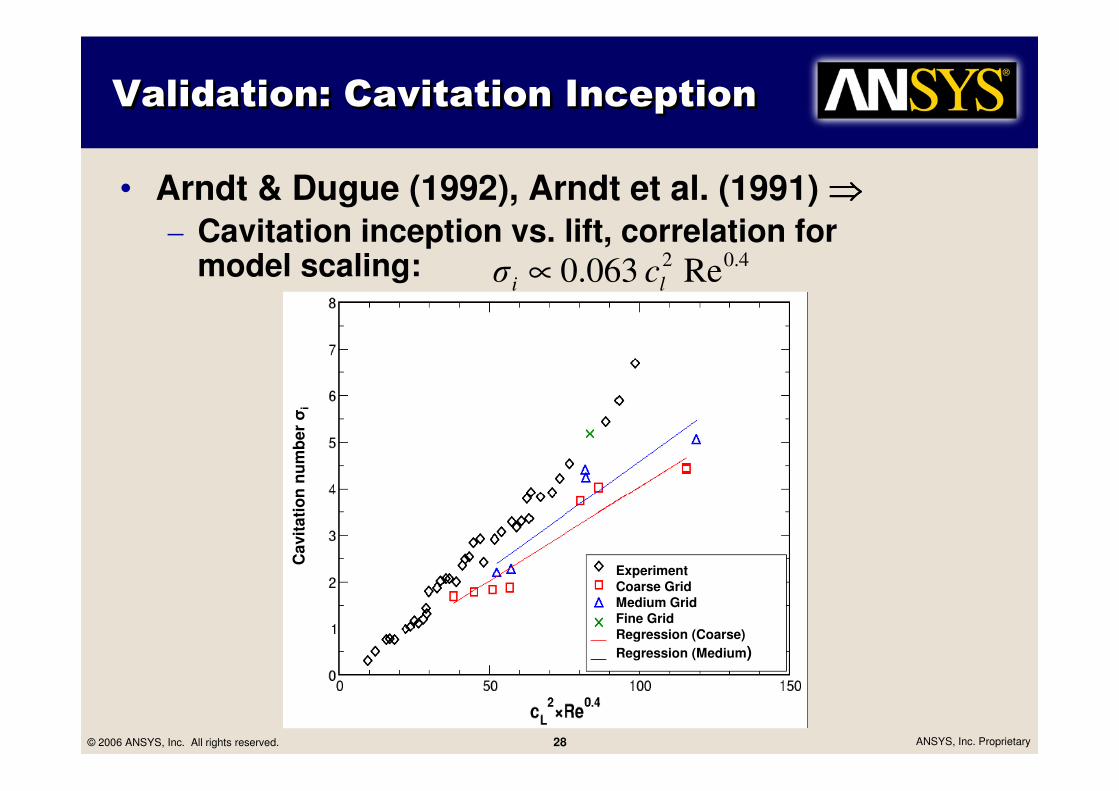
Validation: Cavitation InceptionValidation: Cavitation Inception
• Arndt & Dugue (1992), Arndt et al. (1991) ⇒⇒⇒⇒
– Cavitation inception vs. lift, correlation for model scaling: 4.02 Re063.0 li c∝σ
Ca
vit
ati
on
nu
mb
er σ
i
ExperimentCoarse GridMedium GridFine GridRegression (Coarse)
Regression (Medium)

© 2006 ANSYS, Inc. All rights reserved. 29 ANSYS, Inc. Proprietary
SummarySummary
• SVA Potsdam & ANSYS Germany cavitation project (BMBF)
• ANSYS CFX cavitation model
• Validation test cases for hydrofoil cavitation:
– Le et al. ���� 2d hydrofoil cavitation
– Arndt et al. ���� tip vortex cavitation
• Work in progress
– Isolated propeller P1356
– Non condensible gas cavitation
– Ship propeller with ship stern.
• Rotor-Stator interface
• Influence of the turbulence model

© 2006 ANSYS, Inc. All rights reserved. 30 ANSYS, Inc. Proprietary
Thank You!