lift, stairwell & service shafts - dpo.com.au shaft... · 4 gyprock® shaft systems system...
TRANSCRIPT
Shaft SystemsLift, Stairwell & Service Shafts
GYP546 JUNE 2005
EV
ER
YT
HIN
G E
LS
E IS
JU
ST
PLA
ST
ER
BO
AR
D

Gyprock® Shaft Systems2
ContentsIntroduction 2
Typical Applications for Gyprock Shaft Systems 3
System Performance 4
Advantages 5
Design Considerations 5
Gyprock® Plasterboard & Accessories 6 – 8
Architectural Specification 9
System Selection 10 – 11
Shaftwall System Tables 12
Laminated Service Shaft System Tables 13
Steel Stud System Tables 13
Shaftwall System Installation 14 – 17
Wall Junction Details 17 – 20
Access Doorways 21
Lift Landing Doorways 22
Access Panels & Frames 23
System Installation Details 24 – 27
Contact, Safety & Guarantee Information 28
IntroductionGyprock® Shaft Systems are non loadbearing, fire
resistant wall assemblies designed to encase lift shafts, stairwells and service ducting in low and high rise construction.
A comprehensive range of Gyprock® Shaft Systems is available to accommodate most common applications. Systems include Shaftwall Systems for lifts, stairwells and service shafts, and Laminated Service Systems for service shafts.
Shaftwall Systems comprise 25mm thick GYPROCK SHAFT LINER PANEL and 16mm GYPROCK FYRCHEK plasterboard supported by a frame of galvanised steel C-H studs, tracks or angles.
Laminated Service Systems comprise 3 layers of GYPROCK FYRCHEK plasterboard laminated together using screws or screws and glue, and incorporating perimeter steel angle framing.
Gyprock® Shaft Systems are designed predominantly for erection from one side only. Walls are assembled from outside the shaft at each floor, eliminating the need for access or scaffolding within the shaft.
Gyprock® Shaft Systems combine lightweight construction, rapid installation and drywall finishing techniques to offer significant cost savings to builders and developers. These benefits are of particular significance when used in conjunction with structural steel construction.
Gyprock® Shaft Systems3
Services
Tea Room Lobby
Fire EscapeStair 1
Duct
Lift 1(Fire Lift 1)
Lift 2
Lift 3
Fire HoseReel CupboardCorridor
Lift 4
Lift 5
Lift 6
Goods Lift 7(Fire Lift 2)
Female Toilets
Male Toilets
Air
Supply
Air
Return
Ser
vice
Duc
t
Ser
vice
Duc
t
Fire EscapeStair 2
Toi
let
Exh
aust
Air Lock
Lift Lobby
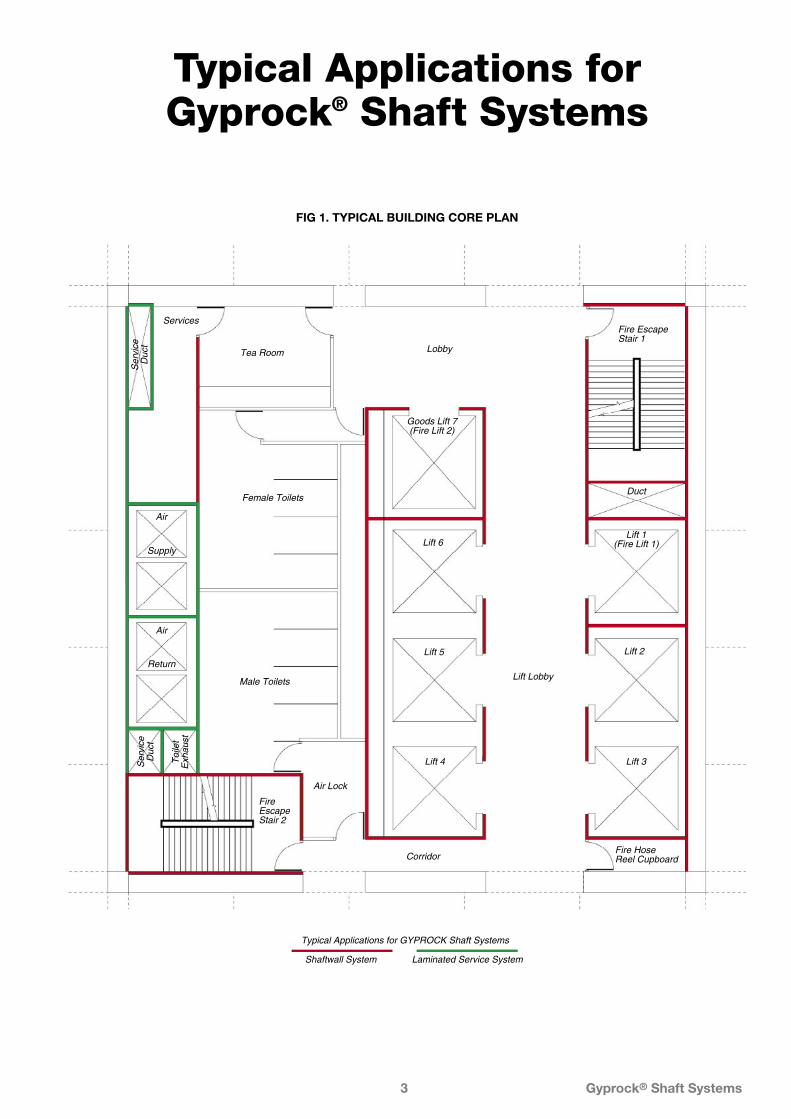
Typical Applications for GYPROCK Shaft Systems
Laminated Service SystemShaftwall System
Typical Applications for Gyprock® Shaft Systems
FIG 1. TYPICAL BUILDING CORE PLAN

Gyprock® Shaft Systems4
System Performance
Construction used to bound means of egress, such as walls enclosing lifts, stairwells and fire-isolated passageways, performs an important function should fire occur.
Such walls provide protection for the fire brigade entering the building to reach a fire, and to the occupants attempting to leave the building. These walls must offer proven fire resistance for the design fire period, including sufficient structural strength to fulfil these functions.
Service shafts are typically enclosures containing electrical, mechanical or hydraulic services between floor levels. Walls for these enclosures may be required to:
• Protect the services from fire.
• Prevent the spread of fire via the service duct.
• Provide acoustic separation between noisy services and building occupants.
The Building Code of Australia specifies the minimum fire resistance level and structural performance requirements of lightweight construction systems when used to protect building components in the various types of buildings.
GYPROCK Shaft Systems are classified as ‘lightweight construction’ under the Building Code of Australia definition, and have been subjected to appropriate testing as required by the Code.
FIRE RESISTANCE
GYPROCK Shaft Systems have been tested in accordance with Australian Standard AS1530 Part 4, and letters of opinion covering minor variations from tested prototypes have been obtained from recognised authorities.
The fire resistance levels quoted for GYPROCK Shaft Systems apply for fire attack from either direction, despite their non-symmetrical nature.
ACOUSTIC PERFORMANCE
Various GYPROCK Shaft System configurations have been laboratory tested for acoustic performance. Testing has been conducted in accordance with the relevant Australian or Overseas Standard applying at the time of testing.
Where test results are not available, estimates calculated by PKA Acoustic Consulting are provided.
THE CSR GYPROCK ACOUSTIC PREDICTOR
CSR Gyprock provides a service which can assist in determining the Rw ratings of stud walls lined with Gyprock® plasterboard that are not published in this guide. Please telephone the CSR designLINK Service on 1800 621 117 for assistance.
STRUCTURAL PERFORMANCE
The Building Code of Australia – Specification C1.8 ‘Structural Tests for Lightweight Construction’, details the tests to be applied and criteria to be satisfied by lightweight wall construction. These four tests are as follows –
Resistance to Static Pressure
Typical wall sections are subjected to a uniformly distributed load (or its equivalent) of 0.25kPa or 0.35kPa depending on the location of the wall and the class of the building in which it is used.
GYPROCK Shaftwall Systems have the proven strength to resist these loads, which are typical of those experienced during the lifetime of the building.
Laminated Service Systems are suitable for 0.25kPa.
Refer to NATA Test Report N°MTO12-90.
Gyprock® Shaft Systems are not suitable for certain walls of Class 9B buildings which require 1.0kPa loading.
Resistance to Impact
A series of impacts from a 27.2kg sandbag are imposed on a typical wall section and must not cause permanent damage.
GYPROCK Shaft Systems combine the structural efficiency of C-H studs or steel angle framing with the strength of plasterboard to satisfy this requirement.
Refer to NATA Test Report N°MTO2-88.
Resistance to Surface Indentation
This test measures the surface hardness of the material.
GYPROCK FYRCHEK and GYPROCK Shaft Liner Panel both satisfy the requirements of this test.
Refer to NATA Test Report N°MTO8-89 and MTO9-89.
Resistance to Repetitive Loads
The movement of high speed lift cars within the shaft of a high rise building exerts positive and negative air pressure forces on the walls enclosing the shaft. These forces have been known to damage rigid masonry enclosures over time.
This test simulates these forces by the imposition of one million cycles of a uniformly distributed load (or its equivalent) between 0 and 0.35kPa.

Gyprock® Shaft Systems5
GYPROCK Shaftwall Systems using C-H stud framing have been subjected to these dynamic tests and have the ability to flex in response to such loads without sustaining damage
Refer to NATA Test Report NºMTO13-90.
AdvantagesRAPID INSTALLATION
GYPROCK Shaft Systems are rapidly installed from one side at each floor, with no need for access within the shaft.
Shafts are rapidly closed in, providing safe work areas for following trades.
As no scaffolding is required within shafts, lifts services can be installed early in the construction program, ready to move men and materials to higher floors as needed.
All components are screw or screw and adhesive fixed, and there is no need for welding or bolting.
LIGHT WEIGHT
GYPROCK Shaft Systems weigh less than 50kg/m2, or approximately 25% of the weight of equivalent masonry or concrete enclosures.
Weight reductions of this magnitude can result in significant cost savings through the complete structure, from structural columns and beams to footing and foundations.
SLENDER WALLS
The reduced floor space required by GYPROCK Shaft Systems means greater net floor areas are available for use/lease.
EASIER MATERIALS HANDLING
Large quantities of metal components and plasterboard sheeting can be transported to site, craned into position and stored on each floor ready for installation with a minimum of disruption to other trades.
DRYWALL CONSTRUCTION
Drywall construction methods eliminate the delays, mess and inconvenience associated with traditional wet trades, and allow the early decoration of finished walls.
Design Considerations
BCA REQUIREMENTS
GYPROCK Shaft Systems are classed as ‘Lightweight Construction’ by the Building Code of Australia. Designers
should ensure that selected wall systems satisfy the fire resistance and structural requirement of the Code for the applications proposed.
AIR MOVEMENT/PRESSURES
GYPROCK Shaftwall Systems used to enclose lift shafts or service ducts must have all perimeters and penetrations effectively sealed with Gyprock® Fire Mastic to eliminate whistling and sound leakage while maintain the stated fire resistance level.
SERVICE DUCTS
GYPROCK Shaft Systems may be used as unlined return air ducts, providing surface air temperatures and humidities do not allow condensation to occur on the faces of the plasterboard linings or the metal framework. These systems are not recommended for use as unlined HVAC supply ducts/shafts.
MOISTURE
Exposure to excessive or continuous moisture or humidity should be avoided both during construction and in service.
Allowance needs to be made for the capping of shafts during the construction phase to ensure installations are not damaged by excessive rainwater.
SERVICE PENETRATIONS
GYPROCK Shaft Systems incorporating access panels, fire dampers, plumbing penetrations and the like, must be detailed to ensure both their fire and structural integrity is maintained.
FIRE DOORS
Proprietary steel door frames as detailed on page 22 and 23 are ordered separately and supplied by the appropriate manufacturer.
LIFT EQUIPMENT
Lift operating equipment should be mounted independently from the shaftwall system.
STRUCTURAL
All GYPROCK Shaft Systems are designed as non loadbearing partitions. It is acceptable however to include loadbearing elements within the system cavity.
GYPROCK Shaft Systems are not intended to provide resistance to in-plane loading (bracing).
PERIMETER FASTENERS
It is important that the project engineer approve the type, size and maximum spacing of perimeter fasteners to meet the design load requirements.
Track fasteners shall be capable of withstanding a minimum of 0.86kN single shear and 0.89kN bearing force.

Gyprock® Shaft Systems6
FIRE RESISTANCE
Gyprock® plasterboard products have been tested to AS1530.3, ‘Simultaneous determination of Ignition, Flame Propagation, Heat Release and Smoke Release. See Table 2 for test results.
TABLE 1. GYPROCK PLASTERBOARD AVAILABILITYGYPROCK plasterboard sheet products have coloured face liners for easy identification
(Applicable colours are shown behind product groups below).
Gyprock® Plasterboard &
AccessoriesCSR Gyprock manufactures a diverse range of
plasterboard sheet products for fire rated and non fire rated applications. Refer to Table 1 for thickness and sheet size availability.
FIRE RATED PLASTERBOARDS
Gyprock Fyrchek™ can be used in wall and ceiling systems where fire resistance is to be achieved and is also useful where improved acoustic performance is required. GYPROCK Fyrchek™ is machine made sheet composed of a specially processed glassfibre reinforced gypsum core encased in a heavy duty liner board.
Gyprock FyrchekMR™ is primarily intended for walls and ceilings in ‘wet area rooms’ and for soffits and external eaves which must also achieve fire resistance. GYPROCK FyrchekMR™ is machine made sheet composed of a specially processed glassfibre reinforced gypsum core encased in a heavy duty liner board. Both the core and the liner board are treated in manufacture to withstand the effects of high humidity and moisture.
Gyprock® Shaft Liner Panel is a 25mm thick machine made sheet composed of a specially processed glass fibre reinforced gypsum core encased in a heavy duty liner board. GYPROCK Shaft Liner Panel is specifically developed to enclose lift shafts, stairwells and service shafts in multistorey construction. GYPROCK Shaft Liner Panel can be used to achieve fire resistance in wall and ceiling systems.
HANDLING & STORAGE
All materials must be kept dry, preferably stored inside. Care should be taken to avoid sagging or damage to ends, edges and surfaces of sheets.
All GYPROCK plasterboard must be stacked flat, properly supported on a level platform or on support members which extend the full width of the sheets and which are spaced at a maximum of 600mm centres.
If stored outside, sheets must be stored off the ground, stacked as previously detailed and protected from the weather.
Support full width of CSR Gyprock® plasterboard sheets
600mmmaximum
FIG 2. STACKING AND SUPPORT OF PLASTERBOARD SHEETS
GYPROCK Product Thicknessmm
Widthmm
Sheet Length (mm) Mass 2400 2700 3000 3600 4200 4800 5400 6000
FYRCHEK 13 1200 ✓ ✓ ✓ 10.5
16 1200 ✓ ✓ ✓ ✓ 12.5
FYRCHEK MR 13* 1200 ✓ ✓ 10.7
16* 1200 ✓ ✓ 13.5
SHAFT LINER PANEL 25 600 ✓ 19.8
The range of stock sheet sizes available may vary from state to state.* FYRCHEK MR is carried in some states. Call your state office for details.
TABLE 2. FIRE HAZARD PROPERTIES.
GYPROCK Product
EFHI SMOGRARC Group Number
13 – 16mm FYRCHEK™ 0/0/0/3 0 1
13 – 16mm FYRCHEK MR™ 13/0/2/2 0 1
25mm SHAFT LINER 0/0/0/3 0 1
NOTES: EFHI = Early Fire Hazard Indices (Ignitability/Spread of Flame/Heat Developed.
SMOGRARC = Smoke Growth Rate Index
Gyprock® Shaft Systems7
SEALANTS
Gyprock® Fire Mastic must be used in fire rated systems where caulking is indicated, and is also recommended for caulking acoustic systems. It is available in 300ml tubes, 600ml sausages or 10 litre buckets.
Promaseal IBS™ Rod (20mm and 29mm dia.) are to be used where indicated.
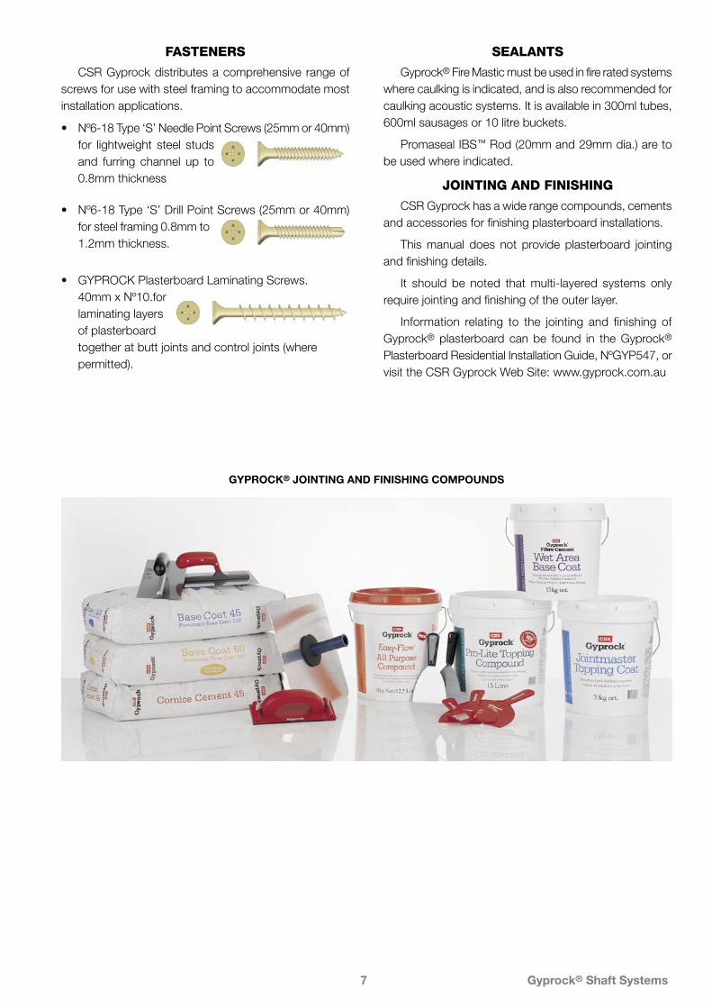
JOINTING AND FINISHING
CSR Gyprock has a wide range compounds, cements and accessories for finishing plasterboard installations.
This manual does not provide plasterboard jointing and finishing details.
It should be noted that multi-layered systems only require jointing and finishing of the outer layer.
Information relating to the jointing and finishing of Gyprock® plasterboard can be found in the Gyprock® Plasterboard Residential Installation Guide, NºGYP547, or visit the CSR Gyprock Web Site: www.gyprock.com.au
FASTENERS
CSR Gyprock distributes a comprehensive range of screws for use with steel framing to accommodate most installation applications.
• Nº6-18 Type ‘S’ Needle Point Screws (25mm or 40mm) for lightweight steel studs and furring channel up to 0.8mm thickness
• Nº6-18 Type ‘S’ Drill Point Screws (25mm or 40mm) for steel framing 0.8mm to 1.2mm thickness.
• GYPROCK Plasterboard Laminating Screws. 40mm x Nº10.for laminating layers of plasterboard together at butt joints and control joints (where permitted).
GYPROCK® JOINTING AND FINISHING COMPOUNDS
Gyprock® Shaft Systems8
STEEL COMPONENTS
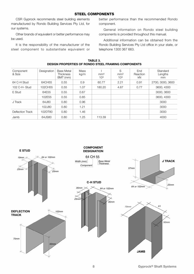
TABLE 3. DESIGN PROPERTIES OF RONDO STEEL FRAMING COMPONENTS
64 or 102mm19mm
25mm25mm
E STUD
64 CH 55Width (mm)
Component
Base MetalThickness
COMPONENT DESIGNATION
57mm
64 or 102mm25mm
J TRACK
JAMB
64 or 102mm35mm
25mm35mm
C-H STUD
102mm
75mm
50mm
DEFLECTION TRACK
CSR Gyprock recommends steel building elements manufactured by Rondo Building Services Pty Ltd, for our systems.
Other brands of equivalent or better performance may be used.
It is the responsibility of the manufacturer of the steel component to substantiate equivalent or
better performance than the recommended Rondo component.
General information on Rondo steel building components is provided throughout this manual.
Additional information can be obtained from the Rondo Building Services Pty Ltd office in your state, or telephone 1300 367 663.
Component & Size
Designation Base MetalThicknessBMT (mm)
Masskg/m
Imm4
103
Smm3
103
EndReaction
kN
StandardLengths
mm
64 C-H Stud 64CH55 0.55 0.9 60.77 2.21 0.91 2700, 3000, 3600
102 C-H- Stud 102CH55 0.55 1.07 180.20 4.67 0.77 3600, 4300
E Stud 64E55 0.55 0.67 3000, 3600
102E55 0.55 0.85 3600, 4300
J Track 64J80 0.80 0.96 3000
102J80 0.80 1.21 3000
Deflection Track 102DT80 0.80 1.46 3000
Jamb 64JS80 0.80 1.25 113.39 4000

Gyprock® Shaft Systems9
FRAMING
Steel framing shall be installed in accordance with brochure NºGYP546, Gyprock® Shaft Systems.
Shaftwal l System framing shal l consist of *64mm/102mm x ..........mm BMT C-H Studs, E Studs, J-Tracks, Jamb-Struts and Deflection Tracks.
Studs shall be designed for a maximum span/deflection ratio of *1/240 or 1/360 and shall be installed at *............mm maximum centres.
OR
Laminated Service System framing shall consist of *25mm/50mm x 0.8mm BMT galvanised steel angle.
Track fasteners shall be capable of withstanding 0.86kN single shear and 0.89kN bearing force.
PLASTERBOARD
Plasterboard lining shall comprise:
* One layer of 25mm GYPROCK Shaft Liner Panel;
PLUS/OR
........... layer(s) of ...........mm GYPROCK FYRCHEK plasterboard applied to one/both side(s) of the framing.
PLASTERBOARD FIXING
Plasterboard shall be installed in accordance with brochure NºGYP546, Gyprock® Shaft Systems.
CAULKING
All gaps and penetrations shall be caulked in accordance with brochure NºGYP546, Gyprock® Shaft Systems, using Gyprock® Fire Mastic.
JOINTING AND FINISHING
Where indicated on the drawings and/or as specified, jointing and finishing of the outer layer of GYPROCK FYRCHEK plasterboard shall be in accordance with brochure NºGYP547, Gyprock® Plasterboard Residential Installation Guide.
* Insert or select appropriate specifications.
NOTE: This information can be downloaded from the CSR Gyprock Web site: www.gyprock.com.au
Architectural Specification
SCOPE
The contractor shall furnish all materials, labour and equipment for the installation of the Gyprock® Plasterboard Shaft Systems where indicated on the drawings and/or as specified.
MATERIALS
All lining materials shall be Gyprock® plasterboard and accompanying accessories as manufactured or supplied by CSR Gyprock.
Gyprock® Plasterboard shall be manufactured to meet the dimensional requirements of AS/NZS2588 ‘Gypsum Plasterboard’.
Steel frame components shall be those manufactured by Rondo Building Services Pty Ltd (or products of equivalent or better performance).
SHAFT SYSTEMS
The contractor shal l supply and instal l the *lift shaft/stairwell/vertical duct using Gyprock® Shaft System *NºCSR............ in accordance with brochure NºGYP546, Gyprock® Shaft Systems.
The installation shall satisfy the following performance criteria.
The wall shall have a *Fire Resistance Level – /...../..... in accordance with the requirements of AS1530.4.
The wall shall be designed to resist a uniformly distributed load of *...................kPa, in accordance with BCA Specification C1.8.
Installation shall also be carried out to the level specified for an acoustic performance of *Rw...........
*Cavity infill insulation shall be .............mm Bradford...................................

Gyprock® Shaft Systems10
System SelectionSHAFTWALL SYSTEMS
Gyprock® Shaftwall Systems constructed with C-H Stud framing can be selected from Table 4.
These systems are most appropriate for lift shafts
and stairwells, and for service ducts which are outside the dimensional range of the laminated systems detailed below.
A TYPICAL SHAFTWALL SYSTEM DURING CONSTRUCTION FOR A LIFT APPLICATION
TABLE 4. MAXIMUM PERMITTED HEIGHT OF C-H STUDS (MM)
Component Designation
Stud Spacing
mm
‡ Span/
Deflection
Maximum Height of Studs – mm
FRL – /120/120 Systems CSR 971/972
FRL – /60/60 Systems CSR 970
Uniformly Distributed Load (UDL)
0.25kPa 0.35kPa 0.5kPa 0.7kPa 0.25kPa 0.35kPa
64CH55 600 600
1/240 1/360
3600* 3600*
3400 3200
3000 2900
2400 2400
3600* 3200
3200 2700
102CH55 600 600
1/240 1/360
4300* 4300
4300 3800
4000 3400
2900 2900
4300* 4000
4000 3500
* Maximum height based on fire engineering principles.‡ Span/Deflection Ratios – 1/240 for standard applications – 1/360 for walls requiring additional rigidity.
Gyprock® Shaft Systems11
LAMINATED SERVICE SYSTEMS
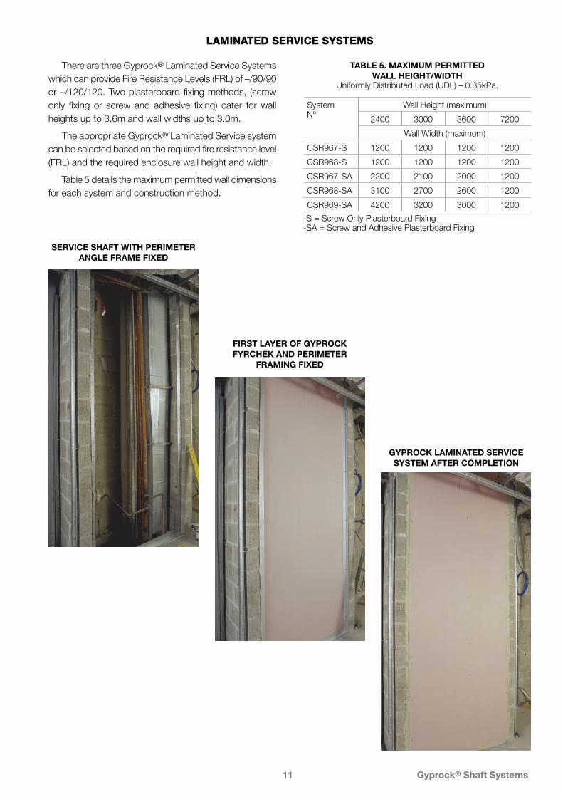
There are three Gyprock® Laminated Service Systems which can provide Fire Resistance Levels (FRL) of –/90/90 or –/120/120. Two plasterboard fixing methods, (screw only fixing or screw and adhesive fixing) cater for wall heights up to 3.6m and wall widths up to 3.0m.
The appropriate Gyprock® Laminated Service system can be selected based on the required fire resistance level (FRL) and the required enclosure wall height and width.
Table 5 details the maximum permitted wall dimensions for each system and construction method.
TABLE 5. MAXIMUM PERMITTED WALL HEIGHT/WIDTH
Uniformly Distributed Load (UDL) – 0.35kPa.
SERVICE SHAFT WITH PERIMETER ANGLE FRAME FIXED
FIRST LAYER OF GYPROCK FYRCHEK AND PERIMETER
FRAMING FIXED
GYPROCK LAMINATED SERVICE SYSTEM AFTER COMPLETION
System Nº
Wall Height (maximum)
2400 3000 3600 7200
Wall Width (maximum)
CSR967-S 1200 1200 1200 1200
CSR968-S 1200 1200 1200 1200
CSR967-SA 2200 2100 2000 1200
CSR968-SA 3100 2700 2600 1200
CSR969-SA 4200 3200 3000 1200
-S = Screw Only Plasterboard Fixing -SA = Screw and Adhesive Plasterboard Fixing

Gyprock® Shaft Systems12
Shaftwall Systems
SYSTEM SPECIFICATION TYPICAL LAYOUT ACOUSTIC OPINION
PKA-A025
• Lining material as per system table.
• 64 or 102mm C-H Metal Studs at 600mm maximum centres.
• Lining material as per system table.
FRLReport/Opinion
SYSTEM Nº
WALL LININGS STUD DEPTH mm 64 102
CAVITY INFILL (Refer to Section ‘A’) Rw / Rw+Ctr
– /60/60
BRANZ LOP 493
CSR 970
BETWEEN STUDS
• 1 x 25mm GYPROCK SHAFT LINER PANEL.
SIDE ONE
• 1 x 16mm GYPROCK FYRCHEK plasterboard.
(a) Nil 38/27 40/31
(b) 50 Glasswool Partition batts 44/33 45/36
(c) 75 Glasswool Partition batts – 46/37
(d) ASB3/TSB3 Polyester batts 42/31 45/36
(e) 60 Soundscreen™ R1.6 batts RW – 47/38
WALL THICKNESS mm 80 118
– /120/120
Test SI 1517Report/Opinion
FTO 108FTO 109CSIRO
FCO 0085
CSR 971
BETWEEN STUDS
• 1 x 25mm GYPROCK SHAFT LINER PANEL.
SIDE ONE
• 2 x 16mm GYPROCK FYRCHEK plasterboard.
(a) Nil 42/32 44/36
(b) 50 Glasswool Partition batts 48/38 49/41
(c) 75 Glasswool Partition batts – 50/42
(d) ASB3/TSB3 Polyester batts 46/36 49/41
(e) 60 Soundscreen™ R1.6 batts RW – 51/43
WALL THICKNESS mm 96 134
– /120/120
Test FR 1429Report/Opinion
BRANZ LOP 549
CSR 972
BETWEEN STUDS
• 1 x 25mm GYPROCK SHAFT LINER PANEL.
SIDE ONE
• 1 x 16mm GYPROCK FYRCHEK plasterboard.
SIDE TWO
• 1 x 16mm GYPROCK FYRCHEK plasterboard.
(a) Nil 42/31 44/35
(b) 50 Glasswool Partition batts 48/37 49/40
(c) 75 Glasswool Partition batts – 50/41
(d) ASB3/TSB3 Polyester batts 46/35 49/40
(e) 60 Soundscreen™ R1.6 batts RW – 51/42
WALL THICKNESS mm 96 134
Gyprock® Shaft Systems13
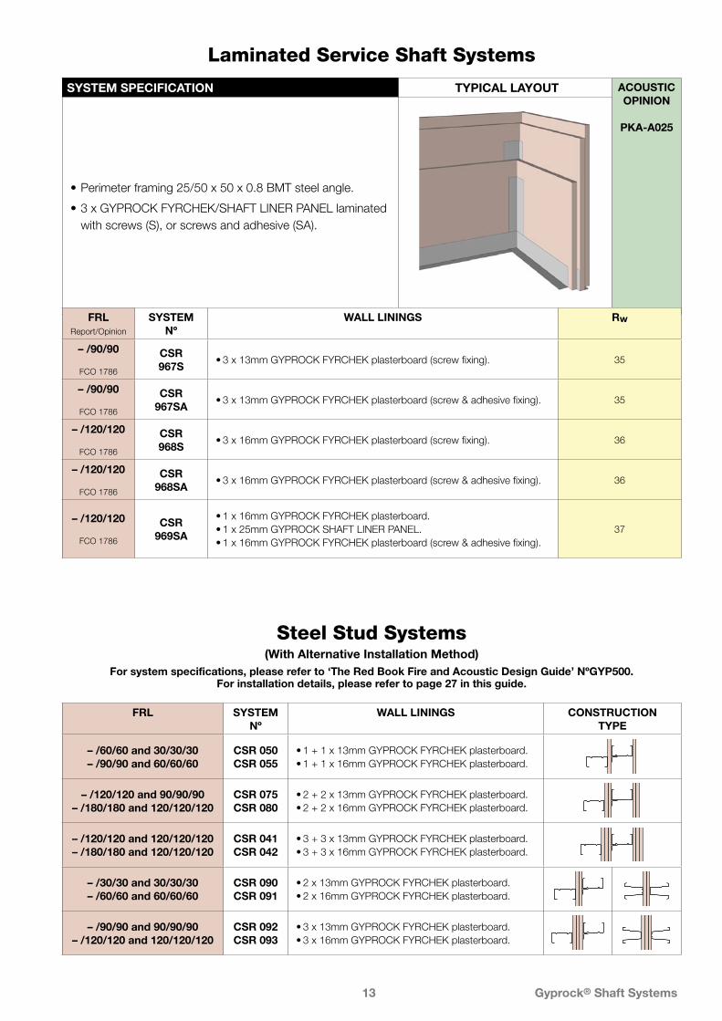
SYSTEM SPECIFICATION TYPICAL LAYOUT ACOUSTIC OPINION
PKA-A025
• Perimeter framing 25/50 x 50 x 0.8 BMT steel angle.
• 3 x GYPROCK FYRCHEK/SHAFT LINER PANEL laminated with screws (S), or screws and adhesive (SA).
Laminated Service Shaft Systems
FRLReport/Opinion
SYSTEM Nº
WALL LININGS Rw
– /90/90
FCO 1786
CSR 967S
• 3 x 13mm GYPROCK FYRCHEK plasterboard (screw fixing). 35
– /90/90
FCO 1786
CSR 967SA
• 3 x 13mm GYPROCK FYRCHEK plasterboard (screw & adhesive fixing). 35
– /120/120
FCO 1786
CSR 968S
• 3 x 16mm GYPROCK FYRCHEK plasterboard (screw fixing). 36
– /120/120
FCO 1786
CSR 968SA
• 3 x 16mm GYPROCK FYRCHEK plasterboard (screw & adhesive fixing). 36
– /120/120
FCO 1786
CSR 969SA
• 1 x 16mm GYPROCK FYRCHEK plasterboard.• 1 x 25mm GYPROCK SHAFT LINER PANEL.• 1 x 16mm GYPROCK FYRCHEK plasterboard (screw & adhesive fixing).
37
FRL SYSTEM Nº
WALL LININGS CONSTRUCTION TYPE
– /60/60 and 30/30/30– /90/90 and 60/60/60
CSR 050CSR 055
• 1 + 1 x 13mm GYPROCK FYRCHEK plasterboard.• 1 + 1 x 16mm GYPROCK FYRCHEK plasterboard.
– /120/120 and 90/90/90– /180/180 and 120/120/120
CSR 075CSR 080
• 2 + 2 x 13mm GYPROCK FYRCHEK plasterboard.• 2 + 2 x 16mm GYPROCK FYRCHEK plasterboard.
– /120/120 and 120/120/120– /180/180 and 120/120/120
CSR 041CSR 042
• 3 + 3 x 13mm GYPROCK FYRCHEK plasterboard.• 3 + 3 x 16mm GYPROCK FYRCHEK plasterboard.
– /30/30 and 30/30/30– /60/60 and 60/60/60
CSR 090CSR 091
• 2 x 13mm GYPROCK FYRCHEK plasterboard.• 2 x 16mm GYPROCK FYRCHEK plasterboard.
– /90/90 and 90/90/90– /120/120 and 120/120/120
CSR 092CSR 093
• 3 x 13mm GYPROCK FYRCHEK plasterboard.• 3 x 16mm GYPROCK FYRCHEK plasterboard.
Steel Stud Systems (With Alternative Installation Method)
For system specifications, please refer to ‘The Red Book Fire and Acoustic Design Guide’ NºGYP500.For installation details, please refer to page 27 in this guide.
Gyprock® Shaft Systems14
Shaftwall System InstallationINTRODUCTION
GYPROCK Shaftwalls are most commonly installed from one side only (known as the storey side), progressively installing the 25mm Shaft Line Panels and C-H studs before applying the finishing layer/s of 16mm GYPROCK FYRCHEK to the storey side.
Some wall systems, such as those used to enclose stairwells, require access to the shaft side of the wall for installation of a finishing layer.
SAFETY
Where walls are to be erected around open shafts ensure that adequate safety measures are taken.
FRAMING
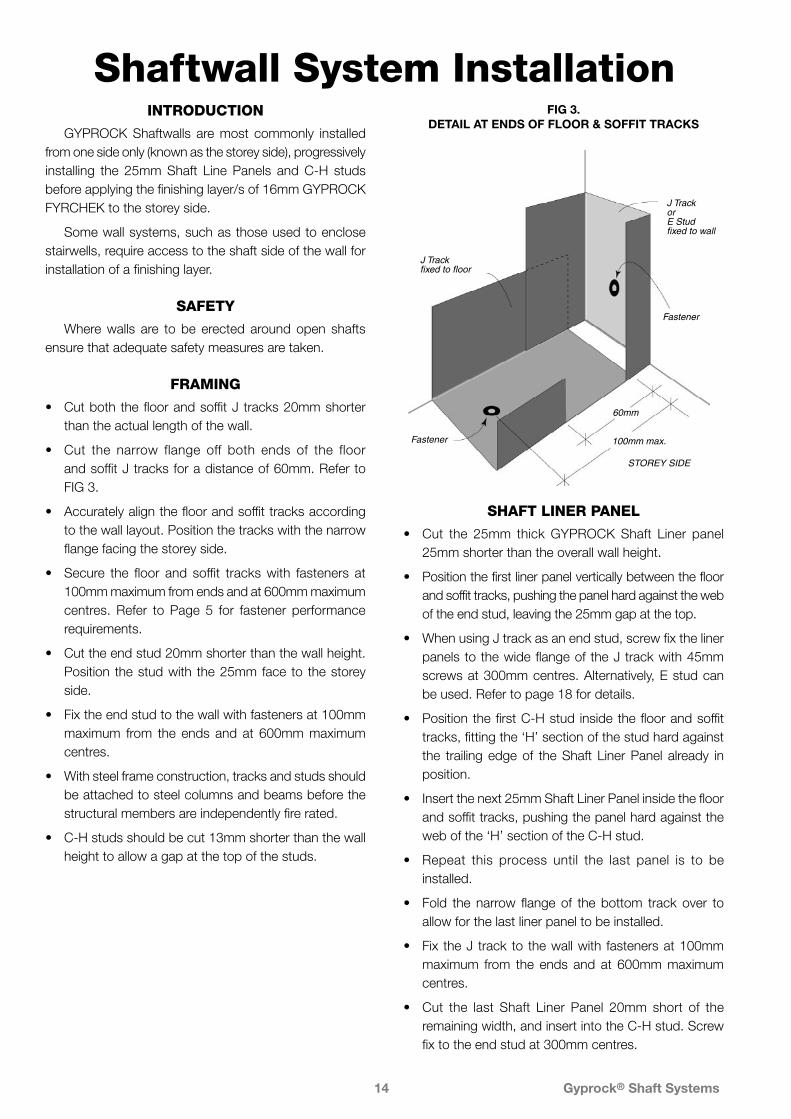
• Cut both the floor and soffit J tracks 20mm shorter than the actual length of the wall.
• Cut the narrow flange off both ends of the floor and soffit J tracks for a distance of 60mm. Refer to FIG 3.
• Accurately align the floor and soffit tracks according to the wall layout. Position the tracks with the narrow flange facing the storey side.
• Secure the floor and soffit tracks with fasteners at 100mm maximum from ends and at 600mm maximum centres. Refer to Page 5 for fastener performance requirements.
• Cut the end stud 20mm shorter than the wall height. Position the stud with the 25mm face to the storey side.
• Fix the end stud to the wall with fasteners at 100mm maximum from the ends and at 600mm maximum centres.
• With steel frame construction, tracks and studs should be attached to steel columns and beams before the structural members are independently fire rated.
• C-H studs should be cut 13mm shorter than the wall height to allow a gap at the top of the studs.
SHAFT LINER PANEL
• Cut the 25mm thick GYPROCK Shaft Liner panel 25mm shorter than the overall wall height.
• Position the first liner panel vertically between the floor and soffit tracks, pushing the panel hard against the web of the end stud, leaving the 25mm gap at the top.
• When using J track as an end stud, screw fix the liner panels to the wide flange of the J track with 45mm screws at 300mm centres. Alternatively, E stud can be used. Refer to page 18 for details.
• Position the first C-H stud inside the floor and soffit tracks, fitting the ‘H’ section of the stud hard against the trailing edge of the Shaft Liner Panel already in position.
• Insert the next 25mm Shaft Liner Panel inside the floor and soffit tracks, pushing the panel hard against the web of the ‘H’ section of the C-H stud.
• Repeat this process until the last panel is to be installed.
• Fold the narrow flange of the bottom track over to allow for the last liner panel to be installed.
• Fix the J track to the wall with fasteners at 100mm maximum from the ends and at 600mm maximum centres.
• Cut the last Shaft Liner Panel 20mm short of the remaining width, and insert into the C-H stud. Screw fix to the end stud at 300mm centres.
SHAFT SIDE
J Track fixed to floor
100mm max.
60mm
Fastener
Fastener
J TrackorE Studfixed to wall
STOREY SIDE
FIG 3. DETAIL AT ENDS OF FLOOR & SOFFIT TRACKS
Gyprock® Shaft Systems15
1
2
3
4
56
7
89
Floor Track
Soffit Track
End Stud
End Stud
C-H Stud
GYPROCKShaft Liner Panel
Fold down narrow flange to allow placement of last Shaft Liner Panel
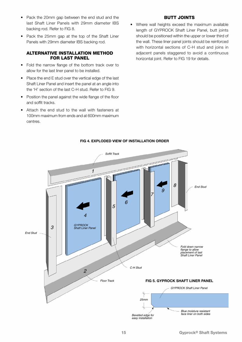
FIG 5. GYPROCK SHAFT LINER PANEL
25mm
Blue moisture resistantface liner on both sides
GYPROCK Shaft Liner Panel
Bevelled edge foreasy installation
• Pack the 20mm gap between the end stud and the last Shaft Liner Panels with 29mm diameter IBS backing rod. Refer to FIG 8.
• Pack the 25mm gap at the top of the Shaft Liner Panels with 29mm diameter IBS backing rod.
ALTERNATIVE INSTALLATION METHOD FOR LAST PANEL
• Fold the narrow flange of the bottom track over to allow for the last liner panel to be installed.
• Place the end E stud over the vertical edge of the last Shaft Liner Panel and insert the panel at an angle into the ‘H’ section of the last C-H stud. Refer to FIG 9.
• Position the panel against the wide flange of the floor and soffit tracks.
• Attach the end stud to the wall with fasteners at 100mm maximum from ends and at 600mm maximum centres.
BUTT JOINTS
• Where wall heights exceed the maximum available length of GYPROCK Shaft Liner Panel, butt joints should be positioned within the upper or lower third of the wall. These liner panel joints should be reinforced with horizontal sections of C-H stud and joins in adjacent panels staggered to avoid a continuous horizontal joint. Refer to FIG 19 for details.
FIG 4. EXPLODED VIEW OF INSTALLATION ORDER

Gyprock® Shaft Systems16
J Track
C-H Studs
Staggered Joints
25mm GYPROCKShaft Liner Panels
J Track
2nd layer of GYPROCK FYRCHECK plasterboard
1st layer ofGYPROCK FYRCHECKplasterboard
Caulk all perimeter gaps with Gyprock Fire Mastic to achieve stated fire and/or acoustic performance
300mmmax.
300mmmax.
600mmmax.
600mmmax.
300mmmax.
FIG 6. INSTALLATION DETAIL FOR SHAFTWALL SYSTEMS
NOTES ON FIXING FYRCHEK PLASTERBOARD
• Offset joints in adjacent layers or layers on opposite sides of the wall by one stud.
• Cut sheets as necessary to provide 6-10mm clearance at the head and ends of the wall, and a 6mm gap at the bottom of the outer layer sheets.
• Do not fix sheets to the top and bottom tracks except for walls enclosing lifts.
• If butt joints are required, they must be staggered by 600mm min. between layers, between adjacent sheets and on opposite sides of the wall. Joints must be either backed by nogging and screw fixed at 200mm max. centres, or fixed with laminating screws at 200mm max. centres.
• Place edge fasteners at 10 to 16mm from sheet edge.
FIXING PROCEDURE DOUBLE LAYER SYSTEMS
For fastener specifications refer to FIG 6.
First Layer
• Apply sheets vertically with paper bound edges parallel with studs and with recess joints centred on stud flanges.
• Press the sheet firmly against the studs and screw fix at 100mm maximum from top and bottom of sheet,
and at 600mm maximum centres along recessed edges, at all angles and around openings.
Second Layer
• Cut the first sheet to half width so that joints in the second layer do not align with joints in the first layer.
• Apply sheets vertically, leaving a 6mm gap between the bottom of the sheet and the floor, at the head and ends of the wall and screw fix at 100mm maximum from top and bottom of sheet, and at 300mm maximum centres to all studs.
• Screw fix at all angles and around openings at 300mm maximum centres.
SINGLE LAYER SYSTEMS
• Fix single layer systems as per the details for the second layer of double layer systems.
Single Layer Systems Lined Both Sides
• Install the plasterboard to the first side as per the procedure detailed for the second layer. Do not fix sheets to intermediate studs at this time.
• Start the second side with a half width sheet so that joints on opposite sides of the wall are located on different studs.
• Screw fix this and subsequent full width sheets to all studs at 100mm maximum from top and bottom of sheet, and at 300mm maximum centres to all studs.
IMPORTANT
Walls enclosing lift shafts MUST have both layers of GYPROCK FYRCHEK separately fastened to the top and bottom J tracks with screws at 300mm maximum spacings.
FIRE RATEDFYRCHEK Fixing Specifications1st Layer2nd layer
Gyprock 25‘S’ ScrewsGyprock 40‘S’ Screws
1st Layer Fixing & SpacingRecessed Edges & Field
#6-18 x 25mm, bugle head screws at 600mm max. centres on studs
2nd Layer Fixing & SpacingRecessed Edges & Field
#6-18 x 40mm, bugle head screws at 300mm max. centres on studs
Butt Joints Laminating screws at 200mm max. centres
Corners & Openings
#6-18 x 40mm, bugle head screws at 300mm max. centres

Gyprock® Shaft Systems17
JUNCTIONS WITH MASONRY WALLS
E Stud Shaft Side
Gyprock Fire Mastic
2 Layers 16mmGYPROCK FYRCHEK
25mm GYPROCKShaft Liner Panel
6mm
FIG 9.-E-STUD DETAIL
2 Layers 16mmGYPROCK FYRCHEK
J Track
25mm GYPROCKShaft Liner Panel
6mm
Gyprock Fire Mastic
SHAFT SIDE
FIG 7. J-TRACK DETAIL
S H A F T S ID EJ Track
25mm GyprockShaft Liner
IBS Rod 29mm dia.
2 Layers 16mmGYPROCK FYRCHEK
Gyprock Fire Mastic6mm
FIG 8. J-TRACK WITH IBS™ ROD
Wall Junction Details
FIG 10. JUNCTION WITH C-H STUD WALL
C-H Stud
2 Layers 16mmGYPROCK FYRCHEK STOREY SIDE
J Track
FIG 11. JUNCTION WITH C-H STUD WALL
GYPROCK FYRCHEKplasterboard
25 x 38mmSteel angle
J Track
GYPROCK Shaft Liner Panel
SHAFT SIDE
• Return to the first side and screw fix plasterboard to intermediate studs at 100mm maximum from top and bottom of sheet, but not through tracks, (see notes) and at 300mm maximum centres.
Sealants
Fill all perimeter gaps with Gyprock® Fire Mastic to a minimum depth of 16mm.
Jointing
Fire rated shaft systems must be jointed with perforated paper tape and standard Gyprock® jointing techniques in accordance with brochure NºGYP547, Gyprock® Plasterboard Residential Installation Guide.
Tape and set face layer joints of GYPROCK FYRCHEK plasterboard only.
Angles formed between adjacent wall surfaces must also be taped and set.
Gyprock® Shaft Systems18
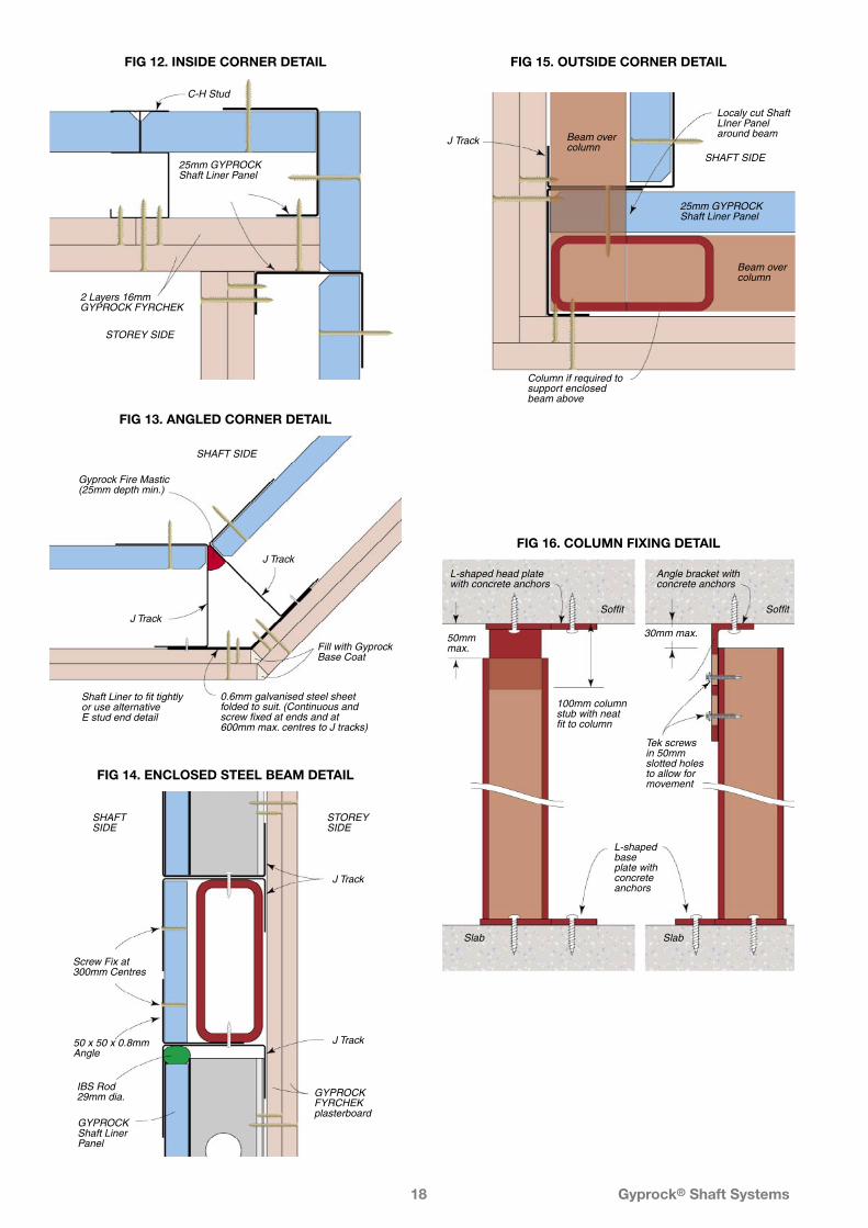
FIG 12. INSIDE CORNER DETAIL
J Track
C-H Stud
2 Layers 16mmGYPROCK FYRCHEK
25mm GYPROCKShaft Liner Panel
STOREY SIDE
FIG 13. ANGLED CORNER DETAIL
J Track
J Track
SHAFT SIDE
Gyprock Fire Mastic (25mm depth min.)
Shaft Liner to fit tightlyor use alternativeE stud end detail
0.6mm galvanised steel sheet folded to suit. (Continuous and screw fixed at ends and at 600mm max. centres to J tracks)
Fill with Gyprock Base Coat
FIG 14. ENCLOSED STEEL BEAM DETAIL
IBS Rod29mm dia.
Screw Fix at300mm Centres
J Track
J Track
SHAFTSIDE
STOREYSIDE
GYPROCK FYRCHEK plasterboard
GYPROCK Shaft Liner Panel
50 x 50 x 0.8mm Angle
FIG 15. OUTSIDE CORNER DETAIL
SHAFT SIDE
Beam overcolumn
Beam overcolumn
25mm GYPROCKShaft Liner Panel
J Track
Column if required to support enclosed beam above
Localy cut Shaft LIner Panel around beam
FIG 16. COLUMN FIXING DETAIL
50mm max.
Soffit
Slab
Soffit
Slab
100mm columnstub with neatfit to column
L-shaped base plate with concrete anchors
L-shaped head plate with concrete anchors
Angle bracket with concrete anchors
30mm max.
Tek screws in 50mm slotted holes to allow for movement
Gyprock® Shaft Systems19
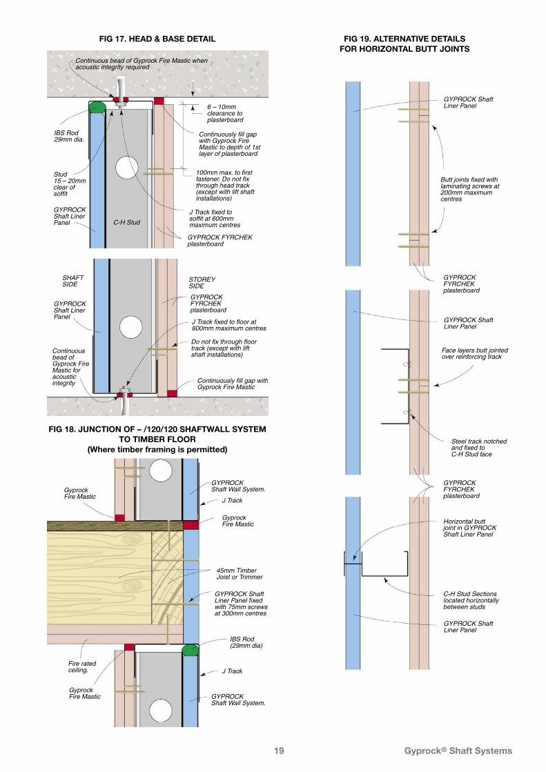
FIG 18. JUNCTION OF – /120/120 SHAFTWALL SYSTEM TO TIMBER FLOOR
(Where timber framing is permitted)
GYPROCK Shaft Liner Panel fixed with 75mm screws at 300mm centres
IBS Rod (29mm dia)
45mm Timber Joist or Trimmer
GyprockFire Mastic
GyprockFire Mastic
J Track
J Track
GyprockFire Mastic
Fire rated ceiling.
GYPROCKShaft Wall System.
GYPROCKShaft Wall System.
FIG 17. HEAD & BASE DETAIL
6 – 10mm clearance to plasterboard
Continuously fill gap with Gyprock Fire Mastic to depth of 1st layer of plasterboard
J Track fixed to soffit at 600mm maximum centres
GYPROCK FYRCHEK plasterboard
GYPROCK Shaft Liner Panel
100mm max. to first fastener. Do not fix through head track (except with lift shaft installations)
Stud15 – 20mmclear of soffit
Continuous bead of Gyprock Fire Mastic when acoustic integrity required
IBS Rod 29mm dia.
C-H Stud
FIG 19. ALTERNATIVE DETAILS FOR HORIZONTAL BUTT JOINTS
Face layers butt jointedover reinforcing track
Steel track notchedand fixed toC-H Stud face
Horizontal buttjoint in GYPROCK Shaft Liner Panel
GYPROCK FYRCHEKplasterboard
C-H Stud Sectionslocated horizontallybetween studs
GYPROCK FYRCHEKplasterboard
Butt joints fixed with laminating screws at 200mm maximum centres
GYPROCK Shaft Liner Panel
GYPROCK Shaft Liner Panel
GYPROCK Shaft Liner Panel
GYPROCK FYRCHEK plasterboard
STOREY SIDE
SHAFT SIDE
Continuously fill gap with Gyprock Fire Mastic
J Track fixed to floor at 600mm maximum centres
Continuous bead of Gyprock Fire Mastic for acoustic integrity
GYPROCK Shaft Liner Panel
Do not fix through floor track (except with lift shaft installations)

Gyprock® Shaft Systems20
WALL JUNCTIONS WITH STRUCTURAL STEEL MEMBERS
FIG 20. WALL JUNCTION AT UNIVERSAL COLUMN
SHAFT SIDE
Sprayed Fire Resistant Material
J Track
GYPROCK Shaft Liner Panel
External CornerBead and set over GYPROCK
FYRCHEKplasterboard
FIG 24. WALL HEAD CONNECTION TO STEEL BEAM
12mm min.
Deflection orJ Track
STOREYSIDE
SHAFTSIDE
Sprayed Fire Resistant Material
GYPROCK Shaft Liner Panel
GYPROCKFYRCHEKplasterboard
IBS Rod 29mm dia.
C-HStud
Gyprock Fire Mastic6mm min. / 20mm max. height
FIG 25. WALL HEAD CONNECTION TO STEEL BEAM
203mm max.12mm min.
50mm min.
Gyprock Fire Mastic6mm min./ 20mm max. height
Deflection orJ Track
STOREYSIDE
SHAFTSIDE
Sprayed Fire Resistant Material
GYPROCKFYRCHEKplasterboard
IBS Rod 29mm dia.
GYPROCK Shaft Liner Panel
C-HStud
FIG 22. WALL JUNCTION AT UNIVERSAL COLUMN
SHAFT SIDESHAFT SIDE
Sprayed Fire Resistant Material
GYPROCK FYRCHEK plasterboard
GYPROCK Shaft Liner Panel
FIG 23. WALL BYPASSING UNIVERSAL COLUMN ALTERNATIVE DETAIL
SHAFT SIDESHAFT SIDE
Sprayed Fire Resistant Material
GYPROCK FYRCHEK plasterboard
GYPROCK Shaft Liner Panel
Galvanised Steel Angle fixed to column and J Track
FIG 21. WALL JUNCTION AT UNIVERSAL COLUMN
Sprayed Fire Resistant Material
J TrackExternal CornerBead and set over GYPROCK
FYRCHEKplasterboard
GYPROCK Shaft Liner Panel
Galvanised Steel Angle fixed to column and J Track
Gyprock® Shaft Systems21
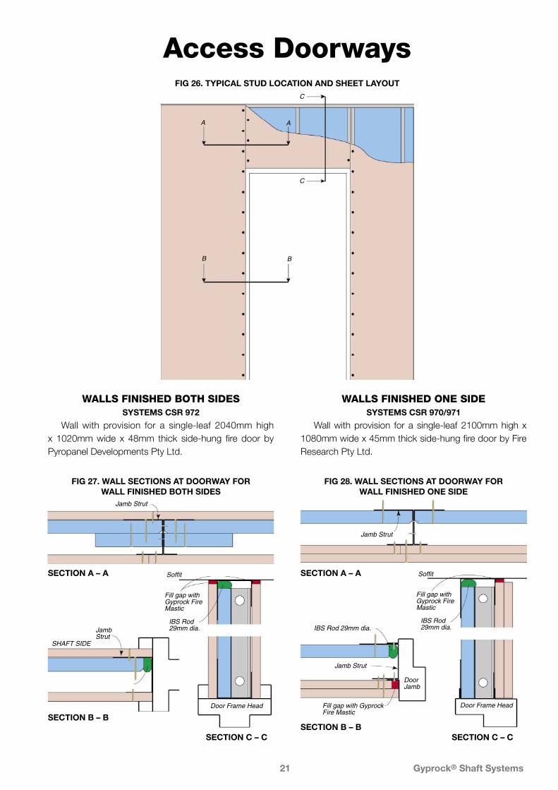
FIG 27. WALL SECTIONS AT DOORWAY FOR WALL FINISHED BOTH SIDES
FIG 28. WALL SECTIONS AT DOORWAY FOR WALL FINISHED ONE SIDE
Access Doorways
WALLS FINISHED BOTH SIDESSYSTEMS CSR 972
Wall with provision for a single-leaf 2040mm high x 1020mm wide x 48mm thick side-hung fire door by Pyropanel Developments Pty Ltd.
WALLS FINISHED ONE SIDESYSTEMS CSR 970/971
Wall with provision for a single-leaf 2100mm high x 1080mm wide x 45mm thick side-hung fire door by Fire Research Pty Ltd.
A A
B B
C
C
FIG 26. TYPICAL STUD LOCATION AND SHEET LAYOUT
Jamb Strut
SECTION A – A
Jamb Strut
SECTION A – A
IBS Rod 29mm dia.
DoorJamb
Jamb Strut
SHAFT SIDE
SECTION B – B
IBS Rod 29mm dia.
Door Jamb
Fill gap with Gyprock Fire Mastic
Jamb Strut
SECTION B – B
IBS Rod 29mm dia.
Fill gap with Gyprock Fire Mastic
Door Frame Head
Soffit
SECTION C – C
IBS Rod 29mm dia.
Fill gap with Gyprock Fire Mastic
Door Frame Head
Soffit
SECTION C – C
Gyprock® Shaft Systems22
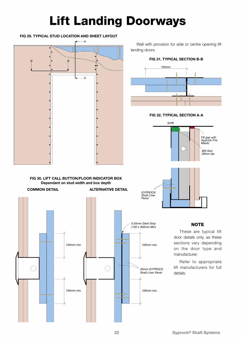
Lift Landing DoorwaysA
A
B B
FIG 29. TYPICAL STUD LOCATION AND SHEET LAYOUT
FIG 32. TYPICAL SECTION A-A
FIG 31. TYPICAL SECTION B-B
150mm
FIG 30. LIFT CALL BUTTON/FLOOR INDICATOR BOXDependant on stud width and box depth
100mm min.
100mm min.
0.55mm Steel Strip(150 x 300mm Min)
25mm GYPROCKShaft Liner Panel
100mm min.
100mm min.
Fill gap with Gyprock Fire Mastic
IBS Rod 29mm dia.
Soffit
GYPROCK Shaft Liner Panel
Wall with provision for side or centre opening lift landing doors.
ALTERNATIVE DETAILCOMMON DETAIL
NOTE
These are typical lift door details only, as these sections vary depending on the door type and manufacturer.
Refer to appropriate lift manufacturers for full details.
Gyprock® Shaft Systems23
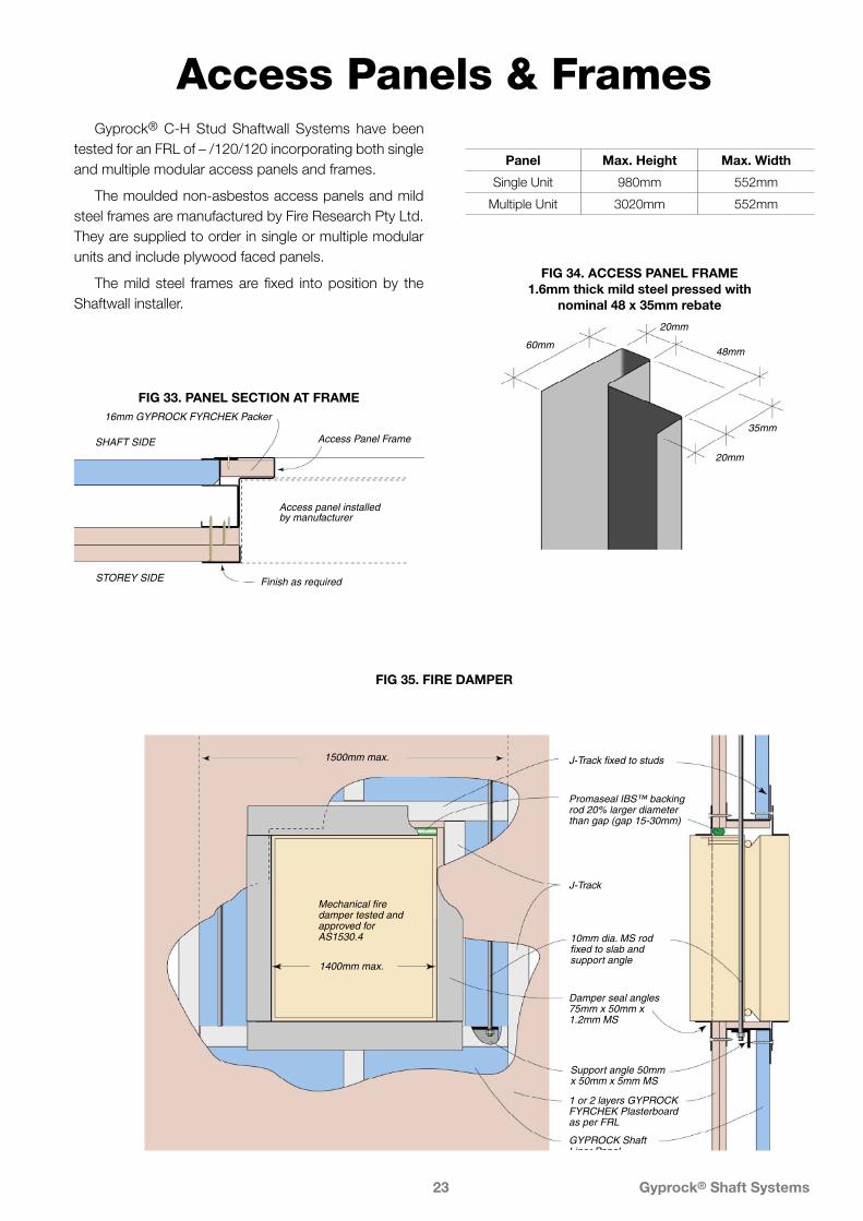
Access Panels & FramesGyprock® C-H Stud Shaftwall Systems have been
tested for an FRL of – /120/120 incorporating both single and multiple modular access panels and frames.
The moulded non-asbestos access panels and mild steel frames are manufactured by Fire Research Pty Ltd. They are supplied to order in single or multiple modular units and include plywood faced panels.
The mild steel frames are fixed into position by the Shaftwall installer.
20mm
35mm
48mm
20mm
60mm
FIG 34. ACCESS PANEL FRAME1.6mm thick mild steel pressed with
nominal 48 x 35mm rebate
Panel Max. Height Max. Width
Single Unit 980mm 552mm
Multiple Unit 3020mm 552mm
SHAFT SIDE
16mm GYPROCK FYRCHEK Packer
Access Panel Frame
Access panel installedby manufacturer
Finish as requiredSTOREY SIDE
FIG 33. PANEL SECTION AT FRAME
Promaseal IBS™ backing rod 20% larger diameter than gap (gap 15-30mm)
1 or 2 layers GYPROCK FYRCHEK Plasterboard as per FRL
GYPROCK Shaft Liner Panel
Support angle 50mm x 50mm x 5mm MS
10mm dia. MS rod fixed to slab and support angle
Mechanical fire damper tested and approved for AS1530.4
J-Track fixed to studs
J-Track
Damper seal angles 75mm x 50mm x 1.2mm MS
1400mm max.
1500mm max.
FIG 35. FIRE DAMPER
Gyprock® Shaft Systems24
Laminated Service System
Installation
Caulk all perimeter gaps as detailed in FIG 37, 38 and 40. Apply external corner bead and set corners where appropriate.
PLASTERBOARD FIXING
SCREW AND ADHESIVE INSTALLATION
NOTE: Sheet joints must be offset a minimum or 300mm from joints in the adjacent layers. The minimum width of any sheet is 300mm. Determine the appropriate sheet widths to be installed before installing the first layer.
Install the first layer as detailed for the screw only system. Prop intermediate sheets or temporarily screw to the top and bottom steel angles. Remove temporary screws before fixing the second layer.
Install additional steel angles around the enclosure at the top, bottom and corners, and fix as for the original framing. Refer to FIG 37, 38, 39 and 40 for details.
Mix sufficient Gyprock® Base Coat 100 or Gyprock® Cornice Cement to cover the wall surface. Cut the second layer sheets 20mm short of the frame height and lay them face down on a flat surface.
Using a 5mm notched trowel, cover the entire back with the chosen adhesive.
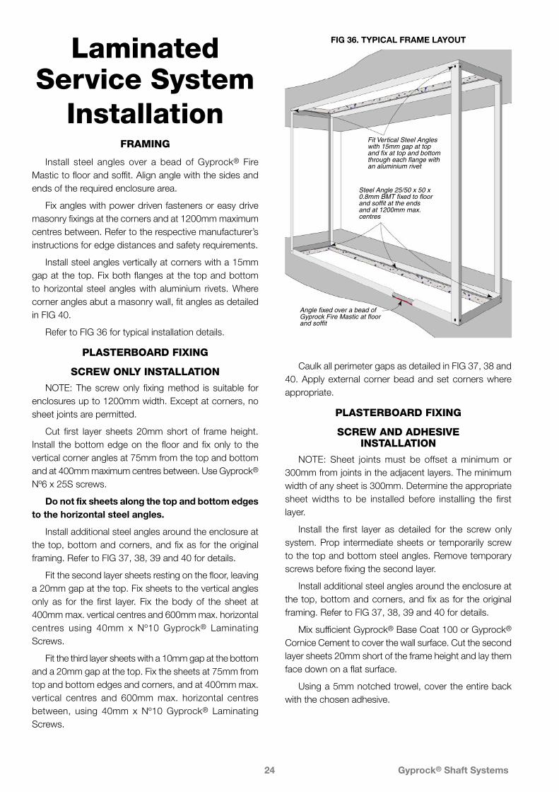
Steel Angle 25/50 x 50 x 0.8mm BMT fixed to floor and soffit at the ends and at 1200mm max. centres
Fit Vertical Steel Angles with 15mm gap at top and fix at top and bottom through each flange with an aluminium rivet
Angle fixed over a bead of Gyprock Fire Mastic at floor and soffit
FIG 36. TYPICAL FRAME LAYOUT
FRAMING
Install steel angles over a bead of Gyprock® Fire Mastic to floor and soffit. Align angle with the sides and ends of the required enclosure area.
Fix angles with power driven fasteners or easy drive masonry fixings at the corners and at 1200mm maximum centres between. Refer to the respective manufacturer’s instructions for edge distances and safety requirements.
Install steel angles vertically at corners with a 15mm gap at the top. Fix both flanges at the top and bottom to horizontal steel angles with aluminium rivets. Where corner angles abut a masonry wall, fit angles as detailed in FIG 40.
Refer to FIG 36 for typical installation details.
PLASTERBOARD FIXING
SCREW ONLY INSTALLATION
NOTE: The screw only fixing method is suitable for enclosures up to 1200mm width. Except at corners, no sheet joints are permitted.
Cut first layer sheets 20mm short of frame height. Install the bottom edge on the floor and fix only to the vertical corner angles at 75mm from the top and bottom and at 400mm maximum centres between. Use Gyprock® Nº6 x 25S screws.
Do not fix sheets along the top and bottom edges to the horizontal steel angles.
Install additional steel angles around the enclosure at the top, bottom and corners, and fix as for the original framing. Refer to FIG 37, 38, 39 and 40 for details.
Fit the second layer sheets resting on the floor, leaving a 20mm gap at the top. Fix sheets to the vertical angles only as for the first layer. Fix the body of the sheet at 400mm max. vertical centres and 600mm max. horizontal centres using 40mm x Nº10 Gyprock® Laminating Screws.
Fit the third layer sheets with a 10mm gap at the bottom and a 20mm gap at the top. Fix the sheets at 75mm from top and bottom edges and corners, and at 400mm max. vertical centres and 600mm max. horizontal centres between, using 40mm x Nº10 Gyprock® Laminating Screws.

Gyprock® Shaft Systems25
Fit the second layer sheets immediately, leaving a 20mm gap at the top. Screw fix as detailed for the second layer of the fastener only system.
Apply adhesive to the back of the third layer sheets as previously detailed and install with a 10mm gap at the bottom and a 20mm gap at the top. Screw fix as detailed for the third layer of the screw only system.
Caulk all perimeter gaps as detailed in FIG 37, 38 and 40. Apply external corner bead and set corners and joints where appropriate.
25/50 x 50 x 0.8mm BMT Steel Angle
Gyprock Fire Mastic
Gyprock Fire Mastic
22mm IBS™ Rod
20mm
Soffit
Floor
10mm
75mm
ServiceShaftSide
FIG 38. HEAD & BASE DETAIL
25/50 x 50 x 0.8mm BMT Steel Angle
External Corner Setting Bead if required
ServiceShaftSide
FIG 39. VERTICAL CORNERPlan View
Steel Angle internal framing
Steel angle frame installed over first layer of plasterboard at floor, soffit and vertical corners
Fix 1st layer to vertical steel angles only
Apply adhesive and screw fix 2nd layer to vertical steel angles with 25/45mm Gyprock screws. Fix body with laminating screws at 600mm max. horizontal x 400mm max. vertical centres
Apply adhesive and screw fix body of 3rd layer with laminating screws only at 600mm max. horizontal x 400mm max. vertical centres
75mm 600mm max.400mmmax.
400mmmax.
75mm
Gyprock Fire Mastic at head of 2nd layer
Gyprock Fire Mastic at base of 3rd layer
IBS Backing Rod at head of 1st layer
FIG 37. TYPICAL FIXING – SCREW AND ADHESIVE METHOD
Gyprock® Shaft Systems26
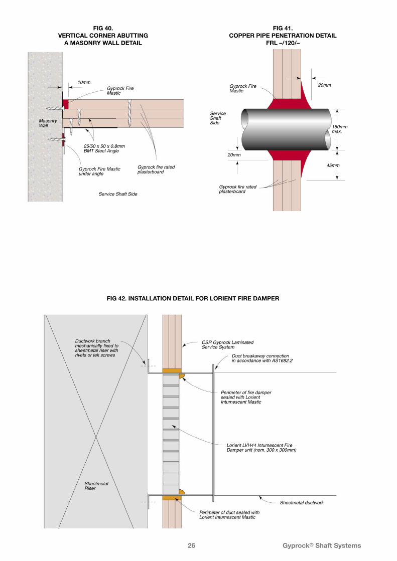
25/50 x 50 x 0.8mm BMT Steel Angle
Service Shaft Side
MasonryWall
10mmGyprock Fire Mastic
Gyprock Fire Mastic under angle
Gyprock fire rated plasterboard
FIG 40. VERTICAL CORNER ABUTTING
A MASONRY WALL DETAIL
45mm
20mm
20mmGyprock Fire Mastic
150mmmax.
ServiceShaftSide
Gyprock fire rated plasterboard
FIG 41. COPPER PIPE PENETRATION DETAIL
FRL –/120/–
Perimeter of fire damper sealed with Lorient Intumescent Mastic
Lorient LVH44 Intumescent Fire Damper unit (nom. 300 x 300mm)
Perimeter of duct sealed with Lorient Intumescent Mastic
Duct breakaway connection in accordance with AS1682.2
SheetmetalRiser
Ductwork branch mechanically fixed to sheetmetal riser with rivets or tek screws
CSR Gyprock Laminated Service System
Sheetmetal ductwork
FIG 42. INSTALLATION DETAIL FOR LORIENT FIRE DAMPER
Gyprock® Shaft Systems27
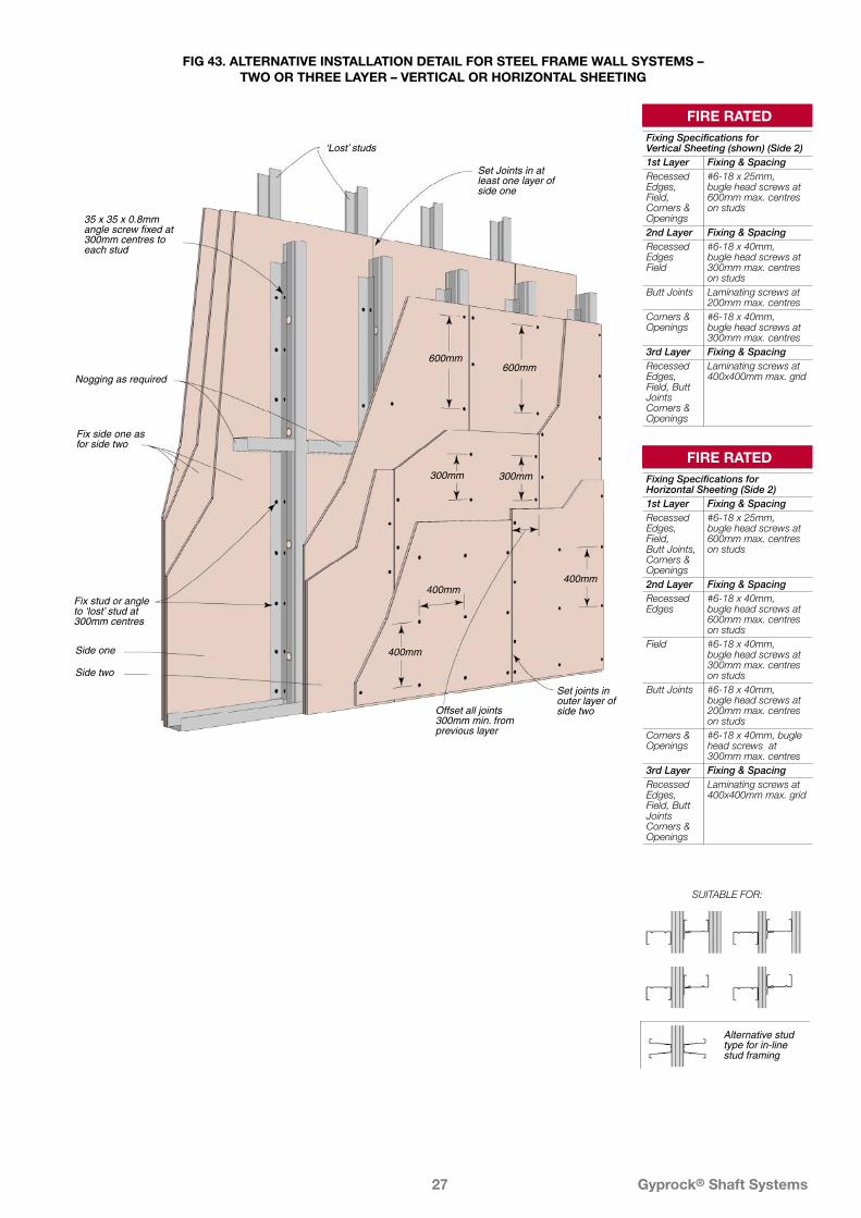
35 x 35 x 0.8mm angle screw fixed at 300mm centres to each stud
Nogging as required
Side one
Fix side one as for side two
Set joints in outer layer of side two
Set Joints in at least one layer of side one
‘Lost’ studs
Offset all joints 300mm min. from previous layer
Fix stud or angle to ‘lost’ stud at 300mm centres
600mm600mm
300mm 300mm
400mm
400mm400mm
Side two
FIG 43. ALTERNATIVE INSTALLATION DETAIL FOR STEEL FRAME WALL SYSTEMS – TWO OR THREE LAYER – VERTICAL OR HORIZONTAL SHEETING
SUITABLE FOR:
Alternative stud type for in-line stud framing
FIRE RATEDFixing Specifications for Vertical Sheeting (shown) (Side 2)1st Layer Fixing & SpacingRecessed Edges, Field, Corners & Openings
#6-18 x 25mm, bugle head screws at 600mm max. centres on studs
2nd Layer Fixing & SpacingRecessed Edges Field
#6-18 x 40mm, bugle head screws at 300mm max. centres on studs
Butt Joints Laminating screws at 200mm max. centres
Corners & Openings
#6-18 x 40mm, bugle head screws at 300mm max. centres
3rd Layer Fixing & SpacingRecessed Edges, Field, Butt Joints Corners & Openings
Laminating screws at 400x400mm max. grid
FIRE RATEDFixing Specifications for Horizontal Sheeting (Side 2)1st Layer Fixing & SpacingRecessed Edges, Field, Butt Joints, Corners & Openings
#6-18 x 25mm, bugle head screws at 600mm max. centres on studs
2nd Layer Fixing & SpacingRecessed Edges
#6-18 x 40mm, bugle head screws at 600mm max. centres on studs
Field #6-18 x 40mm, bugle head screws at 300mm max. centres on studs
Butt Joints #6-18 x 40mm, bugle head screws at 200mm max. centres on studs
Corners & Openings
#6-18 x 40mm, bugle head screws at 300mm max. centres
3rd Layer Fixing & SpacingRecessed Edges, Field, Butt Joints Corners & Openings
Laminating screws at 400x400mm max. grid

28
CSR Building Products Limited A.B.N. 55 008 631 356.The following are trade marks of CSR Limited and are under license: CSR™, Gyprock®, Fyrchek™, FyrchekMR™, designLINK®. © CSR Gyprock, Publication GYP546.BMS8239.0605
Health & SafetyInformation on any known health risks of our
products and how to handle them safely is on their package and/or the documentation accompanying them.
Additional information is listed in the Material Safety Data sheet.
To obtain a copy, telephone 13 17 44, or visit www.gyprock.com.au
GuaranteeCSR Limited guarantees its Gyprock® products to
be free of defects in materials and manufacture.
If a CSR product does not meet our standard, we will, at our option, replace or repair it, supply an equivalent product, or pay for doing one of these.
CSR recommends that only products, components and systems recommended by it be used. If this is not done, CSR will need to be satisfied that any defect in its product is attributable to our failure to meet our standard (and not another cause) before this guarantee applies.
This guarantee excludes all other guarantees and liability for damage or loss in connection with defects in CSR's product, other than those imposed by legislation.
CSR Gyprock Web Sitewww.gyprock.com.au
CSR Gyprock Sales SupportTelephone: 13 17 44
Facsimile: 1800 646 364
CSR designLINK® Technical Support ServiceTelephone: 1800 621 117
New South Wales and ACT376 Victoria Street, Wetherill Park NSW 2164
Queensland768 Boundary Road, Coopers Plains QLD 4108
Victoria277 Whitehall Street, Yarraville VIC 3013
South AustraliaLot 100 Sharp Court, Mawson Lakes SA 5095
Western Australia21 Sheffield Road, Welshpool WA 6106
TasmaniaPO Box 61, Glenorchy TAS 7010
Northern TerritoryCnr Stuart Hwy & Angliss Rd, Berrimah NT 0828
New ZealandTelephone: 0800 277 123
GYP546 June 2005