lift station and force main guidelines
TRANSCRIPT
CITY OF RIVERSIDE PUBLIC WORKS DEPARTMENT
ENGINEERING DIVISION 3900 MAIN STREET
RIVERSIDE, CALIFORNIA 92522 (951) 826-5341
CITY OF RIVERSIDE SEWAGE LIFT STATION AND FORCE MAIN GUIDELINES
SEPTEMBER, 2012
Prepared by
KRIEGER & STEWART, INCORPORATED ENGINEERING CONSULTANTS
3602 UNIVERSITY AVENUE RIVERSIDE, CALIFORNIA 92501
(951) 684-6900
WGH/cam/blt Reports/476-16P2-SLS GL

TABLE OF CONTENTS
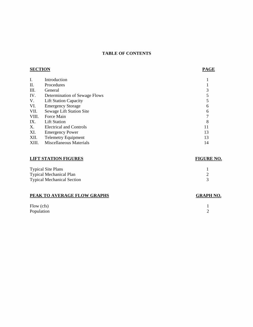
TABLE OF CONTENTS
SECTION PAGE I. Introduction 1 II. Procedures 1 III. General 3 IV. Determination of Sewage Flows 5 V. Lift Station Capacity 5 VI. Emergency Storage 6 VII. Sewage Lift Station Site 6 VIII. Force Main 7 IX. Lift Station 8 X. Electrical and Controls 11 XI. Emergency Power 13 XII. Telemetry Equipment 13 XIII. Miscellaneous Materials 14 LIFT STATION FIGURES FIGURE NO. Typical Site Plans 1 Typical Mechanical Plan 2 Typical Mechanical Section 3 PEAK TO AVERAGE FLOW GRAPHS GRAPH NO. Flow (cfs) 1 Population 2

GUIDELINES

1
CITY OF RIVERSIDE SEWAGE LIFT STATION AND FORCE MAIN GUIDELINES
I. Introduction Sewage collection within the City of Riverside (City) service area shall be provided by the
construction of gravity sewers, except where it is demonstrated unfeasible and pumping is required. If a sewage lift station is proposed, it shall be the developer's responsibility to provide the services of a licensed civil engineer to provide analysis that demonstrates to the City that a sewage lift station is the most feasible method for sewage conveyance. Said analysis shall consider constructing and maintaining a lift station over a 20-year period versus obtaining right-of-way and constructing a gravity system. If the analysis shows that a lift station is the only feasible alternative, the following guidelines shall be used in its design.
These guidelines present basic concepts and general criteria for sewage lift station facilities with
capacities not exceeding 500 gpm. Each lift station shall be reviewed and approved by the City from concept through design, construction, and startup. Lift Station Figures 1 through 3 are provided to present general lift station arrangement and components of construction. The City reserves the right to modify and supplement these guidelines and require additional facilities, depending upon the specific project location, limitations, and changes in government regulations and standards.
II. Procedures
Prior to the City's approval and acceptance of a sewage lift station, developer and developer's engineer shall comply with the following requirements:
A. Developer's engineer shall acquire and review these guidelines. B. Developer and engineer shall request a concept meeting with City staff to demonstrate
the need for a sewage lift station and to review requirements, guidelines, criteria, right-of-way, and location of specific project facilities. City will provide list of preferred equipment and materials.
C. Developer shall submit all documentation requested by the City in order to demonstrate
the need for a sewage lift station, including the following:
1. Complete calculations for sewage flows within the entire drainage area tributary to the lift station. (See Section IV, herein).
2. Preliminary drawings showing planned gravity collection system within the lift
station drainage area, including point(s) of connection to existing or future gravity interceptor sewers, if any.
3. Calculations establishing the required lift station capacity for initial planned
development and ultimate development.

2
4. Preliminary drawings showing the proposed alignment for the lift station force main including point of discharge.
D. If the City concurs that a lift station is required, developer's engineer shall submit design
calculations, drawings, and specifications for City approval as follows: 1. Preliminary design calculations and information, including required capacity,
hydraulic analyses, pump selections, system curves, and preliminary site layout. Depending upon location, the City will establish site improvements such as masonry block wall or chain link fence, asphalt concrete or concrete pavement, lighting, access, etc. City will provide specialty specifications to be used.
2. Submit 75% complete construction drawings. 3. Submit legal plat and description for proposed property in fee title and/or
easements for lift station site and force main (if applicable). Legal plats and description shall conform to City's standards. Contact City Surveyor or Public Works Land Records Section for details. Note, final plans will not be signed until this information is received and reviewed for conformance to site plan.
4. Submit final design and 100% complete construction drawings. As a minimum,
construction drawings prepared by the developer's engineer shall include title sheet, detailed site plan, mechanical plans, structural plans, and electrical plans. The title sheet shall include a summary of project specific requirements and data. As a minimum, the lift station site plan shall show the following:
• Location of all proposed facilities (referenced to site property lines or
easement boundary).
• Location of gravity sewer and manholes. Provide bearings and distances along each gravity sewer segment shown on the Site Plan. Provide invert elevations (inlet and outlet) at each manhole. Gravity sewers shall be labeled with pipe size and material. Manholes shall be labeled with size and Standard Drawing reference.
• Location of emergency bypass manhole directly adjacent to wet well. All collection sewers entering the lift station site shall terminate at the emergency bypass manhole. Emergency bypass manhole shall be provided with a 36-inch diameter manhole cover and a 24-inch diameter insert cover. Provide invert elevations at bypass manhole inlet and outlet.
• Location of force main and emergency bypass connection. Provide bearings and distances along each force main segment shown on the Site Plan. Provide center grade elevations at each horizontal and vertical point of inflection (HPI and VPI). Force main shall be labeled with pipe size, material, and class.

3
• Location of each electrical conduit, pull box, junction box, MCC lineup, service pedestal, and transformer. Provide a conduit schedule on electrical drawings for conduit destinations. Label all conduits shown in the conduit schedule.
• Location of all site improvements, including tubular steel fencing or masonry block walls and access gate(s). Where masonry block walls are selected for site security, label top of wall and top of footing with elevations for each wall segment. Walls shall be constructed level. Walls shall step as required to provide a minimum of 6 feet in height from outside finished grade. Provide a construction detail for masonry block wall and concrete footing showing all dimensions, reinforcing steel, block type, and grouting requirements.
• Finished grades for all proposed facilities and site improvements. As a minimum, grades (elevations) shall be provided for all concrete slabs and roofs; asphalt concrete paving (along pavement edges and flow lines, adjacent to concrete slabs and roofs, etc.); masonry block walls and footings; and finish grading adjacent to site improvements.
E. Prior to construction (installation), shop drawing submittals for all proposed equipment
and materials shall be submitted to the developer's engineer for approval prior to submitting to the City for final approval.
F. Construction of facilities shall be in accordance with City guidelines for construction. City will provide part-time inspection of facilities, witness startup, and provide final inspection of facilities. City staff shall receive operation and maintenance manuals for all equipment a minimum of 10 working days prior to receiving training for station operation and equipment operation. A factory trained equipment manufacturer's representative shall provide the training.
III. General
A. Sewage lift stations shall be designed and constructed in accordance with City guidelines herein, City standards, good engineering practice, applicable government regulations, Riverside County Health Services Department and California Department of Public Health (Health Department), Cal/OSHA, Standard Specifications for Public Works Construction (Standard Specifications, latest edition), California Building Code (latest edition), National Electric Code (latest edition), California Fire Code (latest edition), and as approved by the City.
B. Facilities shall be designed by a licensed civil engineer, registered in the State of
California, experienced in the design of wastewater facilities and sewer lift stations. Prior to commencing design, the Engineer shall submit to the City a statement of qualifications showing that he has designed a minimum of five constructed and operable sewage lift stations. The statement of qualifications shall include the name, client, capacity, and construction cost for each sewage lift station.

4
C. Drawings and specifications shall be submitted for review and approval by the City. Soils investigation shall be performed for the lift station site and related interceptor and force main. Force main and lift station construction drawings shall be submitted simultaneously. Force main drawings shall include plan (1"=40') and profile (vertical 1"=4', horizontal 1"=40'); lift station drawings shall include site work, structural, mechanical, and electrical details with project specific requirements.
D. All costs of facilities shall be borne by the developer. E. Upon approval and acceptance by the City, facilities shall be owned by the City.
Ownership shall include the lift station site and right-of-way for force main and gravity sewers. Gravity sewers and force main shall be constructed on City property, within City right-of-way, or within public right-of-way whenever possible. Easements for gravity sewers and force main will only be considered under special conditions. All right-of-way and easement documents shall be submitted and approved by City prior to approval of the construction drawings. All right-of-way and easement documents shall be conveyed to the City and recorded prior to acceptance of facilities.
F. Developer shall guarantee all facilities free of defect for a period of one year after final
acceptance of all facilities by City. The developer, at no cost to the City, shall repair any deficiencies and make all necessary adjustments to ensure peak performance of the lift station during the one-year period. A performance bond approved by the City shall be furnished. All manufacturers' warranties shall be transferred to the City.
G. Prior to completion of the facility and City acceptance, complete records shall be
furnished to the City, including:
1. As-built record drawings and design calculations.
2. Final approved shop drawings and submittals for all equipment and materials. 3. As-built electrical and control diagrams.
4. CD-ROM of PLC program if part of project.
5. Minimum three copies of Operation and Maintenance Manuals on all equipment.
6. City staff training for station operation and equipment operation and maintenance.
7. Right-of-way, grant deed, and easement records. 8. All construction and operating permits.

5
IV. Determination of Sewage Flows
Residential sewer flows are determined by using the following sources of information and criteria:
• Land use shown in the City's General Plan.
• Based on the Land Use, determine the number of living units per acre.
• The capita per living unit can be determined from the latest census data for the study area. However, not less than an average 2.75 capita per living unit.
• Use 65 gallons per capita per day for average flows.
• Peak to average flow coefficient is to be determined from the attached Graphs 1 and 2.
Peak flows for other types of development shall be determined using the following criteria:
• Industrial developments use 0.012 cfs/acre
• Commercial developments use 0.010 cfs/acre
• Offices 30 gallons per capita per day (g/c/d)
• Schools 30 g/c/d
• Laundromat 580 gallons per machine per day
The Public Works Department must approve sewer flows for any other specific types of development.
V. Lift Station Capacity A. Size and capacity of facilities shall be based on peak sewage flow of the development to
be serviced with consideration of the entire drainage area and master planned facilities as described above. Flows shall be provided for initial and ultimate conditions. If necessary, lift stations shall be located to maximize sewage collection for the entire drainage area and shall conform to the City's Wastewater Master Plan. Lift station pumping capacity may be dictated by minimum acceptable force main size and velocities therein.
B. Where Master Plan facilities have not been established, the developer shall be
responsible to prepare wastewater flow projections for the drainage area. C. Hydraulic calculations and system/pump curves for pump sizing and required capacity
shall be submitted for both initial and ultimate peak flows. System curves shall be developed for friction coefficients of C=120 and C=140. System curves shall include minor friction losses (i.e. fittings and valves in discharge piping at wet well and fittings in force main). Pumps shall be selected based on friction coefficient of C=140. Developer's engineer shall select a minimum of three City-approved pump manufacturers and plot C=120 and C=140 system curves on each pump curve.

6
D. Downstream sewers shall be evaluated to ensure adequate capacity is available for
receiving lift station sewage flow. VI. Emergency Storage
A. Emergency storage capacity of a minimum of 60 minutes at peak flow plus travel time during peak traffic hours from City's Water Quality Control Plant (5950 Acorn Street, Riverside, CA 92504) to lift station shall be provided within the wet well and emergency storage tank. All emergency storage shall be contained below the sewer invert. Use of storage within the gravity sewer is not acceptable.
B. The emergency storage tank shall be a pre-cast concrete structure and shall be provided
with a minimum of two 4-foot x 4-foot hatch openings in the roof to facilitate cleaning. VII. Sewage Lift Station Site
A. Site shall be of adequate size to operate, maintain, and repair the lift station facilities incorporating access for truck cranes and Vactor trucks (AASHTO SU design vehicle).
B. All sewage lift station sites require the parcel to be deeded to the City. Before
construction, a Grant Deed with legal description and plat map must be prepared, approved, and recorded by the City.
C. Site shall be secured by 6-foot tall masonry block wall on the sides of the property only
and a 6-foot high tubular steel fence on the street frontage. Access gates shall include minimum 15-foot wide double gate for vehicles and a 3-foot gate for maintenance personnel. The materials and color of the wall and fencing are to be approved by the City's Planning Department. All metal parts are to be powder coated with the approved color.
D. Site shall be provided with weed control, A.C. pavement, concrete driveway, adequate
drainage facilities, and concrete sidewalks. Asphalt concrete pavement or concrete pavement shall be designed to accommodate AASHTO H20-44 vehicle loading.
E. All backfill and compaction shall be minimum 90% relative compaction unless soils
engineer or encroachment permit requirements are more stringent. Compaction adjacent to lift station wet well and under the valve vault shall be minimum 95% relative compaction.
F. If required by the City, based on proximity of the facility to other public facilities,
residences, or buildings, landscaping shall be provided in accordance with the surrounding area.
G. Potable water shall be provided to the site by hose bibs with antisiphon devices, water
meter, and a backflow device as approved by the City and Health Department.

7
H. All lift stations shall have a street address sign affixed to the fence at the front of the station visible from the street.
I. Site shall be provided with a lighting system designed to minimize offsite impacts while
maintaining functionality for maintenance personnel working on lift station components. As a minimum, each site shall be provided with a 55W "area light" activated by a photocell and a 150W "work light" activated by a manual switch located in the Main Control Panel.
J. Site shall include space (minimum of 15-foot x 15-foot area) for future odor control
facilities.
VIII. Force Main A. Force main size (diameter) shall be based on the following.
1. Minimum size shall be 4-inch diameter.
2. Peak flow with minimum velocity of 3.0 fps and maximum velocity of 6 fps.
B. Material shall be ductile iron, minimum pressure Class 150, Class 53 thickness per ANSI/AWWA. The use of PVC pipe will require specific approval by the Public Works Department. Pipeline shall be constructed using restrained joints.
C. The force main shall have a continuous upward grade from the lift station to a high point
within 30 feet from the outlet. This high point shall have an elevation sufficient to prevent sewage in the gravity system from flowing down the force main during the pump off cycle. Low or high points shall not be permitted in between.
D. The force main shall outlet to a manhole connected to a gravity system. The outlet shall
be at the flowline of the manhole and channeled as shown in City Standard Drawing No. 500.
E. Force main cleaning stations shall be installed at approximately 500-foot intervals for
any of the following conditions:
1. Force main volume is greater than volume pumped in 4 hours at low flow condition.
2. The force main is over 950 feet long. 3. The difference in elevation between the force main at the valve vault and the
outlet is greater than 25 feet. The water source for the cleaning station shall include a backflow preventer. F. Pipe cover shall be minimum 42-inches.

8
G. Pipe bedding and backfill in pipe zone to 12-inches above pipe shall be sandy soil with sand equivalent of 50 compacted to minimum 90% relative compaction. Remaining backfill shall be minimum 90% and in accordance with City standards, unless soils engineer or encroachment permit requirements are more stringent.
H. Separation from water lines shall be in accordance with Health Department.
I. Force main shall be pressure and leak tested at pipe class pressure in accordance with the
Standard Specifications. IX. Lift Station
A. Sewage lift station shall be submersible type with 100% redundancy, and shall include as a minimum electrical service, switchgear, emergency standby generator, backup portable engine-driven pump, control panel sunshade, and appurtenances. Lift Station Figures 1 through 3 are provided to present general arrangement and components for the lift station.
B. Submersible Non-Clog Sewage Pumps
1. Number of pumps furnished shall provide complete redundancy. Minimum of
two identical pumps each sized for 100% station capacity shall be installed. Typically, constant speed pumps will be provided; however, discharge to the downstream system may require use of variable speed drives.
2. Pump Specifications
a. Submersible non-clog sewage pump impellers shall be enclosed single
port, recessed vortex, or grinder type. The specific pump impeller type to be used for the project will be determined by the City based on application and availability.
b. Minimum 4-inch discharge.
c. Ability to pass minimum 3-inch diameter sphere.
d. Maximum 1,800 rpm explosion-proof submersible motor with moisture and temperature sensors.
e. Motor and cooling rating suitable to run dry for 15 minutes without damage to the pump.
f. UL or Factory Mutual explosion-proof rating without being submerged.
g. Constructed of corrosion resistant materials and provided with corrosion resistant factory coating.
h. Acceptable manufacturers are Essco, Wemco, ABS, KSB, Vaughan, or Fairbanks-Morse.
i. Prior to acceptance, pump tests shall be performed to verify pump curves and system head curves.

9
3. Pump Mounting and Removal
a. Provide rail-type guide system with intermediate supports to allow pump
removal without removal of discharge piping or entering the wet well. All materials to be Type 316 stainless steel.
b. Provide lifting bale on pump and Type 316 stainless steel chain (100% safety factor) fastened to each pump's lifting bale. The City will utilize their crane truck for removal of pumps.
c. Electrical cable(s) shall be spliced at a junction box located 36-inches above wet well roof and meet all provisions of the NEC.
4. Spare parts shall include one set of seals and bearings and one complete spare
(shelf) pumping unit identical to installed pumping unit. C. Potable Engine-Driven Pump 1. A portable engine-driven pump shall be provided with the same capacity as the
submersible pump. 2. Pump Specifications a. Diesel engine-driven with 24 hours of fuel storage. b. Trailer mounted. c. Integral check valve on discharge.
d. Camlock fittings for connection to flexible suction and discharge hoses. e. Flexible suction and discharge hoses and fittings. f. Minimum 4-inch discharge. g. Ability to pass 3-inch solids. h. Self-priming type. i. Acceptable manufacturers are Gorman Rupp, Godwin, or equal.
D. Wet Well Specifications
1. Wet well shall be constructed with Class C-50 (minimum) precast reinforced concrete low-head pressure pipe (RCPP) per ASTM C361 constructed watertight, with concrete base and cover. Wet well shall be placed on a 12-inch thick mat of crushed aggregate base per SSPWC Section 200-2.2. The interior wet well walls and roof shall be coated with Sancon spray-on coating or approved equal.

10
Exterior of wet well shall be coated with approved waterproof coating. Wet well bottom shall be provided with 1:1 concrete fillets on all sides to slope solids towards pumps as shown on Figure 3.
2. Wet well operating volume shall be designed in accordance with the Wet Well
Schematic (Figure 3) and based on pump cycling. The volume required for the pump cycle time shall be based on 10 starts per hour. The minimum pump cycle volume shall be established based on the following equation:
V = TQ/4
Where: V = minimum effective pump cycling volume in gallons (volume between the start pump and stop pump levels in the wet well)
T = minimum cycle time in minutes (10 starts per hour = 6 minute cycle time)
Q = pump capacity in gallons per minute 3. Wet well shall be sized to provide adequate spacing to permit adjacent pumps to
operate simultaneously. 4. Concrete roof shall have hatch openings (one hatch per pump) for pump removal.
Hatches shall be H-20 traffic rated of all stainless steel construction as manufactured by U.S.F. Fabrication, Bilco or equal, with stainless steel hardware, lockable diamond plate cover, spring assisted hinges, safety chain, and swing-out interior hinged safety grate.
5. Discharge piping within the wet well to the valve vault shall be standard weight
(Schedule 40) Type 316 stainless steel. All stainless steel piping, fittings, and flanges shall be shop welded (field welding not permitted). All welds shall be pickled and passivated. All other discharge piping shall be flanged Class 53 ductile iron pipe, outside coated with coal tar epoxy, inside coating of ceramic, minimum 40 mils. Discharge piping shall be designed for a maximum velocity of 10-feet per second. Discharge piping shall be properly supported with pipe supports.
6. Pipe supports, brackets, and all other equipment and fasteners within the wet well
shall be Type 316 stainless steel. 7. All collection sewers shall join and enter a single manhole just prior to entering
the wet well. Only one sewer shall enter the wet well to allow the City to plug influent sewer and bypass around wet well for maintenance and repairs.
E. Pump Discharge Piping Out of Wet Well and Valve Vault
1. Discharge from each pump shall exit the wet well and enter a concrete valve vault with easy access to valves, piping, and flow meter.
2. Valve vault shall be precast concrete vault with concrete floor. Cover shall be

11
galvanized checkered plate in easily removable sections designed for parkway loading.
3. Each pump shall be provided with 150 lb swing check valve (AWWA C508 with
bronze trim, Surge Buster as manufactured by Valmatic) and shut-off valves (AWWA C509 solid wedge resilient seated gate valve or eccentric nonlubricated plug valve by DeZurk, Valmatic, or Clow). Sewage combination air and vacuum valves shall be provided at high points.
4. A bypass connection to the force main shall be provided for station bypass with
portable pumps. 5. A magnetic type flow meter (type and model to be approved by City) shall be
installed on the discharge piping within the valve vault to provide instantaneous flow and total flow from the lift station.
F. Odor Control
1. Sewage lift station shall be evaluated for odor control facilities including calculations for hydrogen sulfide generation. Odor control facilities may include but are not limited to: air scrubber system, and/or chemical addition.
2. Provide odor control equipment if determined necessary by the City. All
equipment shall include all required construction and operating permits (i.e. SCAQMD) and shall be provided to the City. If odor control is not required, provisions for future addition of odor control facilities (i.e. installation of ventilation pipe and penetration into wet well for future connections) shall be provided.
X. Electrical and Controls A. All electrical equipment shall be in accordance with the NEC and, where applicable,
meet all requirements for hazardous locations. Developer shall coordinate with the City for electrical utility providing electrical service. Station shall be provided with a separate utility transformer and meter/main with ground fault protection. Primary power to the station shall be 480 volt, 60 Hz, 3-phase service per utility providers' standards. Single-phase 120-volt power shall be provided for lights, controls, convenience receptacles, and miscellaneous equipment. Provide a minimum of four spare 120-volt circuit breakers. All exposed conduit shall be PVC-coated rigid galvanized steel. Belowgrade conduit shall be Schedule 80 PVC.
B. Automatic transfer switch (ATS) shall be provided to switch from normal utility power to
standby emergency power upon normal power fail, and switch back to normal power when restored. ATS shall have indicating lights for normal power, emergency power, and a digital panel indicating volts and amps. Acceptable manufacturers are Onan, Zenith, or Russelectric.

12
C. Electric switchgear (480 volt) shall be mounted in a NEMA 1 Motor Control Center (MCC) with removable buckets within a NEMA 3R wrapper. Switchgear shall be Cutler-Hammer, Allen Bradley, Square "D", or equal. The 120-volt controls for each pump shall be mounted in a main control panel (no 120-volt controls shall be mounted in the MCC buckets).
D. The pumping units shall operate based on start/stop levels in the wet well. The wet well
shall be provided with Siemens Model Echomax XPS-15 (no substitutes) ultrasonic level transducer and an HWL float switch. A Siemens HydroRanger (no substitutes) ultrasonic level controller shall be provided to provide an analog (4-20mA) wet well level signal to the Programmable Logic Controller (PLC). The PLC shall normally control the operation of the pumps, including alternation of the pumps based on the ultrasonic level. In the event of a PLC failure, the ultrasonic level controller shall control the pump's on and off operation using the ultrasonic level controller relays. The HWL float switch shall start and run the lead and standby pumps and will stop the pumps on a timer (hard wired) for additional redundancy. HOA switch for each pump and selector switches for any pump to operate in any position (lead, lag, or standby) shall be provided.
E. Siemens HydroRanger ultrasonic level controller shall have a minimum of five
differential level set points for low water level, start/stop lead pump, start/stop lag pump, start/stop standby pump (if required), and high water level. Controller shall have a digital screen for programming and to indicating water level and capable of outputting an 4-20mA signal corresponding to water level.
F. Float switches shall be Flygt, Roto-Float, Warrick, or Consolidated Electric Co. provided
with intrinsically safe relays. Install floats so levels are readily adjustable. G. Controls shall provide automatic reset of alarm conditions for normal power fail, high
water level, standby pump run, and a common alarm contact. However, alarm conditions shall activate an alarm light, which once activated shall require manual reset. Each pump shall be provided with alarm lights and pump shutdown for pump high temperature, pump moisture and pump overload fail conditions. Pump alarm conditions shall require manual reset.
H. The PLC shall be as manufactured by Modicon Quantum (no substitutes). The
developer/contractor shall install and program the PLC and shall provide a copy of the proposed PLC program for review prior to construction. A final fully annotated copy of the PLC program shall be provided, both in electronic format and in a hard copy printed format.
I. A Motorola ACE3600 (no substitutes) RTU shall be provided to transmit status and
alarms only (no control) to the City's central SCADA station. The developer/contractor shall install and program the RTU and shall provide a copy of the proposed RTU program for review prior to construction.
J. An electrical panel sunshade structure shall be provided.
13
XI. Emergency Power A. Provide a prefabricated skid-mounted diesel engine driven, radiator-cooled, automatic
emergency standby generator to power the lift station during normal power failure. B. Generator set shall be as manufactured by Caterpillar, Onan, or Generac. C. Generator set shall automatically start upon failure of normal power and be sized to
operate lighting loads, and both pumping units (duty and standby) with maximum voltage DIP of 20 percent.
D. Generator set shall be provided with a weatherproof sheet metal housing. Exhaust
system shall be fully insulated and equipped with a critical grade silencer. E. Generator set shall be equipped with all sound attenuating equipment, enclosures, and
devices necessary to conform with applicable city or county noise ordinances. Design Engineer shall include requirements for all generator sound attenuating measures necessary to comply with the applicable noise ordinances.
F. Fuel tank for generator shall be base type mounted with unit. Tank shall be double
walled welded steel sized for a minimum of 24 hours of continuous operation at 100% of generator capacity. Tank shall have secondary containment and alarm floats for low fuel and fuel in secondary containment area. Facilities shall meet local fire department criteria.
G. Generator set shall be "pre-certified"/"pre-approved" by South Coast Air Quality
Management District (SCAQMD) for emergency standby power service, and shall meet all current SCAQMD air emission regulations.
All SCAQMD permits, including payment of fees for the first year of operation shall be
furnished. The SCAQMD permit to construct shall be transferred into a permit to operate prior to acceptance by the City.
H. Generator shall have the highest available tier rating, in accordance with EPA Tier
Certification requirements. XII. Telemetry Equipment
A. The lift station shall have a communications link with the City's Water Quality Control Plant located at 5950 Acorn Street, Riverside, California 92504.
B. The station shall be equipped with a Motorola ACE3600 Remote Telemetry Unit (RTU).
This RTU shall be installed and completely functional prior to the acceptance by the City. The developer/contractor shall coordinate and pay for the integration of this RTU into the City's existing SCADA system. Control system integration with the City's SCADA shall be performed by an integrator approved by the City.

14
C. Provide City standard radio telemetry equipment system to transmit alarm conditions to existing central receiving system at the Water Quality Control Plant. Provide facilities at the Water Quality Control Plant's central receiving system to receive and display alarms.
D. Provide common alarm, normal power fail, high water level, and pump fail telemetry
signals. XIII. Miscellaneous Materials
A. Concrete shall be reinforced concrete Class 560-C-3250 with materials and installation per the Standard Specifications.
B. Earthwork shall be in accordance with the Standard Specifications. All backfill shall be
considered structural backfill and compacted to a minimum 90% relative compaction, or as required by the soils engineer or encroachment permit if more stringent.

LIFT STATION FIGURES


GRAPHS

