light detection and ranging (lidar) requirements · 8/6/2009 . light detection and ranging (lidar)...
TRANSCRIPT

8/6/2009
Light Detection and Ranging (LIDAR) Requirements
SCOPE OF WORK FOR AIRPORT SURVEYING UNDER THE
NOAA AERONAUTICAL SURVEY PROGRAM
REMOTE SENSING DIVISION NATIONAL GEODETIC SURVEY
NATIONAL OCEAN SERVICE NATIONAL OCEANIC & ATMOSPHERIC ADMINISTRATION
U.S. DEPARTMENT OF COMMERCE

1
LIDAR REQUIREMENTS
Table of Contents
Subject Page 1 GENERAL ........................................................................................................................................... 2
2 GOVERNMENT................................................................................................................................... 4
3 DELIVERY SCHEDULE AND DATA FLOW ............................................................................................ 4
4 EQUIPMENT AND MATERIAL ............................................................................................................ 7
5 POINT SPACING ............................................................................................................................... 10
6 RADIOMETRIC QUALIFICATION TEST .............................................................................................. 12
7 SPOT SPACING QUALIFICATION TEST .............................................................................................. 14
8 SYSTEM CALIBRATION ..................................................................................................................... 15
9 MISSION PLANNING AND CLEARANCES .......................................................................................... 17
10 EYE SAFETY ...................................................................................................................................... 21
11 IMAGERY ......................................................................................................................................... 21
12 WEATHER AND TIME OF YEAR ........................................................................................................ 22
13 POSITIONING AND ORIENTATION FOR THE DATA .......................................................................... 23
14 OIS ANALYSIS WORKFLOW .............................................................................................................. 26
15 DATA LABELING ............................................................................................................................... 28
16 DATA SHIPMENT AND PROCESSING................................................................................................ 28
17 DELIVERABLES ................................................................................................................................. 28
18 REVIEW ............................................................................................................................................ 31
19 POINTS OF CONTACT....................................................................................................................... 31
20 ACKNOWLEDGEMENT ..................................................................................................................... 32
21 REFERENCES .................................................................................................................................... 32

2
1 GENERAL The Aeronautical Survey Program (ASP) provides source data used by the Federal Aviation Administration (FAA) to develop instrument approach procedures, determine maximum takeoff weights for aircraft, update aeronautical publications, and perform other functions. The primary objective in an airport obstruction survey is to accurately geolocate objects that penetrate FAA Obstruction Identification Surfaces (OIS). Penetrating objects are termed “airport obstructions.” Examples of typical types of obstructions include trees, buildings, towers, poles, antennas, and terrain, to name just a few. This Scope of Work defines requirements for airborne light detection and ranging (LIDAR) data acquisition and processing to support the ASP. Project Instructions will provide project-specific information. Current requirements for airport surveys are contained in the following FAA Advisory Circulars (ACs), or the most recent versions, which have superseded FAA 405: Standards for Aeronautical Surveys and Related Products (U.S. Dept. of Transportation, 1996):
• AC 150/5300-16A, General Guidance and Specifications for Aeronautical Surveys: Establishment of Geodetic Control and Submission to the National Geodetic Survey, (U.S. Dept. of Transportation, 2007)
• AC 150/5300-17B, General Guidance and Specifications for Aeronautical Survey Airport Imagery Acquisition and Submission to the National Geodetic Survey (U.S. Dept. of Transportation, 2008)
• AC 150/5300-18B, General Guidance and Specifications for Submission of Aeronautical Surveys to NGS: Field Data Collection and Geographic Information System (GIS) Standards, (U.S. Dept. of Transportation, 2009).
The specifications and guidelines contained in this SOW could form the basis for future acceptance of obstruction data derived through a combination of LIDAR and aerial imagery surveys. However, no part of this document shall be considered as an interpretation or statement of FAA policy. Contractors seeking information on FAA policy are advised to contact the FAA directly. LIDAR data acquisition and processing for airport obstruction surveying are very different than LIDAR for other applications, such as floodplain mapping or bare-earth terrain mapping. This document contains detailed information on collecting LIDAR data for obstruction survey purposes. The following list outlines some of the most important considerations in collecting LIDAR for airport obstruction surveys and references the corresponding sections of this document: Multiple Look Angles. To achieve a high probability of detection and assist in distinguishing between real objects and noise in the point cloud data, it is important to scan each section of the survey area from multiple look angles (i.e., different viewing geometries). One way to achieve this is using a combination of tilt (or “forward look”) angles. This method is advantageous in obstruction surveying in that it yields strong geometry (high point density on vertical objects) and radiometry (return signal strength), while simultaneously increasing probability of obstruction detection and reducing probability
3
of false alarm (or “false objects”). Alternatives to multiple look angles require a more stringent use of camera imagery. (See Sections 4.1, 5.2 and 11)
Horizontal Point Spacing. The density of laser points on the ground is a key factor in the ability to detect obstructions. Airport obstruction surveys typically require “ultra-dense” LIDAR as compared with other applications, such as floodplain mapping. The horizontal point spacing in both the along-track and across-track directions shall meet the specifications contained in this document. (See Section 5.1.)
Vertical Point Spacing. Because many obstructions are tall, small-diameter objects, such as poles, the vertical point spacing is also a key consideration. The vertical point spacing, defined as the vertical distance between points from consecutive scan lines on the face of a vertical surface, is only specified for tilted systems. (See Section 5.2.)
Mission Planning. The mission parameters used in obstruction surveying are different than those typically used for other applications, such as bare-earth terrain mapping. In addition to choosing parameters that will meet the required horizontal and vertical point spacing, radiometric considerations (i.e., those related to the received signal strength) shall be taken into account. To ensure that the received signal from small-diameter, low-reflectance obstructions, such as antennas or poles, will be detectable, it is typically necessary to use a narrow beam divergence and fly as low as possible, taking into account eye-safety limits and other considerations. Additionally, swath overlap, cross-lines, and other mission parameters shall be carefully planned based on the unique considerations involved in airport obstruction surveying, including precautions taken to avoid missed objects, as illustrated in Figures 9.1-9.3. (See Sections 9.1 and 9.2.) Radiometric Performance. The radiometric performance of the LIDAR system is critical in obstruction detection in that the received signal from small diameter, low-reflectance obstructions (e.g., dark-colored poles and antennas) must be above the receiver detection threshold for these objects to be detected and successfully mapped. Section 6 contains a recommended radiometric qualifications test for LIDAR systems to be used in obstruction surveying, and Section 8.3 describes an additional in situ test of the system’s ability to detect small-diameter, low-reflectance objects.
Processing. For airport obstruction surveys, it is critical that full LIDAR point clouds containing ALL laser returns be used (i.e., first, last, and all intermediate returns, with no points removed). Additionally, it is absolutely critical to start with the data in point cloud format; interpolated digital surface models (DSMs) are unacceptable as input to the processing, since 2D grids of elevation values cannot adequately represent vertical structure. Additionally, it is important to emphasize high probability of detection, PD, of vertical objects in any vertical object detection algorithm employed in the post processing (see Section 14). A generic OIS processing workflow is outlined Figure 14.1.
Imagery. Aerial photography (digital or film) is important in that it assists in attributing obstructions and in distinguishing real features from false returns, as well as providing an independent source data set for validation and verification. (See Section 11.)
4
The following conventions have been adopted for this document. The term “shall” means that compliance is required. The term “should” implies that compliance is not required, but is strongly recommended. All times shall be recorded in Coordinated Universal Time (UTC).
2 GOVERNMENT
2.1 PROPERTY OF DATA All original data, from the instant of acquisition, and other deliverables required through this contract, are and shall remain the property of the United States Government. This includes data collection outside the project area. These items include the contractor-furnished materials.
2.2 PROVIDED BY GOVERNMENT The government will provide to the contractor:
A. PROJECT INSTRUCTIONS – Project Instructions are a separate document providing specific project information, containing any unique project requirements, and may have the following attachments:
• Maps showing the project area
• Obstruction Identification Surface (OIS) requirements B. LIDAR ACQUISITION REQUIREMENTS (this document) C. SURFACE MODEL LIBRARY (SML) (see Section 14.1) D. REJECTED DATA – If data are rejected by NGS, NGS will send sample data upon request
showing the problem areas.
3 DELIVERY SCHEDULE AND DATA FLOW
3.1 REGULAR PRODUCTION Any request to deviate from these standards shall be submitted, in advance of data acquisition, to NGS for written approval.
3.1.1 DATA ACQUISITION STANDARDS A. PDOP/VDOP shall be <3. B. Unless otherwise stated in the Project Instructions, horizontal along-track and across-track
LIDAR point spacing shall not exceed the limits specified in Table 5.1. C. Unless otherwise stated in the Project Instructions, vertical point spacing shall not exceed
the limits specified in Table 5.1. D. Aircraft bank angle shall not exceed 20 degrees. E. Other mission parameters, including flight line and flying height, shall be set based on the
specifications contained in Section 9.1.
5
3.1.2 DATA PROCESSING A. The format of the data shall be latitude, longitude referenced to the North American Datum
of 1983 (NAD 83). B. The vertical datum is the North American Vertical Datum of 1988 (NAVD 88). To conform to
aeronautical conventions and FAA standards, elevation units are U.S. Survey feet. C. The geoid model to be used in converting from GPS-derived ellipsoid heights to NAVD 88
orthometric heights is GEOID03 or the most current version. For geoid information see: www.ngs.noaa.gov/GEOID.
D. No points shall be removed (filtered out of) the LIDAR point cloud data. Outliers shall be classified as “withheld” in the file, in accordance with LAS file formatting requirements. (See Section 14.2).
E. The contractor shall ensure complete coverage of the OIS. There shall be no “holidays” in the data (no data gaps) anywhere within the OIS.
F. The contractor shall record all processing steps and software used, including version numbers.
G. The contractor shall use either Rapid or Precise orbits (but not UltraRapid orbits) for GPS processing.
3.1.3 ACCURACY STANDARDS Accuracy requirements for airport surveys are a function of the survey type, which is specified by the FAA and listed in the individual Project Instructions. Additional information on accuracy requirements can be found in FAA Order 8260.19, Flight Procedures and Airspace (U.S. Department of Transportation, 1993) and in the applicable Advisory Circulars: AC 150/5300-17B, General Guidance and Specifications for Aeronautical Survey Airport Imagery Acquisition and Submission to the National Geodetic Survey, US Dept. of Transportation, September 28, 2008, and also in; AC 150/5300-18B, General Guidance And Specifications For Submission Of Aeronautical Surveys To NGS: Field Data Collection And Geographic Information System (GIS) Standards, US Dept. of Transportation, May 21, 2009. To ensure high-quality data, the contractor may be required to perform a standard accuracy assessment and/or obstruction detection analysis on the LIDAR data. The individual Project Instructions will list the specific requirements. The standard accuracy assessment, if required, will be performed in accordance with the “ASPRS LIDAR Guidelines – Vertical Accuracy Reporting for LIDAR Data” (ASPRS, 2004) and the corresponding horizontal accuracy reporting guidelines. Only the “fundamental” vertical accuracy, as defined by ASPRS, needs to be calculated and reported; “supplemental” vertical accuracies for various ground cover classes do not need to be reported. Accuracy shall be reported at the 95% confidence level. At least 30 checkpoints shall be used, and these shall be referenced to the National Spatial Reference System (NSRS) and, preferably, tied to the National Continuously Operating Reference Stations (CORS) network. In accordance with the ASPRS Guidelines, the checkpoints should be at least three times more accurate
6
than the data being tested and should be well distributed throughout the dataset. The checkpoints should be located on open terrain of constant gradient for which the “first return” and “last return” elevations should be equal. A final report shall be generated following this testing process and delivered to NGS. This report shall contain a table summarizing the results, including the number of checkpoints, and the mean, median, mode, skewness, and standard deviation of the dataset, in addition to the Accuracy(z), as defined in the ASPRS Guidelines. If obstruction detection accuracy assessment is required, NGS may supply the analysis software and specifications, as well as the independent field-surveyed data set. Obstruction detection accuracy assessment is performed by comparing the LIDAR data against an independent high-accuracy field-surveyed obstruction data set. The software used in the obstruction detection analysis compares the data sets and computes the detection rate and false alarms, as well as the horizontal and vertical RMSE for obstruction data points in the LIDAR data set. Refer to Section 8.
3.2 DATA FORMAT AND STANDARDS A. Format of deliverables shall be:
1. LIDAR point cloud: LAS Version 1.2 or more recent version of the LAS standard will be required and specified further in the Project Instructions. The LAS file shall contain all recorded returns (i.e. first, last, and any intermediate returns), return number, scan angle, scan direction, GPS time, intensity, X, Y, Z, and the edge of the flight line (if available). If digital aerial imagery is collected concurrently, the LAS file may be version 1.2 and contain associated red, green, blue (RGB) values (optional), as well as LIDAR intensity (required) for each LIDAR point. Details on LAS format standards can be found at: http://www.asprs.org/society/committees/LIDAR/LIDAR_format.html. No points shall be removed from the LIDAR point cloud.
2. “Raw” observation files (i.e., laser ranges, scanner angles, position and orientation data, with applicable time tags, waveforms if available, etc., as taken off the aircraft at the end of the flight) enabling NGS to post-process the raw data to generate point clouds.
3. Imagery: GEOTIFF (see Section 11).
B. The media for deliverable shall be an external hard drive (either SATA or eSATA format) formatted NTFS. Contractor shall maintain a copy of the data until NGS acknowledges receipt and confirms data is valid.
3.3 DATA FLOW A. Acquisition Contractor (AC) acquires data as per Scope of Work (SOW), B. AC processes data to NGS and FAA specifications, C. AC validates data versus check points, D. AC ships data to NGS,
7
E. NGS receives data, acknowledges receipt, reviews data, notifies AC of review outcome. F. If during the NGS review, the data are found to not meet the SOW, the contractor may be
required to re-acquire the data.
3.4 COMPLETION DATE All deliverables shall be received by NGS, as specified, no later than the date in the Project Instructions.
4 EQUIPMENT AND MATERIAL
4.1 LIDAR SYSTEM The contractor shall have several options in deploying the LIDAR sensor for OIS surveys (see Table 4.1). The following alternatives describe preferred and optional approaches, all accepted by NGS. Note on Table 4.1: for true sensor-fusion-based methods, the distinction between “photo-assisted LIDAR workflow” and “LIDAR-assisted photogrammetric workflow” becomes somewhat ambiguous or ill-defined. However, for purposes of this document, the determining factor in distinguishing between these two types of workflows is which sensor the contractor certifies is the “primary” source of obstruction information.
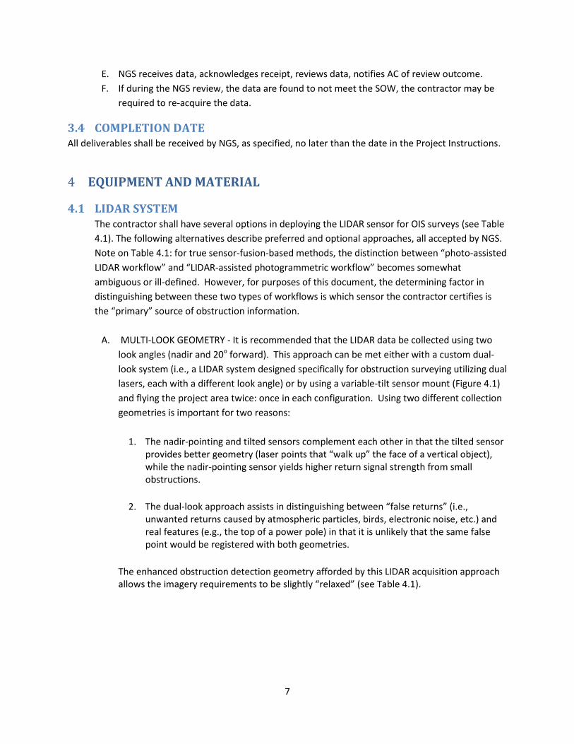
A. MULTI-LOOK GEOMETRY - It is recommended that the LIDAR data be collected using two
look angles (nadir and 20o forward). This approach can be met either with a custom dual-look system (i.e., a LIDAR system designed specifically for obstruction surveying utilizing dual lasers, each with a different look angle) or by using a variable-tilt sensor mount (Figure 4.1) and flying the project area twice: once in each configuration. Using two different collection geometries is important for two reasons:
1. The nadir-pointing and tilted sensors complement each other in that the tilted sensor
provides better geometry (laser points that “walk up” the face of a vertical object), while the nadir-pointing sensor yields higher return signal strength from small obstructions.
2. The dual-look approach assists in distinguishing between “false returns” (i.e.,
unwanted returns caused by atmospheric particles, birds, electronic noise, etc.) and real features (e.g., the top of a power pole) in that it is unlikely that the same false point would be registered with both geometries.
The enhanced obstruction detection geometry afforded by this LIDAR acquisition approach allows the imagery requirements to be slightly “relaxed” (see Table 4.1).
8
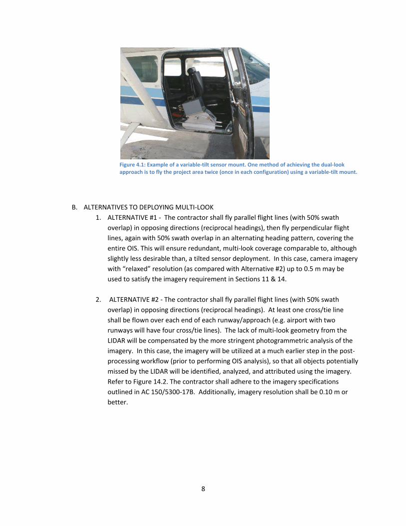
Figure 4.1: Example of a variable-tilt sensor mount. One method of achieving the dual-look approach is to fly the project area twice (once in each configuration) using a variable-tilt mount.
B. ALTERNATIVES TO DEPLOYING MULTI-LOOK 1. ALTERNATIVE #1 - The contractor shall fly parallel flight lines (with 50% swath
overlap) in opposing directions (reciprocal headings), then fly perpendicular flight lines, again with 50% swath overlap in an alternating heading pattern, covering the entire OIS. This will ensure redundant, multi-look coverage comparable to, although slightly less desirable than, a tilted sensor deployment. In this case, camera imagery with “relaxed” resolution (as compared with Alternative #2) up to 0.5 m may be used to satisfy the imagery requirement in Sections 11 & 14.
2. ALTERNATIVE #2 - The contractor shall fly parallel flight lines (with 50% swath
overlap) in opposing directions (reciprocal headings). At least one cross/tie line shall be flown over each end of each runway/approach (e.g. airport with two runways will have four cross/tie lines). The lack of multi-look geometry from the LIDAR will be compensated by the more stringent photogrammetric analysis of the imagery. In this case, the imagery will be utilized at a much earlier step in the post-processing workflow (prior to performing OIS analysis), so that all objects potentially missed by the LIDAR will be identified, analyzed, and attributed using the imagery. Refer to Figure 14.2. The contractor shall adhere to the imagery specifications outlined in AC 150/5300-17B. Additionally, imagery resolution shall be 0.10 m or better.
9
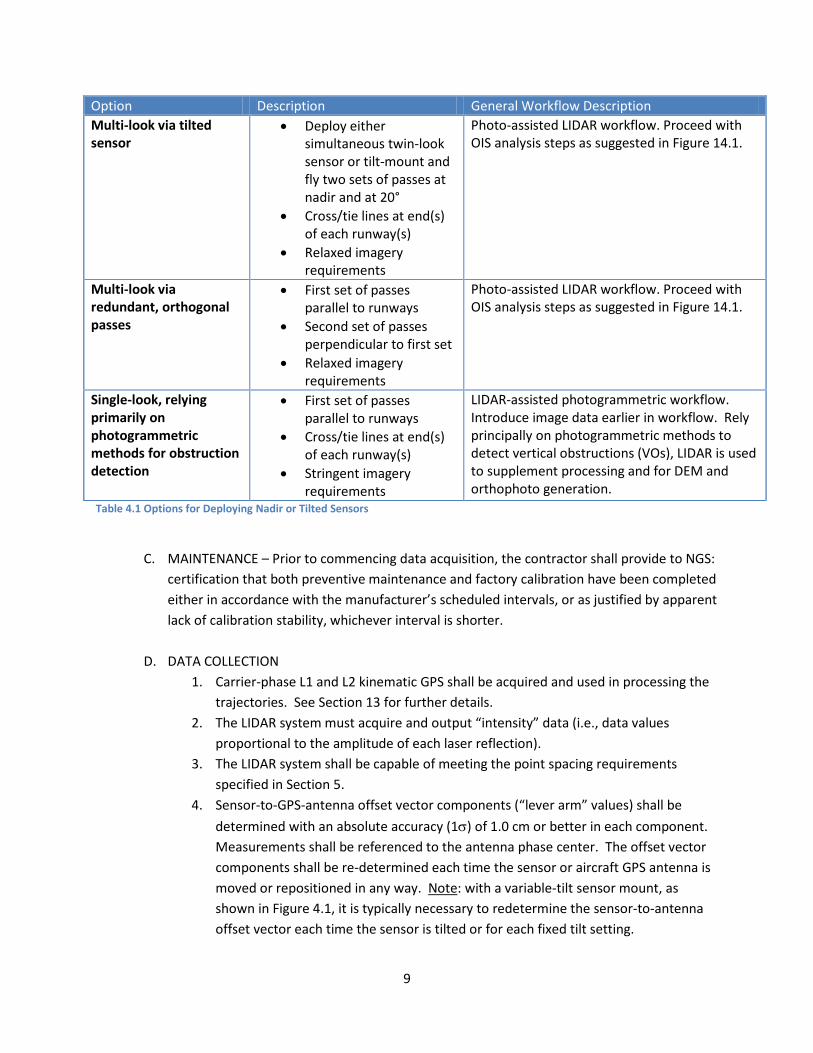
Option Description General Workflow Description Multi-look via tilted sensor
• Deploy either simultaneous twin-look sensor or tilt-mount and fly two sets of passes at nadir and at 20°
• Cross/tie lines at end(s) of each runway(s)
• Relaxed imagery requirements
Photo-assisted LIDAR workflow. Proceed with OIS analysis steps as suggested in Figure 14.1.
Multi-look via redundant, orthogonal passes
• First set of passes parallel to runways
• Second set of passes perpendicular to first set
• Relaxed imagery requirements
Photo-assisted LIDAR workflow. Proceed with OIS analysis steps as suggested in Figure 14.1.
Single-look, relying primarily on photogrammetric methods for obstruction detection
• First set of passes parallel to runways
• Cross/tie lines at end(s) of each runway(s)
• Stringent imagery requirements
LIDAR-assisted photogrammetric workflow. Introduce image data earlier in workflow. Rely principally on photogrammetric methods to detect vertical obstructions (VOs), LIDAR is used to supplement processing and for DEM and orthophoto generation.
Table 4.1 Options for Deploying Nadir or Tilted Sensors
C. MAINTENANCE – Prior to commencing data acquisition, the contractor shall provide to NGS:
certification that both preventive maintenance and factory calibration have been completed either in accordance with the manufacturer’s scheduled intervals, or as justified by apparent lack of calibration stability, whichever interval is shorter.
D. DATA COLLECTION 1. Carrier-phase L1 and L2 kinematic GPS shall be acquired and used in processing the
trajectories. See Section 13 for further details. 2. The LIDAR system must acquire and output “intensity” data (i.e., data values
proportional to the amplitude of each laser reflection). 3. The LIDAR system shall be capable of meeting the point spacing requirements
specified in Section 5. 4. Sensor-to-GPS-antenna offset vector components (“lever arm” values) shall be
determined with an absolute accuracy (1σ) of 1.0 cm or better in each component. Measurements shall be referenced to the antenna phase center. The offset vector components shall be re-determined each time the sensor or aircraft GPS antenna is moved or repositioned in any way. Note: with a variable-tilt sensor mount, as shown in Figure 4.1, it is typically necessary to redetermine the sensor-to-antenna offset vector each time the sensor is tilted or for each fixed tilt setting.
10
E. MALFUNCTIONS – All LIDAR system malfunctions shall be recorded, and NGS shall be
notified. A malfunction is defined as a failure anywhere in the LIDAR sensor that causes an interruption to the normal operation of the unit. Also, any malfunctions of the GPS or IMU collection systems shall be recorded and reported.
4.2 AIRCRAFT A. PLATFORM TYPE – The type of aircraft and the aircraft tail number used shall be stated on
the LIDAR Flight Log and all aircraft used in the performance of this Project shall be maintained and operated in accordance with all regulations required by the Federal Aviation Administration. Any inspections or maintenance of the aircraft which results in missed data collection shall not be considered as an excusable cause for delay.
B. PORT OPENING – The design of the port opening(s) in the aircraft shall be such that the field
of view is unobstructed when a sensor is mounted with all its parts. The field of view (FOV), as much as possible, shall be shielded from air turbulence and from any outward flows, such as exhaust gases, oil, etc. The port opening shall not contain any type of window (including optically-flat windows). The sensor shall have a clear view of the ground below, and no optics other than those internal to the LIDAR system and installed by the LIDAR manufacturer shall be placed in the optical path of the laser beam. This requirement is due to the fact that some attenuation of the laser radiation will occur even with coated, optically-flat windows, and this could lead to non-detection of obstructions.
5 POINT SPACING The spacing of the LIDAR data points is a critical factor in the ability to detect obstructions. Both the horizontal and vertical point spacing (defined in Sections 5.1 and 5.2, respectively) shall meet the specifications contained in Table 5.1, unless otherwise stated in the Project Instructions.
5.1 HORIZONTAL POINT SPACING Horizontal point spacing refers to the spacing of the LIDAR points on a flat surface. Horizontal point spacing is defined along two directions: along track (i.e., in the direction of flight) and across track (i.e.,
perpendicular to the direction of flight). The horizontal along-track point spacing, HPSalong, is given by
(5.1)
where is the flying speed over ground and fsc is the scan frequency. The horizontal across-track point
spacing, , is given by
11
(5.2)
where H is the flying height, S is the full scan angle PRF is the pulse repetition frequency, and τsc, is the period of the scanner (i.e., the inverse of the scan frequency). Unless otherwise stated in the Project Instructions, horizontal point spacing shall meet the specifications contained in Table 5.1 of this document.
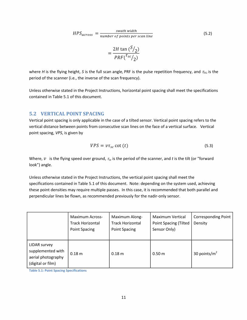
5.2 VERTICAL POINT SPACING Vertical point spacing is only applicable in the case of a tilted sensor. Vertical point spacing refers to the vertical distance between points from consecutive scan lines on the face of a vertical surface. Vertical point spacing, VPS, is given by
(5.3)
Where, is the flying speed over ground, τsc is the period of the scanner, and t is the tilt (or “forward look”) angle. Unless otherwise stated in the Project Instructions, the vertical point spacing shall meet the specifications contained in Table 5.1 of this document. Note: depending on the system used, achieving these point densities may require multiple passes. In this case, it is recommended that both parallel and perpendicular lines be flown, as recommended previously for the nadir-only sensor.
Maximum Across-Track Horizontal Point Spacing
Maximum Along-Track Horizontal Point Spacing
Maximum Vertical Point Spacing (Tilted Sensor Only)
Corresponding Point Density
LIDAR survey supplemented with aerial photography (digital or film)
0.18 m 0.18 m 0.50 m 30 points/m2
Table 5.1: Point Spacing Specifications
12
6 RADIOMETRIC QUALIFICATION TEST This section describes a recommended test and proposed equipment to be developed and maintained at NOAA/NGS. At present, this equipment has not been constructed, so the responsibility for performing this test, if required, is solely that of the contractor.
The objective of the test procedures described here is to radiometrically qualify LIDAR systems for airport obstruction surveying. The outputs of this test are the maximum qualified operating height, hmax, for the system and the minimum ground sampling density, , for that system. This test qualifies an individual, unique system, and it is not intended as a type qualification test.
This test is constructed for single-beam, scanned-spot architecture, 1064 nm LIDAR instruments, and any other instrument architectures proposed for use should be qualified in the spirit of this test. For example, a multi-beam LIDAR system would require a measurement for each beam in the system, and the result would require flight planning based on the worst-case maximum flying height and the worst-case sample density, even if they result from different beam data elements. Instruments designed to operate at different wavelengths (e.g. 1550 nm) would require a reflectance standard with Lambertian characteristics and would require a measurement of , the target reflectance, at the operating wavelength.
The radiometric performance of a LIDAR system is critical in obstruction detection. Systems qualified by this test, and operated at an altitude above-ground-level (AGL) less than or equal to the maximum operating altitude (calculated by the methodology of this section) and at a sample density greater than or equal to the minimum operating density (calculated by the methodology of this section) have a high likelihood of detecting small-diameter, low-reflectance obstructions, such as dark-colored poles and antennas.
The test procedures have been designed to meet the following requirements:
• Provide a common reference so that the results from different manufacturers’ LIDAR systems will have the same meaning.
• Provide a method that specifically tests the ability of the LIDAR system to detect small-diameter obstructions, such as antennas and poles.
• Utilize a ground-based, controlled test environment. • Ensure repeatability of the results.
This test will be carried out under the oversight of NOAA personnel at the proposed NOAA LIDAR Radiometric Calibration Center (LRCC) at Corbin, VA, unless written consent is granted by NOAA for the contractor to perform an in-flight radiometric performance test in lieu of the test described below. The test setup is illustrated in Figure 6.1.
The test target consists of a one-half inch diameter wood dowel painted with Kodak White Reflectance Coating. This coating provides a standard reflectance of nearly 100% at a 1064 nm wavelength and has Lambertian reflectance properties.
A minimum of two configurations shall be tested; 1) with the LIDAR directed to its nadir position and, 2) with the LIDAR directed to the maximum angular excursion planned for the OIS survey activity. The intention of measuring at multiple angular positions is that the internal optical characteristics of the LIDAR instrument may not allow equal radiometric efficiency at different scan angles. This test is intended to determine the minimum return signal within the planned operational angular range for the instrument under test.
13
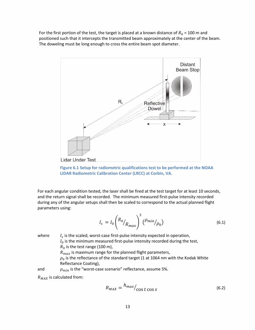
For the first portion of the test, the target is placed at a known distance of = 100 m and positioned such that it intercepts the transmitted beam approximately at the center of the beam. The doweling must be long enough to cross the entire beam spot diameter.
Figure 6.1 Setup for radiometric qualifications test to be performed at the NOAA LIDAR Radiometric Calibration Center (LRCC) at Corbin, VA.
For each angular condition tested, the laser shall be fired at the test target for at least 10 seconds, and the return signal shall be recorded. The minimum measured first-pulse intensity recorded during any of the angular setups shall then be scaled to correspond to the actual planned flight parameters using:
(6.1)
where is the scaled, worst-case first-pulse intensity expected in operation, is the minimum measured first-pulse intensity recorded during the test, is the test range (100 m), is maximum range for the planned flight parameters,
is the reflectance of the standard target (1 at 1064 nm with the Kodak White Reflectance Coating),
and is the “worst-case scenario” reflectance, assume 5%.
is calculated from:
(6.2)
14
where is the maximum flying height (AGL), t is the tilt (“forward look”) angle, and s is the maximum half scan angle from the flight plan.
By defining two correction factors and rearranging to isolate :
(6.3)
where sets an acceptable safety margin (usually 110%), and is an atmospheric loss correction factor in the range 1.1-1.3 ( ).
7 SPOT SPACING QUALIFICATION TEST A follow-on to the radiometric testing (leveraging the radiometric test setup) will calculate the minimum required sample spacing for the system being qualified. The setup for this test is the same as the first part, but the horizontal position of the target will be adjusted to find the detectable limit of the LIDAR on each side of the beam.
The target shall be removed from the beam to one side and slowly introduced to the illuminated area. The system under test shall be monitored until it is indicating valid ranges at with no dropouts (dropout count/readout ≈ “0”) indicated. The intensity reported, I1, shall be recorded. The target shall be translated to the other side of the beam until the system indicates dropouts (dropout count/readout ≠ “0”). The intensity, I2, shall be recorded. The target shall be translated out of the beam on this side, and then the process repeated in the other direction to measure I3 and I4. If valid ranges are reported at intensity values of 0, the intensity values shall be recorded as the least non-zero value possible (normally a gray scale value of 1).
The half maximum intensity shall be calculated by:
(7.1)
The horizontal position of the half maximum intensity points shall be measured by the same target translation technique used to measure the minimum detectable intensities. The average of the two horizontal measures will be used to calculate the angular full width at half maximum, FWHM, of the beam by:
(7.2)
(7.3)
By noting that the LIDAR divergence angles are usually very small, Equation 7.3 can be approximated as:
15
(7.4)
Then, the minimum sample density requirement for this system shall be:
(7.5)
When this test has been carried out under the oversight of NOAA personnel at the NOAA LIDAR Radiometric Calibration Center (LRCC) at Corbin, VA, then the NOAA observer will provide a signed Certificate of Qualification for the system under test, including a description of the system, the serial number of the system, the date of the system test and the values of the system’s qualified parameters ( and ).
8 SYSTEM CALIBRATION Inadequate calibration or incomplete calibration reports may be considered cause for rejection of the data. Calibration reports for each LIDAR system used shall be supplied to NGS at the beginning and end of the project. The calibration reports shall cover each of the following types of calibration:
8.1 FACTORY CALIBRATION Factory calibration of the LIDAR system shall address both radiometric and geometric performance and calibration. (Note: the factory radiometric calibration does not obviate the need for the radiometric qualification test for obstruction surveying described in the previous section). The following briefly describes the parameters to be tested according to test procedures defined by the manufacturer. Some of these procedures and parameters may be unique to a manufacturer since hardware varies from manufacturer to manufacturer.
A. Radiometric Calibration (sensor response):
• Ensure that the output of the laser meets specifications for pulse energy, pulse width, rise time, frequency, and divergence for the model of LIDAR being tested.
• Measure the receiver response from a reference target to ensure the response level of the receiver is within specification for the model of LIDAR system being tested.
• Check the alignment between transmitter and receiver and certify that the alignment is optimized and within specification.
• Measure T0 response of receiver (i.e., the response at the time the laser is fired) to ensure the T0 level is within specification.
B. Geometric Calibration:
• Range Calibration – Determine rangefinder calibrations including first/last range offsets, temperature dependence, and frequency offset of rangefinder electronics, range dependence on return signal strength. Provide updated calibration values.
• Scanner Calibration – Verify that scanner passes accuracy and repeatability criteria. Provide updated scanner calibration values for scanner offset and scale.
• Position Orientation System (POS)-Laser Alignment – Alignment check of output beam and POS. Also, provide updated POS misalignment angles.
16
Overall, the system shall be tuned to meet the performance specifications for the model being calibrated. The contractor shall ensure that, for each LIDAR system used, factory calibration has been performed within the manufacturer’s recommended interval or more frequently, if required to demonstrate a stable calibration to NGS. Contractors who wish to apply for a waiver for this requirement shall send a written request to NGS stating the date of the last factory calibration and a detailed justification for the waiver.
8.2 BORESIGHT/IN-SITU CALIBRATION Sensor calibration is required to reduce or eliminate systematic errors in the LIDAR data. Specifically, the calibration procedures involve solving for a set of calibration parameters that minimize the mean square error (or satisfy some other statistical optimality criterion) using ground control and data in overlapping swaths. The specific set of calibration parameters is a function of the optical sensor model for the specific system, but may include, for example: roll, pitch, and range offsets, scanner scale and offset, or higher order polynomial coefficients. If performed properly, this calibration will ensure the highest possible data accuracy, while also eliminating artifacts in the data, such as discontinuities (vertical jumps) in swath overlap areas near the edges of scan lines, horizontal offsets between peaked rooftop positions in data from opposing flightlines, etc. This calibration shall be performed for each project or every month, or as dictated by analysis of the data, whichever interval is shortest. Additionally, any calibration procedure that employs software shall be documented and the reports generated by the software shall be supplied to NGS along with a basic description of the software.
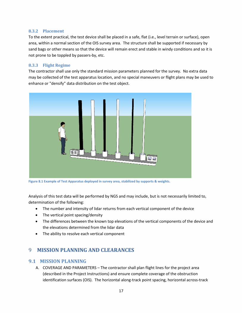
8.3 FIELD TEST/VALIDATION The contractor shall place a special test device within the survey area so that a validation of the system performance can be made. The device will simulate real-world conditions of potential objects that might intersect and protrude above the OIS and should be detectable by the LIDAR sensor. Point-cloud data of the object should appear in the complete data-set.
8.3.1 Apparatus & Configuration The equipment apparatus shall consist of the following materials:
1. A base plate or tube approximately 10’ in length 2. (2) 6” diameter sections of PVC pipe, 8’ in length, (1) black-color, (1) white-color 3. (2) 4” diameter sections of PVC pipe, 8’ in length, (1) black-color, (1) white-color 4. (2) 2” diameter sections of PVC pipe, 8’ in length, (1) black-color, (1) white-color
The 8’ PVC sections shall be vertically mounted to the base plate/support such that they are as plumb as possible. The base plate must have two marks, one at each end, to geolocate the test apparatus once installed in the survey area. Refer to Figure 8.1 for an example.
17
8.3.2 Placement To the extent practical, the test device shall be placed in a safe, flat (i.e., level terrain or surface), open area, within a normal section of the OIS survey area. The structure shall be supported if necessary by sand bags or other means so that the device will remain erect and stable in windy conditions and so it is not prone to be toppled by passers-by, etc.
8.3.3 Flight Regime The contractor shall use only the standard mission parameters planned for the survey. No extra data may be collected of the test apparatus location, and no special maneuvers or flight plans may be used to enhance or "densify" data distribution on the test object.
Figure 8.1 Example of Test Apparatus deployed in survey area, stabilized by supports & weights.
Analysis of this test data will be performed by NGS and may include, but is not necessarily limited to, determination of the following:
• The number and intensity of lidar returns from each vertical component of the device
• The vertical point spacing/density
• The differences between the known top elevations of the vertical components of the device and the elevations determined from the lidar data
• The ability to resolve each vertical component
9 MISSION PLANNING AND CLEARANCES
9.1 MISSION PLANNING A. COVERAGE AND PARAMETERS – The contractor shall plan flight lines for the project area
(described in the Project Instructions) and ensure complete coverage of the obstruction identification surfaces (OIS). The horizontal along-track point spacing, horizontal across-track

18
point spacing, vertical point spacing, swath width, swath overlap, navigation, GPS, visibility, point density, and radiometric considerations shall be taken into account in flight planning. NGS may supply recommendations and/or requirements for planning parameters in the Project Instructions.
Planning an OIS survey is not like planning a terrain survey. The objective is not to achieve the most efficient coverage within a bounding box on a 2D coordinate basemap. Rather, OIS surveys require the capture and identification of objects that project above an abstract and complex-shaped surface which is described above the terrain. The three figures in this section help to illustrate the objective, and the risk of failure that a traditional planning method might introduce.
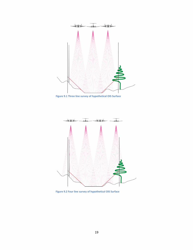
The first illustration (Figure 9.1) presents a cross-section of the terrain taken through a runway and extending to the sides. The cross-section of the OIS is indicated in red and the terrain in brown. Vertical lines are edge delimiters for the OIS, analogous to the bounding box edges in a traditional plan. Based on a conventional survey plan, the survey might be executed in three passes, with a small edge-lap to efficiently cover a terrain survey. However, if this plan were actually used for the OIS survey, the tower on the left edge would be missed and the tree on the right edge would be under-represented. Both objects exist within the OIS and must be fully presented in the data.
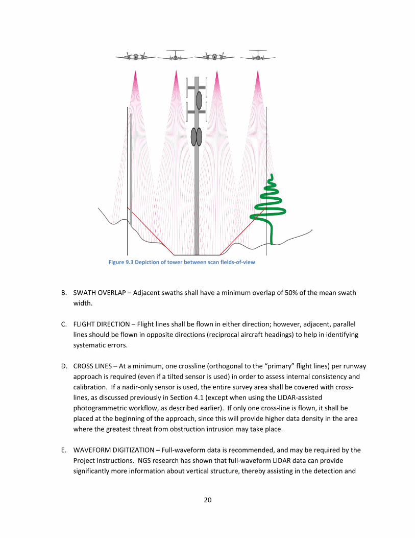
The second illustration (Figure 9.2) changes the plan to include data collection beyond the traditional limits of topographic collection to enable the inclusion of the full height of the tower and a complete representation of the tree. The most important difference between the two plans is that the second has accounted for the need to capture all objects extending above the OIS and recognized that the scanned LIDAR beam has a maximum vertical extent which is a function of the scan angle. Capturing the entire vertical extent of any objects above the OIS’s horizontal extents is a requirement, so the volume sampled must extend well above the abstract surface itself. Although not as common, a related problem that can occur is missing or under-reporting the tops of very tall objects, which fall between the FOVs of adjacent swaths, as shown in Figure 9.3. This situation can be mitigated with increased swath overlap and perpendicular cross-lines. However, since this problem typically only affects the very tallest objects in the scene (e.g., 300-m TV broadcast towers), and since these extremely tall objects are typically known to exist in the scene prior to the survey, special care can be taken in project planning to ensure they are adequately captured (e.g., with a flight line directly overhead).
19
Figure 9.1 Three line survey of hypothetical OIS Surface
Figure 9.2 Four line survey of hypothetical OIS Surface
20
B. SWATH OVERLAP – Adjacent swaths shall have a minimum overlap of 50% of the mean swath width.
C. FLIGHT DIRECTION – Flight lines shall be flown in either direction; however, adjacent, parallel
lines should be flown in opposite directions (reciprocal aircraft headings) to help in identifying systematic errors.
D. CROSS LINES – At a minimum, one crossline (orthogonal to the “primary” flight lines) per runway approach is required (even if a tilted sensor is used) in order to assess internal consistency and calibration. If a nadir-only sensor is used, the entire survey area shall be covered with cross-lines, as discussed previously in Section 4.1 (except when using the LIDAR-assisted photogrammetric workflow, as described earlier). If only one cross-line is flown, it shall be placed at the beginning of the approach, since this will provide higher data density in the area where the greatest threat from obstruction intrusion may take place.
E. WAVEFORM DIGITIZATION – Full-waveform data is recommended, and may be required by the
Project Instructions. NGS research has shown that full-waveform LIDAR data can provide significantly more information about vertical structure, thereby assisting in the detection and
Figure 9.3 Depiction of tower between scan fields-of-view

21
recognition of objects in the survey site. If full-waveform data are to be utilized, the contractor shall submit a description of the waveform post-processing strategy to NGS prior to the survey.
F. LIDAR SURVEY PLAN REPORT
1. PROPOSED FLIGHT LINES – Prior to data acquisition, the contractor shall submit paper
map(s), or shapefiles, or KML/KMZ files clearly showing all proposed flight lines, and also depicting coverage, proposed ground control, and OIS boundaries. Information about scan angle, pulse repetition frequency (PRF), flying height, flying speed over ground, and horizontal and vertical point spacing shall also be included.
2. ACTUAL LINES FLOWN – Similar map(s) or files showing the actual flight lines shall be
included in the Final Report, see Section 13.
9.2 FLYING HEIGHT Flying height is an extremely important factor in obstruction detection in that the received power from obstructions falls off as the 2nd, 3rd or 4th power of the range, depending on the laser radar cross section of the target. Hence, to ensure a high-probability of obstruction detection, it is typically desirable to fly as low as possible, within the applicable eye-safety limits. Depending on the airport and the minimum eye-safe altitude, this may necessitate airspace coordination.
9.3 FLIGHT CLEARANCES The contractor shall comply with all required Federal Aviation Administration Regulations, including obtaining all required clearances.
10 EYE SAFETY Because LIDAR systems typically employ Class 4 lasers, safety is a paramount concern. See ANSI Z136.1 Safe Use of Lasers and ANSI Z136.6 Safe Use of Lasers Outdoors for applicable standards. For further details regarding safety issues in LIDAR data collection, refer to Eye Safety Concerns in Airborne LIDAR Mapping (Flood, 2001). The contractor shall assume sole responsibility for adherence to all safety regulations and shall implement necessary internal controls to ensure the safety of all persons in the aircraft and in the survey area below.
11 IMAGERY Stereo aerial photography, collected with a film or digital mapping-grade (geometrically calibrated and stable) camera, is an important complement to the LIDAR data in that it enables the following functions to be performed:
22
• Quality assurance/quality control • Feature attribution • Outlier removal • Independent obstruction identification/measurement
Imagery shall be collected in accordance with FAA AC 150/5300-17B, or more recent version of this AC, unless otherwise stated in the Project Instructions. Imagery acquisition shall be performed by the contractor no earlier/ later than two weeks prior to/after the completion of the LIDAR data acquisition. No exception to the ± 2 week window is allowed without prior written approval from NGS or unless waived in the Project Instructions. To the extent possible, ground control for the imagery and LIDAR data should constitute the same set of points. Standard photo targets (traditionally used for aerotriangulation and not widely used with a direct georeferencing subsystem), also provide a suitable target for the LIDAR. Due to the high reflectivity and large size, these targets are not only observable in the aerial imagery collected with a camera, they also appear as high-intensity (on a standard grey scale) points in a LIDAR point cloud. Photo control shall meet the requirements outlined in AC 150/5300-17B. In any case, it is strongly recommended that suitable types and locations for control be used such that they are readily identifiable in BOTH the imagery and LIDAR data. Ground control points shared between the LIDAR data and imagery, and those collected for LIDAR only, shall be tied to the National Spatial Reference System (NSRS), referenced to North American Datum of 1983 (NAD 83), and shall have horizontal and vertical accuracies, at the 95% confidence level, of 10 cm and 20 cm, respectively.
12 WEATHER AND TIME OF YEAR
12.1 WEATHER CONDITIONS LIDAR data acquisition missions shall be flown in favorable weather. Inclement weather conditions such as rain, snow, fog, mist, high winds, and low cloud cover shall be avoided. In addition, to ensure low atmospheric attenuation and high return signal strength, Visual Meteorological Conditions (VMC) and visibility of at least 8 nautical miles are required. If clouds are present, data capture is only permitted if cloud coverage is above the height of the sensor and airborne platform. LIDAR shall not be conducted
when the ground is covered by water (flood), snow, or ice. If a 1.5 µm laser wavelength is used, special attention should be paid to ground surface wetness and humidity.
12.2 TIME OF DAY Data acquisition operations may occur during either day or night. Unlike aerial photography, sun angle is not a factor in mission planning for LIDAR. However, time of day needs to be considered when imagery is acquired concurrently with the capture of LIDAR data to help assist in identifying features in post-processing production.
23
12.3 TIME OF YEAR For obstruction detection, the contractor shall fly in leaf-on conditions, as this increases the probability of detecting the tops of trees. For most geographic locations, data acquisition shall be completed before late fall. The Project Instructions will contain specific recommendations and/or requirements.
13 POSITIONING AND ORIENTATION FOR THE DATA
13.1 POSITIONING A. GPS COLLECTION
1. All LIDAR data shall be georeferenced using integrated GPS/inertial systems
employing dual frequency receivers. 2. All kinematic GPS (KGPS) solutions should use differential, ionosphere-free, carrier-
phase combinations with phase ambiguities resolved to their integer values. 3. Aircraft trajectories shall be processed using carrier-phase GPS. Dual L1 and L2
frequency receivers and one-second or better collection shall be used. 4. All KGPS shall use at least two ground stations. The ground stations shall be
accurately tied to the National Spatial Reference System (NSRS) using OPUS; shall be positioned to 0.1 meter accuracy, or better; shall be within or near the project area; and shall be within 100 kilometers of the entire project area. Additional ground GPS stations may be required, and continuously operating reference stations (CORS ) can be used as ground stations. The ground stations should be positioned on opposite sides of the operating area. The ground stations shall be positioned, or the flight path arranged, so that during flight operations the aircraft will, at least once, pass within 10 kilometers to each ground station.
5. The maximum GPS baseline shall not exceed 100 kilometers at any time during flight. Regardless of aircraft flight time, GPS ground station data shall be collected for four hours.
6. Ground station data shall be submitted to OPUS (Online Positioning User System – http://www.ngs.noaa.gov/OPUS/) for positioning in the NSRS, even if the ground station is set up over a known survey monument in the NGS Database.
B. GPS SOLUTION PROCESSING
1. The contractor shall collect, process, and submit the ground and airborne GPS data—both raw data and final processed data.
2. Differential KGPS solutions for the aircraft shall be obtained independently using each ground station.
3. These independent KGPS solutions shall be compared to report their differences in the north-south, east-west, and vertical components during the operational portions of the flights.
4. The RMS of these differences shall not exceed 5 cm in the horizontal and 10 cm in the vertical.
5. The KGPS solutions shall model the tropospheric delay using average surface meteorological values at the ground stations collected near the midpoint of
24
operations. Supporting metadata shall be supplied to NGS. 6. The final KGPS solution will be an average of the separate ground station solutions.
C. ANTENNA 1. The GPS receivers should be equipped with NGS-approved antennas. A choke-
ring antenna to minimize multipath is preferred but not required. 2. The antenna height shall be accurately measured.
13.2 GROUND-BASED GPS RECEIVER A. MARK – The ground-based receiver shall be set up over a known (or to-be-determined)
marked base station and shall run continuously during the mission. If a known base station is used, it shall be in the NGS database and hence part of the NSRS. If a new base station is used, it shall be marked permanently (to NGS specifications) or temporarily marked (such as a PK type nail or iron pin).
B. OBSERVATIONS – The position of an existing mark shall be checked by processing one GPS
session and comparing the computed position with the NGS published position. A new mark shall be referenced to the NSRS by tying to one or more NGS CORS by static GPS methods. If the distance to the nearest NGS CORS is less than 50 miles, use at least two independent sessions, each 2 hours long. If the distance to the nearest NGS CORS is greater than 50 miles, use at least two sessions, each 4 hours long. Make a separate tripod set-up and height measurement for each session. Take care in the accurate recording of the height of the antenna both before and after the flight. Record all heights, equipment serial numbers, etc. on the NGS forms: Visibility Obstruction Diagram and GPS Observation Log. For a listing of these and other forms on the NGS website see: www.ngs.noaa.gov/PROJECTS/FBN/. Also, it is recommended that static observations be processed using the NGS “On-Line User Positioning Service” (OPUS) found at: www.ngs.noaa.gov/OPUS/index.html. Observations to establish a new, permanent mark shall be submitted in NGS “Blue Book” format.
C. RECOVERY – For an existing NSRS station, write a digital recovery note using the online Mark
Recovery Form: http://www.ngs.noaa.gov/FORMS_PROCESSING-cgi- in/recvy_entry_www.prl. For a new, permanent station, write a digital station description in NGS format using WINDESC. For a new, temporary mark, write a brief description adequate to recover the station. Take three photographs of the base station to NGS specifications. (Photographs of CORS stations are not required.)
For additional specification guidance on mark setting, GPS observations, data processing, and data submittal in NGS format, see FAA AC 150/5300-16A and the “General Specifications for Aeronautical Surveys, Volume I, Establishment of Geodetic Control on Airports” at:
• www.ngs.noaa.gov/AERO/Supinst.html • www.ngs.noaa.gov/FGCS/BlueBook/ • www.ngs.noaa.gov/PROJECTS/FBN/
25
13.3 AIRCRAFT GPS RECEIVER A. GPS OBSERVATIONS – The aircraft GPS receiver shall be capable of collecting carrier phase
observations and recording at least once per second from a minimum of four satellites (five or more preferred), for post- processing. All data shall be collected with a Position Dilution of Precision (PDOP) of less than 3. Final (Precise) or Rapid orbits—not Ultra Rapid—shall be used in the post-processing.
B. GPS LOCK – The aircraft shall maintain GPS satellite lock throughout the entire flight mission.
If satellite lock is lost, on-the-fly ambiguity resolution methods may be used to recapture lock while airborne. Report these instances, procedures used, and any other unusual occurrences. The GPS post-processing software may be capable of providing an output log of all incidents, such as loss of GPS satellite lock. The formatted output log is acceptable as the report.
13.4 AIRBORNE ORIENTATION An Inertial Measurement Unit (IMU) shall be incorporated into the LIDAR unit. The IMU system shall be capable of determining the absolute orientation (roll, pitch, and yaw) at a minimum of 200 Hz and an absolute accuracy (RMSE) of 0.02 deg in roll and pitch and 0.08 deg in heading. Boresight calibration shall be performed so that the accurate orientation of each laser pulse can be determined (Section 8.2).
13.5 AIRBORNE POSITIONING AND ORIENTATION REPORT The Report shall include at least the following paragraphs: – Introduction, – Positioning – Data Collection – Static Processing – Kinematic Processing
– Data Sets – Orientation – Data Collection – Data Processing – Data Sets – Final Results.
A. INTRODUCTION – Provide an overview of the project and the final processed data sets, and list the data sets in table form with the following columns: Dataset ID, Date of Acquisition, Projects Covered, and Description/Flight Line(s) Identification.
B. POSITIONING – Discuss the methodology, the hardware and software used (including models,
serial numbers, and versions), the PACS, SACS, and/or CORS station(s) used, a general description of the data sets, flight lines, dates and times of sessions, the processing (including the type of solution–float, fixed, ion–free, etc.), and the results (discussion of the coordinates and accuracy). Submit a description of the data sets and the raw and processed data. If the NGS OPUS website was used to process the static data, the contractor shall provide a copy of
26
the OPUS report. If a known station was used from the NGS database, the contractor shall identify the station by name and permanent identifier (PID), and provide the comparison of the published position to the newly-determined position, and the coordinates used in the kinematic position step (see Section 13.2B). If multiple base stations were used, provide processing details, coordinates, and accuracy for all stations.
C. ORIENTATION – Discuss the factors listed above for Positioning.
D. FINAL RESULTS – Describe any unusual circumstances or rejected data, and comment on the
quality of the data.
14 OIS ANALYSIS WORKFLOW
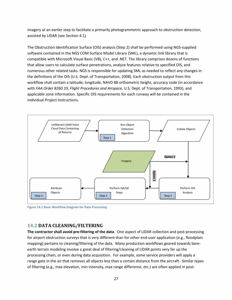
14.1 ANALYSIS WORKFLOW Generating final obstruction data from the LIDAR point cloud is a nontrivial task. For example, it is possible (even simple) to analyze the raw LIDAR point cloud against the OIS and extract only penetrating points. However, this is generally not a good idea, as it complicates the following tasks: 1) distinguishing between returns from real objects and those due to noise or clutter, 2) determining which points correspond to laser reflections from the same object, and 3) attributing detected obstructions. Based on research conducted by NGS, as well as valuable information obtained from private sector survey firms engaged in LIDAR airport survey, the generic workflow depicted graphically in Figure 14.1 is recommended. One critical aspect of this workflow is the placement of the object detection step before the OIS analysis step, so that the OIS analysis is performed on extracted objects (e.g., trees, buildings, antennas, poles, towers, etc.), rather than on the raw LIDAR points. Note: all detection algorithms and processes employed by the contractor shall be described thoroughly in a step-by-step approach in the appropriate sections of the final report.
The sequence of steps in this workflow has been ordered such that, irrespective of the specific detection algorithm used, the detection threshold can be set very low to minimize the probability of a miss (or, equivalently, maximize probability of detection). Object detection and collation are performed first, followed by the OIS analysis, then object-type attribution using the aerial imagery, and finally, verification and validation. False alarms (or “false objects”) due to ground clutter or noise and randomly distributed throughout the project area will typically be automatically eliminated in the OIS analysis step, due to not penetrating or falling outside the OIS, and the remainder can be easily removed during the image analysis steps. This inherent tolerance of conservative detection thresholds in the object extraction process is an important aspect of the workflow, since the key consideration in airport obstruction surveying is to avoid missed obstructions that could potentially jeopardize flight safety. The imagery input is critical, as the imagery provides a complementary and independent data source. For a more in-depth discussion of the workflow benefits, refer to “Improved Approach to LIDAR Airport Obstruction Surveying Using Full-Waveform Data,” Journal of Surveying Engineering, Vol. 135, No. 2, pp. 72-82, Parrish and Nowak, 2009. Also, a slight variation on the workflow entails introducing the aerial
27
imagery at an earlier step to facilitate a primarily photogrammetric approach to obstruction detection, assisted by LIDAR (see Section 4.1). The Obstruction Identification Surface (OIS) analysis (Step 2) shall be performed using NGS-supplied software contained in the NGS COM Surface Model Library (SML), a dynamic-link library that is compatible with Microsoft Visual Basic (VB), C++, and .NET. The library comprises dozens of functions that allow users to calculate surface penetrations, analyze features relative to specified OIS, and numerous other related tasks. NGS is responsible for updating SML as needed to reflect any changes in the definitions of the OIS (U.S. Dept. of Transportation, 2008). Each obstruction output from this workflow shall contain a latitude, longitude, NAVD 88 orthometric height, accuracy code (in accordance with FAA Order 8260.19, Flight Procedures and Airspace, U.S. Dept. of Transportation, 1993), and applicable zone information. Specific OIS requirements for each runway will be contained in the individual Project Instructions.
Figure 14.1 Basic Workflow Diagram for Data Processing
14.2 DATA CLEANING/FILTERING The contractor shall avoid pre-filtering of the data. One aspect of LIDAR collection and post-processing for airport obstruction surveys that is very different than for other end-user application (e.g., floodplain mapping) pertains to cleaning/filtering of the data. Many production workflows geared towards bare-earth terrain modeling involve a great deal of filtering/cleaning of LIDAR points very far up the processing chain, or even during data acquisition. For example, some service providers will apply a range gate in the air that removes all objects less than a certain distance from the aircraft. Similar types of filtering (e.g., max elevation, min intensity, max range difference, etc.) are often applied in post-
Option 1
Perform OIS Analysis
Perform QA/QC Steps
Attribute Objects
Run Object Detection Algorithm
Unfiltered LIDAR Point Cloud Data Containing
all Returns Collate Objects
Imagery
Step 1
Step 2 Step 3 Step 4
Option 2
28
processing. For airport obstruction surveying, this type of cleaning is very dangerous, as it can easily lead to removing points corresponding to reflections from obstructions, in some cases causing these obstructions to be missed. Therefore, the contractor shall deliver the raw LIDAR point cloud (with absolutely no points removed either in the air or in post-processing) as one of the Deliverables. Additionally, the contractor shall be extremely careful about any cleaning or filtering done during the analysis workflow described above. In general, it is best to leave all points to be input to Step 1 from the LAS file and allow the Object Detection step to handle filtering. Any pre-cleaning/filtering performed should be explicitly described in the report. Additionally, these filtered points shall not be removed from the LAS file; instead they should be kept and attributed as “withheld” in the LAS file (classification bit encoding).
15 DATA LABELING All hard drives shall be labeled with the project name, collection date(s), contractor name, and disk contents. LIDAR data hard drives shall be able to be easily matched with the corresponding LIDAR flight log(s).
16 DATA SHIPMENT AND PROCESSING
16.1 SHIPMENT The contractor shall ship final deliverables in NGS format (on hard disk), to arrive at NGS within ten working days from the date of completion of data processing. Copies of the LIDAR Flight Log and the raw navigation files may be made and used by the contractor to produce and check the final deliverables.
16.2 NOTIFICATION The same day as shipping, the contractor shall notify NGS of the data shipment’s contents and date of shipment by transmitting to NGS a paper or digital copy of the data transmittal letter via email or fax.
17 DELIVERABLES The following list outlines the required deliverables resulting from Airport OIS Survey work. Additional or custom deliverables may be described in individual Project Instructions. The contractor is also responsible for providing all required deliverables in FAA AC 150/5300-17B and FAA AC 150/5300-18B unless otherwise stated. If the contractor finds a contradiction or redundancy, NGS shall be notified.
A. LIDAR SURVEY AND QUALITY CONTROL PLAN – Prior to data acquisition, submit a proposed
LIDAR Survey and Quality Control Plan specifying the data collection parameters to be used and containing a map of the flight lines and the project coverage area, including flying
29
height, speed over ground, scan angle, PRF, overall density, and horizontal and vertical point spacing,. NGS will review the proposed mission planning reports, normally within five business days, and will respond in writing with approval and/or comments. The Final Report shall contain map(s) showing the flight lines and boundaries of LIDAR data actually collected.
B. GPS SURVEY LOCATION OF TEST APPARATUS DESCRIBED IN SECTION 8.3.3. C. LIDAR RAW DATA – Submit the completed data collection raw output. D. LIDAR PRODUCTS – Required products include: LIDAR point cloud files, intensity images,
attributed objects/obstructions and other products described in AC17B and AC18B. The Project Instructions will specify which additional products, if any, are required. See 3.1 D.
E. IMAGERY - All imagery shall be delivered according to the format and requirements outlined in FAA AC 150/5300-17B, specifically Sections 19-22 inclusive.
F. FLIGHT REPORTS – Submit the completed, original LIDAR Flight Logs with the data, as well as
a copy directly to NGS. G. GLOBAL POSITIONING SYSTEM (GPS)/INERTIAL MEASUREMENT UNIT (IMU) FILES – The
contractor shall submit the original, raw data files and processed trajectory files, to arrive at NGS along with the raw data points and final products. See Sections 12.1 and 12.4.
H. AIRBORNE POSITIONING AND ORIENTATION REPORT – Submit raw GPS and IMU data (in the
manufacturer’s format) with the final processed GPS trajectory and post-processed IMU data. Also submit a report covering the positioning and orientation of the LIDAR. See Section 11.5.
I. RANGE AND SCANNER ANGLE FILES – The contractor shall submit the original, raw data files
directly to NGS, to arrive at NGS along with the raw data points and final products. J. GPS CHECK POINTS – Submit an organized list of all GPS points used for the project as base
stations and check points. Indicate which GPS points are pre-existing ground control and which stations are new and positioned relative to the NSRS. See Project Instructions and Sections 3.1 C and 12.2.
K. NGS SURVEY FORMS – The contractor shall prepare and submit the following NGS forms for
each GPS check point and the GPS base station(s): Visibility Obstruction Diagram, GPS Observation Log, Recovery Note or Station Description. See Section 12.2.
L. CALIBRATION REPORTS – There is no standard format for the calibration reports. However,
the calibration reports shall contain, at a minimum, the following information:
30
• The date the calibration was performed.
• The name of the person, company, or organization responsible for performing the calibration.
• The methods used to perform the calibration.
• The final calibration parameters or corrections determined through the calibration procedures.
• A discussion of the results. M. SENSOR MAINTENANCE – Provide maintenance history of the sensor to be used for
acquiring LIDAR. See Section 4.1.
N. DATA SHIPMENT – See Sections 3 and 15 for instructions.
O. DATA SHIPMENT REPORTING – The contractor shall notify NGS of each data shipment’s contents and date of shipment by transmitting to NGS a paper or digital copy of the LIDAR Flight Log (marked “copy” at the top) and a copy of the data transmittal letter via email or facsimile. This shall be done the same day the data is shipped to the data processing contractor. See Section 15.
P. UNUSUAL CIRCUMSTANCES – The contractor shall also notify NGS of any unusual circumstances that occur during the performance of this project which might affect the deliverables or their quality and particularly of any deviation from this project. This may be included in the weekly email required below, unless urgent.
Q. DEVIATIONS FROM SCOPE OF WORK – Requests to exceed or deviate from the Project Instructions will be considered if written justification is provided to NGS in advance. No deviation is permitted until written approval is received from NGS.
R. STATUS REPORTS – The contractor shall submit project status reports via email to the Contractor Officer’s Representative (COR) contacts in Section 14 every week, until the work is complete. These reports are due at NGS by 2:00 p.m. EST each Monday. The reports shall include a summary of completed data acquisition, with dates completed; data shipped, and dates; and any unusual circumstances, equipment malfunctions, and/or any disturbance of the sensor. A weekly status report is required even if no progress has been made.
S. FINAL REPORT The contractor shall supply to NGS a Final Report incorporating all of the information in this Deliverables section including, at least, the sections listed below: 1. Work performed under this contract, discuss each deliverable including: the
maximum range from the base station, the minimum swath overlap, percent of good laser returns (if available), standard deviation and residuals in GPS

31
trajectories, and an explanation of the hard disk labeling; 2. Equipment used to perform this work, including hardware models and serial
numbers, calibration reports, and software names and versions (include aircraft and LIDAR info);
3. Flight line map(s) (shapefiles or KML/KMZ files are acceptable) and project coverage area;
4. Discussion of data quality, including quality assurance (QA)/quality control (QC) procedures;
5. Ground Control Report, including a station list in table format; 6. Aircraft Navigation; 7 Airborne kinematic GPS Report, including ground stations; 8. Weather, solar altitude, and time of year; 10. Any unusual circumstances or problems, including equipment malfunctions
(including those already reported); 11. Any deviations from this SOW, including those already reported; 12. Any recommendations for changes in the LIDAR SOW for future work.
T. PROPERTY OF DATA – All original data, from the instant of acquisition, and other deliverables required through this contract, including raw data and final products, are, and shall remain,` the property of the United States Government. This includes data collection outside the project area.
18 REVIEW Data and other deliverables not meeting these specifications may be rejected.
19 POINTS OF CONTACT George E. Leigh Christopher Parrish, PhD Contracts Technical Manager Physical Scientist National Geodetic Survey Remote Sensing Division NOAA NOAA, National Geodetic Survey ATTN: N/NGS; SSMC3, Sta. 8613 ATTN: N/NGS3, SSMC3 1315 East–West Highway 1315 East–West Highway Silver Spring, MD 20910 Silver Spring, MD 20910 301-713-3167 301-713-2663 email: [email protected] email: [email protected] Jason Woolard
32
Cartographer Remote Sensing Division NOAA, National Geodetic Survey ATTN: N/NGS3, SSMC3 1315 East-West Highway Silver Spring, MD 20910 301-713-2663 email: [email protected]
20 ACKNOWLEDGEMENT This SOW incorporates the input of numerous private sector, university, and government personnel who have collaborated with and/or graciously shared their expertise in LIDAR airport surveying with the National Geodetic Survey over the past decade. While the full list of contributors is too long to enumerate, we wish to specifically thank Bill Gutelius of Active Imaging Systems LLC and David Ward of Terrapoint USA Inc. for their significant contributions to this latest version.
21 REFERENCES ASPRS, 2004. ASPRS LIDAR Guidelines – Vertical Accuracy Reporting for LIDAR Data V1.0. American Society for Photogrammetry and Remote Sensing, Bethesda, Maryland. Flood, M. Eye Safety Concerns in Airborne LIDAR Mapping. Proceedings of the ASPRS 2001 Annual Convention, 23-27 April, St. Louis, Missouri (American Society for Photogrammetry and Remote Sensing, Bethesda, Maryland), un-paginated CD-ROM, 2001. Parrish, C.E., and R.D. Nowak, 2009. Improved Approach to LIDAR Airport Obstruction Surveying Using Full-Waveform Data. Journal of Surveying Engineering, Vol. 135, No. 2, pp. 72-82. Parrish, C.E., G.H. Tuell, W.E. Carter, and R.L. Shrestha, 2005. Configuring an Airborne Laser Scanner for Detecting Airport Obstructions. Photogrammetric Engineering & Remote Sensing, Vol. 71, No. 1. Parrish, C., J. Woolard, B. Kearse, and N. Case, 2004. Airborne LIDAR Technology for Airspace Obstruction Mapping. Earth Observation Magazine (EOM), Vol. 13, No. 4. U.S. Department of Transportation, 1993. FAA Order 8260.19, Flight Procedures and Airspace. Federal Aviation Administration, Washington, DC. U.S. Department of Transportation, 1996. FAA No. 405, Standards for Aeronautical Surveys and Related Products, Fourth Edition. Federal Aviation Administration, Washington, DC.
33
U.S. Department of Transportation, 2007, General Guidance and Specifications for Aeronautical Surveys: Establishment of Geodetic Control and Submission to the National Geodetic Survey, Federal Aviation Administration, Washington, DC. U.S. Department of Transportation, 2008. AC 150/5300-17B, General Guidance and Specifications for Aeronautical Survey Airport Imagery Acquisition and Submission to the National Geodetic Survey. Federal Aviation Administration, Washington, DC U.S. Department of Transportation, 2009. AC 150/5300-18B, General Guidance and Specifications for Submission of Aeronautical Surveys to NGS: Field Data Collection and Geographic Information System (GIS) Standards. Federal Aviation Administration, Washington, DC.