light-weighting methodology in rail vehicle design through
TRANSCRIPT

KTH - Engineering Sciences
Light-Weighting Methodology in Rail Vehicle
Design through Introduction of Load Carrying
Sandwich Panels
Licentiate Thesis
David Wennberg
Centre for Eco2 Vehicle DesignDepartment of Aeronautical and Vehicle Engineering
TRITA AVE 2011:36ISSN 1651-7660
ISBN 978-91-7501-002-1
Postal address: Visiting address:Royal Institute of Technology (KTH) Teknikringen 8 Telephone: +46 8 790 89 10Aeronautical and Vehicle Engineering Stockholm E-mail: [email protected] Vehicles www.kth.se/en/sci/institutioner/ave/avd/railSE-100 44 Stockholm www.kth.se/en/sci/centra/eco2


Abstract
Lightweight design in rail vehicles has been important for quite some time.Structures have been optimised to fulfill their purpose and cut unnecessaryweight to reach allowable axle loads. Classically this is done by using steel,thin-walled structures, throughout the car body, or, alternatively, power-pressedaluminum profiles.
The use of composites and sandwich structures has, however, been somewhatlimited in the railway industry, especially when considering High-Speed trains.The anticipated weight savings, and reduced complexity of this type of structureare believed to have great potential in the future.
This thesis covers the development of methods for structural stiffness designof lightweight, load carrying, sandwich panels for high-speed rail vehicles. Focusis on reducing the weight of the vehicles while simplifying the construction toreduce manufacturing costs and assembly times. Significant work is put intounderstanding the dynamic influence this type of structure has on the car body.
Roof section
Bottom wall section
y
z
x
Floor section
window pillars
Top wall section
Figure 1: Module sandwich car body.
I

II

Acknowledgment
The work presented in this Licentiate thesis was carried out within the projectMulti-functional body-panels, under the Centre for ECO2 Vehicle Design at theRoyal Institute of Technology KTH in Stockholm, Sweden.
The funding from Vinnova, Bombardier Transportation, SAAB automobileand A2Zound is gratefully acknowledged.
Many thanks to my supervisors Professor Sebastian Stichel, div. of RailVehicles, and Dr. Per Wennhage, div. of Lightweight Structures, for your in-depth knowledge in your respective areas and for your support and guidancethroughout the project.
I would also like to thank Henrik Tengstrand, Director Specialist Engineeringat Bombardier Transportation, for initiating this project together with ProfessorPeter Goransson, project manager of Multi-functional body panels.
To all my colleagues at KTH, as well as the Specialist Engineers at Bom-bardier Transportation, thank you for the time so far, both in and out of theoffice.
Finally, to my family and friends, for your reliance, confidence and support,thank you.
Stockholm, April 2011
David Wennberg
III

IV

Outline of Thesis
This thesis contains an introductory part describing rail vehicle car body de-sign, a general introduction to sandwich theory, the Economical and Ecological(ECO2) aspects of light-weighting in the railway industry, as well as the follo-wing appended papers:
Paper A
David Wennberg, Per Wennhage, and Sebastian Stichel: Orthotropic models ofcorrugated sheets in Finite Element analysis. Manuscript accepted for publica-tion in ISRN Mechanical Engineering, 21 March 2011.
Paper B
David Wennberg, Sebastian Stichel and Per Wennhage: Corrugated sheet substi-tution by a multiple-requirement based selection process. Manuscript submittedfor publication.
Paper C
David Wennberg, Per Wennhage, and Sebastian Stichel: Selection of SandwichPanels for the Load Carrying Structures of High-Speed Rail Vehicles. Acceptedfor oral presentation at the International Conference on Composite Structures(ICCS) 16, 2011.
V

VI

Contents
1 Introduction 11.1 Background . . . . . . . . . . . . . . . . . . . . . . . . . . . . . . 11.2 Car body function and design . . . . . . . . . . . . . . . . . . . . 1
1.2.1 Load carrying structure . . . . . . . . . . . . . . . . . . . 21.2.2 Car body dynamics . . . . . . . . . . . . . . . . . . . . . 4
2 Sandwich Design 72.1 Multi-functionality . . . . . . . . . . . . . . . . . . . . . . . . . . 72.2 Sandwich structures . . . . . . . . . . . . . . . . . . . . . . . . . 9
2.2.1 Sandwich function . . . . . . . . . . . . . . . . . . . . . . 92.2.2 Composites . . . . . . . . . . . . . . . . . . . . . . . . . . 11
2.3 Sandwich structures in rail vehicles . . . . . . . . . . . . . . . . . 122.3.1 The Korean Tilting Train eXpress (TTX) . . . . . . . . . 122.3.2 C20 FICAS . . . . . . . . . . . . . . . . . . . . . . . . . . 14
3 Light-weighting 153.1 ECO2 aspects . . . . . . . . . . . . . . . . . . . . . . . . . . . . . 153.2 Energy . . . . . . . . . . . . . . . . . . . . . . . . . . . . . . . . . 163.3 Green house gas emissions . . . . . . . . . . . . . . . . . . . . . . 183.4 Effective rail transportation . . . . . . . . . . . . . . . . . . . . . 183.5 Downsizing . . . . . . . . . . . . . . . . . . . . . . . . . . . . . . 193.6 Concerns . . . . . . . . . . . . . . . . . . . . . . . . . . . . . . . 193.7 ECO2 Overview . . . . . . . . . . . . . . . . . . . . . . . . . . . . 21
4 Summary 234.1 Discussion . . . . . . . . . . . . . . . . . . . . . . . . . . . . . . . 234.2 Present work . . . . . . . . . . . . . . . . . . . . . . . . . . . . . 234.3 Future work . . . . . . . . . . . . . . . . . . . . . . . . . . . . . . 25
Bibliography 26
5 Appended papers A-C 29
VII

VIII

Chapter 1
Introduction
1.1 Background
Rail cars are relatively heavy in comparison to other transportation modes. Asan example, the weight per seat is around three times higher for rail vehiclesthan for buses (X 2000, a Swedish high speed train, vs Neoplan Spaceliner [1]).In addition to this, the price of rail cars per kilogram is high. Reasons arepartly short series and individual design for each customer. Conservative loadassumptions in railway standards are another contributor.
Today there is quite a lot of knowledge existing about properties and manu-facturing possibilities of sandwich structures. Therefore a sandwich car body ora combination of a steel/aluminium car body with sandwich design is consideredto be a realistic alternative to conventional steel or aluminum designs. Someapplications in rail vehicles as well as busses already exist [2]. A factor that hasprohibited wider use of such innovative concepts is, however, the cost aspect.
1.2 Car body function and design
Definition: The car body of a rail vehicle refers to the load carryingstructure, doors, windows, interior with seats etc, inner lining andso-called comfort systems for lighting, heat, ventilation and sanita-tion.
The technical equipment for propulsion, braking etc is by definition not includedin the car body, even though this equipment usually is attached/hinged on this(commonly under the car body). Sometimes the concept car body is limited toonly the load carrying structure of the vehicle.
The car body must meet a number of requirements, including: safety requi-rements set up for crash scenarios, derailment, fire, projectiles impacts, pressurewaves in tunnels, etc. The car body must also be within the specific constructionprofile of the operated line. It must be strong enough as not to fail during typicalmaximum loads or during cyclic loading. A large amount of these requirementsare, for example, covered by the norm prEN 12663-1 [3].
The design should, furthermore, be reasonably easy to manufacture andmaintain, it should be possible to repair damages to the car body, while keeping
1

Life Cycle Costs (LCC) within reasonable limits.For high speed trains it is important to have a good aerodynamic design with,
for example a stretched front, smooth outer surface, enclosed undercarriage, etc.The car body is also the operators face outward, placing high requirements
on exterior and interior design, a modern rail vehicle should look modern.Beside these requirements, the car body must fulfill comfort requirements.
For passenger vehicles the car body must provide the correct environment, e.g.a good ride comfort, the right lighting, space, temperature, fresh air and a lowsound level.
1.2.1 Load carrying structure
In this section two concepts for the design of the load carrying structure of carbodies are presented, one stainless steel alternative in Figures 1.1 and 1.2, andone aluminum car body in Figure 1.3.
These two alternatives can be seen, on a conceptual level, as how the loadcarrying structure of modern high-speed rail vehicles is built.
Sole bar
Floor cross-beam
Corrugated sheet metal
in floor structure
Wheelarch
Buffer beamEnclosed undercarriage
for mechanical equipment
and vertical stiffness of car body
Figure 1.1: Swedish X2 foundation in stainless steel.
2

Connection between roof beam and side bearers
Roof side sill
Corrugated sheet metal
Gable bearerSole bar
Side bearers
Extra corrugated sheet metal
to increase wall shear stiffness
Figure 1.2: Swedish X2 wall structure in stainless steel.
Side bearer
Power-pressed aluminium profiles
Figure 1.3: DB ICE body structure constructed in aluminium.
3

1.2.2 Car body dynamics
From a space and loading perspective, it is beneficial to have the car body aslong and as wide as possible. However, as a consequence of the loading profile,which sets limits on the size of the car body cross-section, the structure canbecome rather long and slender with relatively low rigidity.
A too flexible car body can lead to significant structural motion duringoperation, resulting in poor ride comfort or even structural damage of the carbody.
During operation the car body is continuously excited due to the dynamicinteraction between track, wheels, boggie and car body. To avoid resonances,the principle of separating frequencies is employed (cf. Figure 1.4, this is alsobriefly mentioned in [3]).
Component frames ∼18 Hz Inner floor with chairs ∼18Hz
Floor between side sills ∼14 Hz
Car body vertical bending mode ∼10 Hz
Boggie 5-7 Hz
Track
Figure 1.4: The principle of separating frequencies.
A common design prinicple is to keep the first natural frequency of the carbody as high as possible, typically above 10 Hz.
The first five natural frequencies and modes of a high-speed car body arepresented in Figure 1.5 . These are the typical natural modes of a high speed carbody, however, the order and frequencies may differ from this specific example.
The natural frequencies of the car body give a good impression of how stiffthe construction is. Especially the vertical bending mode gives a hint of howwell the car body will manage the payload.
(a) Vertical bending, 9.0Hz.
(b) Shearing of the crosssection, 9.9 Hz.
(c) Lateral bending, 10.2Hz.
(d) Breath-mode, 11.1 Hz. (e) Torsion, 12.8 Hz.
Figure 1.5: Modal analysis of a typical high-speed vehicle car body, first five eigen modes.
4

To construct a car body that has sufficient stiffness with respect to verticaland lateral bending, has a stiff cross-section as well as being stiff in torsion isa challenge for the designer. There are several functional design aspects of thecar body that severely reduce the stiffness of the structure. As an example,the first vertical bending frequency is especially sensitive to the door openings,which are sometimes as many as 2-3 per side.
The best place for door openings, with regard to high vertical bending fre-quencies, is at the ends of the car body or in the middle. Here, on a large scale,the vertical transverse forces are at a minimum. This results in the least shearof the door openings as illustrated in Figure 1.6.
Freiholtz showed in [4] that door placement, and size, may influence the firsteigen frequency with up to around 1 Hz.
Looking from an operational point of view, however, optimal door placementmay be to place the doors one third of the way in from each end to optimisepassenger flows.
Other aspects that effect the rigidity of the car body are for example windowsize, car body length and cross-section geometry, boggie placement, etc.
Figure 1.6: Influence of door placement on the vertical bending behavior of the car body[4].
5

6

Chapter 2
Sandwich Design
2.1 Multi-functionality
In the previous chapter a number of criteria for the car body design wherepresented. This typically results in a complex structure, with a number of partseach by themselves fulfilling their own requirements.
What if it was possible to combine strength, stiffness, thermal and acousticinsulation and surface finish into one panel and manufacturing process? Thiswould drastically reduce the number of parts, complexity and also assemblytime of a car body.
These are some of the goals with the so-called multi-functional body paneldesign [1][5][6], cf. Figure 2.1.
Concept of today’s structure
Multi-functional panelacoustic treatment
thermal inslulation
outer structural sheet
structural beam
inner structural sheet
inner lining
moisture protection
Figure 2.1: Conceptual cross-section of a wall section from a typical rail vehicle car body andthe multi-functional body panel design.
One of the most promising outcomes of such a structure is perhaps weightreduction, especially when using composite materials. R G Boeman et al. pointout in [7] that weight savings of up to 30% can be achieved with glass-reinforcedpolymers as compared to traditional steel structures, and that mass savings ofup to 60% for carbon fibre composites are possible.
The potential weight savings, however, depend on the function and constraintsplaced on the structure. For example, if designing for minimum weight of a ge-neral beam in Euler buckling, with hinged edges, cf. Figure 2.2, the critical loadfor such a structure is given by
Fcr =π2EI
L2=π2Ebh3
12L2(2.1)
where E is the Young’s modulus of the material and I is the second moment ofarea of the beam.
7

If we consider a steel or an aluminum beam, for the same critical load, andby only altering the height h of the beam the aluminum beam can be made 52%lighter, all other geometry the same. However, if we instead set an extensionalstiffness requirement the beams would have approximately the same weight.Further setting constraints on the height, h, the aluminum beam may not evenbe tangible. In this simple example the multi-functionality of the beam may behard to define. However, in general, it comes down to fulfilling certain functions,or requirements, one of which could be a spatial requirement.
In a multi-functional design it is therefore important to take into accountall aspects of the functions and constraints put on the structure, but at thesame time keeping an open mind to perhaps allow for alterations to the originaldesign if these give an advantage in other areas. In the aluminum vs steelbeam example above, perhaps the large weight reduction potential can justifyan increase in space usage.
h
L
b
Fcr
L
I
Figure 2.2: Euler buckling.
8

2.2 Sandwich structures
Sandwich structures consist of three main elements, two outer faces, or skins,and a centre core as shown in Figure 2.3.
Core
Face/skin
Face/skin
Bonding layers
d
tf1
tf2
tc
Figure 2.3: Typical sandwich panel, components and nomenclature.
The face materials are commonly sheet metals or fibre reinforced plastics,i.e. high performance materials, while the core materials are usually of lowerdensity such as balsa wood, honeycomb structures or polymer foams. Thereare, however, an almost endless amount of combinations and materials that canbe used in sandwich construction and each have their own specific benefits andweaknesses.
2.2.1 Sandwich function
The sandwich structure functions in a similar manner as an I-beam in bending,the outer faces are there to withstand the compressive and tensile stresses muchlike the flanges of an I-beam and the centre core carries most of the shearstresses. To better explain this a simple example will be used, see Figure 2.4,which illustrates a solid beam of length L bent to a radius of curvature ρ.
ρ
x
z
L
Figure 2.4: Bending of a solid beam.
The relation between bending moment, Mx, strain, εx, and stress, σx, can fora beam bent as in Figure 2.4 with a constant Young’s modulus, E, be expressedas
σx = εxE =MxzE
D(2.2)
where D is the flexural rigidity of the beam, calculated as
D = EI = E
∫z2dA (2.3)
If we instead take the sandwich beam in Figure 2.3, the Young’s moduluswill vary across the thickness of the beam. When calculating the flexural rigidity
9

of such a beam, the Young’s modulus in Equation 2.3 needs to be moved insidethe integral giving
D =
∫Ez2dA (2.4)
By using the nomenclature in Figure 2.3, and assuming that Ef1 = Ef2 =Ef , tf1 = tf2 = tf , we can write the flexural rigidity of the sandwich structureas [8]
D =
∫Ez2dA =
Ef t3f
6+Ef tfd
2
2+Ect
3c
12= 2Df +D0 +Dc (2.5)
where Ec is the core elasticity modulus and in accordance with Figure 2.3,d = tc + tf .
For this 2-dimensional case the flexural rigidity is per unit of width. The firstterm on the right-hand side of Equation 2.5 represents the flexural rigidity ofthe two faces bending about their own neutral axis. The second term representsthe rigidity of the faces bending about the neutral axis of the entire sandwichbeam while the last term represents the flexural rigidity of the core.
In this type of structure the faces and core fulfill different functions. Duringbending of the structure the face sheets will carry most of the bending momentas direct stress while the core mainly carries shear stress, preventing the facesheets from sliding relative to each other. The approximate stress distributionin a general sandwich panel in bending is illustrated in Figure 2.5.
Compared to an Euler type beam, it is important to be aware of that asandwich beam usually exhibits a fairly high amount of shear deformation dueto the low performance core.
Direct stress (σ) Shear stress (τ)
Mx Mx MxMx
c
-
+
σ τ
Figure 2.5: Approximate stress distribution in a sandwich beam in bending (red areas). Thetop face sheet experiences compressive, negative, direct stresses, while the lower face sheetexperiences extensional, positive direct stress. The core carries the largest part of the shearstress, which is approximately constant over the core cross-section.
Typically for sandwich structures the term D0 of Equation 2.5 is dominant,being magnitudes larger than both Df and Dc (if tf << tc and Ef >> Ec,which is usually the case). This results in that the flexural rigidity of thesandwich panel is highly dependent on the thickness d, cf. Equation 2.5. Thischaracteristic is shown in Figure 2.6, and is known as the Sandwich Effect [8].
Sandwich structures are not only found in man-made constructions but alsoin nature where the combination of high strength and low weight is of utter im-portance. For example the bones in human and animal skeletons are comprisedof sandwich structures with foam-like cores as well as the branches of some treesand plants.
10
d2d
4d
Thickness: d 2d 4d
Bending strength: 1 6 12
Flexural rigidity: 1 12 48
Weight: 1 ∼ 1 ∼ 1
d/2 d/2
Figure 2.6: The Sandwich Effect. Because of the low density core, the weight differencebetween the structures is negligible.
2.2.2 Composites
A composite is generally defined as a material made from two or more consti-tuent materials, which remain separated and distinct from one another. Anexample of a natural composite is wood (cellulose fibres and lignin keeping themtogether), while engineered composites typically are Fibre Reinforced Plastics(FRP).
Single fibre F0
F0
Unidirectional laminaΣF0
ΣF0
Matrix material
F90
F90
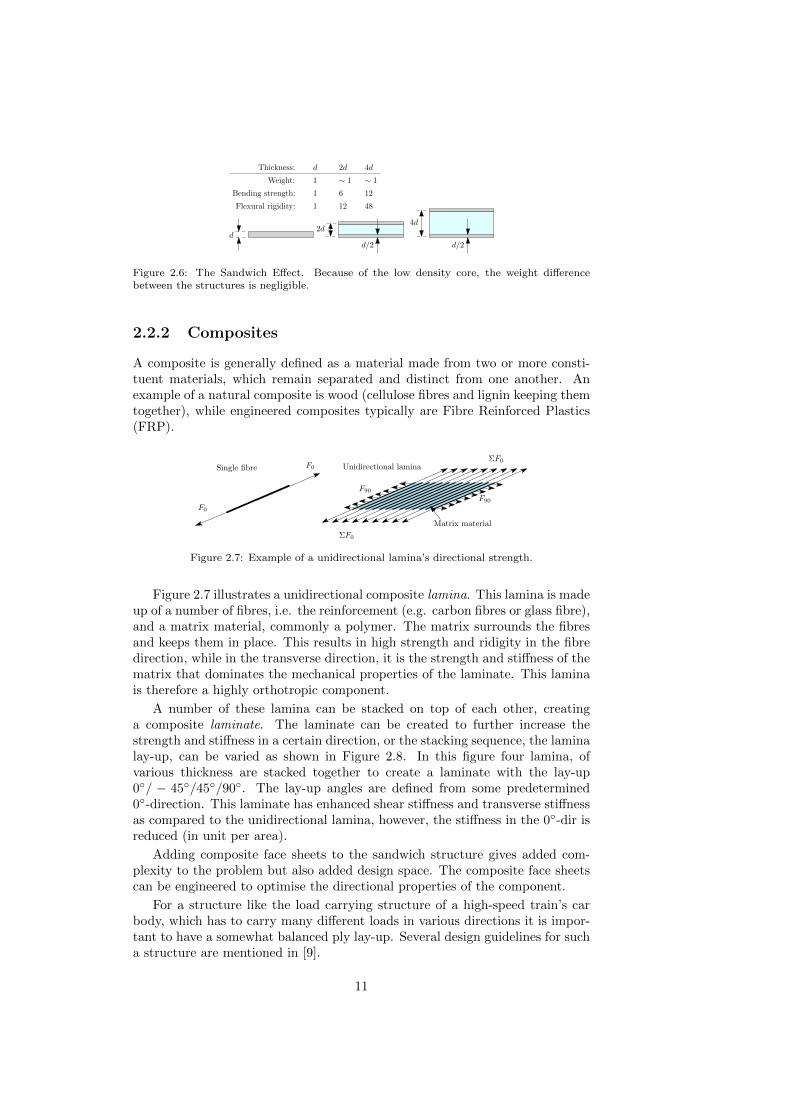
Figure 2.7: Example of a unidirectional lamina’s directional strength.
Figure 2.7 illustrates a unidirectional composite lamina. This lamina is madeup of a number of fibres, i.e. the reinforcement (e.g. carbon fibres or glass fibre),and a matrix material, commonly a polymer. The matrix surrounds the fibresand keeps them in place. This results in high strength and ridigity in the fibredirection, while in the transverse direction, it is the strength and stiffness of thematrix that dominates the mechanical properties of the laminate. This laminais therefore a highly orthotropic component.
A number of these lamina can be stacked on top of each other, creatinga composite laminate. The laminate can be created to further increase thestrength and stiffness in a certain direction, or the stacking sequence, the laminalay-up, can be varied as shown in Figure 2.8. In this figure four lamina, ofvarious thickness are stacked together to create a laminate with the lay-up0◦/ − 45◦/45◦/90◦. The lay-up angles are defined from some predetermined0◦-direction. This laminate has enhanced shear stiffness and transverse stiffnessas compared to the unidirectional lamina, however, the stiffness in the 0◦-dir isreduced (in unit per area).
Adding composite face sheets to the sandwich structure gives added com-plexity to the problem but also added design space. The composite face sheetscan be engineered to optimise the directional properties of the component.
For a structure like the load carrying structure of a high-speed train’s carbody, which has to carry many different loads in various directions it is impor-tant to have a somewhat balanced ply lay-up. Several design guidelines for sucha structure are mentioned in [9].
11

0◦
−45◦
45◦
1
2
1 2
12
2
1
90◦
four laminas
one laminate
Figure 2.8: Example of a number of lamina creating a laminate.
2.3 Sandwich structures in rail vehicles
Sandwich structures are especially popular in aerospace and marine applica-tions, e.g. passenger planes, space shuttles, satellites, pleasure boats and navyapplications. Almost half of the wetted surface area of the Boeing 757/767 ishoneycomb sandwich [10], and the first non-government funded space ship had,among other things, wings constructed in sandwich with carbon fibre reinforcedpolymer epoxy skins and honeycomb core.
In ground transportation sandwich structures can be found in cars, bussesand trains. Since the 80s front cabs of locomotives have been built with sandwichtechnology because of its high strength and good impact and energy absorptionproperties. Some examples of this are the XPT locomotives in Australia, theETR 500 locomotives in Italy, the French TGV and the Swiss locomotive 2000[10].
There are also some examples of sandwich paneled rail vehicles; e.g. Schind-ler’s wagons Revvivo, Munico and Neitec [11], the Korean Tilting Train eXpress(see Figure 2.9) [12] and Bombardier’s C20 FICAS (see Figure 2.11) [13].
2.3.1 The Korean Tilting Train eXpress (TTX)
The TTX was designed to run at 200km/h and is composed of four motorisedcars and two trailers.
To reduce the wear on the tracks the TTX upper body was constructed ofa lightweight sandwich structure with a supporting steel inner frame, cf. Fi-gure 2.10. The floor frame is manufactured from conventional stainless steelgiving a low centre of gravity thereby increasing stability during curve nego-tiation. The steel floor frame also provides increased stiffness against globalbending [12].
A preliminary design of the car body was without the supporting innerframe. However, during structural verification, the deformation of the bodyshell during vertical loading was deemed excessive.
The sandwich structure elements consist of carbon fabric/epoxy pre-pregsfor the faces and an aluminium honeycomb core. The entire car body is manu-factured as one single structure. This was accomplished by means of large scaleauto-clave. A large mould was built in which the outer face was firstly laid out.The outer face was then cured in the auto-clave. Secondly the inner frame andhoneycomb core was placed on top of the outer skin. The core and skin was
12

Figure 2.9: South Korean Tilting Train eXpress (TTX).
bonded by use of an adhesive film. After this step followed lay-up of the innerface. Lastly the entire structure was cured in the auto-clave after appropriatevacuum bagging. By constructing the entire car body as one structure weaklinks between panels are eliminated. The only remaining weak link is betweenthe upper body and floor frame [14].
The sandwich structure reduced the upper car body weight by 39% comparedto a stainless steel car body. The total weight reduction, including under frame,was 28% [12].
Inner frame of roof structure
Inner frame
Inner frame of side walls
Aluminium honeycomb sandwich
with carbon/epoxy face sheets
Carbon/epoxy
Carbon/epoxy
Aluminium
Stainless steel floor frameSkirt frame
Joining area betweencomposite bodyshell and
underframe
honeycomb
Figure 2.10: Cross-sectional view of the TTX train constructed with composite sandwichpanels and stainless steel frame [15].
13

2.3.2 C20 FICAS
The C20 FICA has been in operation in the Stockholm metro system since July16 2003. FICA is a Flat package concept, i.e. the car body is made up ofseveral modules that are bolted together. Compared to the conventional C20the FICA system has introduced large scale lightweight sandwich panels intothe load carrying structure. This has increased the aisle space with 30% andreduced the tare weight per passenger by about 8%. The C20 FICA is a 3-carunit with a total length of 46.5 m and an operating speed of 80-90 km/h.
Figure 2.11: Bombardier’s C20 FICAS metro train.
The C20 FICA body structure consists of sandwich panels in the sides, roofand floor. End beams where inserted into the sides as supports, see Figure 2.12.The sandwich panels consist of stainless steel face sheets and a Polymethacry-limide foam core.
Component Material#
Stainless steelPMI foam
1
2
3
123 Stainless steel
CoreFace sheetsInner frame
Figure 2.12: Cross-section view of typical sandwich section for the C20 FICAS.
14

Chapter 3
Light-weighting
3.1 ECO2 aspects
ECO2 stands for economy and ecology. Sustainability can only be achieved byincluding both of these aspects into the development of new technology. Belowthe ECO2 aspects of lightweight sandwich design in high-speed rail vehicles arepresented.
The large mass discrepancy between buses and trains mentioned in Sec-tion 1.1 is partly explained by the fact that trains offer a lot more space perseat in comparison to buses. The remainder is within the construction.
A rail car’s main load carrying structure, i.e. walls, roof, floor and structuralbeams, contribute to about 35-40% of the weight of the car body, the rest of theweight is stored in interior and equipment. Furthermore, wall, floor and roofpanels only contribute to about 40% of the structural weight, i.e. about 16% ofthe total weight, while the rest is stored in the framework and other structuralbeams, see Figure 3.1.
A sandwich paneled car body will, as mentioned, not only reduce the weight
16%
60%24%Non-structuralBeams/framework
Panels
Figure 3.1: Approximate weight distribution of a rail vehicle car body (bogies and drive systemexcluded).
15

of the vehicle but also reduce manufacturing complexity, by reducing the numberof parts needed and integrate several functionalities in to one single panel.
Another benefit of a sandwich paneled car body is reduced wall thickness.This was for example shown during the development of Bombardier’s metro carC20 FICAS [13]. Reducing wall thickness gives extra interior space. This mayseem insignificant, but for the C20 FICAS the wall thickness was reduced by120 mm. If the same was done on a high-speed train with 2+2 seating this couldgive an extra 6 cm between passengers, which is a significant amount of extraelbow room, increasing the comfort of train travel.
Reduced external sound, due to lower wheel-rail forces and reduced groundvibrations are also possible effects of weight reduction.
In Section 2.3, some examples of sandwich paneled rail cars are given. Eventhough these examples are very different from one another, they have at leastone similarity: they all have steel support frames to increase the stiffness orstrength of the rail vehicles.
An optimum solution, with respect to weight and simplicity, would be toremove the framework. By utilising composites’ excellent optimisation charac-teristics and looking at large scale rail car geometry, such a solution is likelypossible.
Composites offer an almost endless amount of material alternatives, whichdepending on what type is chosen, will have varying impacts on the environment.Ermolaeva et al. presented several different aspects of this with respect to hu-man health, ecosystem quality and resources [16]. However, as often concluded,the material of the lowest density will likely be the most environmental friendly[16] [17]. This is mainly due to the long product life time of rail vehicles.
3.2 Energy
Rail vehicles (here electrical) can impact the environment in many ways duringtheir life time, e.g. resource depletion, indirect greenhouse gas emissions, barriereffects in nature and vibrations. The greatest environmental impact is duringthe use phase of the rail vehicles. This is due to long life time and high mileage:rail vehicles have a life time of about 25 years during which they will travelseveral million kilometers (for long distance high speed trains this can be ashigh as 15 million kilometers). Helms and Lambrecht presented that a weightsaving of 100 kg would save around 100 GJ during the use phase of a highspeed rail vehicle [18]. A possible weight reduction of 4 tons, a probable figurefor achieving the goals set in this PhD project, assuming a linear relationship,would then result in an energy saving of 4000 GJ over the use phase.
The Swedish high-speed train X 2000 has an energy consumption of around10 kWh/train-km [19]. Assuming a travel distance of 15 million kilometersover the use phase, this equals approximately 540 000 GJ of energy consumedover the entire use phase. Approximately 25% of this energy may be coupledto the mass of the vehicle and only about 20% of the mass is within the loadcarrying structure which leaves 27 000 GJ coupled to the load carrying structureof the vehicle. A weight reduction of 30% then gives a energy saving of 8000GJ over the use phase (note: this is a rough calculation, to be compared withthe previous results by Helms [18]. For local city trains the relation betweenenergy consumption and mass reduction is around 1/2 [19], due to more frequent
16

Figure 3.2: Primary energy over whole life cycle for a high speed train car body with fourdifferent material compositions [17].
stops).
This energy saving could then be greater than the total energy consumptionduring production and raw material extraction phases [17]. This is illustratedin Figure 3.2, as well as in several other papers [16] [18] [20].
Energy consumption of rail vehicles is correlated with the physical resistancesthe vehicle must overcome during travel. These can be split into the following:
1. Rolling resistance
2. Gravitational forces
3. Acceleration forces
4. Aerodynamic drag
Resistance 1-3 above are all dependent on the mass of the rail vehicle. Theaerodynamic resistance is dependent on the shape and length of the rail vehicleand is almost proportional to the square of speed. Weight reduction of rail ve-hicles thus results in lowering of the first three resistances listed above. Thereis, furthermore, also a lot being done to reduce the aerodynamic drag of trains,especially for high speed trains. This, together with increasing efficiency andutilising more and more energy efficient breaking results in that new trains run-ning at greater speeds generally have reduced energy consumption as comparedto older, slower, trains [19].
By 2050 energy per passenger kilometer for long distance car travel and airtravel could be lowered to 0.12 and 0.32 kWh respectively [21]. Long distancerail transport is already today below these figures and could by 2050 be aslow as 0.05 kWh/passenger-km [21], probably even lower, as some trains todayalready have reached this level, cf. the ”Green Train” research project [22].Weight reduction is one step on the way to reaching these goals [19].
17

3.3 Green house gas emissions
It is not always clear how to calculate the true environmental impact of weightreduction for rail vehicles. Compared to the majority of other transportationmodes, electrical trains do not carry their energy supply with them during tra-vel. This obscures the benefits of weight reduction with regard to emissions ofgreenhouse gases since this directly depends on the energy mix used in the re-gion. Some argue that rail vehicles should be accountable for greenhouse gasesequivalent to that from generating electricity from coal power plants, from thepoint of view that if the trains were not running it would be possible to reducethe electricity needed from these plants by the amount used by rail transpor-tation. Others see this as an unfair comparison since trains run regardless ofif coal power is imported/produced or not. Either way rail transportation canreduce their energy consumption with more effective and lighter vehicles andthus directly or indirectly reduce greenhouse gas emissions.
3.4 Effective rail transportation
Increased rail travel will not reduce the impact on the environment if it doesnot replace more energy intensive modes of transport.
Today the cost of a domestic flight in Sweden, between the largest cities, isin the same price range as train travel. For trains to compete with air travelthey need to provide the right comfort, at the right cost, as well as providingacceptable travel times.
The Swedish high speed train X2000 is generally faster than airline travelfor distances up to about 300 km, door to door. Compared to car travel, traintravel is usually faster for distances above 150 km.
In the near future rail transportation will likely be charged in relation tohow track ”friendly” the vehicles are, i.e. if they exert large track forces andlarge amounts of track wear or not. By lowering the weight of rail vehicles andthus lowering axle loads, train speeds may be increased, even on curved tracks,without increasing the wheel-rail forces. Already today trains are required notto exceed a certain maximum axle load in order to run at certain speeds. This isespecially important when the number of axles are minimised, e.g. in articulatedtrains.
Higher speeds would likely make train travel more appealing and hopefullyshift transportation from for example long distance car travel, domestic flightand perhaps even some international air travel to rail transportation. It should,however, be mentioned that light-weighting is currently not critical for the de-velopment towards higher speeds. Track deterioration on the other hand, whichincreases with higher speeds, is correlated to the weight of the vehicle.
Alternatively, weight reduction and widened inner space, achievable withthinner walls, could allow for increased payload at the same performance le-vel. Thinner walls may be possible with the multi-functionality of sandwichpanels. This could enhance profits and eventually lower ticket prices makingtrain travel more reasonable not only from an environmental view but also froman economical.
Both alternatives increase the effectiveness of the transportation mode byincreasing number of seats/passengers per time and distance effectively lowering
18

costs per payload-kilometer. This makes better use of the crew, increasingworking kilometers. The same goes for other costs such as maintenance, energy,cleaning, infrastructure, etc. The reduced energy consumption can, of course,alone reduce costs and thus also enhance profits and/or lower ticket prices.
A modern attractive train is also highly valued by the customer and fromexperience will increase occupancy [23]. Use of composites in the body structureof the rail car may allow a new, more pleasing, aesthetic design further improvingrail vehicles stand in the public transportation market.
A shift to more rail transportation from road and air travel will give anational economic gain since heavy road traffic and flight are not always taxed,or feed in proportion to their environmental impacts. Shorter travel times, whichwould be achievable with higher speeds, are also seen as very positive from apublic economic view, this is due to the fact that travelers highly value time,and a reduction of travel time is valued proportional to a significant fraction ofticket prices [23].
3.5 Downsizing
Weight reduction can also set off a weight saving spiral or downsizing of compo-nents and equipment which can give an additional environmental saving hard torealise from just studying weight saving. Helms et al. claim that fuel savings per100 km and 100 kg where four times higher when a rear axle transmission wasadjusted to match the new power to weight ratio of a road vehicle after weightreduction than compared with only the lowered weight [18]. A downsizing spiralwould undoubtedly also have several other economical advantages, e.g. simplerbrakes, dampers, traction equipment, etc., can be utilised to achieve the sameperformance level.
As an example we can look at the brakes of a rail vehicle. Future trainswill likely more and more rely solely on electrical brakes. Today a mixture ofelectrical and mechanical brakes are used to achieve a sufficient deceleration. Infuture trains, both to reduce net energy consumption and brake maintenance,the mechanical brakes may be replaced (or at least reduced) by increasing thepower of the electrical brakes. Since deceleration requirements are often stricterthan acceleration requirements this means up-sizing the electrical motors. Re-ducing the weight of the rail vehicle directly lowers the amount of force neededfor a certain deceleration, i.e. motor power does not have to be increased to thesame extent.
3.6 Concerns
There are, however, a few aspects that may rather have a negative effect whenreducing the weight of the car body and introducing composites into the loadcarrying structure.
A lighter rail vehicle is easier to push off the track than a heavier rail vehicle.Cross wind safety is therefore affected negatively when the car weight is reduced.This issue must be considered carefully to avoid the need for ballasting of theend cars.
19

Crash safety and energy absorption is another concern when using compo-sites. Metals, and especially stainless steel, are well known in the industry andhave good energy absorbing properties. Composite sandwich structures havea wide variety of failure modes, where only some may give sufficient energyabsorption properties. The difficulty lies in finding which mode will fail first,and how to create a structure that will consistently fail in the same manner.Furthermore the analysis methods available for composite structure are not asevolved as those for metal structures.
Composites have exceptionally good strength to weight qualities, but thisis only one advantage with composites. Generally, they also have good corro-sion resistance compared with other materials, which is of course an advantageduring the long life time of rail vehicles, perhaps resulting in less maintenanceor less replacements of components. On the other hand this feature results inrecyclability issues. There are, however, a lot of natural fiber composites thathave been and still are in use, e.g. hemp fibers. These natural fibers haveseveral advantages with respect to weight saving, recyclability, material price,etc. However, as the name suggests, these are natural materials, which resultsin poor consistency in quality compared to engineered materials. Furthermorethe natural fibers cannot match other properties of the toughest engineered ma-terials, for example: stiffness, strength, fire properties, water absorption andothers.
Even though a lot of composites end up as land fill; some may be consideredun-recyclable, and some are simply cheaper to new-produce, the increased inter-est in these materials will continue to put high pressure on solving recyclabilityissues.
20

3.7 ECO2 Overview
Table 3.1 gives a quick overview of some of the economical and ecological benefitsthat are possible by introducing sandwich panels into the load carrying structureof the car body.
Table 3.1: Example summary of benefits and concerns of a Sandwich car body. ECO2 benefitsare both Economy benefits, interpreted as beneficial for the operator, and Ecology benefits,beneficial for the ecosystem in general. Results shown as -/+ are uncertain or may varydepending on choice of construction.
Change Outcome ECO2 Safety
Lower weight
{ Reduced energy consumption +Reduced external sound +Downsizing of componentsa +Reduced track deterioration + +Indirectly reduced GHG emissions +Crosswind sensitivity -
Thinner walls{ Increased payload capacity +
Increased comfort +
Fewer parts{ Easier manufacturing +
Attractive design +
”New” materials
{ Crash safety -/+Recyclability issues -/+Fire safety -/+
a which may set off a downsizing-spiral effect.
21

22

Chapter 4
Summary
4.1 Discussion
The potential scope of this project is wide, which is in itself an obstacle: how toobjectively define what areas of research are the most important given the timeframe of a PhD thesis. Should focus be put on performance, multi-functionality,ecological or economical aspects? All parts fit into the same puzzle, however,focusing on one alters the shape of the others.
Material choice, for example, will in the end be a trade-off between me-chanical, environmental and economical properties. Some of these are easy toquantify, for instance the mechanical properties: the rail car must achieve suffi-cient strength and stiffness in a large amount of different scenarios to be up tostandard. Others are tougher to get an objective understanding about: whatdegree of non-recyclability can be compensated by a given weight reduction?Which effect is considered most significant/environmentally friendly? Further-more, can a significant cost reduction compensate a more unfriendly material,and where is that line drawn?
For the environmental effects different indicator(s) [24], e.g. the Eco-99indicator used in [25], or the corresponding lower level indicators, give an easyoverview of the environmental impact of different material choices by illustratingit as single figure(s). However, this simplicity comes at the cost of uncertainty.Furthermore, several of the indicators and values seem to be highly suggestible,and different results may therefore be achieved when using different indicators.
The process of finding an optimum solution to the above questions will likelybe a minimisation problem with weight as the objective function (seeing asreduced weight will likely give the largest environmental and economical gain),as well as an iterative process if large scale geometric modification of the railcar will be acceptable.
At the same time production costs should be taken under consideration fordifferent alternatives to ensure that a realistic solution is ultimately found.
4.2 Present work
The work performed so far has concentrated on minimising the mass of thevehicle while achieving sufficient stiffness. An early goal was a 30% weight re-
23

duction of the load carrying structure of the car body by replacing this structurewith load carrying sandwich panels, cf. Figure 4.1.
Original load carrying structure
Load carrying sandwich panel
structural beams
structural sheet metal
Figure 4.1: Concept of structure replacement.
Both metallic and composite face sheets have been studied, with various corematerials.
From the literature study performed in the beginning of this project [2], oneof the main issues with load carrying sandwich panels was insufficient globalstiffness of the car body. The following papers therefore have a large focus onachieving sufficient stiffness.
A Finite Element model of a Regina type car body was used as a startingpoint (courtesy of Bombardier Transportation).
The Regina car body is what is called a lightweight steel construction, withan extensive, ring-like, steel framework stiffening the cross-section of the carbody.
Outer metal sheets carry normal and shear loads during bending of the carbody and during coupler loading. These sheets are stabilised by the frameworkas well as additional stringers.
Large sole bars are used to enhance the vertical bending stiffness as well ascarry the normal stress during loading over the couplers.
The original model was very highly detailed, and contained over 1.2 millionelements. As a result, modal analysis took over 48 h on a standard calculationmachine.
Initial work was focused on simplifying the model into a more manageablesize of about 14 000 elements, to enable fast parameter studies of the car body.This required an increase in element size. One restriction on element size wasthe corrugated sheets in the roof and floor structure, which have a geometrysuch that requires rather small elements. This is the background to PaperA, where orthotropic modeling techniques for corrugated sheets are studied inFinite Element Analysis.
From the results of Paper A, sandwich panels have been derived from re-quirements based on the mechanical properties of the corrugated sheets. Thesandwich panels are designed to replace the corrugated sheets while obtainingthe same or increased performance. This is the background to Paper B, wherea 600-700 kg weight reduction of these specific panels was achieved.
The global eigen frequencies of the car body have been used as the over allperformance measure with respect to car body stiffness and dynamic characte-ristics.
In Paper C a semi automated method of deriving completely self suppor-ting sandwich panels for the car body cross-section is presented, based on theknowledge gained from earlier work. A total weight reduction of over 30% was
24

achieved for the load carrying structure of the rail car. Commercial optimisa-tion software was used to minimise the weight of the structure, giving a generaland applicable method for reducing the weight of load carrying structures.
4.3 Future work
Currently only mechanical properties, especially stiffness, have been in focus.The toughest load cases of the prEN 12663 norm [3] have been tested, withsatisfactory results. Stress levels were well below the strength of the derivedpanels. However, to truly evaluate the strength a detailed, 3D model, of theentire sandwich car body should be constructed.
The derived car body should also be evaluated from a comfort perspectiveby performing a full comfort evaluation in SIMPACK and comparing this withthe original car body.
In the current design, the idea is to lead the coupler forces through the floorstructure, instead of through the sole bars as in the original structure. Oneissue here is how to introduce these large forces into the sandwich floor, whattype of connections are possible?
Furthermore, in the next phase of the project, acoustic and thermal requi-rements for the car body structure should be evaluated, and compared to thecurrent sandwich structure. Based on the results from such a comparison, thenext step would be to optimise the current solution to fulfill these requirements.This may increase the mass of the current sandwich panels, however, since theythen can replace other components, beside the load carrying structure, the totalmass will more likely be reduced further. One example is the ”floating” floorstructure in the vehicle, which fulfills an acoustic function and has a rathersubstantial mass. Can this be integrated into the floor sandwich panel?
Another interesting, multi-functionality, of the sandwich panels would be tostudy if the inner face could be designed to fulfill the inner lining requirements.
Eventually a car body design should be chosen, this could include a numberof alterations, and optimisation to the current structure, e.g.:
• Window pillar placement, thickness and shape optimisation
• Modular study of door section
• Optimisation of floor-wall connection
Furthermore a general cost estimation (cost per kilogram car body), maybe possible as well as a wheel wear and energy savings evaluation based on themass reduction of the vehicle.
A simple LCC evaluation, perhaps based on commercial software, shouldalso be performed.
25

26

Bibliography
[1] P. Wennhage, Structural – Acoustic Optimization of Sandwich Panels. PhDthesis, Department of Aeronautics, KTH, Stockholm, Sweden, 2001.
[2] D. Wennberg, “A light weight car body for high-speed trains - literaturestudy,” tech. rep., KTH, Stockholm, Sweden, 2010.
[3] CEN, “Railway applications - structural requirements of railway vehiclebodies - part 1: railway vehicles other than freight wagons,” prEn 12663-1,May 2007.
[4] P. Freiholtz, Vertical comfort study of the Green Train. PhD thesis, Masterof Science Thesis, KTH Industrial Engineering and Management, Depart-ment of Solid Mechanics, Stockholm, May 2008.
[5] C. J. Cameron, Design of Multifunctional Body Panels in Automotive Ap-plications - Licentiate Thesis. 2009.
[6] C. J. Cameron, Design of Multifunctional Body Panels for. Doctoral thesisin lightweight structures, Department of Aeronautics, KTH, Stockholm,Sweden, 2011.
[7] R. Boeman and N. Johnson, “Development of a cost competitive, compo-site intensive, body-in-white.” Automotive Composites Consortium focalprojekt, 2002.
[8] D. Zenkert, An Introduction to Sandwich Construction. Solihull, UK: En-gineering Materials Advisory Services Ltd., 1995.
[9] J.-S. Kim, N.-P. Kim, and S.-H. Han, “Optimal stiffness design of compo-site laminates for a train carbody be an expert system and enumerationmethod,” Composite Structures, 2004.
[10] J. R. Vinson, ed., Sandwich structures: Past, Present and Future, 2005.
[11] U. Author, “Schindler is on track with frp trains,” Reinforced Plastics,vol. 39, pp. 28–32, November 1995.
[12] S. I. Seo, J. S. Kim, and S. H. Cho, “Development of a hybrid compositebodyshell for tilting trains,” Journal of Rail and Rapid Transit (IMechE),vol. 222, no. 222, pp. 1–14, 2008.
[13] M. Knutton, “Bombardier develops ”game-changing” technology,” Inter-national Railway Journal. FindArticles.com., July 2010.
27

[14] K. Soo-Hyun, K. Sang-Guk, K. Chun-Gon, and S. Kwang-Bok, “Anaysisof the composite structure of tilting train express(ttx),” ICCM15, Republicof South Africa, 2005.
[15] J.-S. Kim, S.-J. Lee, and K.-B. Shin, “Manufacturing and structural safetyevaluation of a composite train carbody,” Composite Structures, no. 78,pp. 468–476, 2007.
[16] N. Ermolaeva, M. Castro, and P. Kandachar, “Material selection for anautomotive structure by integrating structural optimization with environ-mental impact assessment,” Materials and design 25, pp. 689–698, 2004.
[17] I. Blanc, P. Schwab, M. Gomez, O. Jolliet, B. Ecabert, M. Wakeman,J.-A. Manson, and D. Emery, “Towards the eco-design of a tilting trainin korea: Applying life cycle assessment to design alternatives,” SMIAGeneva, September 2005.
[18] H. Helms and U. Lambrecht, “The potential contribution of light-weightingto reduce transport energy consumption,” International Journal of LifeCycle Assessment, pp. 58–64, 2007.
[19] E. Andersson, M. Berg, O. Froidh, and B.-L. Nelldal, “Rail passenger trans-port, techno-economic analysis of energy and green-house gas reductions,”TOSCA: Work Package 3 (WP3), Internal report, 2010.
[20] J. Duflou, J. D. Moor, I. Verpoest, and W. Dewulf, “Environmental impactanalysis of composite use in car manufacturing,” Manufacturing Techno-logy, no. 58, pp. 9–12, 2009.
[21] J. Akerman and M. Hojer, “How much tranport can the climate stand?sweden on a sustainable path in 2050,” Energy Policy 34, pp. 1944–1957,2006.
[22] P. Lukaszewics and E. Anderson, “Green train energy consumption, esti-mations on high-speed rail operation,” KTH Railway Group, ISBN: 978-91-7415-257-9, Stockholm, 2009.
[23] E. Andersson and M. Berg, Spartrafiksystem och sparfordon, Del 1:Spartrafiksystem. Railway Group KTH, Div. of Railway Technology, Dep.Of Aeronautical & Vehicle Eng, the Royal Institute of Technology, 2007.
[24] B. Nessa, E. Urbel-Piirsalua, S. Anderbergd, and L. Olssona, “Categorisingtools for sustainability assessment,” Ecological Economics, pp. 498–508,2007.
[25] N. S. Ermolaeva, M. B. Castro, and P. V. Kandachar, “Materials selectionfor an automotive structure by integrating structural optimization withenvironmental impact assessment,” Materials and Design, no. 25, pp. 689–698, 2004.
28

Chapter 5
Appended papers A-C
29