lighting/electrical 25 lisa bornemann · independence visitor center philadelphia, pa theater...
TRANSCRIPT
INDEPENDENCE VISITOR CENTER
PHILADELPHIA, PA
THEATER LIGHTING
Lighting/Electrical 25 Lisa Bornemann
THEATER LIGHTING
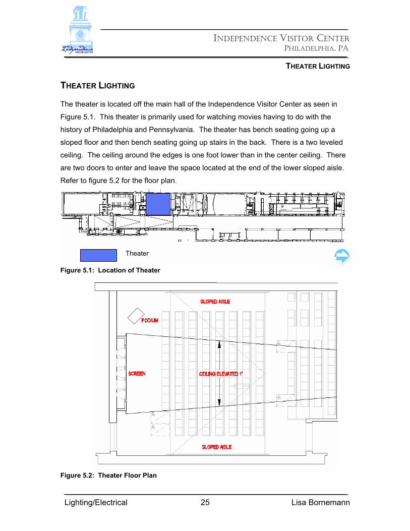
The theater is located off the main hall of the Independence Visitor Center as seen in
Figure 5.1. This theater is primarily used for watching movies having to do with the
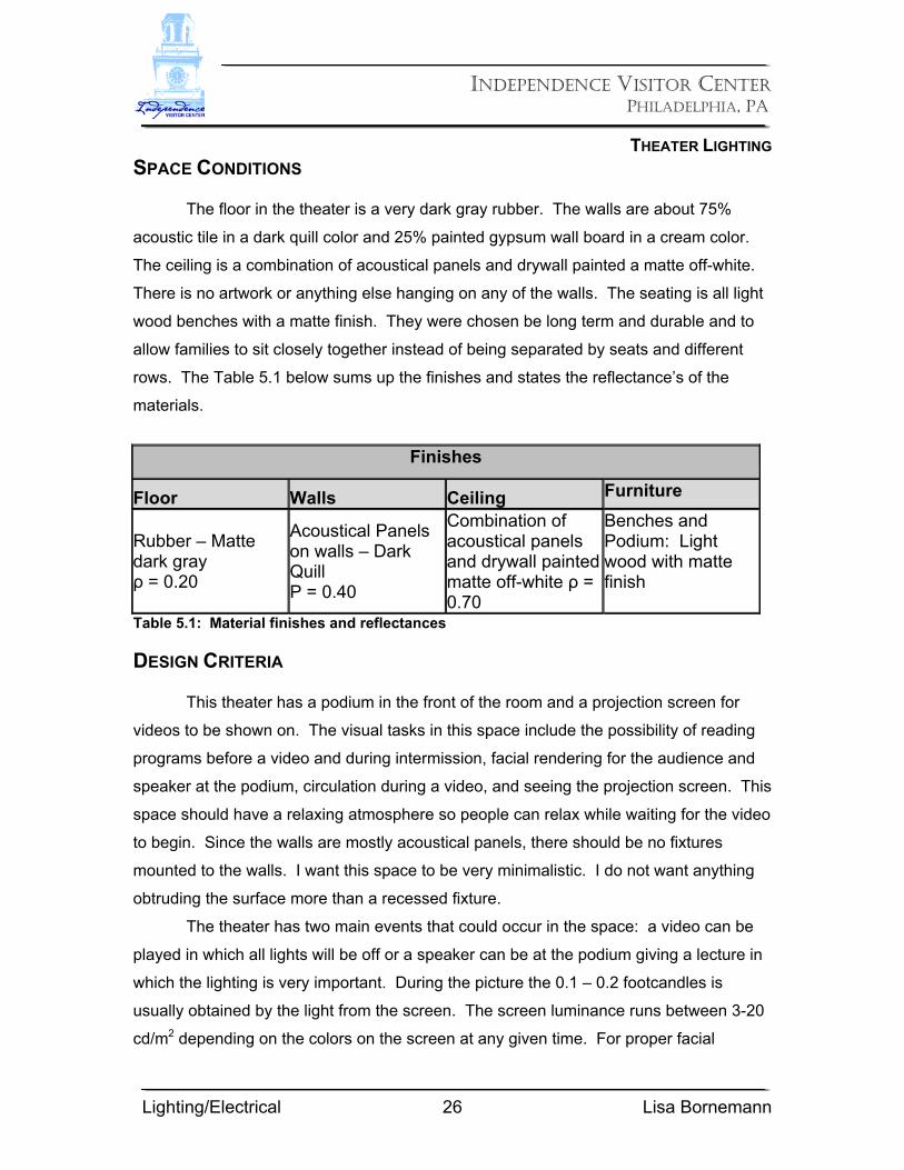
history of Philadelphia and Pennsylvania. The theater has bench seating going up a
sloped floor and then bench seating going up stairs in the back. There is a two leveled
ceiling. The ceiling around the edges is one foot lower than in the center ceiling. There
are two doors to enter and leave the space located at the end of the lower sloped aisle.
Refer to figure 5.2 for the floor plan.
Figure 5.1: Location of Theater
Figure 5.2: Theater Floor Plan
Theater
INDEPENDENCE VISITOR CENTER
PHILADELPHIA, PA
THEATER LIGHTING
Lighting/Electrical 26 Lisa Bornemann
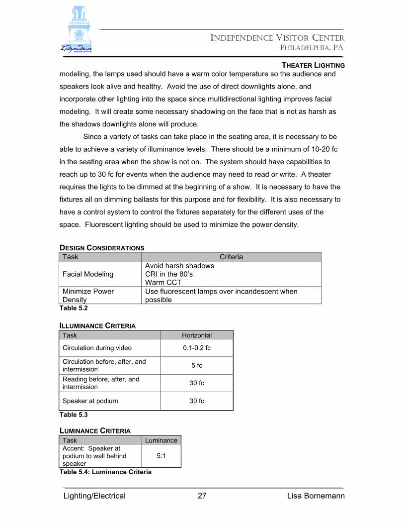
SPACE CONDITIONS
The floor in the theater is a very dark gray rubber. The walls are about 75%
acoustic tile in a dark quill color and 25% painted gypsum wall board in a cream color.
The ceiling is a combination of acoustical panels and drywall painted a matte off-white.
There is no artwork or anything else hanging on any of the walls. The seating is all light
wood benches with a matte finish. They were chosen be long term and durable and to
allow families to sit closely together instead of being separated by seats and different
rows. The Table 5.1 below sums up the finishes and states the reflectance’s of the
materials.
Finishes
Floor Walls Ceiling Furniture
Rubber – Matte dark gray ρ = 0.20
Acoustical Panels on walls – Dark Quill Ρ = 0.40
Combination of acoustical panels and drywall painted matte off-white ρ = 0.70
Benches and Podium: Light wood with matte finish
Table 5.1: Material finishes and reflectances DESIGN CRITERIA
This theater has a podium in the front of the room and a projection screen for
videos to be shown on. The visual tasks in this space include the possibility of reading
programs before a video and during intermission, facial rendering for the audience and
speaker at the podium, circulation during a video, and seeing the projection screen. This
space should have a relaxing atmosphere so people can relax while waiting for the video
to begin. Since the walls are mostly acoustical panels, there should be no fixtures
mounted to the walls. I want this space to be very minimalistic. I do not want anything
obtruding the surface more than a recessed fixture.
The theater has two main events that could occur in the space: a video can be
played in which all lights will be off or a speaker can be at the podium giving a lecture in
which the lighting is very important. During the picture the 0.1 – 0.2 footcandles is
usually obtained by the light from the screen. The screen luminance runs between 3-20
cd/m2 depending on the colors on the screen at any given time. For proper facial
INDEPENDENCE VISITOR CENTER
PHILADELPHIA, PA
THEATER LIGHTING
Lighting/Electrical 27 Lisa Bornemann
modeling, the lamps used should have a warm color temperature so the audience and
speakers look alive and healthy. Avoid the use of direct downlights alone, and
incorporate other lighting into the space since multidirectional lighting improves facial
modeling. It will create some necessary shadowing on the face that is not as harsh as
the shadows downlights alone will produce.
Since a variety of tasks can take place in the seating area, it is necessary to be
able to achieve a variety of illuminance levels. There should be a minimum of 10-20 fc
in the seating area when the show is not on. The system should have capabilities to
reach up to 30 fc for events when the audience may need to read or write. A theater
requires the lights to be dimmed at the beginning of a show. It is necessary to have the
fixtures all on dimming ballasts for this purpose and for flexibility. It is also necessary to
have a control system to control the fixtures separately for the different uses of the
space. Fluorescent lighting should be used to minimize the power density.
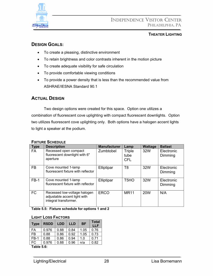
DESIGN CONSIDERATIONS Task Criteria
Facial Modeling Avoid harsh shadows CRI in the 80’s Warm CCT
Minimize Power Density
Use fluorescent lamps over incandescent when possible
Table 5.2 ILLUMINANCE CRITERIA Task Horizontal
Circulation during video 0.1-0.2 fc
Circulation before, after, and intermission 5 fc
Reading before, after, and intermission 30 fc
Speaker at podium 30 fc
Table 5.3 LUMINANCE CRITERIA Task LuminanceAccent: Speaker at podium to wall behind speaker
5:1
Table 5.4: Luminance Criteria
INDEPENDENCE VISITOR CENTER
PHILADELPHIA, PA
THEATER LIGHTING
Lighting/Electrical 28 Lisa Bornemann
DESIGN GOALS:
• To create a pleasing, distinctive environment
• To retain brightness and color contrasts inherent in the motion picture
• To create adequate visibility for safe circulation
• To provide comfortable viewing conditions
• To provide a power density that is less than the recommended value from
ASHRAE/IESNA Standard 90.1
ACTUAL DESIGN
Two design options were created for this space. Option one utilizes a
combination of fluorescent cove uplighting with compact fluorescent downlights. Option
two utilizes fluorescent cove uplighting only. Both options have a halogen accent lights
to light a speaker at the podium.
FIXTURE SCHEDULE Type Description Manufacturer Lamp Wattage Ballast FA Recessed open compact
fluorescent downlight with 6" aperture
Zumbtobel Triple tube CFL
32W Electronic Dimming
FB Cove mounted 1-lamp fluorescent fixture with reflector
Elliptipar T8 32W Electronic Dimming
FB-1 Cove mounted 1-lamp fluorescent fixture with reflector
Elliptipar T5HO 32W Electronic Dimming
FC Recessed low-voltage halogen adjustable accent light with integral transformer.
ERCO MR11 20W N/A
Table 5.5: Fixture schedule for options 1 and 2 LIGHT LOSS FACTORS Type RSDD LDD LLD BF Total
LLF FA 0.976 0.88 0.84 1.05 0.76 FB 0.88 0.86 0.92 1.05 0.73 FB-1 0.88 0.86 0.94 1.0 0.71 FC 0.976 0.88 0.96 n/a 0.82 Table 5.6:

INDEPENDENCE VISITOR CENTER
PHILADELPHIA, PA
THEATER LIGHTING
Lighting/Electrical 29 Lisa Bornemann
OPTION 1:
INDEPENDENCE VISITOR CENTER
PHILADELPHIA, PA
THEATER LIGHTING
Lighting/Electrical 30 Lisa Bornemann
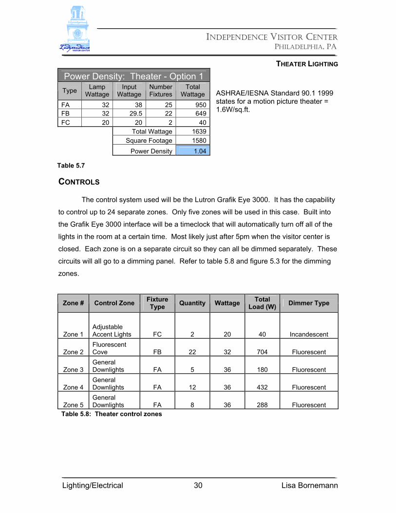
ASHRAE/IESNA Standard 90.1 1999 states for a motion picture theater = 1.6W/sq.ft.
CONTROLS The control system used will be the Lutron Grafik Eye 3000. It has the capability
to control up to 24 separate zones. Only five zones will be used in this case. Built into
the Grafik Eye 3000 interface will be a timeclock that will automatically turn off all of the
lights in the room at a certain time. Most likely just after 5pm when the visitor center is
closed. Each zone is on a separate circuit so they can all be dimmed separately. These
circuits will all go to a dimming panel. Refer to table 5.8 and figure 5.3 for the dimming
zones.
Zone # Control Zone Fixture Type Quantity Wattage Total
Load (W) Dimmer Type
Zone 1 Adjustable Accent Lights FC 2 20 40 Incandescent
Zone 2 Fluorescent Cove FB 22 32 704 Fluorescent
Zone 3 General Downlights FA 5 36 180 Fluorescent
Zone 4 General Downlights FA 12 36 432 Fluorescent
Zone 5 General Downlights FA 8 36 288 Fluorescent
Table 5.8: Theater control zones
Power Density: Theater - Option 1 Type Lamp
Wattage Input
Wattage Number Fixtures
Total Wattage
FA 32 38 25 950FB 32 29.5 22 649FC 20 20 2 40 Total Wattage 1639 Square Footage 1580 Power Density 1.04
Table 5.7
INDEPENDENCE VISITOR CENTER
PHILADELPHIA, PA
THEATER LIGHTING
Lighting/Electrical 31 Lisa Bornemann
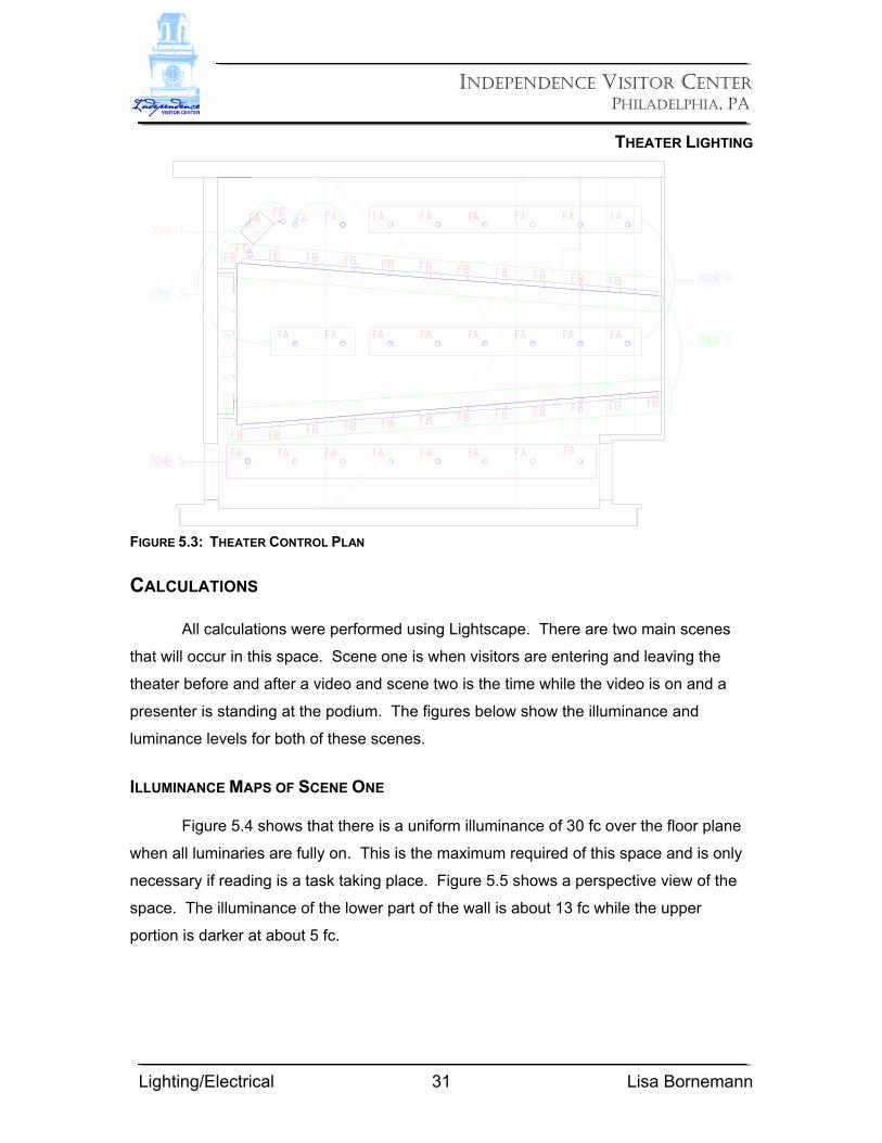
FIGURE 5.3: THEATER CONTROL PLAN CALCULATIONS All calculations were performed using Lightscape. There are two main scenes
that will occur in this space. Scene one is when visitors are entering and leaving the
theater before and after a video and scene two is the time while the video is on and a
presenter is standing at the podium. The figures below show the illuminance and
luminance levels for both of these scenes.
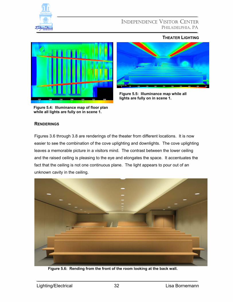
ILLUMINANCE MAPS OF SCENE ONE Figure 5.4 shows that there is a uniform illuminance of 30 fc over the floor plane
when all luminaries are fully on. This is the maximum required of this space and is only
necessary if reading is a task taking place. Figure 5.5 shows a perspective view of the
space. The illuminance of the lower part of the wall is about 13 fc while the upper
portion is darker at about 5 fc.
INDEPENDENCE VISITOR CENTER
PHILADELPHIA, PA
THEATER LIGHTING
Lighting/Electrical 32 Lisa Bornemann
RENDERINGS
Figures 3.6 through 3.8 are renderings of the theater from different locations. It is now
easier to see the combination of the cove uplighting and downlights. The cove uplighting
leaves a memorable picture in a visitors mind. The contrast between the lower ceiling
and the raised ceiling is pleasing to the eye and elongates the space. It accentuates the
fact that the ceiling is not one continuous plane. The light appears to pour out of an
unknown cavity in the ceiling.
Figure 5.6: Rending from the front of the room looking at the back wall.
Figure 5.4: Illuminance map of floor plan while all lights are fully on in scene 1.
Figure 5.5: Illuminance map while all lights are fully on in scene 1.

INDEPENDENCE VISITOR CENTER
PHILADELPHIA, PA
THEATER LIGHTING
Lighting/Electrical 33 Lisa Bornemann
Figure 5.7: Rending from the front side of the room looking at the back side.
Figure 5.8: Rending from the back of the room looking at the front screen. ILLUMINANCE AND LUMINANCE MAPS DURING SCENE TWO Scene Two has accent lights aimed on the speaker and the row of downlights dimmed to
20% between the two exit doors. The video is also on providing additional light that was
not calculated into the lightscape renderings.
INDEPENDENCE VISITOR CENTER
PHILADELPHIA, PA
THEATER LIGHTING
Lighting/Electrical 34 Lisa Bornemann
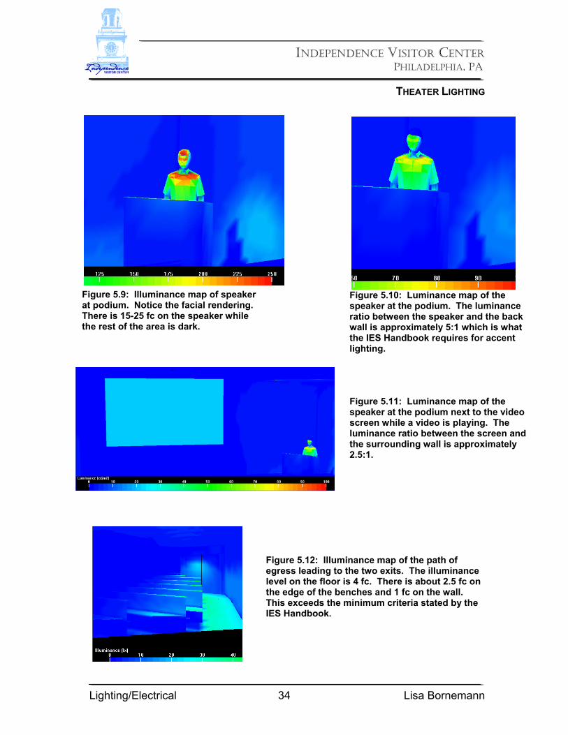
Figure 5.9: Illuminance map of speaker at podium. Notice the facial rendering. There is 15-25 fc on the speaker while the rest of the area is dark.
Figure 5.10: Luminance map of the speaker at the podium. The luminance ratio between the speaker and the back wall is approximately 5:1 which is what the IES Handbook requires for accent lighting.
Figure 5.11: Luminance map of the speaker at the podium next to the video screen while a video is playing. The luminance ratio between the screen and the surrounding wall is approximately 2.5:1.
Figure 5.12: Illuminance map of the path of egress leading to the two exits. The illuminance level on the floor is 4 fc. There is about 2.5 fc on the edge of the benches and 1 fc on the wall. This exceeds the minimum criteria stated by the IES Handbook.
INDEPENDENCE VISITOR CENTER
PHILADELPHIA, PA
THEATER LIGHTING
Lighting/Electrical 35 Lisa Bornemann
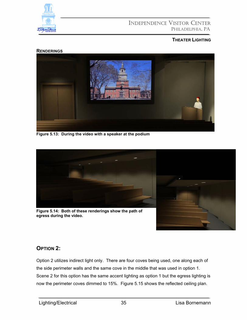
RENDERINGS
Figure 5.13: During the video with a speaker at the podium
Figure 5.14: Both of these renderings show the path of egress during the video. OPTION 2: Option 2 utilizes indirect light only. There are four coves being used, one along each of
the side perimeter walls and the same cove in the middle that was used in option 1.
Scene 2 for this option has the same accent lighting as option 1 but the egress lighting is
now the perimeter coves dimmed to 15%. Figure 5.15 shows the reflected ceiling plan.
INDEPENDENCE VISITOR CENTER
PHILADELPHIA, PA
THEATER LIGHTING
Lighting/Electrical 36 Lisa Bornemann
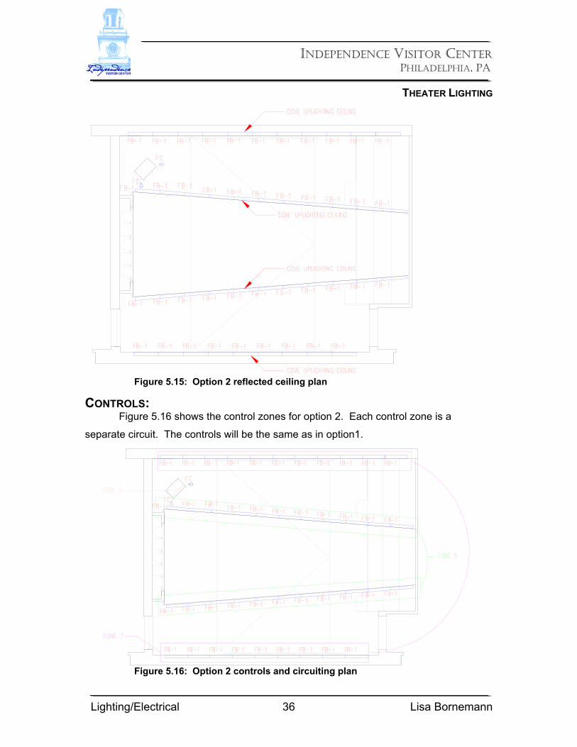
CONTROLS: Figure 5.16 shows the control zones for option 2. Each control zone is a
separate circuit. The controls will be the same as in option1.
Figure 5.16: Option 2 controls and circuiting plan
Figure 5.15: Option 2 reflected ceiling plan
INDEPENDENCE VISITOR CENTER
PHILADELPHIA, PA
THEATER LIGHTING
Lighting/Electrical 37 Lisa Bornemann
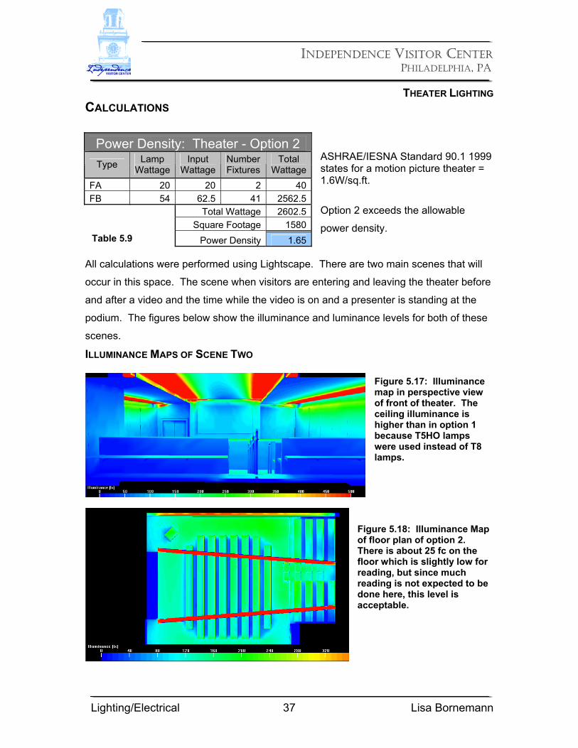
CALCULATIONS
ASHRAE/IESNA Standard 90.1 1999 states for a motion picture theater = 1.6W/sq.ft.
Option 2 exceeds the allowable
power density.
All calculations were performed using Lightscape. There are two main scenes that will
occur in this space. The scene when visitors are entering and leaving the theater before
and after a video and the time while the video is on and a presenter is standing at the
podium. The figures below show the illuminance and luminance levels for both of these
scenes.
ILLUMINANCE MAPS OF SCENE TWO Figure 5.17: Illuminance map in perspective view of front of theater. The ceiling illuminance is higher than in option 1 because T5HO lamps were used instead of T8 lamps.
Figure 5.18: Illuminance Map of floor plan of option 2. There is about 25 fc on the floor which is slightly low for reading, but since much reading is not expected to be done here, this level is acceptable.
Power Density: Theater - Option 2 Type Lamp
Wattage Input
Wattage Number Fixtures
Total Wattage
FA 20 20 2 40FB 54 62.5 41 2562.5 Total Wattage 2602.5 Square Footage 1580 Power Density 1.65Table 5.9

INDEPENDENCE VISITOR CENTER
PHILADELPHIA, PA
THEATER LIGHTING
Lighting/Electrical 38 Lisa Bornemann
RENDERINGS Figures 5.19 through 5.20 are renderings of the theater from different locations. It is now
easier to see what the theater looks like with uplighting only. There is a cove along each
side wall with a fixture uplighting the ceiling on the sides as well as the cove through the
middle. This lighting scheme leaves all fixtures hidden. There is a completely
uninterrupted ceiling plane. The contrast between the wall sides of the ceiling and the
inner edges creates an interesting pattern. Again this accentuates the fact that the
ceiling is not one continuous plane. The light appears to pour out of an unknown cavity
in the ceiling.
Figure 5.19: Rendering of option 2 from front of theater looking at back wall.
Figure 5.20: Rendering of option 2 from back of theater looking at front wall.
INDEPENDENCE VISITOR CENTER
PHILADELPHIA, PA
THEATER LIGHTING
Lighting/Electrical 39 Lisa Bornemann
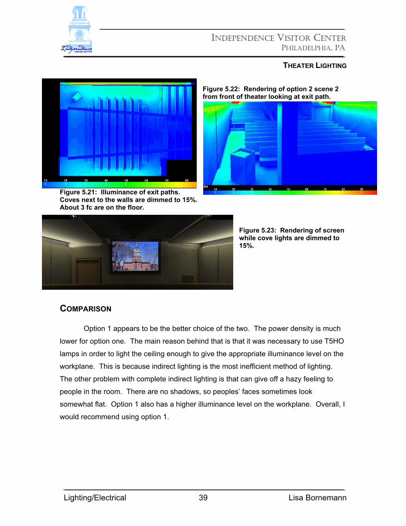
Figure 5.22: Rendering of option 2 scene 2 from front of theater looking at exit path.
Figure 5.21: Illuminance of exit paths. Coves next to the walls are dimmed to 15%. About 3 fc are on the floor.
Figure 5.23: Rendering of screen while cove lights are dimmed to 15%.
COMPARISON Option 1 appears to be the better choice of the two. The power density is much
lower for option one. The main reason behind that is that it was necessary to use T5HO
lamps in order to light the ceiling enough to give the appropriate illuminance level on the
workplane. This is because indirect lighting is the most inefficient method of lighting.
The other problem with complete indirect lighting is that can give off a hazy feeling to
people in the room. There are no shadows, so peoples’ faces sometimes look
somewhat flat. Option 1 also has a higher illuminance level on the workplane. Overall, I
would recommend using option 1.