lightning strikes - techniques and requirements for a well
TRANSCRIPT

Lightning Strikes - Techniques and Requirements for a Well-Grounded Tower Installation
Tim WildDirector of Engineering – Hardware Development

©2019 Cambium Networks, Ltd. All Rights Reserved
Presentation contents
• Introduction• Why are tower grounding and surge protection required?• The basics of surge-creating mechanisms• Why is the equipment susceptible?• Applicable standards• How surge-protecting mechanisms work• Cable shielding• Best installation practices• Conclusions• Feedback

©2019 Cambium Networks, Ltd. All Rights Reserved
Introduction
3
• Tim Wild• Director of Engineering• Responsible for the development of hardware at Cambium Networks
• Previous experience in Aircraft electronics, aircraft accident investigation, telecoms/ wireless electronics• Orthogon, Motorola, Cambium• Gemini, Spectra, PTP500, 800, 650, 670, 700, PMP450i, cnMedusa 5GHz, 3GHz and supporting devices• And also Cambium’s Lightning Protection Unit - LPU

©2019 Cambium Networks, Ltd. All Rights Reserved
Why is surge protection required 1
4
• Lightning induces high currents and voltages into cabling which connects the radio equipment to the equipment hut.
• Surge protection devices and robust cabling reduce the chance that those high voltages will damage the radio equipment, building, operators, etc.
• The picture shows that a large amount of energy entered the radio.
• The surge has melted the metal case of the RJ45 and destroyed many components on the board.

©2019 Cambium Networks, Ltd. All Rights Reserved
Why is surge protection required 2
5
• The picture shows multiple failure points on a 450i radio. The radio has previously been shown to achieve a withstand voltage of 2kV.

©2019 Cambium Networks, Ltd. All Rights Reserved
How surges are created 1
6
• Surges are generated in the tower and cabling when a lightning discharge occurs somewhere in the atmosphere.
• We are familiar with the concept of how a current pulse on the left hand side of the transformer is coupled to the right hand side causing a current and voltage to occur on the secondary.
©2019 Cambium Networks, Ltd. All Rights Reserved
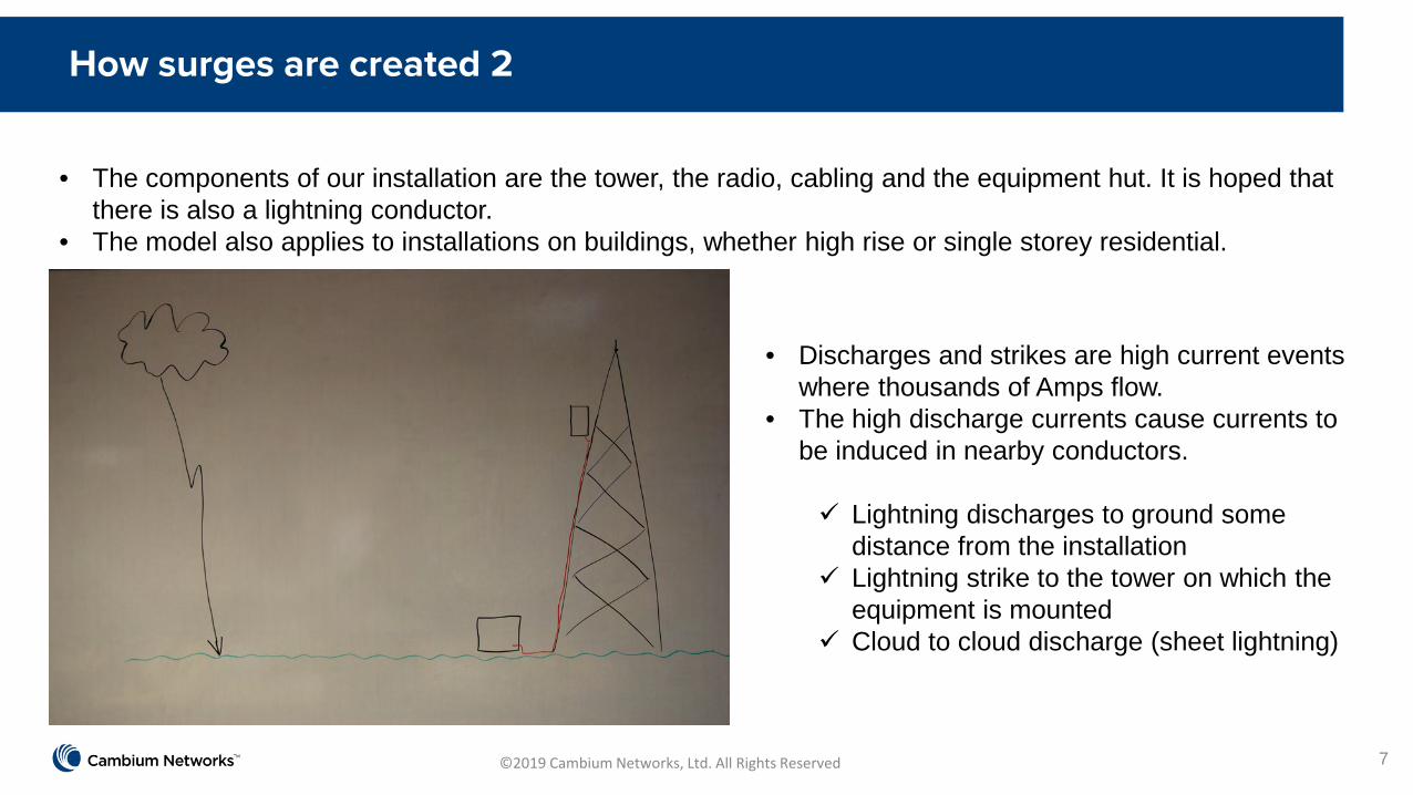
• The components of our installation are the tower, the radio, cabling and the equipment hut. It is hoped that there is also a lightning conductor.
• The model also applies to installations on buildings, whether high rise or single storey residential.
How surges are created 2
7
• Discharges and strikes are high current events where thousands of Amps flow.
• The high discharge currents cause currents to be induced in nearby conductors.
Lightning discharges to ground some distance from the installation
Lightning strike to the tower on which the equipment is mounted
Cloud to cloud discharge (sheet lightning)
©2019 Cambium Networks, Ltd. All Rights Reserved
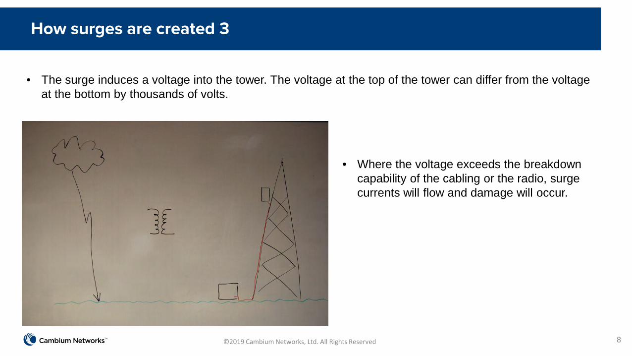
• The surge induces a voltage into the tower. The voltage at the top of the tower can differ from the voltage at the bottom by thousands of volts.
How surges are created 3
8
• Where the voltage exceeds the breakdown capability of the cabling or the radio, surge currents will flow and damage will occur.

©2019 Cambium Networks, Ltd. All Rights Reserved
Why is the equipment susceptible
9
• The casing of the radio is attached to ground.• The incoming Ethernet cable is isolated from
the radio ground but has a breakdown voltage of 2kV typical.
• Surges lower than 2kV cannot exceed the isolation voltage so no breakdown current flows, no damage occurs.
• A surge exceeding 2kV will exceed the breakdown voltage of the transformer.
• Once breakdown occurs large destructive currents can flow.
• It’s a problem at the top and at the bottom of the mast.

©2019 Cambium Networks, Ltd. All Rights Reserved
Applicable standards 1
10
• To facilitate the design of robust systems, standardised tests for use by designers and test houses have been developed to emulate surge levels seen in deployments.
• Equipment is tested with different levels of test surge depending on the expected location of the installation.
• IEC 61000-4-5 Level 4 is applicable to tower mount equipment.
• Testing is performed with the surge generator injecting the surge, 4kV, 10/700us, 200A, directly into the equipment under test.
• The test setup shown requires the use of a surge protector (Lightning Protection Unit – LPU) as part of the system under test.

©2019 Cambium Networks, Ltd. All Rights Reserved
Applicable standards 2
11
• Equipment under test at Cambium• 2kV capability without external surge suppression.

©2019 Cambium Networks, Ltd. All Rights Reserved
How surge protection devices work 1
12
• The drop cable is connected to the surge protector before carrying on to the radio.
• The surge protection device limits the voltage on any pin to less than 200V.
• Zeners are able to absorb 100s of Amps during the brief surge period.

©2019 Cambium Networks, Ltd. All Rights Reserved
How surge protection devices work 2
13
• The radio has been shown to survive 2kV surges in the lab.

©2019 Cambium Networks, Ltd. All Rights Reserved
How surge protection devices work 3
14
• Mounted on the tower, the radio can survive 2kV surges.
• The Ethernet transformer provides the isolation.
• What if the surge exceeds 2kV?
©2019 Cambium Networks, Ltd. All Rights Reserved
How surge protection devices work 4
15
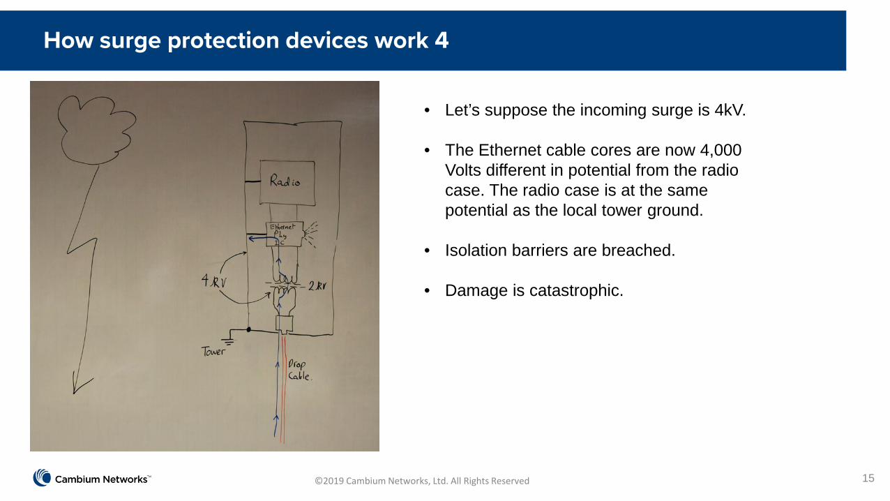
• Let’s suppose the incoming surge is 4kV.
• The Ethernet cable cores are now 4,000 Volts different in potential from the radio case. The radio case is at the same potential as the local tower ground.
• Isolation barriers are breached.
• Damage is catastrophic.

©2019 Cambium Networks, Ltd. All Rights Reserved
How surge protection devices work 5
16
• The surge protector limits the voltage of the surge to 200V.
• The energy and current in the surge are shunted to ground by the diodes (100A, kW).
• The radio sees a small surge of 200V, well within its 2kV capability.

©2019 Cambium Networks, Ltd. All Rights Reserved
How surge protection devices work 6
17
• Most surge protection devices use either Gas Discharge Tubes (GDT) or semiconductor diodes, or a combination of the two.
• GDT solutions tend to be cheaper for a given power handling capability.• However, GDT devices have a lifetime limited to a maximum number of surges.• Silicon-based solutions do not suffer wear out due to surge absorption.
©2019 Cambium Networks, Ltd. All Rights Reserved
Cable shielding 1
18
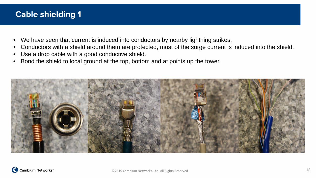
• We have seen that current is induced into conductors by nearby lightning strikes.• Conductors with a shield around them are protected, most of the surge current is induced into the shield.• Use a drop cable with a good conductive shield. • Bond the shield to local ground at the top, bottom and at points up the tower.

©2019 Cambium Networks, Ltd. All Rights Reserved
Cable shielding 2
19
• Without a shield the surge is induced directly onto the Ethernet wires, the surge protection devices have to handle a large surge.

©2019 Cambium Networks, Ltd. All Rights Reserved
Cable shielding 3
20
• With a shield most of the surge is induced into that shield.
• The current is able to flow to the local ground.
• A smaller amount of surge appears on the Ethernet cores and is handled by the protection devices in the surge protector.
©2019 Cambium Networks, Ltd. All Rights Reserved
Cable shielding 4
21
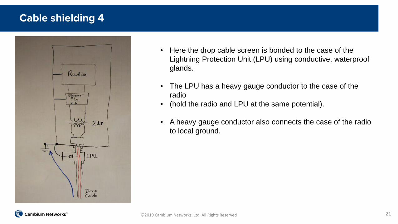
• Here the drop cable screen is bonded to the case of the Lightning Protection Unit (LPU) using conductive, waterproof glands.
• The LPU has a heavy gauge conductor to the case of the radio
• (hold the radio and LPU at the same potential).
• A heavy gauge conductor also connects the case of the radio to local ground.
©2019 Cambium Networks, Ltd. All Rights Reserved
Best installation practice 1
22
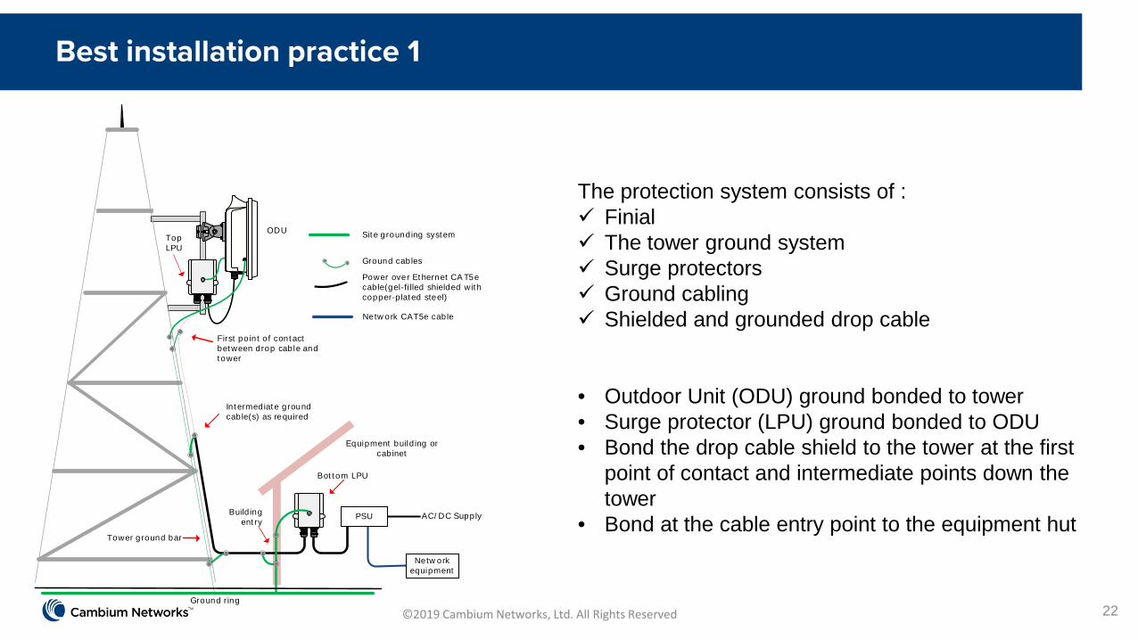
The protection system consists of : Finial The tower ground system Surge protectors Ground cabling Shielded and grounded drop cable
• Outdoor Unit (ODU) ground bonded to tower• Surge protector (LPU) ground bonded to ODU• Bond the drop cable shield to the tower at the first
point of contact and intermediate points down the tower
• Bond at the cable entry point to the equipment hutBuild ing
ent ry
Ground ring
First po in t o f contact between drop cable and t ower
ODU
Bot t om LPU
Top LPU
Intermediate ground cable(s) as required
AC/ DC Supply
Equipment build ing or cabinet
Tower ground bar
Ground cables
Power over Ethernet CA T5e cable(gel-fi lled shielded wit h copper-p lat ed steel)
Sit e grounding system
Netw ork CAT5e cable
PSU
Netw ork equipment

©2019 Cambium Networks, Ltd. All Rights Reserved
Best installation practice 2
23
• Grounding system is connected to the tower at frequent intervals.
• The installation is not reliant on metal contact on brackets.
• Self amalgamating tape is used to seal the drop cable where a grounding strap is attached.
ODU
ODU m ounted on pole w it h bracket
Top LPU mounted on po le wit h U-bolt from LPU kit
Drop cable grounding po int
ODU to t op LPU ground cable
Mount ing po le
ODU to grounding system
ODU to t op LPU drop cable
Drop cable t o bot tom LPU
Grounding system
Grounding point s at opposi te sides of ODU
©2019 Cambium Networks, Ltd. All Rights Reserved
Best installation practice 3
24
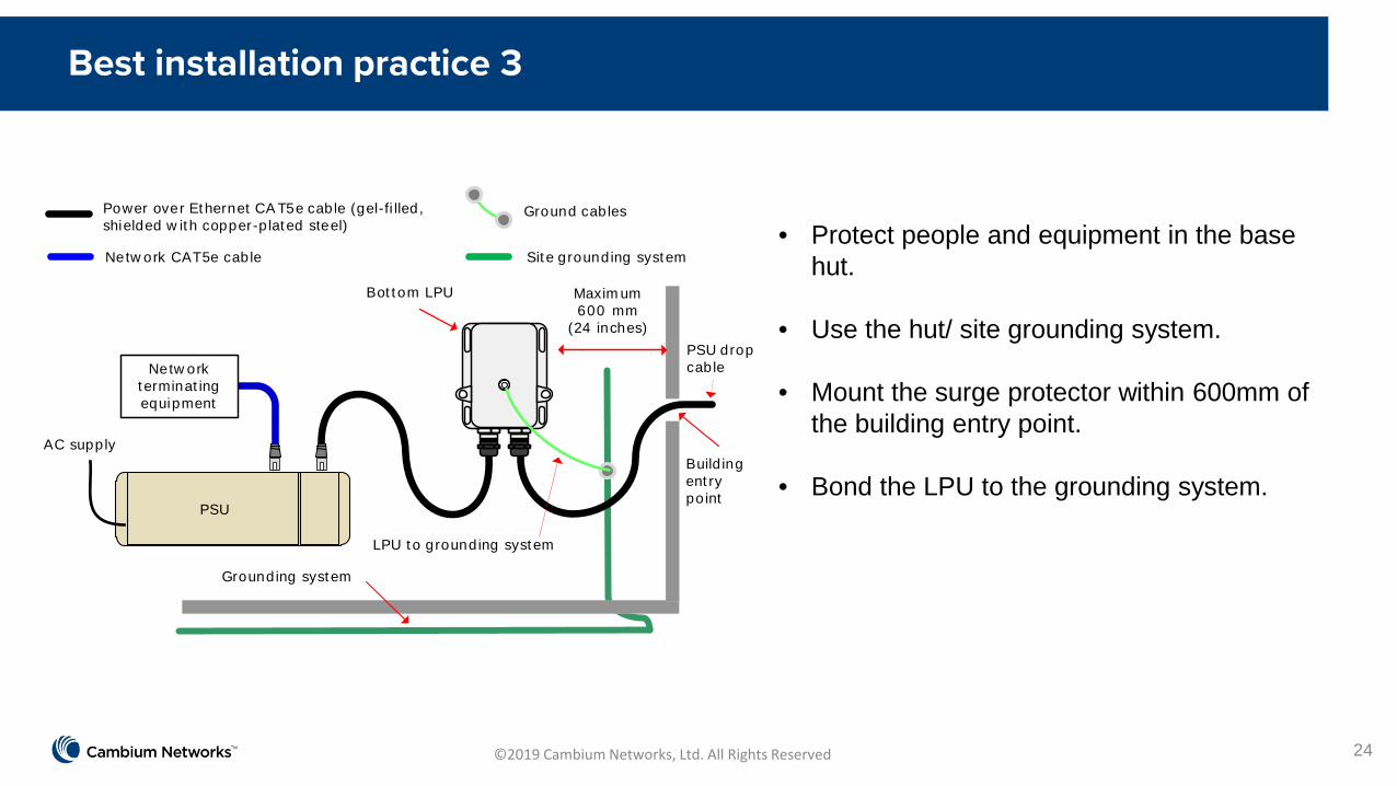
• Protect people and equipment in the base hut.
• Use the hut/ site grounding system.
• Mount the surge protector within 600mm of the building entry point.
• Bond the LPU to the grounding system.
Maxim um600 mm
(24 inches)
Bot t om LPU
Grounding system
Build ing ent ry po int
LPU to grounding system
PSU drop cable
AC supply
Netw ork t erminat ingequipment
Ground cablesPower over Ethernet CA T5e cable (gel-fi lled, shielded w it h copper-p lat ed steel)
Netw ork CAT5e cable Sit e grounding system
PSU

©2019 Cambium Networks, Ltd. All Rights Reserved
Conclusions
25
• Cambium equipment has been designed and proven to survive surge levels experienced on towers.
• A well-designed and implemented installation with good grounding, cabling and surge protection is an essential component in a robust, trouble free communications system.
• Cannot protect against all surge events, but can significantly improve the robustness of the installation.

©2019 Cambium Networks, Ltd. All Rights Reserved
Questions
26
That’s all clear then?

©2019 Cambium Networks, Ltd. All Rights Reserved
Feedback
27
Did you get what you were expecting?
