lightweight 155mm (lw155) system performance specification
TRANSCRIPT
1
LIGHTWEIGHT 155mm (LW155)
SYSTEM PERFORMANCE SPECIFICATION
1.0 SCOPE
1.1 Identification (TBD)
1.2 System Overview The LW 155 will replace all US Marine Corps(USMC) cannon systems and be used as a direct support weapon.The US Army (Army) will use the system as a general supportweapon in the light forces and as a direct support weapon for theLight Cavalry Regiment replacing all of the M198 155mm towedhowitzers.
1.3 Document Overview This system specification describes theconfiguration of the Lightweight 155 (LW 155) formerly known asthe Advanced Towed Cannon System (ATCAS). This specification isused to describe the performance requirements of the LW 155 andcontains the operational and interface criteria for the system.Both services require the system to have the capability to acceptthe Pre-planned Product Improvements (P3I) listed in appendix Aof this specification. The Army requires that a number of theP3I be on their production system; while, the USMC may procurethem, as a separate action, to be added to their productionsystem.
1.4 Security Classification (TBD)
2.0 APPLICABLE DOCUMENTS The following documents form a part ofthis specification to the extent specified herein. In the eventof conflict between the documents referenced herein and thecontent of this specification, the content of this specificationshall be considered a superseding requirement.
2.1 Government
2.1.1 Specifications and Standards
2.1.1.1 Mandatory
2
QPL-46168-27 Coating, Aliphatic Polyurethane, ChemicalAgent Resistant
MIL-STD-209(H) Slinging and Tiedown Provisions for Liftingand Tying Down
MIL-STD-810E Environmental Test Methods and EngineeringGuidelines
2.1.1.2 Guidance
ATPD 2131 FMTV Performance Specification
APTD 2185 MTVR Performa nce Specification
MIL-STD-171(E) Finishing of Metal and Wood Surfaces
MIL-STD-130(H) US Military Property, Identification Marking
MIL-STD-1366(C) Transportability Criteria
MIL-STD-1472(D) Human Engineering Design Criteria for MilitarySystems
MIL-STD-1791(2) Designing for Internal Aerial Delivery inFixed Wing Aircraft
QPL-P-C-437 Cleaning Compounds. High Pressure Steam Cleaners
2.1.2 Drawings
Interface Drawings for 155mm Ammunition, Quadrilateral MOU#9357971
2.1.3 Other
MIL-HDBK-784 Guidelines/Designs to Minimize Contaminationand to Facilitate Decontamination of MilitaryVehicles and Other Equipment
RAM Rationale Report (RRR), 2 June 95, Us Army TRADOC AdvancedTowed Cannon System (ATCAS) Reliability andMaintainability Requirements
3
ANSI C95.1-91
2.2 Non-Government
2.2.1 Specifications and Standards None.
2.2.2 Drawings
American Association of Railroads (AAR) Clearance DiagramGabarit Internationale de Chargement (GIC) Clearance Diagram
3.0 SYSTEM REQUIREMENTS
3.1 System Description The LW 155 will provide close and deepfire support and interdiction fires. It will be lightweightwithout sacrificing range, stability, accuracy or durability.The system is designed as a howitzer, prime mover and associatedequipment. The system shall be deployable to any region andshall operate in most climatic conditions. The US Marine Corpswill use the weapon as a direct support weapon, replacing allexisting cannon systems. The US Army will use the LW 155 as ageneral support weapon in the light forces and as a directsupport weapon for the Light Cavalry Regiment, replacing the M198155mm towed howitzer.
3.2 Characteristics
3.2.1 Functional Characteristics
3.2.1.1 Mission The LW 155 shall shoot, move and communicate inaccordance with the combat intensity levels and mission profilesspecified in the LW 155 Design Reference Mission Profile (section2 of the ATCAS RRR).
3.2.1.2 Threat Army light forces’ artillery and USMC artillerycan expect to face threat forces from light, guerrilla forces tomassed mechanized formations in combat across the operationalcontinuum from operations other than war (OOTW) to war. Threatcannon systems will range from antiquated to modern long rangeself-propelled and towed systems. Many cannon systems will rivalor exceed western systems in range, rate of fire and precision.Threat artillery (cannon, rocket and missile) and aircraft willbe able to deliver a full range of ordnance, including
4
conventional, Improved Conventional Munitions (ICM), Dual PurposeImproved Conventional Munitions (DPICM), smoke, fuel airexplosives (FAE), electronic countermeasures (ECM), scatterablemines, guided, and homing submunitions. A small number ofcountries will be able to employ nuclear, chemical and biologicalweapons. Maneuver, reconnaissance and unconventional forces willpose the ground force threat. Threat maneuver and artilleryforces will use equipment from a wide range of countries.Furthermore, armies will become more sophisticated as a result oftechnology proliferation and synchronization of maneuver and firesupport systems. Electronic warfare capabilities will vary byadversary. However, threats to battalion and batterycommunications systems may be effective in disrupting firecontrol and artillery command and control. Reconnaissance andtarget acquisition capabilities will also vary among threatforces. These will range from single round locating radar,modernized sound ranging systems, and unmanned aerial vehicles(UAVs) to reliance on visual acquisition means. Threats to theLW 155 throughout its life cycle will increase as a result oftechnology improvements in target acquisition, munitions anddelivery systems. Improvements in threat force mobility andarmor will directly affect the survivability of light weaponsystems. Current towed systems’ limited mobility and greaterreaction times make them more susceptible to enemy counterfire.
3.2.2 Performance Characteristics
3.2.2.1 Range
3.2.2.1.1 Maximum Range The LW 155 indirect fire maximum rangeshall be at least 30 (threshold) to 40 (objective) kilometerswith rocket-assisted US munitions (i.e., M549A1) and 22.5(threshold) to 30 (objective) kilometers with unassisted USmunitions (i.e., M795, M825A1 or XM898) with the M203A1propelling charge.
3.2.2.1.2 Minimum Range The LW 155 high angle indirect fireminimum range firing the M107 projectile and current propellingcharges shall not be greater than 3,700 (threshold) to 2,700(objective) meters.
3.2.2.1.3 Range Overlap The LW 155 shall be capable of engagingtargets between minimum and maximum range without any gaps.
5
3.2.2.2 Bias & Precision
3.2.2.2.1 Bias Bias errors cause the offset between the fall-of-shot mean point of impact (MPI) and the target. The goal ofartillery is to center the MPI on the target. The LW 155 shallhave a bias circular error probable (CEP) not exceeding 200meters (threshold) to 50 meters (objective) at 25 kilometers.This is based upon a two hour MET with 20 kilometer spatialseparation from the MET station to the midpoint of thetrajectory, firing the M864 projectile at low angle with themaximum charge, and a target location accuracy of 10 meters.
3.2.2.2.2 Precision Precision errors cause the fall-of-shotpattern. They are related to the interaction of componenttolerances, such as cannon, fire control, projectile, andpropellant. The LW 155 range precision probable error for lowangle indirect fire shall not be greater than 0.0030 (.3 percent)of range for unassisted projectiles and 0.0035 (.35 percent) ofrange for assisted projectiles. Deflection probable error shallnot exceed one mil at any range in low angle fire and two mils inhigh angle fire for both assisted and unassisted projectiles.
3.2.2.3 Rate of Fire
3.2.2.3.1 Maximum Rate of Fire The maximum rate of fire for theLW 155 shall be at least five (threshold) to eight (objective)rounds per minute firing all allowable shell/charge combinations(Copperhead excluded) for not less than two minutes in low anglefire (800 mils or less).
3.2.2.3.2 Sustained Rate of Fire The sustained rate of fireshall be at least two rounds per minute firing all allowableshell/charge combinations (Copperhead excluded) in low angle fire(800 mils or less) for as long as ammunition is available. As aminimum, this quantity should equal the gun section’s basiccombat load.
3.2.2.4 Responsiveness
3.2.2.4.1 Emplacement The LW 155 (a single weapon) shall beemplaced and ready to fire (weapon is laid, at least onereference point has been established, one round of ammunition is
6
ready to be loaded, and communications with the Fire DirectionCenter (FDC) are established) by no more than five crewmenincluding the gunner and four other cannoneers in three(threshold) to two (objective) minutes or less, after the primemover has stopped in position.
3.2.2.4.2 Displacement Once emplaced, the LW155 (howitzer,crew, prime mover, and associated equipment) shall be loaded andprepared to immediately depart the current location, by no morethan five crewmen in two (threshold) to one (objective) minute.
3.2.2.4.3 Out-of-Traverse Mission During conduct of a firemission, the LW155 shall be shiftable up to 3200 mils left orright of center of traverse and laid/ready to fire on a newtarget, by no more than five crewmen including the gunner andfour other cannoneers, in three minutes (threshold) to twominutes (objective) from receipt of the new mission.
3.2.2.4.4 Low Angle Fire The LW155, when emplaced in a firingposition and with a fuzed projectile ready to load, shall respondto an in-traverse (within 400 mils left or right of centertraverse) low angle fire mission, with first round fired within30 (threshold) to 20 (objective) seconds from receipt of firecommands (excluding Copperhead missions).
3.2.2.4.5 High Angle Fire The LW155, when emplaced in a firingposition and with a fuzed projectile ready to load, shall respondto an in-traverse, high angle mission (1000-1275 mils) with firstround fired within 45 (threshold) to 30 (objective) seconds fromreceipt of the fire commands (excluding Copperhead missions).
3.2.2.5 Direct Fire The LW155 shall be capable of direct fireat a quadrant elevation of zero mils on level ground, with atleast charge seven white bag (M4A2), and shall have a sight thatprovides a direct fire capability.
3.2.2.6 Survivability
3.2.2.6.1 Nuclear, Biological and Chemical (NBC) ProtectionThe LW155 shall be capable of withstanding the materiel damagingeffects of NBC contamination, decontaminates, and the standarddecontamination procedures. MIL-HDBK-784 is offered as a guide.Chemical agent resistant coating (CARC) paint shall be used per
7
QPL-46168-27. Critical LW155 components shall be decontaminableby the crew using standard organic decontamination equipment in10 (threshold) to 5 (objective) minutes. (Critical componentsare those components required to be manually handled duringconduct of emplacement and fire mission.) The LW155 shall bedesigned to facilitate decontamination of the howitzer, withoutdismantling or removing integral components of the end item. TheLW155 design shall minimize areas where contaminating anddecontaminating agents can collect.
3.2.2.6.2 Ballistic Vulnerability The LW155 System missioncritical components (e.g., fire control instruments, hydraulicsystems, and cables) shall be designed and configured to minimizetheir vulnerability to ballistic fragments.
3.2.2.6.3 Soldier Survivability The LW155 design shall maximizesoldier survivability both as it affects the crew and the forceas a whole. This includes minimizing the system’s visual,auditory, and RF signature and exploiting the system’s mobilityand rapid emplacement and displacement capability.
3.2.2.7 Mobility
3.2.2.7.1 Towing The LW155 shall not exceed the towingcapabilities of the prime mover. Guidance is provided in ATPD2131 (Family of Medium Tactical Vehicles, FMTV) and ATPD 2185(Medium Tactical Vehicle Replacement, MTVR). Prime mover maximumtowing capacity is independent of the payload. As an objective,the track of the LW155 will not be wider than that of the FMTVand MTVR prime movers.
3.2.2.7.2 Fording The LW155 shall have a fording (watercrossing) capability equal to that of the prime mover. Duringunprepared fording operations, at least 30 inches of water (freshor salt), without addition of special equipment or adjustments.During prepared fording operations, up to 60 inches of water(fresh or salt, including waves), with special equipment oradjustments.
3.2.2.7.3 Emergency Repair The LW155 shall be capable ofaccepting a prime mover (M813, FMTV, or MTVR) wheel as a spare oranother technical solution (i.e., run-flat) for emergency repairor replacement.
8
3.2.2.7.4 Speed The LW155 shall provide a suspension system toachieve towing speeds of not less than 88 kph (55 mph) on primaryroads, 56 kph (35 mph) on secondary roads, and 24 kph (15 mph)cross-country.3.2.2.7.5 Blackout Markers The LW155 shall be designed toincorporate blackout markers (with reduced infrared signature)and US Department of Transportation (DOT) rear lights while beingtowed.
3.2.2.7.6 Braking The LW155 on-board brake system, whenattached to the prime mover, shall provide effective andcontrolled braking of the LW155 when stopping or slowing downfrom the maximum towing speeds on all road types, and whendescending slopes of up to 60 percent. Additionally, the LW155brakes shall be designed to preclude locking of the howitzerbrakes except in an emergency (prime mover brake failure). TheLW155 shall have manually operated parking brakes.
3.2.2.8 Transportability The general requirements of MIL-STD-1366, in concjunction with the requirements set forth below, maybe used as a guide for determining dimensions, weightconstraints, lifting and tiedown provisions for worldwidetransportation of systems.
3.2.2.8.1 Fixed Wing The LW155 with its prime mover shall beair transportable on USAF C-141B and larger cargo aircraft. Atleast two LW155s shall be transportable in a single C-130aircraft (without prime movers). MIL-STD-1791 is offered as aguide. The LW155 shall be configured for ease of loading andunloading from the above USAF aircraft without disassembly orassembly. The LW155 shall be air droppable using low-velocityaerial delivery (LVAD) from the C-130 and larger USAF heavy-dropcargo aircraft.
3.2.2.8.2 Rotary Wing The LW155 shall be externallytransportable as a complete mission package (howitzer, crew,ammunition, and section equipment) by the CH-53E and CH-47D inhigh, hot conditions and by the MV-22 and CH-53D in low, coolconditions. The lift provisions for airmobile operations shallbe designed to provide for a stable load at all speeds up to 200knots.
9
3.2.2.8.3 Marine The LW155 shall be transportable by all typecargo ships and landing craft. The physical characteristics anddimensions of the LW155, while attached to the prime mover, shallallow loading and securing aboard naval shipping and landingcraft larger than the Landing Craft Mechanized-8 (LCM-8).
3.2.2.8.4 Highway and Rail For rail and highway transportation,the LW155 shall meet both the AAR and GIC clearance diagrams.The LW155 shall be transportable by military and commercialtransporters. The LW155 (at shipping weight) shall incur nodamage when subjected to the MIL-STD-810 rail impact test. Thehowitzer, when towed by its prime mover, shall meet the highwaylegal limits of US and North Atlantic Treaty Organization (NATO)countries.
3.2.2.8.5 Lifting and Tiedown Provisions The LW155 shall beequipped with military standard lifting and tiedown provisions inaccordance with MIL-STD-209.
3.2.3 External Interfaces
3.2.3.1 Ammunition The LW155 shall interface with all fieldedand developmental US and NATO standard 155mm munitions and allcurrent and developmental propelling charges (excluding liquidpropellant) based on standard projectile/charge compatibility.Guidance is provided in the Interface Drawings for 155mmAmmunition Quadrilateral, MOU #9357971.
3.2.3.2 Prime Mover Interface The LW155 shall interface withthe intended prime movers. The Army’s intended prime mover isthe FMTV. The USMC’s intended prime mover is the MTVR. Thecurrent family of 5-ton trucks (ie, M813) may also serve as atemporary prime mover pending full fielding of the newervehicles. In addition the system shall be moveable by MaterialHandling Equipment organic to USMC Artillery, the USMC LightArmored Vehicle (LAV), Advanced Amphibious Assault Vehicle ( AAAV)and Landing Vehicle Track, Personnel (LVTP-7).
3.2.3.3 Command, Control and Communications Interface The LW155shall interface with the Battery Computer System (BCS),Lightweight Computer Unit (LCU), communications equipment, anddevelopmental systems. The LW155 shall be designed to
10
accommodate appropriate hardware to attach the M93/M94 MuzzleVelocity System (MVS), a Gun Display Unit (GDU) of the BCS, anddevelopmental fire direction computers and displays.
3.2.3.4 Intrasystem Interfaces The LW155 shall accommodate/provide intrasystem interfaces, including the vehicle, the crew,the weapon, Basic Issue Items (BII), Additional Authorized List(AAL) items, Material Handling Equipment (MHE), diagnosticequipment, and optical fire control.
3.2.3.5 Preplanned Product Improvements (P 3I) The LW155 shallallow for future flexibility and expansion. The Army LW155requires a number of enhancements beyond the base howitzer(Appendix A). The USMC may procure these items as P 3I.
3.2.4 Physical Characteristics
3.2.4.1 Weight The LW155 threshold weight is 9,000 pounds. Theobjective weight is as light as practical without sacrificingother performance characteristics included in this document, suchas range, accuracy, survivability, and reliability/durability.The system weight includes the basic weapon, optical fire controland section equipment needed to fire the weapon. Non-criticalsection equipment, M93/94, and radios are not included.
3.2.4.2 Surface Finish The requirements of MIL-STD-171 may beused as a guide for the ontroll and preventionn of corrosion forthe LW155. A final protective finish shall be chemical anddecontamination resistant. The LW155 shall be capable ofwithstanding the materiel damaging effects of NBC contamination,decontaminates, and procedures used to decontaminate. The LW155shall have corrosion resistant fearutes to minimize damage toexposed and non-exposed metal-bearing surfaces caused byprolonged exposure to salt water spray (96-hour salt spray)during amphibious operations..
3.2.5 Quality Factors
3.2.5.1 Reliability The LW155 Mean Rounds Between System Abort(MRBSA) shall be no less than 800 rounds (threshold) to 900rounds (objective), to be demonstrated with an 80% confidence,when employed IAW with the LW155 Design Reference MissionProfile. An SA is defined, in accordance with the LW155 Failure
11
Definition and Scoring Criteria (section 3 of the ATCAS RRR), asany failure resulting in the loss or degradation of a MissionEssential Function (MEF) to a level below the minimum acceptablelevel defined as follows:
MEF SA CriteriaTo Shoot :Maximum Rate of Fire (2 minutes) Less than 2 rounds per minuteSustained Rate of Fire (indefinite) Less than 1 round per minuteMaximum Range (with rocket assist) Less than 15 kmMaximum Range (unassisted) Less than 9 km
To Move :Primary Speed Less than 30 km per hourSecondary Speed Less than 15 km per hourCross-Country Speed Less than 5 km per hour
3.2.5.2 Maintainability
3.2.5.2.1 Operator/Crew Preventive Maintenance Checks andServices (PMCS) The system Operator/Crew PMCS shall not exceed1.0 (threshold) to 0.5 (objective) maintenance clock-hours perday. Operator/Crew PMCS shall include all systematic care,inspection and servicing performed by the Operator/Crew asprescribed in the technical manual.
3.2.5.2.2 Corrosion Prevention Control PMCS PMCS required tokeep the system corrosion free shall not exceed 2.0 (threshold)to 1.0 (objective) maintenance clock-hours per week.
3.2.5.2.3 Maintenance Ratio (MR ) The system MR shall not exceed.04 (threshold) to .02 (objective) maintenance man-hours peroperating hour. The MR shall include all maintenance demands,both scheduled and unscheduled (non-essential and essential),performed at the Unit, Direct Support and General Support levels.The MR shall exclude all maintenance, scheduled and unscheduled,performed at the Operator/Crew level. Specifically, it shallexclude all Operator/Crew PMCS and all Operator/Crew correctablemaintenance procedures prescribed in the technical manual. AnEssential Unscheduled Maintenance Demand is defined as anymaintenance action resulting from an Essential Function Failure(EFF). An EFF is defined, in accordance the LW155 FailureDefinition and Scoring Criteria, as the loss or degradation of an
12
MEF to a level below the minimum acceptable level defined asfollows:
MEF EFF Criteria
To Shoot :Maximum Rate of Fire (2 minutes) Less than 5 rounds per minuteSustained Rate of Fire (indefinite) Less than 2 round per minuteMaximum Range (with rocket assist) Less than 27 kmMaximum Range (unassisted) Less than 18 kmMinimum Range (high angle) Less than 3.7 kmDirect Fire Loss of direct fire ability
To Move :Primary Speed Less than 30 km per hourSecondary Speed Less than 15 km per hourCross-Country Speed Less than 5 km per hour
Fording Less than Prime Mover ability
3.2.5.2.4 Unit Mean Time To Repair (MTTR) The MTTR shall notexceed 30 minutes (threshold) to 15 minutes (objective) for allmaintenance tasks, both scheduled and unscheduled, performed atthe Unit level.
3.2.5.2.5 Direct Support MTTR The MTTR shall not exceed 2 hours(threshold) to 1 hour (objective) for all maintenance tasks, bothscheduled and unscheduled, performed at the Direct Support level.
3.2.5.2.6 Maintenance Tasks No less that 70% of all maintenancetasks shall be performed at the Operator/Crew and/or Unit levels.No more than 25% of all maintenance tasks shall be performed atthe Direct Support/General Support levels. No more than 5% ofall maintenance tasks shall be performed at the Depot level.
3.2.5.2.7 Accessibility The system shall provide a means forroutinely inspecting, testing and cleaning subsystems withoutremoval of major assemblies. Accessibility shall also beprovided at Line Replaceable Unit (LRU) and Shop Replaceable Unit(SRU) levels for ease of functional and diagnostic testing andrepair by the Direct Support, General Support and Depotmaintenance.
13
3.2.5.3 Durability
3.2.5.3.1 Cannon Tube Fatigue Life The cannon tube shall have afatigue life of at least 2,650 equivalent full charge (EFC)rounds, based on firing M549A1 or M864 projectiles with M203A1propelling charge. The cannon fatigue life shall exceed the wearlife.
3.2.5.3.2 Breech Mechanism Fatigue Life The breech mechanismshall have a fatigue life of at lease 5,300 (threshold) to 10,000(objective) EFC rounds based on the M203A1 charge.
3.2.5.3.3 Recoil Mechanism Service Life The recoil mechanismshall have a service life of 5,300 (threshold) to 10,000(objective) EFC rounds based on the M203A1 charge.
3.2.5.3.4 Carriage and Cradle Service Life The carriage andcradle shall not require replacement for the life of the system.
3.2.6 Environments
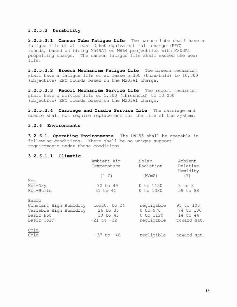
3.2.6.1 Operating Environments The LW155 shall be operable infollowing conditions. There shall be no unique supportrequirements under these conditions.
3.2.6.1.1 Climatic Ambient Air Solar Ambient Temperature Radiation Relative
Humidity ( o C) (W/m2) (%)
HotHot-Dry 32 to 49 0 to 1120 3 to 8Hot-Humid 31 to 41 0 to 1080 59 to 88
BasicConstant High Humidity const. to 24 negligible 95 to 100Variable High Humidity 26 to 35 0 to 970 74 to 100Basic Hot 30 to 43 0 to 1120 14 to 44Basic Cold -21 to -32 negligible toward sat.
ColdCold -37 to -46 negligible toward sat.
14
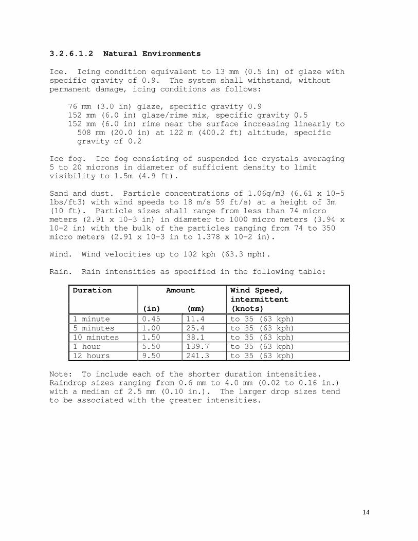
3.2.6.1.2 Natural Environments
Ice. Icing condition equivalent to 13 mm (0.5 in) of glaze withspecific gravity of 0.9. The system shall withstand, withoutpermanent damage, icing conditions as follows:
76 mm (3.0 in) glaze, specific gravity 0.9 152 mm (6.0 in) glaze/rime mix, specific gravity 0.5 152 mm (6.0 in) rime near the surface increasing linearly to 508 mm (20.0 in) at 122 m (400.2 ft) altitude, specific gravity of 0.2
Ice fog. Ice fog consisting of suspended ice crystals averaging5 to 20 microns in diameter of sufficient density to limitvisibility to 1.5m (4.9 ft).
Sand and dust. Particle concentrations of 1.06g/m3 (6.61 x 10⁻⁵lbs/ft3) with wind speeds to 18 m/s 59 ft/s) at a height of 3m(10 ft). Particle sizes shall range from less than 74 micrometers (2.91 x 10⁻³ in) in diameter to 1000 micro meters (3.94 x10⁻² in) with the bulk of the particles ranging from 74 to 350micro meters (2.91 x 10⁻³ in to 1.378 x 10⁻² in).
Wind. Wind velocities up to 102 kph (63.3 mph).
Rain. Rain intensities as specified in the following table:
Duration Amount Wind Speed,intermittent
(in) (mm) (knots)1 minute 0.45 11.4 to 35 (63 kph)5 minutes 1.00 25.4 to 35 (63 kph)10 minutes 1.50 38.1 to 35 (63 kph)1 hour 5.50 139.7 to 35 (63 kph)12 hours 9.50 241.3 to 35 (63 kph)
Note: To include each of the shorter duration intensities.Raindrop sizes ranging from 0.6 mm to 4.0 mm (0.02 to 0.16 in.)with a median of 2.5 mm (0.10 in.). The larger drop sizes tendto be associated with the greater intensities.
15
Salt fog. Salt fog exposure for periods up to 96 hours. Fortest purposes, the salt fog solution shall be 5% by weight ofsodium chloride in 95% by weight distilled water. Thetemperature in the exposure zone shall be maintained between 32 o
and 35 oC (87.6 o and 95.0 oF). Fog density shall be approximately31 (0.79 gal) of salt solution per 0.3 m3 (10.6 ft3) of chambervolume per 24 hours .
Hail. Hailstones up to 51 mm (2 in.) in diameter.
3.2.6.1.3 Induced Environments
Road shock. The LW155 shall not be damaged from road shock whentowed IAW the system DRMP and within the prime mover mobility andtowing specifications.
Vibration. The LW155 shall not be damaged from vibration whenoperated IAW the system DRMP and within the prime mover mobilityand towing specifications.
Gun firing shock. The LW155 shall not be damaged from the firingshock of any authorized projectile/propelling charge combination.
Low-Velocity Aerial Delivery (LVAD). The LW155 will remain fullyoperational after LVAD.
3.2.6.2 Non-operating Environments The LW155 shall not incurpermanent damage from exposure to the non-operating environmentsspecified below. Following exposure, the LW155 shall be capableof performing as specified by 3.2.2 and its sub-paragraphs.During exposure, the LW155 shall be in a storage or transportconfiguration. For transport and storage not exceeding 90 daysduration, the LW155 shall withstand the environments with nopreservation preparation, special handling, or tranportequipment. The LW155 shall withstand long-term protected storage(inside warehouses or ships) for up to one (threshold) to two(objective) years and remain Fully Mission Capable.
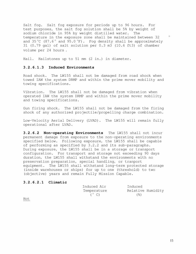
3.2.6.2.1 Climatic Induced Air Induced
Temperature Relative Humidity ( o C) (%)
Hot
16
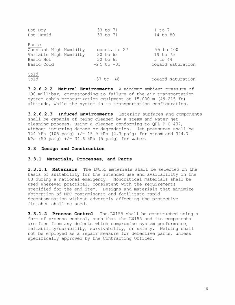
Hot-Dry 33 to 71 1 to 7Hot-Humid 33 to 71 14 to 80
BasicConstant High Humidity const. to 27 95 to 100Variable High Humidity 30 to 63 19 to 75Basic Hot 30 to 63 5 to 44Basic Cold -2 5 to -33 toward saturation
ColdCold -37 to -46 toward saturation
3.2.6.2.2 Natural Environments A minimum ambient pressure of100 millibar, corresponding to failure of the air transportationsystem cabin pressurization equipment at 15,000 m (49,215 ft)altitude, while the system is in transportation configuration.
3.2.6.2.3 Induced Environments Exterior surfaces and componentsshall be capable of being cleaned by a steam and water jetcleaning process, using a cleaner conforming to QPL P-C-437,without incurring damage or degradation. Jet pressures shall be724 kPa (105 psig) +/- 15.9 kPa (2.3 psig) for steam and 344.7kPa (50 psig) +/- 34.6 kPa (5 psig) for water.
3.3 Design and Construction
3.3.1 Materials, Processes, and Parts
3.3.1.1 Materials The LW155 materials shall be selected on thebasis of suitability for the intended use and availability in theUS during a national emergency. Noncritical materials shall beused wherever practical, consistent with the requirementsspecified for the end item. Designs and materials that minimizeabsorption of NBC contaminants and facilitate rapiddecontamination without adversely affecting the protectivefinishes shall be used.
3.3.1.2 Process Control The LW155 shall be constructed using aform of process control, such that the LW155 and its componentsare free from any defects which compromise system performance,reliability/durability, survivability, or safety. Welding shallnot be employed as a repair measure for defective parts, unlessspecifically approved by the Contracting Officer.
17
3.3.1.3 Standard, Commercial, and Qualified Parts Parts whichare in current production and available, as indicated byqualified parts lists, shall be used whenever possible. Thenumber of unique parts shall be minimized.
3.3.1.4 Environmental Compliance Design and construction of thesystem shall be in compliance with applicable federal, state andlocal environmental laws and regulations. The use of hazardousand environmentally unacceptable materials shall be eliminated orreduced to an acceptable compliance level.
3.3.1.5 Metric System The LW155 shall be designed in accordancewith the hard metric approach to the maximum extent practicable.
3.3.1.6 Radioactive Material Radioactive material shall not beused unless the performance requirements can not be achievedwithout such use. Any radioactive materials proposed willrequire prior Government authorization for use.
3.3.2 Name Plates and Product Markings The LW155 system and itsassociated parts, subassemblies, and assemblies shall be markedusing MIL-STD-130H as a guide. Serial numbers shall be assignedby the Government.
3.3.3 Interchangeability Like units assemblies, sub-assemblies,and replacement parts shall be physically and functionallyinterchangeable without modification of the items or equipment,individual items shall not be hand-picked for fit or performance.Standard components, parts, tools, fasteners and test equipmentshall be used to the maximum extent practicable.
3.3.4 Safety
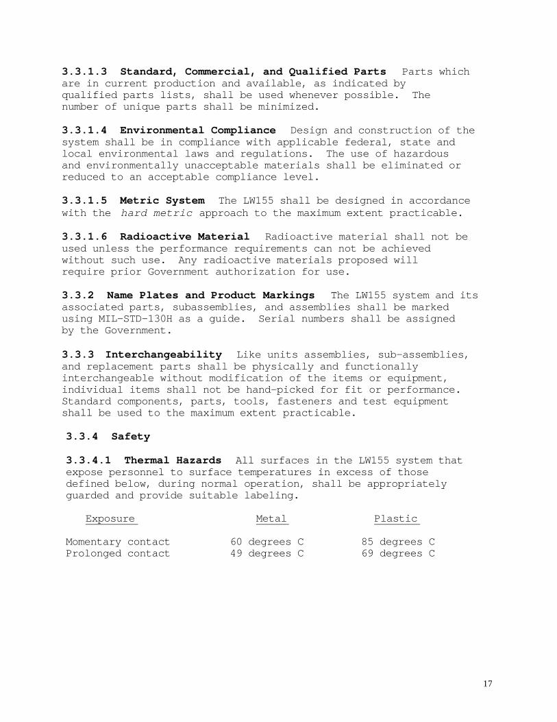
3.3.4.1 Thermal Hazards All surfaces in the LW155 system thatexpose personnel to surface temperatures in excess of thosedefined below, during normal operation, shall be appropriatelyguarded and provide suitable labeling.
Exposure Metal Plastic
Momentary contact 60 degrees C 85 degrees CProlonged contact 49 degrees C 69 degrees C
18
3.3.4.2 Noxious Substances No material, which during any phaseof the system life cycle shall expose personnel to noxioussubstances in excess of the Time Weighted Averages and Short TermExposure Limits specified in the latest publication of theThreshold Limit Values by the American Conference of GovernmentalIndustrial Hygienists.
3.3.4.3 Flammability The use of flammable materials shall beminimized. Components containing flammable materials, fluidsshall minimize the possibility of leaks and spills. Thecombination of assembled components and materials or substancesshall not be a source of unintended ignition and shall notsupport unintended combustion.
3.3.4.4 Mechanical Safety
3.3.4.4.1 Edge Rounding All exposed edges and corners thatpresent a personnel safety hazard shall be suitably protected orrounded to a minimum radius of 13 mm.
3.3.4.4.2 Entrapment Safeguards shall be installed to preventinadvertent contact with, or entrapment of, body parts orclothing in moving parts.
3.3.4.4.3 Mechanical Interconnection The system shall providepositive means to prevent the inadvertent mismatching offittings, couplings, mechanical linkages and electricalconnections, and the system shall minimize the likelihood ofleaks and spills. Coding and markings should not be used as asubstitute for this requirement.
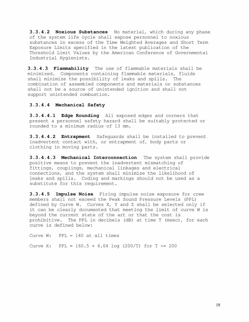
3.3.4.5 Impulse Noise Firing impulse noise exposure for crewmembers shall not exceed the Peak Sound Pressure Levels (PPL)defined by Curve W. Curves X, Y and Z shall be selected only ifit can be clearly documented that meeting the limit of curve W isbeyond the current state of the art or that the cost isprohibitive. The PPL in decibels (dB) at time T (msec), for eachcurve is defined below:
Curve W: PPL = 140 at all times
Curve X: PPL = 160.5 + 6.64 log (200/T) for T <= 200
19
Curve Y: PPL = 6.5 dB above curve X at all times
Curve Z : PPL = 13 dB above curve X at all times
3.3.4.6 General
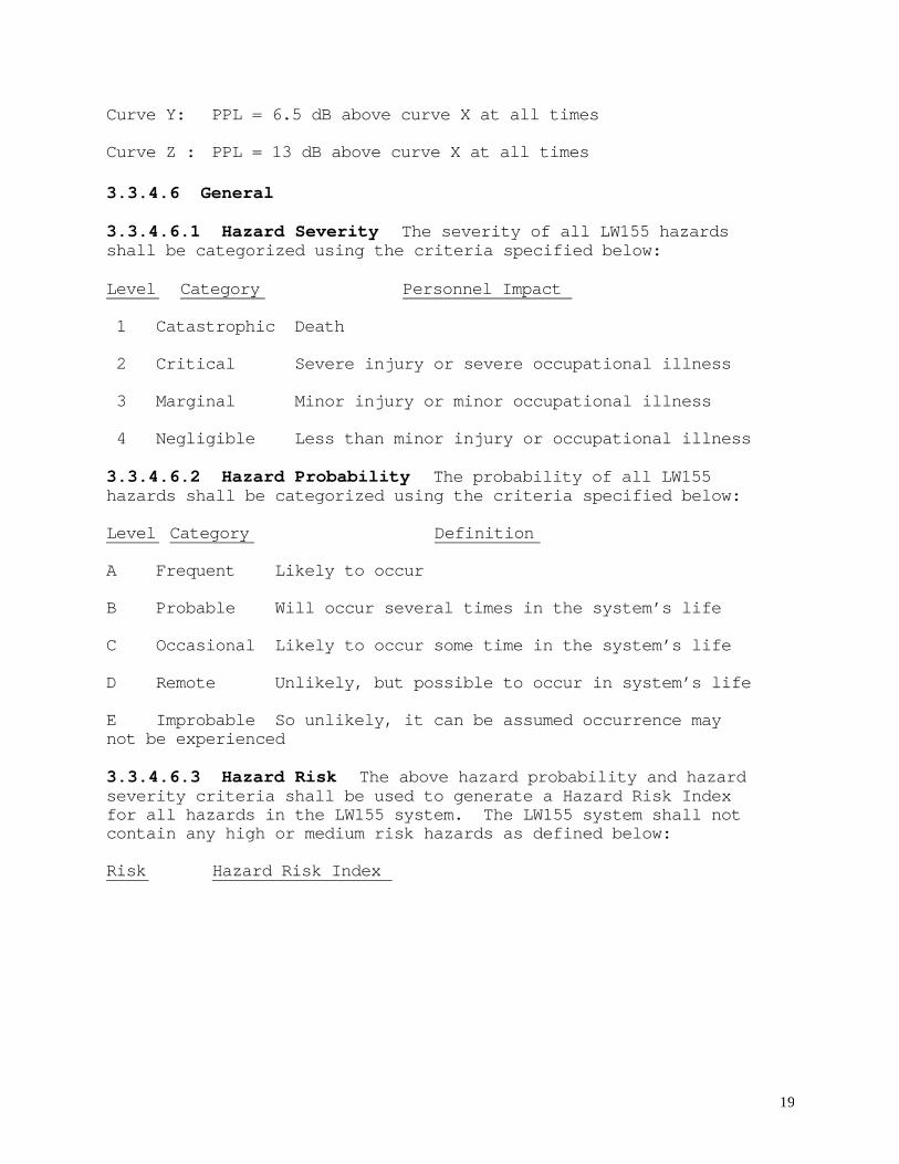
3.3.4.6.1 Hazard Severity The severity of all LW155 hazardsshall be categorized using the criteria specified below:
Level Category Personnel Impact
1 Catastrophic Death
2 Critical Severe injury or severe occupational illness
3 Marginal Minor injury or minor occupational illness
4 Negligible Less than minor injury or occupational illness
3.3.4.6.2 Hazard Probability The probability of all LW155hazards shall be categorized using the criteria specified below:
Level Category Definition
A Frequent Likely to occur
B Probable Will occur several times in the system’s life
C Occasional Likely to occur some time in the system’s life
D Remote Unlikely, but possible to occur in system’s life
E Improbable So unlikely, it can be assumed occurrence maynot be experienced
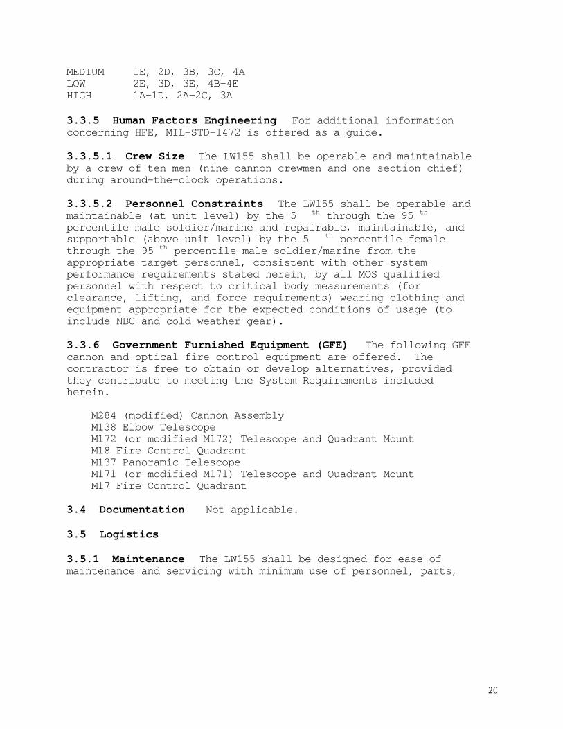
3.3.4.6.3 Hazard Risk The above hazard probability and hazardseverity criteria shall be used to generate a Hazard Risk Indexfor all hazards in the LW155 system. The LW155 system shall notcontain any high or medium risk hazards as defined below:
Risk Hazard Risk Index
20
MEDIUM 1E, 2D, 3B, 3C, 4ALOW 2E, 3D, 3E, 4B-4EHIGH 1A-1D, 2A-2C, 3A
3.3.5 Human Factors Engineering For additional informationconcerning HFE, MIL-STD-1472 is offered as a guide.
3.3.5.1 Crew Size The LW155 shall be operable and maintainableby a crew of ten men (nine cannon crewmen and one section chief)during around-the-clock operations.
3.3.5.2 Personnel Constraints The LW155 shall be operable andmaintainable (at unit level) by the 5 th through the 95 th
percentile male soldier/marine and repairable, maintainable, andsupportable (above unit level) by the 5 th percentile femalethrough the 95 th percentile male soldier/marine from theappropriate target personnel, consistent with other systemperformance requirements stated herein, by all MOS qualifiedpersonnel with respect to critical body measurements (forclearance, lifting, and force requirements) wearing clothing andequipment appropriate for the expected conditions of usage (toinclude NBC and cold weather gear).
3.3.6 Government Furnished Equipment (GFE) The following GFEcannon and optical fire control equipment are offered. Thecontractor is free to obtain or develop alternatives, providedthey contribute to meeting the System Requirements includedherein.
M284 (modified) Cannon Assembly M138 Elbow Telescope M172 (or modified M172) Telescope and Quadrant Mount M18 Fire Control Quadrant M137 Panoramic Telescope M171 (or modified M171) Telescope and Quadrant Mount M17 Fire Control Quadrant
3.4 Documentation Not applicable.
3.5 Logistics
3.5.1 Maintenance The LW155 shall be designed for ease ofmaintenance and servicing with minimum use of personnel, parts,
21
special tools, and equipment. The LW155 shall have similar orreduced support requirements as the predecessor system.
3.5.1.1 Maintenance Equipment
3.5.1.1.1 Tools and Support Equipment The system shall maximizeuse of existing tools and support equipment common to the currentfielded artillery system.
3.5.1.1.2 Automatic Test Equipment (ATE) If Automatic TestEquipment (ATE) is needed, the Integrated Family of TestEquipment (IFTE) will be used by the Army and the Third EchelonTest Set (TETS) will be used by the Marine Corps.
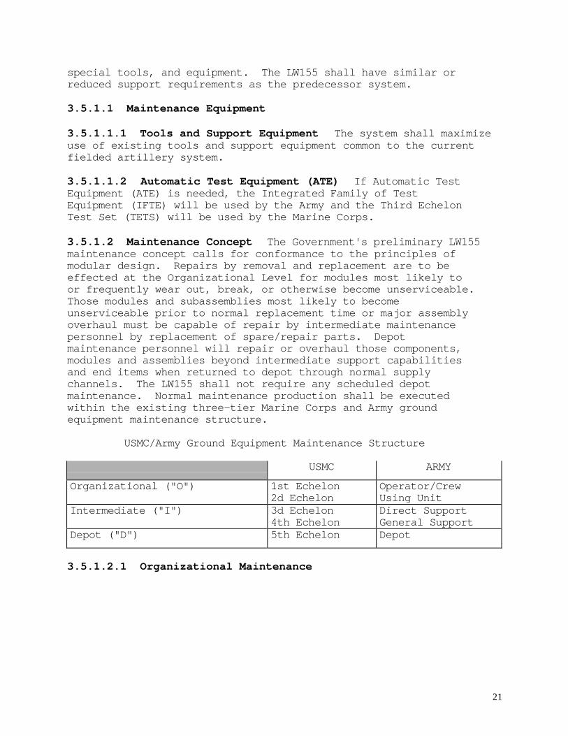
3.5.1.2 Maintenance Concept The Government's preliminary LW155maintenance concept calls for conformance to the principles ofmodular design. Repairs by removal and replacement are to beeffected at the Organizational Level for modules most likely toor frequently wear out, break, or otherwise become unserviceable.Those modules and subassemblies most likely to becomeunserviceable prior to normal replacement time or major assemblyoverhaul must be capable of repair by intermediate maintenancepersonnel by replacement of spare/repair parts. Depotmaintenance personnel will repair or overhaul those components,modules and assemblies beyond intermediate support capabilitiesand end items when returned to depot through normal supplychannels. The LW155 shall not require any scheduled depotmaintenance. Normal maintenance production shall be executedwithin the existing three-tier Marine Corps and Army groundequipment maintenance structure.
USMC/Army Ground Equipment Maintenance Structure
USMC ARMY
Organizational ("O") 1st Echelon2d Echelon
Operator/CrewUsing Unit
Intermediate ("I") 3d Echelon4th Echelon
Direct SupportGeneral Support
Depot ("D") 5th Echelon Depot
3.5.1.2.1 Organizational Maintenance
22
3.5.1.2.1.1 Operator/Crew Maintenance is performed by theuser(s) of the equipment, it includes the proper care, use,operation, cleaning, preservation, lubrication and suchadjustment, minor repair, testing, and parts replacementprescribed by pertinent technical publications, tools and partsallowances. As a reference to the baseline M198 towed howitzer,the following MOS’s perform maintenance at this level. In theMarine Corps, maintenance is accomplished by MOS 0811 FieldArtillery Cannoneer and 0802 Field Artillery Officer. In theArmy, maintenance is accomplished by MOS 13B Cannon Crew Member.
3.5.1.2.1.2 Unit Maintenance is performed by specially trainedpersonnel assigned to the unit. Appropriate publicationsauthorize additional tools and necessary parts, supplies, testequipment, and skilled personnel to perform maintenance beyondthe capabilities and facilities of Operator/Crew levelmaintenance. Efforts at this level encompass performance ofscheduled/corrective maintenance; diagnosis and isolation ofeasily traced equipment malfunctions; replacement of majorassemblies/modular components which can be removed/installed anddo not require critical adjustment; and replacement of readilyaccessible piece parts not authorized at first echelon. As areference to the baseline M198 towed howitzer, the followingMOS’s perform maintenance at this level. In the Marine Corps,maintenance is accomplished by MOS 2131 Towed Artillery SystemsTechnician and 2120 Weapon Repair Officer. In the Army,maintenance is accomplished by MOS 13BU6 Cannon Crew Member, and63B Light-Wheeled Vehicle Mechanic.
3.5.1.2.2 Intermediate Maintenance This is maintenanceperformed by designated activities in direct and general supportof using organizations. It includes calibration and repair andreplacement of damaged or unserviceable parts, and providestechnical assistance support through a secondary repairable floatand/or contact team support to using organizations. For example,the Ordnance Maintenance Company of the Marine Force ServiceSupport Group (FSSG) or Army Division Support Command providesintermediate maintenance services to its respective artilleryorganizations (Marine Artillery Regiment/DivArty), including thatfor fire control optics equipment. A similar activity does thesame for Army artillery units. Intermediate maintenance normallyentails third and fourth echelon services and, when supportingoverflow organizational requirements, includes second echelon as

23
well. As a reference to the baseline M198 towed howitzer, thefollowing MOS’s perform maintenance at this level. In the MarineCorps, maintenance is accomplished by MOS 2131, Towed ArtillerySystems Technician, 2120 Weapon Repair Officer, 2171 Electric-Optical Technician, 2125 Electric-Optical Repair Officer, 1316Metal Worker, and 2161 Machinist. In the Army, maintenance isaccomplished by MOS 45B10 Small Arms/Towed Artillery Repairer,45G10 Fire Control Systems Repairer, 45K30 Armament RepairSupervisor, 913A Armament Repair Technician, 91B OrdnanceMaintenance Management Officer, and 63B Organizational LightWheeled Vehicle Mechanic.
3.5.1.2.2.1 Direct Support Maintenance is authorized byappropriate publications and performed by specially trainedpersonnel, it includes diagnostic and isolation ofequipment/modular malfunctions; adjustment and alignment ofmodules using test, measurement, and diagnostic equipment (TMDE);repair by replacement of modular components and piece parts whichdo not require extensive post-maintenance testing or adjustment;limited repair of modular components requiring cleaning, sealreplacement, application of minor body work and evaluation ofemissions of internal combustion engines.
3.5.1.2.2.2 General Support This level of maintenance isnormally associated with the semi-fixed or permanent generalsupport shops of Intermediate Maintenance Activities (IMAs) orfrequently with organizational shops of units with a commoditypeculiar mission. Work involves diagnosis, isolation,adjustment, calibration, alignment, and repair of malfunctions tothe internal piece part level; replacement of defective modularcomponents not authorized at lower levels; repair of majormodular components by grinding or adjusting items; replacinginternal and external piece parts; and performance of certaincarriage and recoil mechanism repairs.
3.5.1.2.3 Depot Maintenance Depot level personnel perform majoroverhaul or complete rebuild of parts, subassemblies, assemblies,or end items, including the manufacture of parts and performanceof required modifications, testing, and reclamation. Depotmaintenance serves to support lower categories of maintenance byproviding technical assistance and performing maintenance beyondtheir responsibility. Depot Maintenance Activities (DMAs) havemore extensive repair facilities and employ production and
24
assembly line methods whenever practical as well as wholesalelevel direct exchange support.
3.5.2 Support The system shall be supportable by the standardArmy Logistics System as well as the current maintenance policiesin effect within the USMC at the time of fielding.
3.5.3 Facilities No new facilities shall be required. Basingand associated facility requirements shall not change from thepredecessor system.
3.6 Personnel
3.6.1 MOS The system shall have no new Military OccupationalSpecialty (MOS). MOS 13B (Army) and MOS 0811 (USMC) personnelshall be the primary operators of the LW155.
3.6.2 Force Requirements There shall be no new forcerequirements. The total number of authorized maintainers andsupporters shall not increase above what is required for the M198baseline system.
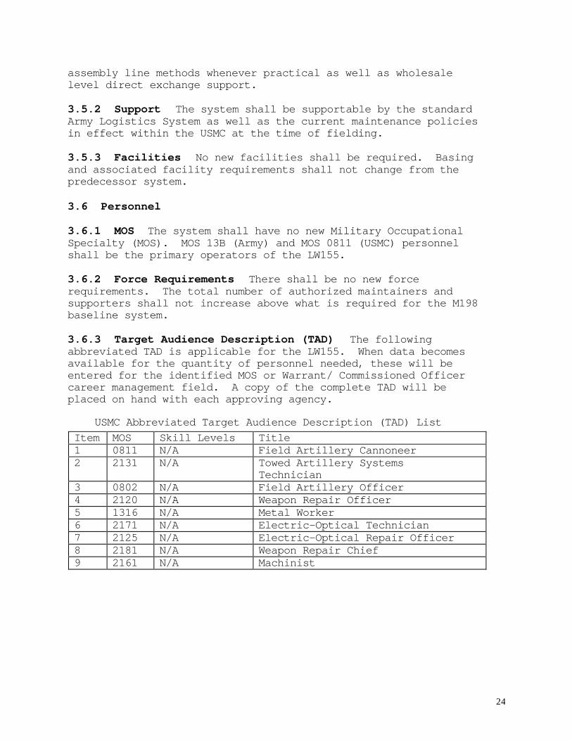
3.6.3 Target Audience Description (TAD) The followingabbreviated TAD is applicable for the LW155. When data becomesavailable for the quantity of personnel needed, these will beentered for the identified MOS or Warrant/ Commissioned Officercareer management field. A copy of the complete TAD will beplaced on hand with each approving agency.
USMC Abbreviated Target Audience Description (TAD) ListItem MOS Skill Levels Title1 0811 N/A Field Artillery Cannoneer2 2131 N/A Towed Artillery Systems
Technician3 0802 N/A Field Artillery Officer4 2120 N/A Weapon Repair Officer5 1316 N/A Metal Worker6 2171 N/A Electric-Optical Technician7 2125 N/A Electric-Optical Repair Officer8 2181 N/A Weapon Repair Chief9 2161 N/A Machinist
25
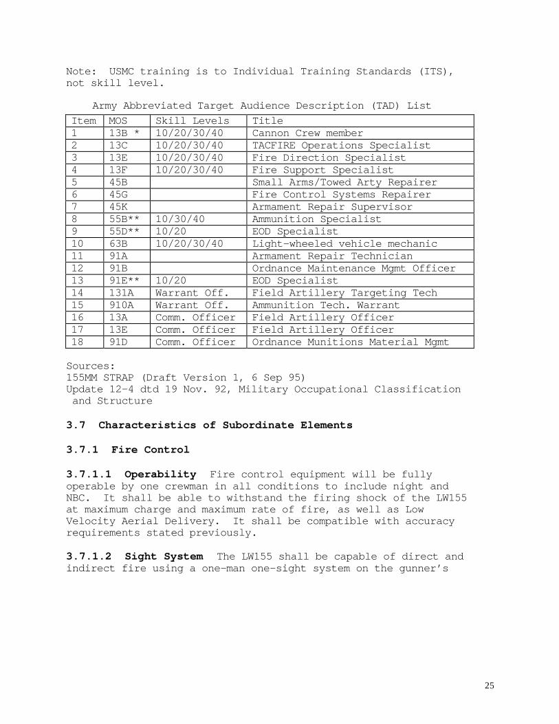
Note: USMC training is to Individual Training Standards (ITS),not skill level.
Army Abbreviated Target Audience Description (TAD) ListItem MOS Skill Levels Title1 13B * 10/20/30/40 Cannon Crew member2 13C 10/20/30/40 TACFIRE Operations Specialist3 13E 10/20/30/40 Fire Direction Specialist4 13F 10/20/30/40 Fire Support Specialist5 45B Small Arms/Towed Arty Repairer6 45G Fire Control Systems Repairer7 45K Armament Repair Supervisor8 55B** 10/30/40 Ammunition Specialist9 55D** 10/20 EOD Specialist10 63B 10/20/30/40 Light-wheeled vehicle mechanic11 91A Armament Repair Technician12 91B Ordnance Maintenance Mgmt Officer13 91E** 10/20 EOD Specialist14 131A Warrant Off. Field Artillery Targeting Tech15 910A Warrant Off. Ammunition Tech. Warrant16 13A Comm. Officer Field Artillery Officer17 13E Comm. Officer Field Artillery Officer18 91D Comm. Officer Ordnance Munitions Material Mgmt
Sources:155MM STRAP (Draft Version 1, 6 Sep 95)Update 12-4 dtd 19 Nov. 92, Military Occupational Classification and Structure
3.7 Characteristics of Subordinate Elements
3.7.1 Fire Control
3.7.1.1 Operability Fire control equipment will be fullyoperable by one crewman in all conditions to include night andNBC. It shall be able to withstand the firing shock of the LW155at maximum charge and maximum rate of fire, as well as LowVelocity Aerial Delivery. It shall be compatible with accuracyrequirements stated previously.
3.7.1.2 Sight System The LW155 shall be capable of direct andindirect fire using a one-man one-sight system on the gunner’s
26
(left) side. [On the M198 howitzer, direct fire with the one-manone-sight system (M137 sight) should be performed only when thegun and target are at the same elevation, with no mask obstaclesbetween them.] The gunner shall set and/or read deflection andelevation by use of a display, readily visible from the left sideelevation and traverse handwheels. The assistant gunner shall beable to set and/or read elevation by a separate display, readilyvisible from the right side elevation handwheel.
3.7.1.3 Boresighting It shall be possible for the LW155 crew toverify boresight as part of emplacement procedures. If boresightis out of tolerance (0.5 mil) the crew shall be able to boresightthe weapon system tactically without the need for an externalreference point.
3.7.1.4 Cant The fire control equipment shall be able tocompensate for up to ten degrees of cant left or right of theweapon’s level point.
3.7.2 Cannon Assembly
3.7.2.1 Chamber Temperature The LW155 shall have a visualsensor to determine chamber temperature to assist the crew indetermining misfire procedures and rate of fire limitations.
3.7.2.2 Ignition System The LW155 shall have a reliable,improved ignition system that accommodates the firing ratesspecified in 3.2.2.3. It shall be designed so that the systemwill not ignite the propellant until the breech is closed andlocked (witness marks aligned). Additionally, the propellantignition system shall provide for a minimum of eight (threshold)to 30 (objective) ignitions without reloading by a crew member.
3.7.2.3 Breech Operation The LW155 breech shall openautomatically after firing. The breech shall have inscribedalignment (witness) marks to provide a visual indication ofbreech closure.
3.7.3 Elevation Mechanism When fully emplaced and settled intoposition on level terrain, the LW155 shall be capable of settinga minimum elevation of zero mils or less and a maximum elevationof at least 1275 mils. The LW155 shall be able to fire allcharges (except the M119 and M203 series charges) throughout its
27
full range of elevation. The minimum elevation for the M119 andM203 series charges shall be no greater than 300 mils. The LW155shall be able to fire all allowable charge/elevation anddeflection combinations on a surface with up to plus or minus tendegrees of cant. The howitzer shall not require a recoil pit forany allowable elevation and charge combination. An elevationhandwheel is required on both the right and left side of thehowitzer. The manual elevating mechanisms shall obtain at leastten (threshold) to fifteen (objective) mils of movement perhandwheel turn. The equipment shall allow for simultaneousmovement of the weapon for deflection and elevation during layingprocedures.
3.7.4 Traversing Mechanism The LW155 shall be capable of firingwith an on-carriage traverse capability of at least 400 mils leftand right of center through the full elevation range. A manualtraversing mechanism is required. It shall obtain at least ten(threshold) to fifteen (objective) mils of movement per handwheelturn. The equipment shall allow for simultaneous movement of theweapon for deflection and elevation during laying procedures.
3.7.5 Hydraulic Fluid The LW155 system shall be designed toemploy a single, flame resistant, hydraulic fluid. Anyadditional hydraulic fluids proposed will require Governmentauthorization prior to being implemented.
3.8 Precedence of Requirements
1. Maximum Weight 2. Responsiveness 3. Transportability/Mobility 4. Lethality 5. Vulnerability/Survivability 6. Maintainability/Sustainability
4.0 QUALITY ASSURANCE PROVISIONS
4.1 Responsibility for Compliance The contractor shall beresponsible for assuring compliance with all the requirementsspecified herein prior to delivery of the system to theGovernment. The Government reserves the right to perform anyaction deemed necessary to assure the system conforms to thisspecification prior to delivery to the Government.
28
4.2 Responsibility for Inspection The contractor shall beresponsible for certifying that all components comply with allapplicable configuration control documentation prior toevaluating conformance.
4.3 Requirements Cross Reference This section establishes thespecific evaluation criteria for verifying the performancerequirements specified in section 3 herein. The individualrequirements cross reference verification methods are provided inmatrix form at Appendix B. This matrix indicates theverification method, level, and responsible authority (contractorversus Government) required to certify compliance to each section3 requirement. Each section 3 requirement is associated with asection 4 verification method.
4.3.1 Verification Methods A brief description of theverification methods as they apply to this specification isprovided below:
4.3.1.1 Examination A visual inspection which may involve thereview of the part and its respective installation, as well asits associated drawings, specifications, Quality AssuranceProvisions and purchase orders to the extent necessary toestablish compliance.
4.3.1.2 Analysis A review of data/information produced as aresult of analytical computations, qualitative assessments, ortests conducted for another purpose.
4.3.1.3 Demonstration A non-instrumented test where success isdetermined on the basis of observation or the use of simple testequipment.
4.3.1.4 Test An instrumented formal quantitative measurement ofspecific system parameters using certified test equipment. Thisverification method may require analysis to interpret result.
4.3.2 Verification Levels A brief description of theverification levels as they apply to this specification isprovided below:
4.3.2.1 System A complete LW155 howitzer.
29
4.3.2.2 Subsystem A complete hardware configuration item withuniquely identifiable performance requirements.
4.3.2.3 Component An assembly or piece-part of a subsystem withuniquely identifiable performance requirements.
4.3.3 Verification Responsibility A brief description of theverification responsibilities as they apply to this specificationis provided below.
4.3.3.1 Government The Government shall be overall responsiblefor ensuring formal verification is completed, with technicalassistance and on-site support by the contractor.
4.3.3.2 Contractor The contractor shall be responsible forperforming the formal verification. The Government reserves theright to provide on-site representation to monitor and verify theresults.
5.0 ACRONYMS AND DEFINITIONS
5.1 List of Acronyms
AAAV Advanced Amphibious Assault VehicleAAL Additional Authorized ListAAR American Association of RailroadsABCS Army Battle Command and Control SystemABS Anti-lock Brake SystemAC Active ComponentAFATDS Advanced Field Artillery Tactical Data SystemAMSAA Army Material Systems Analysis ActivityAPS Auxiliary Power SystemARDEC Armaments Research, Development, and Engineering
CenterARL Army Research LaboratoryARTEP Army Training and Evaluation ProgramATCAS Advanced Towed Cannon SystemATE Automatic Test EquipmentBCS Battery Computer SystemBDAR Battle Damage Assessment and RepairBII Basic Issue ItemsBIT Built In Test

30
BITE Built In Test EquipmentC2 Command and ControlC3 Command, Control and CommunicationCATT Combined Arms Tactical TrainerCCTT Close Combat Tactical TrainerCEP Circular Error ProbableCLS Contract Logistical SupportCOEA Cost and Operational Effectiveness AnalysisCOIC Critical Operational Issues and CriteriaCOMPUSEC Computer SecurityCOMSEC Communications SecurityCTC Combat Training CenterCTCITS Combat Training Center Instrumentation and
Training SystemDC Direct CurrentDCD Directorate of Combat DevelopmentDIS Distributed Interactive SimulationDOD Department of DefenseDOT Department of TransportationDOT&E Developmental Operational Test and EvaluationDPICM Dual Purpose Improved Conventional MunitionsDRMP Design Reference Mission ProfileDS Direct SupportDTT Doctrine and Tactics TrainingEAP Equipment Allowance PoolECM Electronic CountermeasureEFC Equivalent Full ChargeEMD Engineering and Manufacturing DevelopmentET Embedded TrainingEUMD Essential Unscheduled Maintenance DemandsEUT Early User TestFAE Fuel Air ExplosivesFAMSIM Family of SimulationsFDC Fire Direction CenterFDTE Force Development Test and ExperimentationFLOT Forward Line of TroopsFMC Fully Mission CapableFMTV Family of Medium Tactical VehiclesFOC Final Operational CapabilityFOT Follow On TestFSAC Fire Support Armaments CenterFSCATT Fire Support Combined Arms Tactical TrainerFUE First Unit Equipped
31
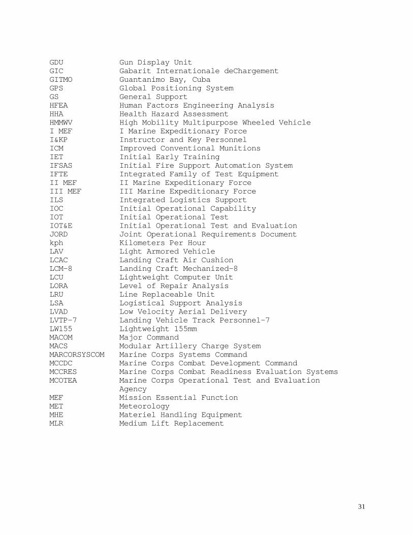
GDU Gun Display UnitGIC Gabarit Internationale deChargementGITMO Guantanimo Bay, CubaGPS Global Positioning SystemGS General SupportHFEA Human Factors Engineering AnalysisHHA Health Hazard AssessmentHMMWV High Mobility Multipurpose Wheeled VehicleI MEF I Marine Expeditionary ForceI&KP Instructor and Key PersonnelICM Improved Conventional MunitionsIET Initial Early TrainingIFSAS Initial Fire Support Automation SystemIFTE Integrated Family of Test EquipmentII MEF II Marine Expeditionary ForceIII MEF III Marine Expeditionary ForceILS Integrated Logistics SupportIOC Initial Operational CapabilityIOT Initial Operational TestIOT&E Initial Operational Test and EvaluationJORD Joint Operational Requirements Documentkph Kilometers Per HourLAV Light Armored VehicleLCAC Landing Craft Air CushionLCM-8 Landing Craft Mechanized-8LCU Lightweight Computer UnitLORA Level of Repair AnalysisLRU Line Replaceable UnitLSA Logistical Support AnalysisLVAD Low Velocity Aerial DeliveryLVTP-7 Landing Vehicle Track Personnel-7LW155 Lightweight 155mmMACOM Major CommandMACS Modular Artillery Charge SystemMARCORSYSCOM Marine Corps Systems CommandMCCDC Marine Corps Combat Development CommandMCCRES Marine Corps Combat Readiness Evaluation SystemsMCOTEA Marine Corps Operational Test and Evaluation
AgencyMEF Mission Essential FunctionMET MeteorologyMHE Materiel Handling EquipmentMLR Medium Lift Replacement
32
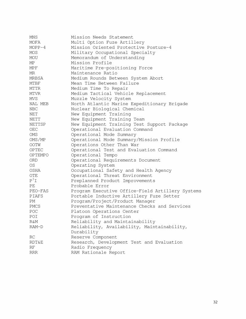
MNS Mission Needs StatementMOFA Multi Option Fuze ArtilleryMOPP-4 Mission Oriented Protective Posture-4MOS Military Occupational SpecialtyMOU Memorandum of UnderstandingMP Mission ProfileMPF Maritime Pre-positioning ForceMR Maintenance RatioMRBSA Medium Rounds Between System AbortMTBF Mean Time Between FailureMTTR Medium Time To RepairMTVR Medium Tactical Vehicle ReplacementMVS Muzzle Velocity SystemNAL MEB North Atlantic Marine Expeditionary BrigadeNBC Nuclear Biological ChemicalNET New Equipment TrainingNETT New Equipment Training TeamNETTSP New Equipment Training Test Support PackageOEC Operational Evaluation CommandOMS Operational Mode SummaryOMS/MP Operational Mode Summary/Mission ProfileOOTW Operations Other Than WarOPTEC Operational Test and Evaluation CommandOPTEMPO Operational TempoORD Operational Requirements DocumentOS Operating SystemOSHA Occupational Safety and Health AgencyOTE Operational Threat EnvironmentP3I Preplanned Product ImprovementsPE Probable ErrorPEO-FAS Program Executive Office-Field Artillery SystemsPIAFS Portable Inductive Artillery Fuze SetterPM Program/Project/Product ManagerPMCS Preventative Maintenance Checks and ServicesPOC Platoon Operations CenterPOI Program of InstructionR&M Reliability and MaintainabilityRAM-D Reliability, Availability, Maintainability,
DurabilityRC Reserve ComponentRDT&E Research, Development Test and EvaluationRF Radio FrequencyRRR RAM Rationale Report
33
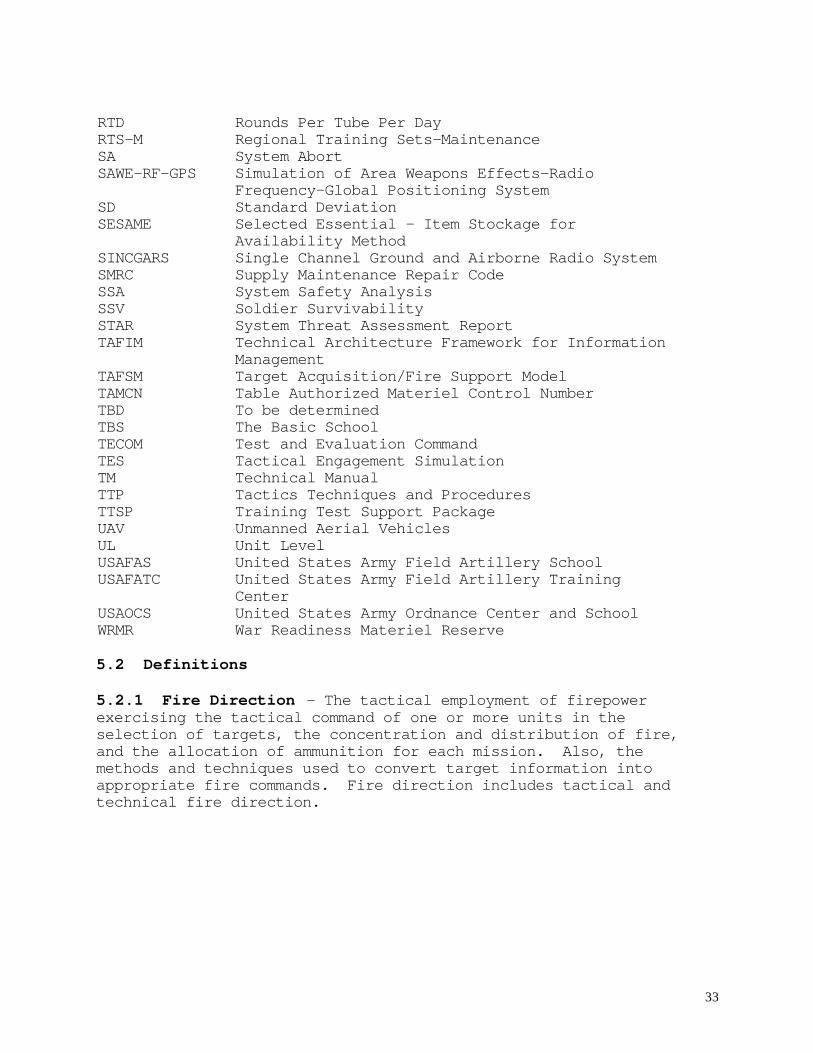
RTD Rounds Per Tube Per DayRTS-M Regional Training Sets-MaintenanceSA System AbortSAWE-RF-GPS Simulation of Area Weapons Effects-Radio
Frequency-Global Positioning SystemSD Standard DeviationSESAME Selected Essential - Item Stockage for
Availability MethodSINCGARS Single Channel Ground and Airborne Radio SystemSMRC Supply Maintenance Repair CodeSSA System Safety AnalysisSSV Soldier SurvivabilitySTAR System Threat Assessment ReportTAFIM Technical Architecture Framework for Information
ManagementTAFSM Target Acquisition/Fire Support ModelTAMCN Table Authorized Materiel Control NumberTBD To be determinedTBSTECOM
The Basic SchoolTest and Evaluation Command
TES Tactical Engagement SimulationTM Technical ManualTTP Tactics Techniques and ProceduresTTSP Training Test Support PackageUAV Unmanned Aerial VehiclesUL Unit LevelUSAFAS United States Army Field Artillery SchoolUSAFATC United States Army Field Artillery Training
CenterUSAOCS United States Army Ordnance Center and SchoolWRMR War Readiness Materiel Reserve
5.2 Definitions
5.2.1 Fire Direction - The tactical employment of firepowerexercising the tactical command of one or more units in theselection of targets, the concentration and distribution of fire,and the allocation of ammunition for each mission. Also, themethods and techniques used to convert target information intoappropriate fire commands. Fire direction includes tactical andtechnical fire direction.
34
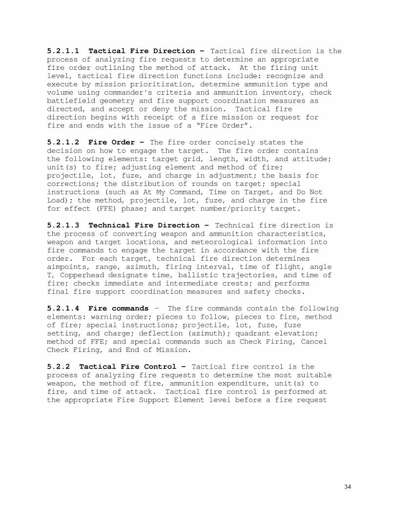
5.2.1.1 Tactical Fire Direction - Tactical fire direction is theprocess of analyzing fire requests to determine an appropriatefire order outlining the method of attack. At the firing unitlevel, tactical fire direction functions include: recognize andexecute by mission prioritization, determine ammunition type andvolume using commander's criteria and ammunition inventory, checkbattlefield geometry and fire support coordination measures asdirected, and accept or deny the mission. Tactical firedirection begins with receipt of a fire mission or request forfire and ends with the issue of a “Fire Order”.
5.2.1.2 Fire Order - The fire order concisely states thedecision on how to engage the target. The fire order containsthe following elements: target grid, length, width, and attitude;unit(s) to fire; adjusting element and method of fire;projectile, lot, fuze, and charge in adjustment; the basis forcorrections; the distribution of rounds on target; specialinstructions (such as At My Command, Time on Target, and Do NotLoad); the method, projectile, lot, fuze, and charge in the firefor effect (FFE) phase; and target number/priority target.
5.2.1.3 Technical Fire Direction - Technical fire direction isthe process of converting weapon and ammunition characteristics,weapon and target locations, and meteorological information intofire commands to engage the target in accordance with the fireorder. For each target, technical fire direction determinesaimpoints, range, azimuth, firing interval, time of flight, angleT, Copperhead designate time, ballistic trajectories, and time offire; checks immediate and intermediate crests; and performsfinal fire support coordination measures and safety checks.
5.2.1.4 Fire commands - The fire commands contain the followingelements: warning order; pieces to follow, pieces to fire, methodof fire; special instructions; projectile, lot, fuze, fuzesetting, and charge; deflection (azimuth); quadrant elevation;method of FFE; and special commands such as Check Firing, CancelCheck Firing, and End of Mission.
5.2.2 Tactical Fire Control - Tactical fire control is theprocess of analyzing fire requests to determine the most suitableweapon, the method of fire, ammunition expenditure, unit(s) tofire, and time of attack. Tactical fire control is performed atthe appropriate Fire Support Element level before a fire request
35
is sent to the cannon battalion. As such, tactical fire controlprecedes tactical fire direction. Tactical fire control is oftenincorrectly used synonymously with tactical fire direction.
5.2.3 Fire Control - Fire control is all operations connectedwith the conversion of aiming data (from fire commands and aimingdevices) into pointing the weapon to deliver munitions on target.
5.2.4 Fire Control Equipment - Fire control equipment is theequipment necessary to perform fire control operations. Thisincludes sighting and alignment devices, gun drives, processors,and peripheral equipment necessary to perform boresighting on ahowitzer, as well as the devices required for gun laying ofanother howitzer.

36
REQUIREMENTS CROSS REFERENCE VERIFICATION MATRIX
PARAGRAPH VERIFICATIONMETHOD
LEVELAGENCY
Exam
Anal Demo
Test Sys Sub Com Cont Govt
3.2.2 PerformanceCharacteristics3.2.2.1 Range3.2.2.1.1 MaximumRange
X X X
3.2.2.1.2 MinimumRange
X X X
3.2.2.1.3 RangeOverlap
X X X
3.2.2.2 Bias &Precision3.2.2.2.1 Bias X X X3.2.2.2.2 Precision X X X3.2.2.3 Rate of Fire3.2.2.3.1 MaximumRate of Fire
X X X
3.2.2.3.2 SustainedRate of Fire
X X X
3.2.2.4Responsiveness3.2.2.4.1Emplacement
X X X
3.2.2.4.2Displacement
X X X
3.2.2.4.3 Out ofTraverse
X X X
3.2.2.4.4 LowAngle Fire
X X X
3.2.2.4.5 HighAngle Fire
X X X
3.2.2.5 Direct Fire X X X3.2.2.6 Survivability3.2.2.6.1 NBCProtection
X X X
3.2.2.6.2 BallisticVulnerability
X X X
37
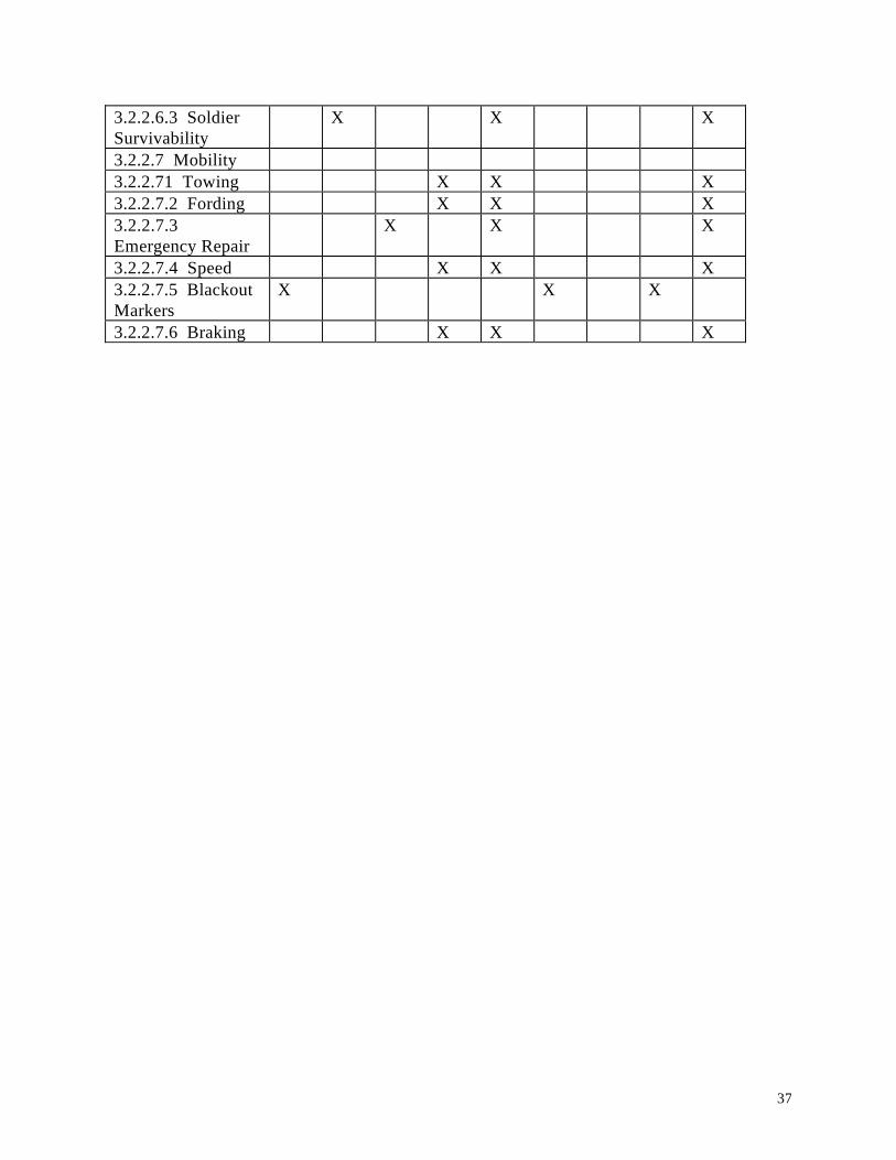
3.2.2.6.3 SoldierSurvivability
X X X
3.2.2.7 Mobility3.2.2.71 Towing X X X3.2.2.7.2 Fording X X X3.2.2.7.3Emergency Repair
X X X
3.2.2.7.4 Speed X X X3.2.2.7.5 BlackoutMarkers
X X X
3.2.2.7.6 Braking X X X

38
REQUIREMENTS CROSS REFERENCE VERIFICATION MATRIX
PARAGRAPH VERIFICATIONMETHOD
LEVELAGENCY
Exam
Anal Demo
Test Sys Sub Com Cont Govt
3.2.2.8Transportability3.2.2.8.1 FixedWing
X X X
3.2.2.8.2 RotaryWing
X X X
3.2.2.8.3 Marine X X X3.2.2.8.4 Highway& Rail
X X X
3.2.2.8.5 Lifting andTiedown Provisions
X X X
3.2.3 ExternalInterfaces3.2.3.1 Ammunition X X X3.2.3.2 PrimeMover Interface
X X X
3.2.3.3 C3 Interface X X X3.2.3.4 Intra-systemInterfaces
X X X
3.2.3.5 PreplannedProductImprovements
X X X
3.2.4 PhysicalCharacteristics3.2.4.1 Weight X X X3.2.4.2 SurfaceFinish
X X X
3.2.5 QualityFactors3.2.5.1 Reliability X X X3.2.5.2Maintainability3.2.5.2.1Operator/CrewPMCS
X X X
3.2.5.2.2 CPC X X X

39
PMCS3.2.5.2.3 MR X X X3.2.5.2.4 UnitMTTR
X X X
3.2.5.2.5 DS MTTR X X X3.2.5.2.6Maintenance Tasks
X X X
3.2.5.2.7Accessibiity
X X X
3.2.5.3 Durability3.2.5.3.1 CannonTube Fatigue Life
X X X
3.2.5.3.2 BreechMechanism FatigueLife
X X X
3.2.5.3.3 RecoilMechanism ServiceLife
X X X
3.2.5.3.4 Carriageand Cradle ServiceLife
X X X

40
REQUIREMENTS CROSS REFERENCE VERIFICATION MATRIX
PARAGRAPH VERIFICATIONMETHOD
LEVEL AGENCY
Exam
Anal Demo
Test Sys Sub Com Cont Govt
3.2.6 Environments3.2.6.1 OperatingEnvironments3.2.6.1.1 Climatic X X X3.2.6.1.2 NaturalEnvironments
X X X
3.2.6.1.3 InducedEnvironments
X X X
3.2.6.2 Non-operatingEnvironment3.2.6.2.1 Climatic X X X3.2.6.2.2 NaturalEnvironments
X X X
3.2.6.2.3 InducedEnvironments
X X X
3.3 Design andConstruction3.3.1 Materials,Processes and Parts3.3.1.1 Materials X X X3.3.1.2 ProcessControl
X X X
3.3.1.3 Standard,commercial andQualified Parts
X X X
3.3.1.4EnvironmentalCompliance
X X X
3.3.1.5 MetricSystem
X X X
3.3.1.6 RadioactiveMatl
X X X
3.3.2 Name Plates &Product Markings
X X X
3.3.3Interchangeability
X X X

41
3.3.4 Safety3.3.4.1 ThermalHazard
X X X
3.3.4.2 NoxiousSubstances
X X X
3.3.4.3 Flammability X X X3.3.4.4 MechanicalSafety

42
REQUIREMENTS CROSS REFERENCE VERIFICATION MATRIX
PARAGRAPH VERIFICATIONMETHOD
LEVELAGENCY
Exam
Anal Demo
Test Sys Sub Com Cont Govt
3.3.4.4.1 EdgeRounding
X X X
3.3.4.4.2Entrapment
X X X
3.3.4.4.3MechanicalInterconnection
X X X
3.3.4.5 ImpulseNoise
X X X
3.3.4.6 General3.3.4.6.1 HazardSeverity
X X X
3.3.4.6.2 HazardProbability
X X X
3.3.4.6.3 HazardRisk
X X X
3.3.5 HumanFactors Engineering3.3.5.1 Crew Size X X X3.3.5.2 PersonnelConstraints
X X X
3.3.6 GFE N/A3.4 Documentation N/A3.5 Logistics3.5.1 Maintenance X X X3.5.1.1 MaintenanceEquipment3.5.1.1.1 Tools andSupport Equipment
X X X
3.5.1.1.2 ATE X X X3.5.1.2 MaintenanceConcept3.5.1.2.1OrganizationalMaintenance3.5.1.2.1.1 X X X
43
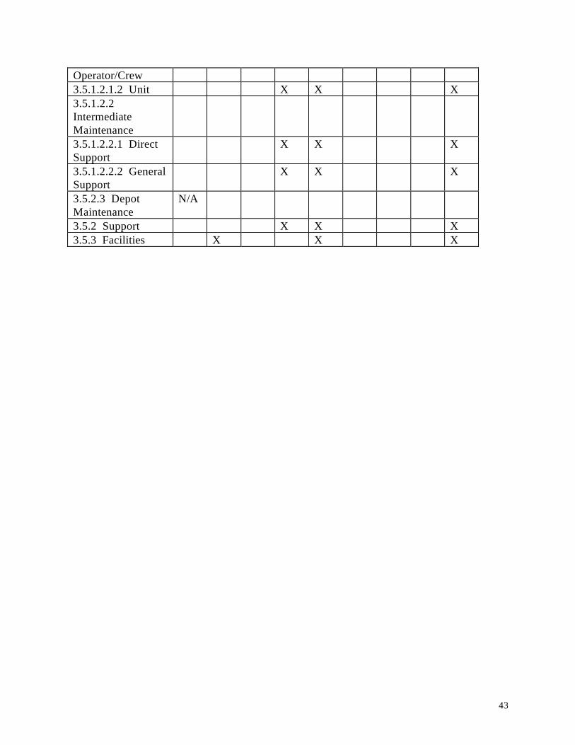
Operator/Crew3.5.1.2.1.2 Unit X X X3.5.1.2.2IntermediateMaintenance3.5.1.2.2.1 DirectSupport
X X X
3.5.1.2.2.2 GeneralSupport
X X X
3.5.2.3 DepotMaintenance
N/A
3.5.2 Support X X X3.5.3 Facilities X X X
44
3.6 Personnel X X X3.6.1 MOS X X X
REQUIREMENTS CROSS REFERENCE VERIFICATION MATRIX
PARAGRAPH VERIFICATIONMETHOD
LEVELAGENCY
Exam
Anal Demo
Test Sys Sub Com Cont Govt
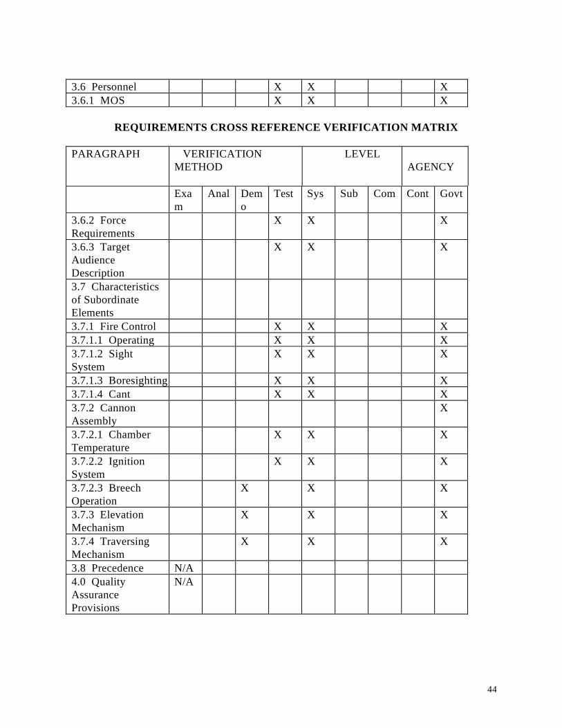
3.6.2 ForceRequirements
X X X
3.6.3 TargetAudienceDescription
X X X
3.7 Characteristicsof SubordinateElements3.7.1 Fire Control X X X3.7.1.1 Operating X X X3.7.1.2 SightSystem
X X X
3.7.1.3 Boresighting X X X3.7.1.4 Cant X X X3.7.2 CannonAssembly
X
3.7.2.1 ChamberTemperature
X X X
3.7.2.2 IgnitionSystem
X X X
3.7.2.3 BreechOperation
X X X
3.7.3 ElevationMechanism
X X X
3.7.4 TraversingMechanism
X X X
3.8 Precedence N/A4.0 QualityAssuranceProvisions
N/A

45
46
ATTACHMENT 1
ENHANCEMENTS/PRE-PLANNED PRODUCT IMPROVEMENTS
A.1 Rearm Device (Army only) The LW155 prime mover shall beequipped with a rearm device to permit the safe transfer ofrounds and propelling charges from the cargo bed of the truck tothe vicinity of the weapon. The ammunition shall be transferredin a safe and controlled manner and shall accommodate ease ofloading and the maximum rate of fire. The same device shall alsobe used to transfer ammunition from a resupply vehicle to theLW155 prime mover when bulk ammunition transfer is not feasible.
A.2 Advanced Digital Fire Control To support the goals of ForceXXI and the digitization of the battlefield, the Army requiresthat the LW155 have the capabilities listed below. The USMC mayprocure these items as P 3I.
A.2.1 Capabilities
A.2.1.1 Fire Control capable of:
(a) Conducting technical fire direction.(b) Self locating to not more than 10 meters horizontal circularerror probable (CEP) and not more than 10 meters verticalprobable error (PE) for all combat conditions and distancestraveled.(c) Determining and displaying direction and orientation of thehowitzer to at least 1 mil Standard Deviation (SD) accuracy, anddetermining and displaying elevation to not less than 0.5 mil SDaccuracy.(d) Providing continuously updated location data while the LW155is moving. The system will not require stopping to maintain therequired accuracies if satellite signals are not temporarilylost for more than four minutes.(e) Dismounting the system locating device to permit the LW155to determine its position using reverse polar plot ortriangulation techniques when satellite reception is inadequatefrom the howitzer position.(f) Receiving data from, and automatically interfacing with, theon-board computer described below, the IFSAS, AFATDS, BCS, LCU,and their developmental replacements.(g) Operating in air transport and marine modes.
47
ATTACHMENT 1
A.2.1.2 On-board computer including:
(a) Determining ballistic solutions (including for NATO standardmunitions) and displaying firing data, selectable as eitherdeflection or azimuth, for any fire mission.(b) Receiving muzzle velocity data from the M93/M94 MuzzleVelocity System (MVS). Automatically managing muzzle velocityvariants, to include digitally transmitting to designatedsubscribers.(c) Receiving and storing up to 15 (threshold) to 30 (objective)preplanned fire missions or targets with all methods of controland attack.(d) Receiving, formatting and transmitting messages compatiblewith the current version of IFSAS/BCS/AFATDS software, and beupdatable at unit level. Shall be upgradable as IFSAS/BCS/AFATDSsoftware is upgraded.(e) Fully interfacing by wire and combat net radio with otherLW155 computers and automated C 2 equipment at battery and higherlevels, to include their developmental replacements.Additionally, the LW155 computer/radio interface shall be capableof automatically retransmitting messages over wire or radio.(f) Interfacing with and providing fuze data to the PortableInductive Artillery Fuze Setter (PIAFS).(g) Accepting input of firing safety data and alerting the crewwhen violated.(h) Managing, displaying and digitally transmitting todesignated subscribers the ammunition inventory for both theresident and a second howitzer.(i) Computing and applying boresight corrections for the entirearc of elevation.(j) Receiving meteorological messages, computing and applyingmeteorological corrections.(k) Interfacing with a hand-held display that allows the sectionchief to manually enter data and verify current gun settings.(l) Automatically measuring and compensating for the effects ofcant in the ballistic computations for fire missions.(m) Include at least 200 percent excess capacity relative topresent memory requirements.(n) Intefacing with a PC-based “panel trainer” device, which maybe required for digital fire control training.
48
ATTACHMENT 1
A.2.1.3 Data displays integrated with the self-locating systemand the on-board computer. The gunner’s display shall displaycurrent elevation and deflection, and firing elevation anddeflection. The assistant gunner’s display shall display currentelevation and firing elevation.
A.2.1.4 A direct fire sight that shall provide a first round hitprobability of 0.30 (threshold) to 0.80 (objective) at 1500meters against stationary NATO standard sized (2.3 by 2.3 meters)targets firing the M107 projectile and charge 7 white bags). Itshall also facilitate tracking of moving targets to include aneasy method to determine and set “leads”, and provide night/poorvisibility enhancement. This may be integrated with theballistic computer.
A.2.1.5 A self-contained power supply capable of operationswithout servicing or recharging for at least six (threshold) to10 (objective) hours at surge intensities as per the OperationalMode Summary/Mission Profile (OMS/MP). This power supply shall:
(a) If needed, be compatible with and rechargeable by the primemover and alternate AC and DC power sources.(b) Meet United States Air Force cargo specifications.(c) If needed, be rech argeable on the move by the prime mover.
A.2.2 Embedded Training The LW155 automated fire control shallhave an Embedded Training (ET) capability which shall be adequateto conduct pretest training for operational testing. Thistraining capability along with training devices mentioned aboveshall be adequate for fielding and sustainment of the LW155. TheET system shall be transparent to the crew as a result of systemhardware/software design. The ET system shall be interoperablewith the Combat Training Center instrumentation and trainingsystems (e.g. MILES, 2000, SAWE-RF) for gunnery training and forensuring effective and responsive collective training for theLW155. An electronic interface between FSCATT and LW155 isrequired.
A.2.3 Computer Security (COMPUSEC) Protection of the computerresources shall be IAW prescribed regulations. Risk analysis andoperating The Fire Support Combined Arms Tactical Trainer(FSCATT) shall be used approvals shall be predefined for both
49
ATTACHMENT 1
operational systems and support facilities to ensure compliancein garrison and to facilitate future determination at anydeployed location.
A.2.4 Weight The weight of the advanced digital fire controlspecified herein does not count against the 9,000 pound thresholdbasic weight, but shall have a combined weight of not more than500 (threshold) to 200 (objective) pounds.
A.2.5 Bias The combination of the materiel requirements of theself-contained system and the on-board computer as noted aboveshall achieve a bias circular error probable (CEP) of 160 meters(threshold) to 50 meters (objective) at 25 kilometers. This isbased upon a two hour MET with 20 kilometer spatial separationfrom the MET station to the midpoint of the trajectory, firingthe M864 projectile at low angle with the maximum charge, and atarget location accuracy of 10 meters.
A.2.6 Degraded Operations The LW155 shall have built in manualbackups to allow continued operation of the howitzer should theprimary systems (prime mover and on-board electronics) fail ornot be available.
A.2.6.1 Power Loss. There shall be a manual back-up for allsystems that require power, except the M93/M94 MVS and on-boardcomputer. Other requirements remain unchanged.
A.2.6.2 Power Loss/Self-locating System Failure. The opticalfire control equipment shall be maintained as a backup capabilityand shall be able to operate independently of the automated firecontrol system.
A.2.6.3 On-board Computer Failure. The LW155 will be capable ofreceiving and displaying digital fire commands which are receivedby wire and radio.
A.2.6.4 Secondary Functions. The LW155 will be capable ofperforming the following functions for a second degradedhowitzer:

50
ATTACHMENT 1
A.2.6.4.1 Radio Failure. Relaying via wire digitaltransmissions from designated subscribers to the second howitzer.
A.2.6.4.2 Computer/Radio Failure. Conducting technical firedirection and transmitting fire commands via wire.
A.2.6.4.3 Computer Failure. Maintaining howitzer status filessuch as howitzer location and azimuth of fire, ready status,muzzle velocities, and ammunition inventories.
A.2.6.4.4 Self-locating System Failure. Reciprocally laying anddetermining location within line of sight
A.2.6.5 Nuclear Effects All LW155 mission essential electronicsshall be survivable to nuclear effects (High AltitudeElectromagnetic Pulse at a minimum). The LW155 shall besurvivable for battlefield electronic warfare threats such asDirected Energy, High Powered Microwave and non-nuclearElectromagnetic Pulse designed to destroy electronic systems suchas communications, fire control, navigation, data processing andcomputers. All LW155 electronics shall be survivable consistentwith developmental Field Artillery C 3 data systems.
A.2.6.6 Unique Requirements Any computer hardware/softwaredeveloped or fielded for the LW155 shall be in accordance withthe open system architecture and standards as specified in theDOD Technical Architecture.
A.3 On-Carriage Loading Device The LW155 design shall allow forthe addition of an on-carriage loading device that shall achievea consistently positive ram at all elevations with humaninterface of no more than one crewman. A backup manual rammingcapability will be maintained. The loading device will notinterfere manual ramming.
A.4 Powered Elevation and Traverse The LW155 design shall allowfor the addition of powered elevation and deflection assists. Abackup manual elevation and traverse capability will bemaintained. The powered assists will not interfere with manualelevation and traverse.
51
ATTACHMENT 1
A.5 BIT/BITE Built-In Test (BIT) and Built-In Test Equipment(BITE) shall be used to successfully fault isolate to the singleLine Replaceable Unit (LRU) 90 percent (threshold) to 95 percent(objective) of the time.
A.6 Electromagnetics
A.6.1 Hardening The LW155 shall be designed to controlelectromagnetic emissions and susceptibility characteristics ofelectronic, electrical, and electromechanical equipment andsubsystems.
A.6.2 Interference/Compatibility Each component, assembly, andsubsystem when installed as a complete system and operating asintended, shall cause no undesirable response, malfunction, ordegraded performance of any other component, assembly orsubsystem installed in, or associated with, the system. Nocomponent, assembly, and subsystem shall likewise be affectedwhen other component, assembly, and subsystems are singularly orcollectively operated.
A.6.3 Radiation Safety Personnel exposure to system generatedRF fields shall not exceed whole-body specific absorption rates(SARs) of 0.4 W/kg or partial-body SARs of 8 W/kg for thefrequency spectrum of 3 kHz to 300 gHz. The equivalent whole-body exposure levels (PELS) shall not exceed 1 mW/cm2 to 10mW/cm2, as defined in ANSI C95.1-1991. The partial body exposureshall not exceed 20 mW/cm2, except for eyes, which shall not beexposed to more than 10 mW/cm2. Radiation safety shall beprovided IAW ANSI C95.1-91.
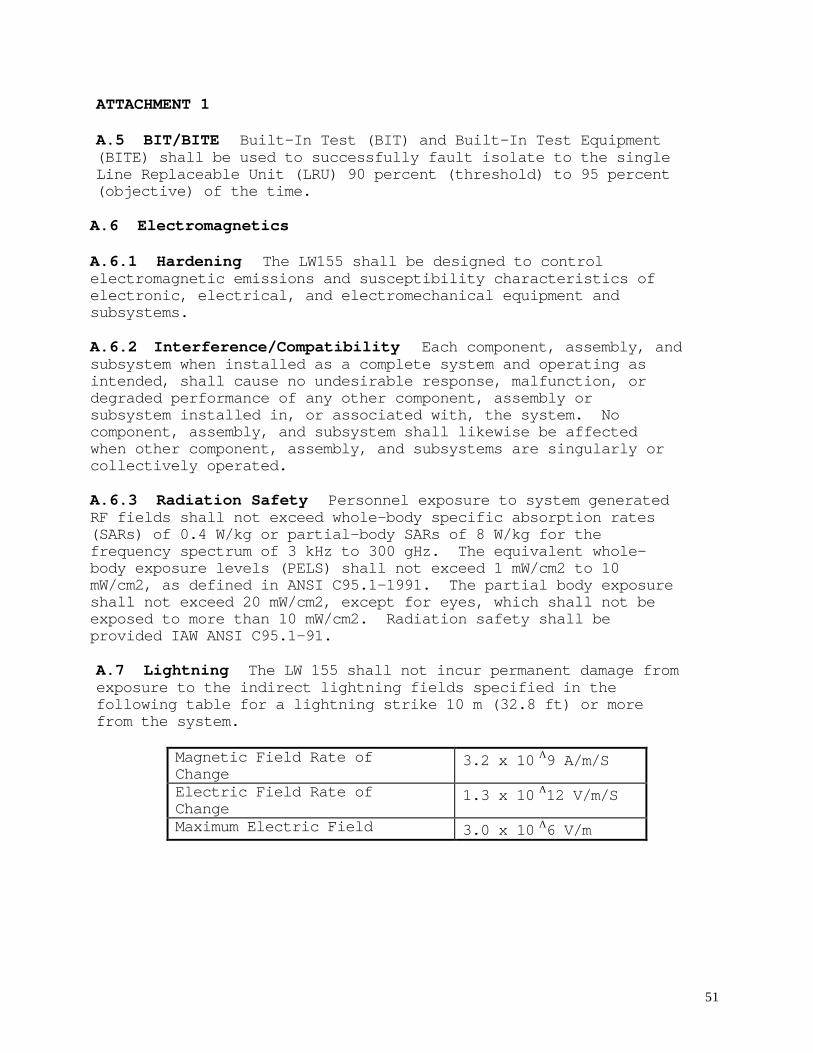
A.7 Lightning The LW 155 shall not incur permanent damage fromexposure to the indirect lightning fields specified in thefollowing table for a lightning strike 10 m (32.8 ft) or morefrom the system.
Magnetic Field Rate ofChange
3.2 x 10 Λ9 A/m/S
Electric Field Rate ofChange
1.3 x 10 Λ12 V/m/S
Maximum Electric Field 3.0 x 10 Λ6 V/m

52