lightweighting the can pack - wrap
TRANSCRIPT
Final Report
Lightweighting the can pack
A technical review and recommendations for the can package: performance requirements and lightweighting.
Project code: RSI001 Research date: April 2007-May2008 Date: September 2008
WRAP helps individuals, businesses and local authorities to reduce waste and recycle more, making better use of resources and helping to tackle climate change.
Written by: Christine Watson, Supplier QESH Manager
Front cover photography: Examples of cans WRAP and Coca-Cola Enterprises Ltd believe the content of this report to be correct as at the date of writing. However, factors such as prices, levels of recycled content and regulatory requirements are subject to change and users of the report should check with their suppliers to confirm the current situation. In addition, care should be taken in using any of the cost information provided as it is based upon numerous project-specific assumptions (such as scale, location, tender context, etc.). The report does not claim to be exhaustive, nor does it claim to cover all relevant products and specifications available on the market. While steps have been taken to ensure accuracy, WRAP cannot accept responsibility or be held liable to any person for any loss or damage arising out of or in connection with this information being inaccurate, incomplete or misleading. It is the responsibility of the potential user of a material or product to consult with the supplier or manufacturer and ascertain whether a particular product will satisfy their specific requirements. The listing or featuring of a particular product or company does not constitute an endorsement by WRAP and WRAP cannot guarantee the performance of individual products or materials. This material is copyrighted. It may be reproduced free of charge subject to the material being accurate and not used in a misleading context. The source of the material must be identified and the copyright status acknowledged. This material must not be used to endorse or used to suggest WRAP’s endorsement of a commercial product or service. For more detail, please refer to WRAP’s Terms & Conditions on its web site: www.wrap.org.uk
Lightweighting the can pack 1
Executive summary This project has successfully demonstrated that the current beverages aluminium can pack has the potential to be lightweighted further than the industry initially thought possible, not only by reducing the gauge of the can and end but by modifying the design of the can package. The partnership with WRAP enabled the can makers in Europe (a non-profit organisation - Beverage Can Makers Europe (BCME)) to conduct rigorous, external testing on behalf of all customers of the can pack – for carbonated soft drinks and beer1. The external testing was completed using a highly respected industry laboratory, which set up real life challenges for the can. Extreme conditions were created and “performance” measured. Coca-Cola Enterprises Inc.2, as the lead project partner, has clear guidelines around lightweighting, the aim was always to achieve the same or better performance from a lightweight can pack. However, with this project, the team took a different approach and tested the boundaries of what the requirements actually needed to be. This project was about finding real market requirements and building a can with those requirements in mind. The project team, with members from Coca-Cola Enterprises Inc., the BCME, The Coca-Cola Company and WRAP, set out to truly lightweight the can pack by determining the performance challenges of the can pack and then evaluating the components of the specification which would meet those challenges. The relationship between dimension and performance was established, and a “calculator” to aid in future lightweighting opportunities developed. The project team’s aim was to not only lightweight the can, but to also link the performance requirements to a dimensional specification which would allow the beverage can industry to maintain flexibility. The can pack needed to work well on existing filling lines for the entire beverage can industry. It was recognised that changing the beverage can industry would not be easy, but the team’s aim was “a seamless transition” to the new lightweight can. Therefore, for the purposes of testing the new can pack, filling and seaming processes at CCE needed to be maintained and as much “noise” from the seaming process removed, but nothing significantly altered. Trials needed to happen without significant modifications, and the results would give the project team significant insight for the rest of the beverage can industry. The result of the project indicated that there was no difference filling and processing the lightweight can. As a direct result of the WRAP support, the BCME initiated external studies to find the actual performance requirements for the beverage can pack. These studies would take a year to complete, so in the interim, the project team targeted an acceptable midwall reduction for the trial period. During the trials, the performance specification remained unchanged, only the dimensions changed. Internal testing showed that even with the dimensional changes, the can pack still met current performance specifications. The reduced midwall can was trialled through various stages of the supply chain, to assess:
the capability of the can making process;
transporting and storage of empty cans, palletised and triple stacked;
filling line and the seaming processes;
testing extreme environmental conditions and the effect on the package;
trialling the portfolio of CCE’s vending machines; and
customer and consumer feedback.
Several trials were designed to test the reduced midwall both at the can plant and on the CCE filling lines. Critical parameters were thoroughly tested in real life scenarios, and the results were positive.
1 The “beverage industry”, as used within this document, implies both the carbonated soft drinks and beer industries.
2 Throughout this document The Coca-Cola Company may be referred to as TCCC. The bottler, and the lead project partner, is Coca-Cola Enterprises Inc., and is referred to as CCE.
Lightweighting the can pack 2
The external testing was commissioned by the BCME, with support from WRAP, and completed during the trial period of the reduced midwall. The external testing validated the results that the project team experienced during the filling trials. The 3 main features of the external testing were:
Axial load testing of the empty and filled can (axial load is the vertical force the can pack may experience in
its life cycle, a crushing force).
Understand the relationship between internal pressure of the can pack (bar) and the axial load failure
(Newtons) and develop an equation for future lightweighting.
Testing the internal pressure of the can pack in extreme environment scenarios.
Axial load – Phase 1: The axial load is important to the can design in terms of moving a can pack through manufacturing, warehousing and distribution. The greatest forces will be at the bottom of the pallet, and more so at the bottom of a triple stacked pallet. PIRA carried out the tests, which consisted of measuring the force on every can position on the lower layer of a pallet and simulating triple stacking and distribution. The test cans were fitted with devices, called “load cells” (which will be detailed later in the report), which measured the forces during the simulation as “axial load”. Axial load – Phase 2: In phase 2 of the PIRA tests, the filled can pack was also evaluated in terms of internal pressure and the axial load. Understanding the relationship (which is similar for both steel and aluminium can packs), enabled PIRA to determine a “calculator” for future lightweighting, including 250ml, 330ml and 500ml cans sizes. The variables to input into the equation are:
Empty can top load strength for “new” specification can.
Design top load for individual filled seamed pressurised can (defined in Phase 1).
Internal pressure (bar).
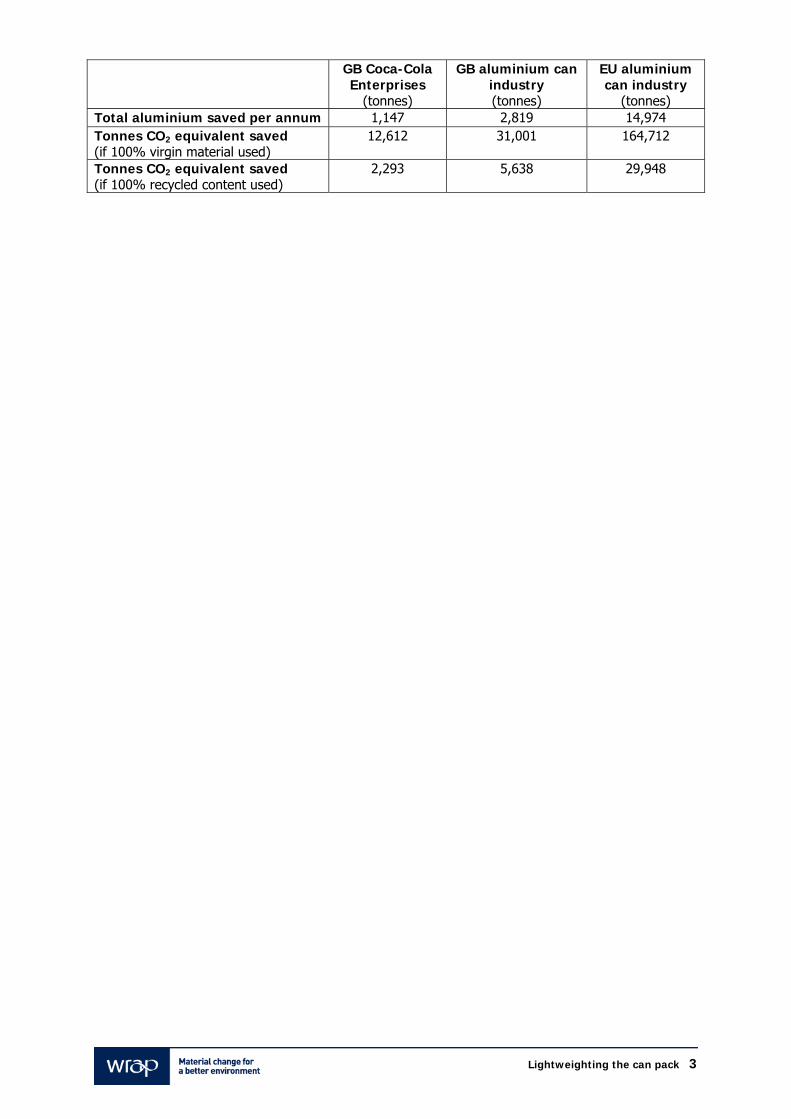
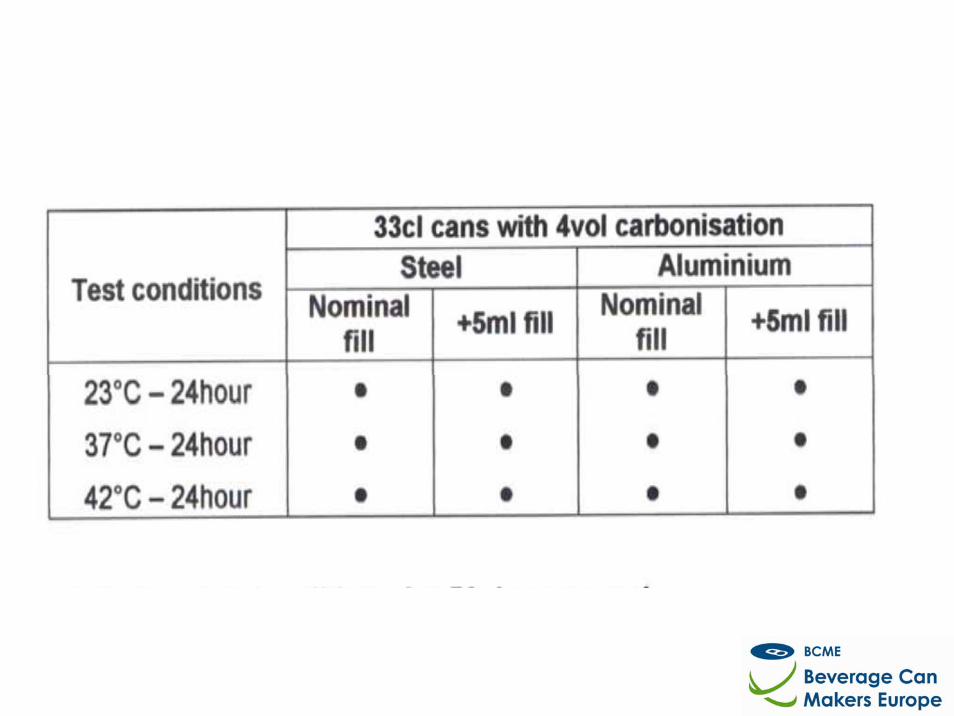
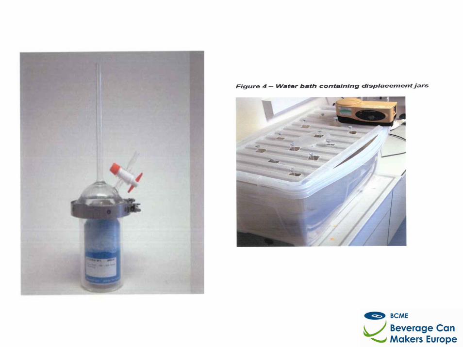
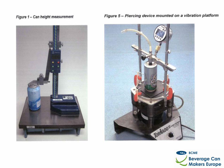
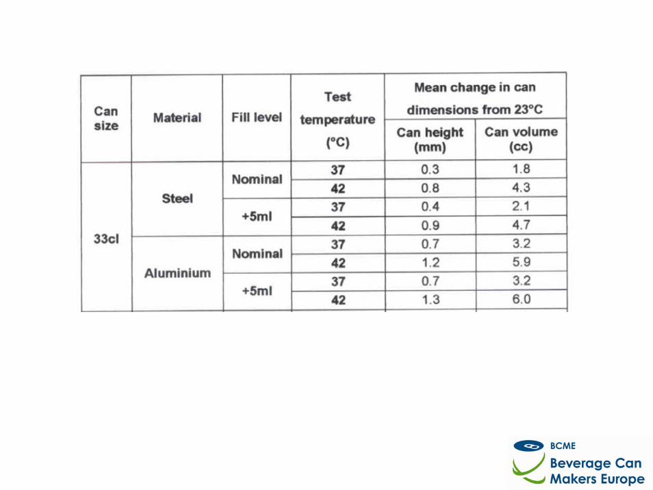
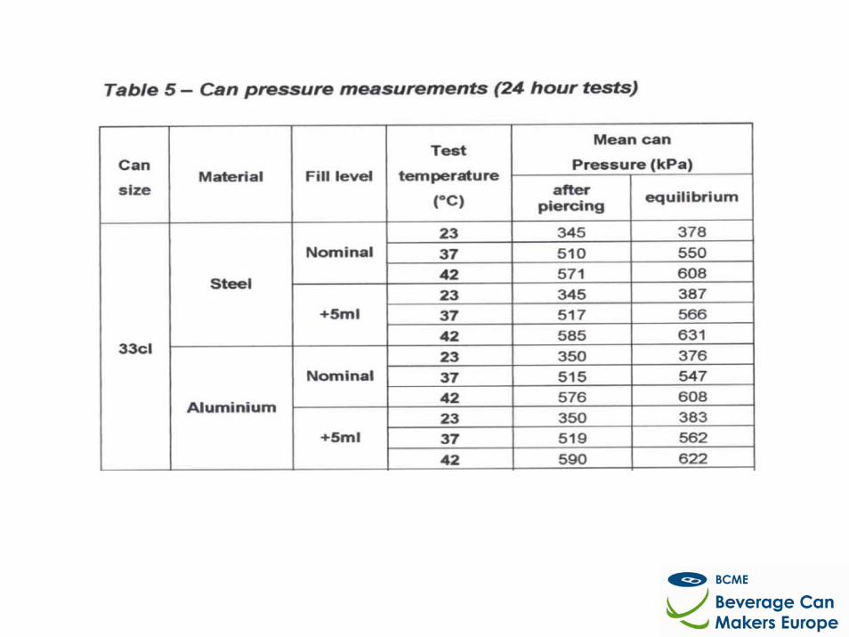
Extreme pressure evaluation: The test packs were made into a sealed containers and apparatus designed to evaluate the can and end as a closed system. The can and end was viewed in terms of “a packaging system”. The can was sealed with known volumes and known carbonation were then exposed to extreme temperatures and time. The results showed that the internal pressure requirements for the can pack were lower than the current specification at elevated temperatures. However, the study confirmed that at very extreme temperatures and time (42ºC and 24 hours) the packaging system “met current performance specifications”. However, the extreme temperature and time was not indicative of a real life scenario, and the aim was to test the boundary. In addition, can “growth”, due to the increased temperature and pressure, was also measured and the failure mode (at extreme temperatures) was predominantly a seam break, not typically a can or can end specific catastrophic failure, and not attributed to lightweighting. As a result of the findings from the BCME studies, which were funded by WRAP, the midwall specification for the can was changed and internal pressure limits for the end reduced. The studies also provided the technical community clear success criteria for the continuation of lightweighting the can pack without risking the quality of the package. Funding from WRAP was critical, namely for the cost of the Axial load validation, Phase 1 and 2, as well as, the internal pressure, extreme environmental testing, encompassing the beverage industry. The work done by the external research facility, PIRA, was the foundation in understanding the true performance requirements of the can package. The tests also indicated that further lightweighting is possible, given the capability improvements at the can maker. The relationship between internal pressures and axial load failure is known, and a “lightweight calculator” was developed as an aid to further lightweighting. The affect of the can in an extreme environment is now understood and the information, again, will greatly help further lightweighting endeavours. As a result of the lightweighting during the trial period, the following weight savings can be calculated on a per annum basis. The figures include aluminium can bodies and ends – material weight reduction.
Lightweighting the can pack 4
Contents 1.0 Introduction to can lightweighting.......................................................................................... 5
1.1 Background...........................................................................................................................5 1.2 Performance evaluation .........................................................................................................6
2.0 Axial Load: Establishing the Relationship Between Performance and Dimension.................. 7 2.1 Axial Load Evaluation.............................................................................................................7 2.2 Research Methodology and Results.........................................................................................8 2.3 Line Trials – T1 (Level 1 Trials) ............................................................................................10 2.4 Line Trials – T2 (Level 2 Trials) ............................................................................................11
2.4.1 How Much Does Midwall Thickness Affect the Filling Line Performance? .....................12 2.5 Body Maker Capability..........................................................................................................12
3.0 Internal Lacquer Evaluation: Validation of Potential Savings .............................................. 13 3.1 Internal Lacquer and Optimum Lacquer Weight.....................................................................13
4.0 Thermal Can Test: Establishing the Relationship Between Performance and the Extreme Environment............................................................................................................................ 14 4.1 Extreme Environmental Evaluation........................................................................................14
5.0 Project Conclusion: A Positive Step to Further Lightweight the Can Pack ........................... 15 5.1 Estimated per Annum Weight Reduction ...............................................................................15
Appendix 1: Axial Load Reports ......................................................................................................... 16 Appendix 1.1: BCME (PIRA study) ..................................................................................................... 16 Appendix 1.2 Rexam Axial Load versus midwall thickness................................................................ 34 Appendix 2: Capability studies........................................................................................................... 50 Appendix 2.1: Per body maker- Midwall capability studies template................................................ 50 Appendix 2.2: Capability study at Wakefield ..................................................................................... 51 Appendix 3: Vending Trial .................................................................................................................. 61 Appendix 3.1: Vending Trial Capability study at Wakefield ............................................................... 61 Appendix 4: Internal lacquer ............................................................................................................. 63 Appendix 4.1: Internal lacquer study ................................................................................................ 63 Appendix 5: Extreme Environment Can Test...................................................................................... 87 Appendix 5.1: Environmental Investigation ..................................................................................... 87
Lightweighting the can pack 5
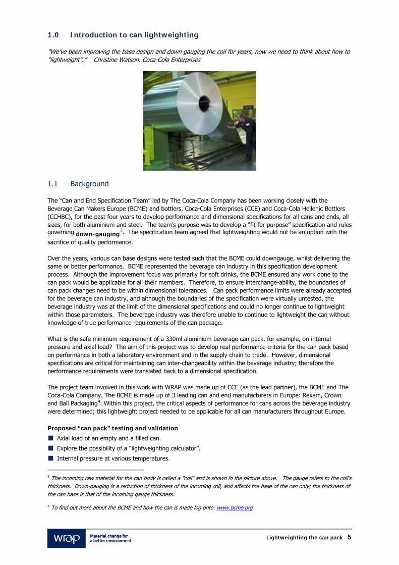
1.0 Introduction to can lightweighting “We’ve been improving the base design and down gauging the coil for years, now we need to think about how to “lightweight”.” Christine Watson, Coca-Cola Enterprises
1.1 Background The “Can and End Specification Team” led by The Coca-Cola Company has been working closely with the Beverage Can Makers Europe (BCME) and bottlers, Coca-Cola Enterprises (CCE) and Coca-Cola Hellenic Bottlers (CCHBC), for the past four years to develop performance and dimensional specifications for all cans and ends, all sizes, for both aluminium and steel. The team’s purpose was to develop a “fit for purpose” specification and rules governing down-gauging
3. The specification team agreed that lightweighting would not be an option with the
sacrifice of quality performance. Over the years, various can base designs were tested such that the BCME could downgauge, whilst delivering the same or better performance. BCME represented the beverage can industry in this specification development process. Although the improvement focus was primarily for soft drinks, the BCME ensured any work done to the can pack would be applicable for all their members. Therefore, to ensure interchange-ability, the boundaries of can pack changes need to be within dimensional tolerances. Can pack performance limits were already accepted for the beverage can industry, and although the boundaries of the specification were virtually untested, the beverage industry was at the limit of the dimensional specifications and could no longer continue to lightweight within those parameters. The beverage industry was therefore unable to continue to lightweight the can without knowledge of true performance requirements of the can package. What is the safe minimum requirement of a 330ml aluminium beverage can pack, for example, on internal pressure and axial load? The aim of this project was to develop real performance criteria for the can pack based on performance in both a laboratory environment and in the supply chain to trade. However, dimensional specifications are critical for maintaining can inter-changeability within the beverage industry; therefore the performance requirements were translated back to a dimensional specification. The project team involved in this work with WRAP was made up of CCE (as the lead partner), the BCME and The Coca-Cola Company. The BCME is made up of 3 leading can and end manufacturers in Europe: Rexam, Crown and Ball Packaging4. Within this project, the critical aspects of performance for cans across the beverage industry were determined; this lightweight project needed to be applicable for all can manufacturers throughout Europe. Proposed “can pack” testing and validation
Axial load of an empty and a filled can.
Explore the possibility of a “lightweighting calculator”.
Internal pressure at various temperatures.
3 The incoming raw material for the can body is called a “coil” and is shown in the picture above. The gauge refers to the coil’s thickness. Down-gauging is a reduction of thickness of the incoming coil, and affects the base of the can only; the thickness of the can base is that of the incoming gauge thickness. 4 To find out more about the BCME and how the can is made log onto: www.bcme.org
Lightweighting the can pack 6
Burst testing, and failure mode evaluation.
Capability template, per body maker.
Distribution and vending capability.
Customer and consumer - trade evaluation.
Line performance (CCE at Wakefield, Milton Keynes and Sidcup facilities).
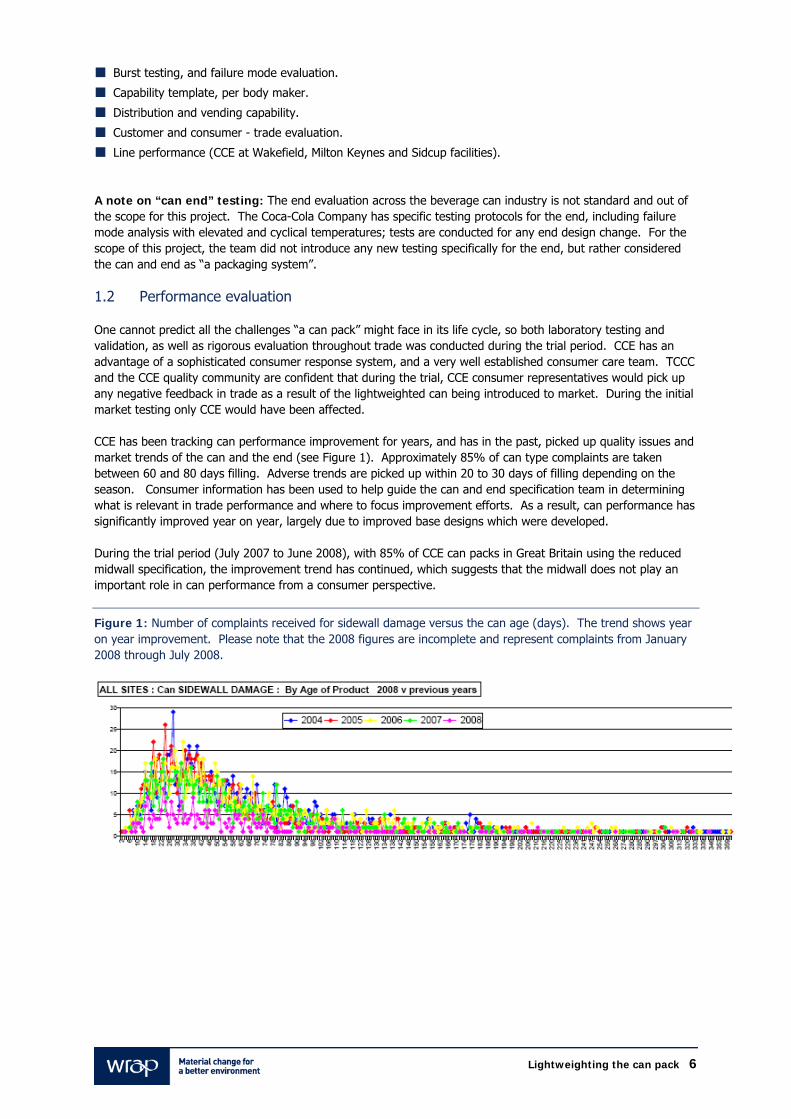
A note on “can end” testing: The end evaluation across the beverage can industry is not standard and out of the scope for this project. The Coca-Cola Company has specific testing protocols for the end, including failure mode analysis with elevated and cyclical temperatures; tests are conducted for any end design change. For the scope of this project, the team did not introduce any new testing specifically for the end, but rather considered the can and end as “a packaging system”. 1.2 Performance evaluation One cannot predict all the challenges “a can pack” might face in its life cycle, so both laboratory testing and validation, as well as rigorous evaluation throughout trade was conducted during the trial period. CCE has an advantage of a sophisticated consumer response system, and a very well established consumer care team. TCCC and the CCE quality community are confident that during the trial, CCE consumer representatives would pick up any negative feedback in trade as a result of the lightweighted can being introduced to market. During the initial market testing only CCE would have been affected. CCE has been tracking can performance improvement for years, and has in the past, picked up quality issues and market trends of the can and the end (see Figure 1). Approximately 85% of can type complaints are taken between 60 and 80 days filling. Adverse trends are picked up within 20 to 30 days of filling depending on the season. Consumer information has been used to help guide the can and end specification team in determining what is relevant in trade performance and where to focus improvement efforts. As a result, can performance has significantly improved year on year, largely due to improved base designs which were developed. During the trial period (July 2007 to June 2008), with 85% of CCE can packs in Great Britain using the reduced midwall specification, the improvement trend has continued, which suggests that the midwall does not play an important role in can performance from a consumer perspective.
Figure 1: Number of complaints received for sidewall damage versus the can age (days). The trend shows year on year improvement. Please note that the 2008 figures are incomplete and represent complaints from January 2008 through July 2008.
Lightweighting the can pack 7
2.0 Axial Load: Establishing the Relationship Between Performance and Dimension
2.1 Axial Load Evaluation Axial load5 of a filled can is a critical parameter for performance specifications. The canning industry views the axial load as a measure of how much of a load the can will withstand, standing vertically. Although there is a specification for axial load of 800 Newtons minimum, the boundaries have not been tested. The can industry, until now, did not understand the actual load requirements of a filled can, for example what a can experiences at the bottom of a pallet, and at the bottom of a triple stacked pallet. Two axial load evaluations were initiated to help better understand the axial load at any given time and to provide a predictor for future lightweighting opportunities. The first study evaluated the axial load requirements of a filled can through a lifecycle scenario. The study, completed by PIRA, included 250ml, 330ml and 500ml aluminium and steel can packs, for both beer and carbonated soft drinks. The study shows the axial load requirements of a filled can, palletised and triple stacked. The PIRA study was split into 2 phases:
PIRA Phase 1 – Design “load cells” to determine the axial load requirements for filled beverage cans (from
the point of palletisation to the point of use by the consumer).
PIRA Phase 2 - establish the relationship between empty can axial load performance and filled can axial
crush performance through evaluation of a range of factors that influence filled can top load strength (internal
pressure and empty can specification). The benefit of the PIRA Phase 2 evaluation is the possibility of
developing a “calculator” to base future lightweighting opportunities.
The PIRA studies (including the internal pressure analysis to be discussed later) would take a year to complete, so in the mean time, using interim reports, the project team targeted a midwall reduction for the trial period. During the trials, the performance specification remained unchanged, only the midwall dimension changed. Internal testing showed that even with midwall reduction, the can pack still met current performance specifications.
Rexam’s axial load study (internal study) – in order to find a midwall target for the duration of the trial,
Rexam’s axial load study measured the axial load whilst varying the can’s midwall thickness. The trial cans
were produced in Rexam’s Research Centre using the current can design, and changing the midwall thickness
at intervals of 0.001mm. With this information, it was possible to predict the axial strength of a can with a
particular midwall thickness. With Rexam’s information the team was able to provide a safe midwall
dimension for the trial cans.
The PIRA studies and Rexam midwall evaluation are attached in Appendix 1. Results of these studies are outlined below.
5 The engineering description of axial load is “a load applied along or parallel to and concentric with the primary axis”. Axial load is critical parameter in the can specification, and it represents the can pack’s ability to withstand crushing, smashing and distorting under vertical loads. Axial load has been a part of the Coca-Cola specification for many years, but the value in the specification is a historical number. To find the axial load is a simple test to do: it’s the load it takes to crush the empty can. What is unknown is the vertical load that a can pack must withstand, in trade, such as, at the bottom of a pallet.
Lightweighting the can pack 8
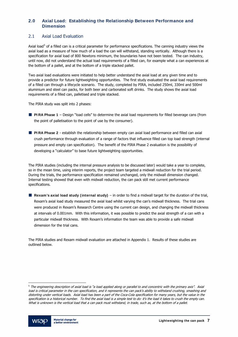
2.2 Research Methodology and Results PIRA Phase 1: Load cells (pictured below in Figure 2) were designed for the purpose of measuring the axial load for the various can designs (250ml, 330ml and 500ml) and were placed at the bottom of a triple stacked pallet, at every can position. The higher loads were predominantly found at the edges of the pallet, under the pallet “bearer blocks” (the support structure of the pallet). The detailed results are documented in Appendix 1.
Figure 2: Photograph of the load cells designed to mimic the can pack, for the purpose of measuring the load at various places within the pallet (Newtons).
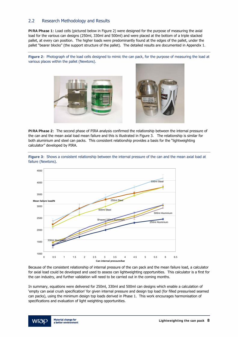
PIRA Phase 2: The second phase of PIRA analysis confirmed the relationship between the internal pressure of the can and the mean axial load mean failure and this is illustrated in Figure 3. The relationship is similar for both aluminium and steel can packs. This consistent relationship provides a basis for the “lightweighting calculator” developed by PIRA.
Figure 3: Shows a consistent relationship between the internal pressure of the can and the mean axial load at failure (Newtons). Because of the consistent relationship of internal pressure of the can pack and the mean failure load, a calculator for axial load could be developed and used to assess can lightweighting opportunities. This calculator is a first for the can industry, and further validation will need to be carried out in the coming months. In summary, equations were delivered for 250ml, 330ml and 500ml can designs which enable a calculation of ‘empty can axial crush specification’ for given internal pressure and design top load (for filled pressurised seamed can packs), using the minimum design top loads derived in Phase 1. This work encourages harmonisation of specifications and evaluation of light weighting opportunities.
250ml Aluminium
250ml Steel
330ml Aluminium
330ml Steel
500ml Aluminium 500ml Steel
Shaped 330ml Aluminium
1000
1500
2000
2500
3000
3500
4000
4500
0 0.5 1 1.5 2 2.5 3 3.5 4 4.5 5 5.5 6 6.5 Can internal pressure/bar
Mean failure load/N
Lightweighting the can pack 9
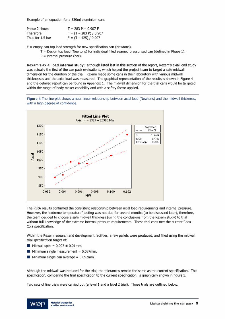
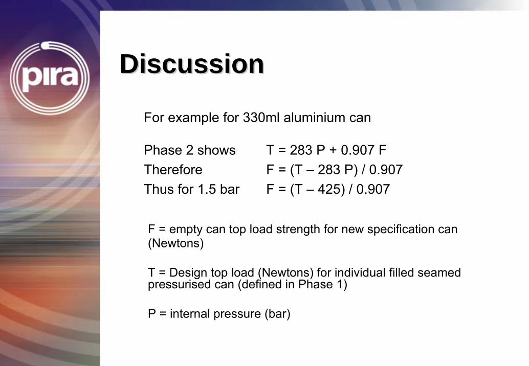
Example of an equation for a 330ml aluminium can: Phase 2 shows T = 283 P + 0.907 F Therefore F = (T – 283 P) / 0.907 Thus for 1.5 bar F = (T – 425) / 0.907 F = empty can top load strength for new specification can (Newtons). T = Design top load (Newtons) for individual filled seamed pressurised can (defined in Phase 1). P = internal pressure (bar). Rexam’s axial load internal study: although listed last in this section of the report, Rexam’s axial load study was actually the first of the can pack evaluations, which helped the project team to target a safe midwall dimension for the duration of the trial. Rexam made some cans in their laboratory with various midwall thicknesses and the axial load was measured. The graphical representation of the results is shown in Figure 4 and the detailed report can be found in Appendix 1. The midwall dimension for the trial cans would be targeted within the range of body maker capability and with a safety factor applied.
Figure 4 The line plot shows a near linear relationship between axial load (Newtons) and the midwall thickness, with a high degree of confidence.
The PIRA results confirmed the consistent relationship between axial load requirements and internal pressure. However, the “extreme temperature” testing was not due for several months (to be discussed later), therefore, the team decided to choose a safe midwall thickness (using the conclusions from the Rexam study) to trial without full knowledge of the extreme internal pressure requirements. These trial cans met the current Coca-Cola specification. Within the Rexam research and development facilities, a few pallets were produced, and filled using the midwall trial specification target of:
Midwall spec = 0.097 ± 0.01mm.
Minimum single measurement = 0.087mm.
Minimum single can average = 0.092mm.
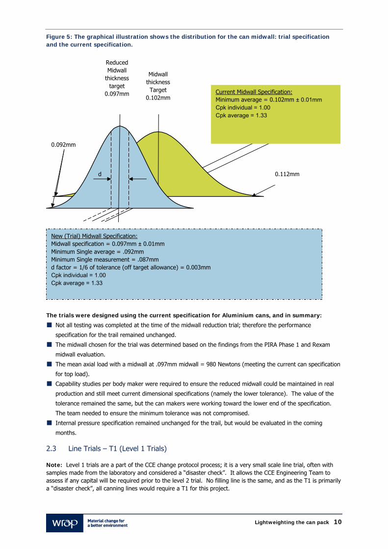
Although the midwall was reduced for the trial, the tolerances remain the same as the current specification. The specification, comparing the trial specification to the current specification, is graphically shown in figure 5. Two sets of line trials were carried out (a level 1 and a level 2 trial). These trials are outlined below.
Lightweighting the can pack 10
Figure 5: The graphical illustration shows the distribution for the can midwall: trial specification and the current specification.
The trials were designed using the current specification for Aluminium cans, and in summary:
Not all testing was completed at the time of the midwall reduction trial; therefore the performance
specification for the trail remained unchanged.
The midwall chosen for the trial was determined based on the findings from the PIRA Phase 1 and Rexam
midwall evaluation.
The mean axial load with a midwall at .097mm midwall = 980 Newtons (meeting the current can specification
for top load).
Capability studies per body maker were required to ensure the reduced midwall could be maintained in real
production and still meet current dimensional specifications (namely the lower tolerance). The value of the
tolerance remained the same, but the can makers were working toward the lower end of the specification.
The team needed to ensure the minimum tolerance was not compromised.
Internal pressure specification remained unchanged for the trail, but would be evaluated in the coming
months.
2.3 Line Trials – T1 (Level 1 Trials) Note: Level 1 trials are a part of the CCE change protocol process; it is a very small scale line trial, often with samples made from the laboratory and considered a “disaster check”. It allows the CCE Engineering Team to assess if any capital will be required prior to the level 2 trial. No filling line is the same, and as the T1 is primarily a “disaster check”, all canning lines would require a T1 for this project.
Midwall thickness Target
0.102mm
Reduced Midwall
thickness target
0.097mm
0.112mm d
Current Midwall Specification: Minimum average = 0.102mm ± 0.01mm Cpk individual = 1.00 Cpk average = 1.33
0.092mm
New (Trial) Midwall Specification: Midwall specification = 0.097mm ± 0.01mm Minimum Single average = .092mm Minimum Single measurement = .087mm d factor = 1/6 of tolerance (off target allowance) = 0.003mm Cpk individual = 1.00 Cpk average = 1.33
Lightweighting the can pack 11
The cans, with the midwall trial specification outlined above, were evaluated in the level 1 trials on CCE’s filling lines at Wakefield and Milton Keynes. The aim of this T1 was to better understand can damage, sealing, fill volume, empty and filled pallet stability and provide samples for a vending trial. Prior to the T1 evaluation, line audits were conducted by CCE and Rexam personnel. The purpose of the line audit was to highlight any potential issues and/or filling situations which needed to be closely observed during the actual T1 evaluation. These audits include the marking up of several areas of the line, for observation, and in general how the cans behave at various “pinch points” on the filling line. The audit and the subsequent can comparison is done by observation. Trial cans were seamed with the current specification end, as well as a reduced gauge end (from 0.220mm to 0.215mm gauge); there were no changes to the seamers or seams, and no issues were identified. However, on the Milton Keynes line, specific issues were identified in the seaming process on the reduced gauge end (0.215mm). The problem persisted on both the current and the reduced midwall can, therefore small seamer upgrades were necessary at Milton Keynes to continue trials on reduced gauge ends, namely modifications to the conveying of the ends into the seamer. The canning line at Wakefield did not require these modifications. In conclusion, the reduced midwall had no detrimental effect to the can pack during filling (at Wakefield and Milton Keynes sites). When making any design change within CCE, change control protocols require a “vending trail”. Vending trials were completed using the CCE portfolio of vending equipment and a lightly sparkling product. The tests were successful. The vending report can be found in Appendix 3. 2.4 Line Trials – T2 (Level 2 Trials) Note: Level 2 trials are part of the CCE change protocol process; it’s a small scale line trial which tries to mimic a steady state environment. Often the trial production is made in a factory, not a laboratory. During the T2 line trials, CCE operations personnel are able to make an assessment of the package on the filling line and make recommendations if required. As T2 is primarily a line assessment, for this project, each CCE canning line needed a T2. Level 2 trials were scheduled at CCE Wakefield using Rexam cans (from the Rexam Wakefield plant). Level 2 trials required a significant tooling change at the can maker, and considerable downtime was needed to make the tooling changes. Due to the high demand for cans during 2007 summer, not all of the body makers could be converted to the reduced midwall specification (the change over would take 2 days and CCE had the risk that the midwall reduction might not work). Instead, a third of the body makers were retooled with the midwall reduction. The aim was to build a small volume of reduced midwall cans, enough to run a line for thirty minutes at full speed, steady state. Then, if all went to plan, incrementally convert all can body makers to the reduced midwall at Rexam Wakefield. The palletised cans produced in the T2 were examined for creases, dents and can damage. These test pallets were compared with normal production cans (which were produced moments before the T2), as an observation check to ensure the midwall did not increase can damage. There was no difference in can damage comparing the current to the reduced midwall can. A small number of dents at the base were observed, but this had nothing to do with the midwall reduction and is quite common in can filling. Some very small evidence of creasing was apparent, but still there was no difference when compared to the control cans. Can creasing is also very common and is mostly related to seamer set-up. As a result, small seamer modifications were needed to reduce the level of can creases, again, not at all related to midwall reduction, but rather identified only because of close inspection of the current can. The Wakefield trial took place in mid July 2007, and Rexam began to incrementally convert to the new midwall specification. The criterion for conversion to the new midwall was a “capable body maker”. A capability study is the statistical tool to assess whether or not a machine is capable of consistently producing “in specification” material. Each body maker was assessed and not all were deemed capable. The body makers which were not capable required a routine overhaul (body makers, as with any complex machinery require periodic and detailed maintenance, also known as an “overhaul”). Approximately 85% of the cans from Rexam Wakefield were converted to the reduced midwall and 15% remained on the old specification. By November 2007, all can body makers at Wakefield were converted to the new specification.
Lightweighting the can pack 12
Between July and November 2007, the T1 and T2 trials were completed at the Milton Keynes and Sidcup sites using production cans from Rexam Wakefield. Similar to the Wakefield trial, the other filling lines did not create more can damage when compared to the original 0.102mm midwall. By March 2008, all 330ml cans produced at Rexam Milton Keynes were converted to the new midwall specification. All cans produced now from Rexam Wakefield and Milton Keynes plants are in trade and include Coca-Cola’s entire brand portfolio available in can packs (Coca-Cola regular and diet, Cherry Coke, Sprite, Fanta, Dr. Pepper and Lilt). Since July 2007, no negative feedback on can damage has been reported from the marketplace. No filling line issues were observed at the CCE filling sites, Wakefield or Milton Keynes. As an extra validation, Rexam sampled production cans (natural production population) with the reduced midwall at 0.097mm. They carried out axial load tests on the cans (similar to Figure 3). Rexam sampled 24 cans from each 0.097mm can body maker, measured the midwall and recorded the axial load. No anomalies were detected and results were in line with laboratory testing. 2.4.1 How Much Does Midwall Thickness Affect the Filling Line Performance? The Wakefield line fills at approximately 2,000 cans per minute. The line is fairly old, however, no major engineering modifications to the filling operations were needed to move to the new midwall specifications. Also, it was interesting to note that during conversion, filling was taking place with some body makers on the new specification and some on the old (or a mixture of 85% new and 15% old midwall thickness). Following the trial, 15% of the body makers remained on the 0.102mm midwall target due to body maker capability issues (as mentioned earlier). The differences in midwall thickness (0.97 and 0.102mm) did not seem to have significant impact on the filling process. In essence, the Wakefield filling line did not recognise the difference between the two midwall thicknesses, even when running mixed together at the same time. Similarly at Milton Keynes, also on 85% reduced midwall and 15% at 0.102mm, the difference in midwall had no effect on filling line performance. In summary, a complete industry conversion is highly likely, and filling lines would “not notice” the difference between the 0.102 and .097mm midwall. However, since the T2 trials were undertaken, outlined above, some further issues have been observed on the Sidcup filling line. For example, the burst rate for cans is generally higher than the norm. However, this is not considered to be a result of the lightweighted can, but more down to a fault in the conveying system, and an alignment problem at the filler. As a result, modifications to the seamer are needed but are not related to the midwall reduction. CCE has decided to wait until after 2008 summer peak period to make any modifications to the canning line and to interrupt supply at the can maker’s facility. The volume of cans through Sidcup have a reduced coil gauge, resulting in a thinner can base, which was implemented in March 2008, but the midwall has not yet been reduced. The reduced midwall will be planned in after the summer peak period. 2.5 Body Maker Capability In order to ascertain the minimum specification for midwall can thickness, each can body maker would need to be evaluated separately to understand the natural variation per machine. For successful can lightweighting to take place, it is recommended that:
The can body maker has an “online monitoring” system for can thickness and the dimensional trends can be
identified per body maker and addressed immediately;
Each body maker should have a capability study done prior to midwall reduction to ensure that it is capable of
achieving the lower dimensional tolerance; and
Due to various maintenance regimes per can maker plant, the body makers tooling wear should be well
documented in terms of changes to critical dimensions over time before lightweighting opportunities are
initiative.
Capability studies undertaken for Rexam are attached in Appendix 2.
Lightweighting the can pack 13
3.0 Internal Lacquer Evaluation: Validation of Potential Savings 3.1 Internal Lacquer and Optimum Lacquer Weight The objective of the “Internal Lacquer” study was to validate the specification for internal lacquer weight6. The purpose of this study was to find out the minimum lacquer weight whilst maintaining good performance and good internal can coverage. Internal lacquer is important in the production of aluminium and steel cans, and plays a critical role in isolating the product from the metal which may cause off-taste and leaking problems after filling. The function of the internal lacquer is to cover the base metal; the lacquer acts as a barrier between the base metal and the liquid. The can industry has a standard process for measuring lacquer coverage – this is called an enamel rating. Enamel rating involves testing a production can by filling the can with a fluid electrolyte, then charging the can with a current and measuring the current in milliamps. There should be minimal electrical current within the can when the base metal has a good lacquer barrier. This study involved varying the internal lacquer weight, using various Coca-Cola products (regular Coca-Cola and Sprite were used in test samples, but any product could have been used to make this assessment), and measuring the enamel rating. The results showed that a reduction of the lacquer weight caused an increased electrical current in a charged can. Therefore, the internal lacquer weight specification is already at optimum, and current practices are not conducive to a reduction in inner lacquer thickness. The report is attached in appendix 4.
6 Internal lacquer is a part of the can design, similar to the print on the outside of the can, a protective barrier is sprayed into the can. The can industry measures the amount of lacquer sprayed into the can as a weight and also as a correct distribution around the inside of the can, covering all areas where the product comes in contact with the metal.
Lightweighting the can pack 14
4.0 Thermal Can Test: Establishing the Relationship Between Performance and the Extreme Environment
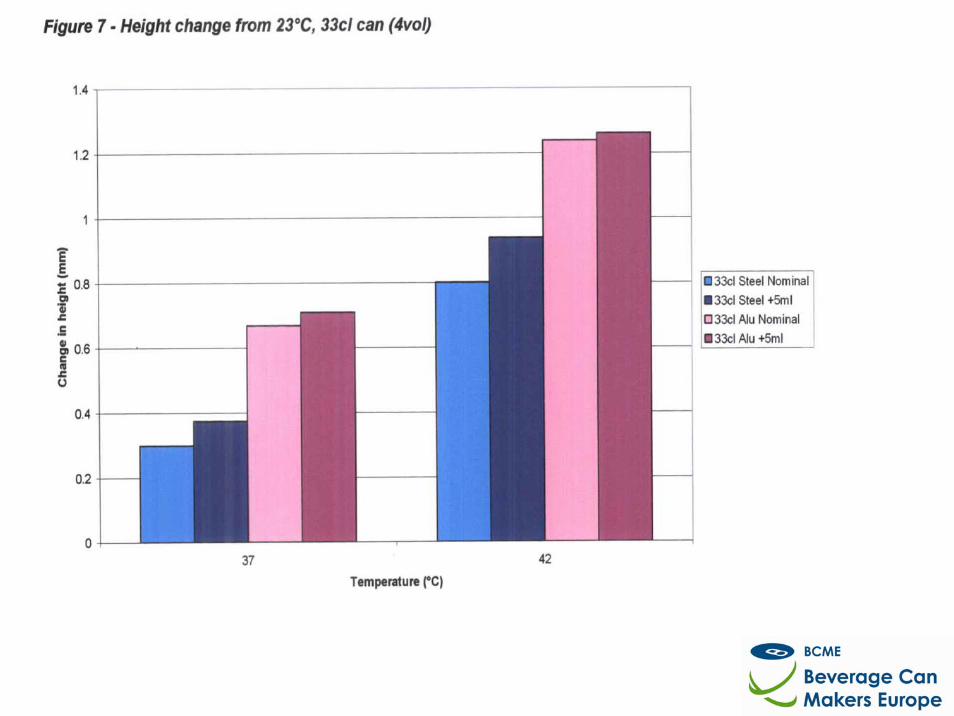
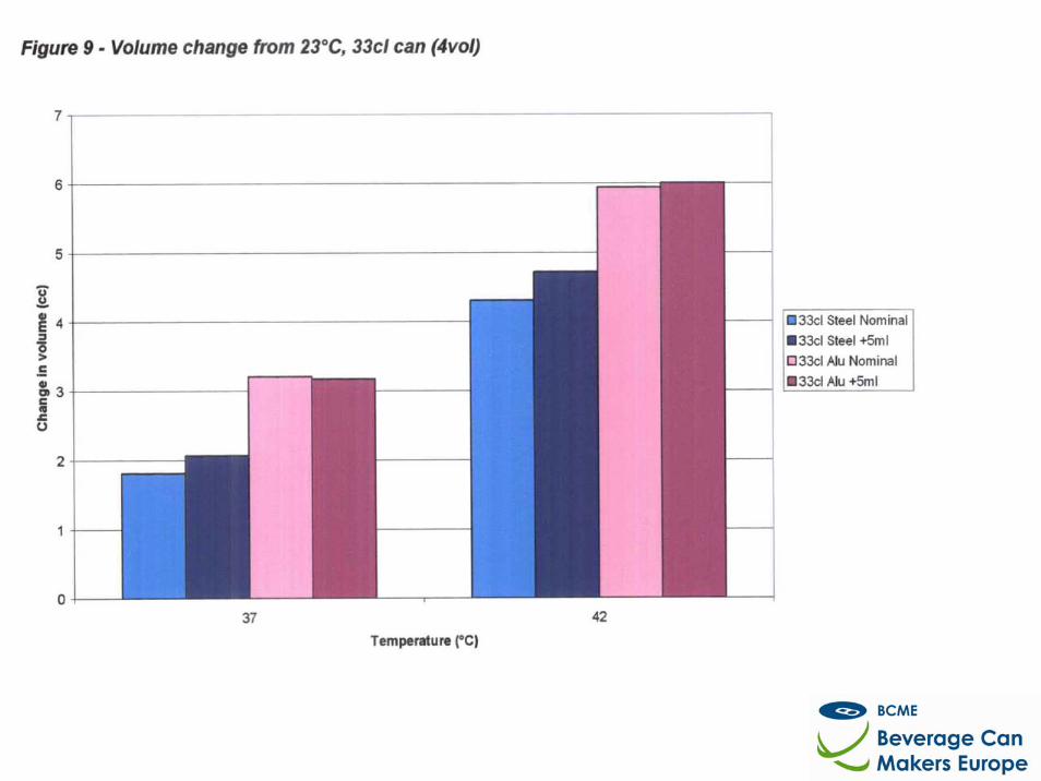
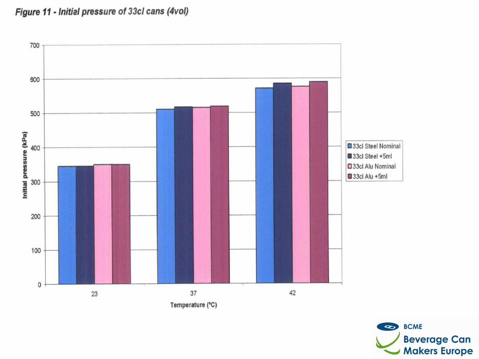
4.1 Extreme Environmental Evaluation The objective of this study for 330ml cans, undertaken by PIRA, was to:
Determine the maximum pressure that occurs within a 330ml beverage can, during its life cycle; and
Measure the changes in the can height growth and volume change that take place as a result of elevated
temperatures.
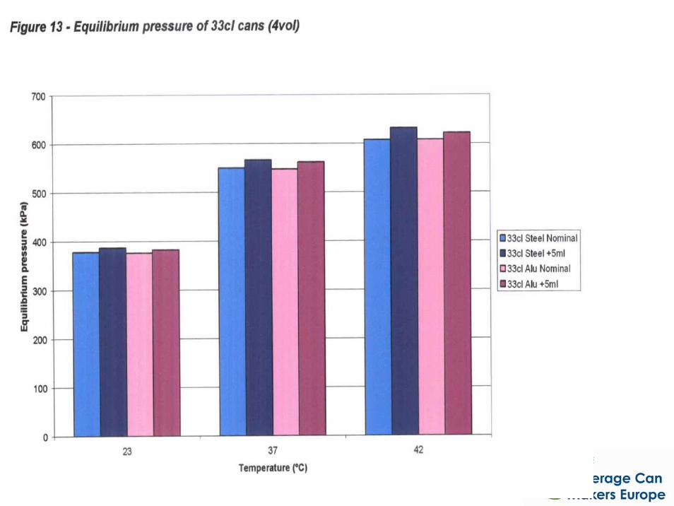
As this project covered both beer and carbonated soft drinks, a range of temperatures were evaluated to mimic beer pasteurization, hot fill applications and extreme temperatures post filling. Due to time constraints, the initial testing was completed for soft drink 330ml cans only. Testing will continue and formulae will be developed which will yield the necessary information on In-Can-Pressures for Beer and Soft Drinks, including different temperatures and carbonation levels. However, the performance specification for 330ml cans was very positive. Internal pressures for the 330ml are around the 600kPA mark, with elevated temperatures at 42ºC for 24hours, but this scenario is not very likely. The interim report can be found in Appendix 5. The PIRA study, funded by WRAP, was crucial in exploring the actual "in-can-presures" and the resulting growth of the can, the very first study of it's kind. Designing and building the experimental equipment to conduct the study took longer than expected, the final report will be completed by the end of 2008.
Lightweighting the can pack 15
5.0 Project Conclusion: A Positive Step to Further Lightweight the Can Pack The combined team of European can makers, The Coca-Cola Company, WRAP and filling partners (including the brands they fill for) has allowed a holistic approach to can lightweighting. The beverage can industry has very tight capacity in Europe; to change only one sector and not include all beverages, would be impossible to achieve. For this reason, all trials, and subsequent uptake of the midwall can lightweight specifications included not only Coca-Cola brands but also other major European brewers and beverage brands using aluminium cans manufactured by Rexam, Crown and Ball Packaging. From the outset, the aim of the project was to find the requirements of the life span of the can – how low can a can’s weight go? Various can sizes were studied and assumed beverage filling demands. Assumptions have been rigorously tested by highly reputable external laboratories and testing centres. Results have been validated through CCE’s manufacturing and distribution operations. The lightweighted cans have been in trade now for one year at two of CCE’s GB manufacturing facilities. The can does feel different, it has a thinner midwall. But, the new can specification has not had an adverse impact on consumer complaints in CCE. The project was able to prove that the new can specification was more than capable to withstand the internal and external forces in its life cycle. Data from this project suggests that further lightweighting opportunities are achievable, and the minimum performance limits of the can package are now better understood. The new specification may be applied for all can packages for all beverages, which could not have been achieved without the inclusion of the 3 main can manufacturers in Europe: Rexam, Ball and Crown working in conjunction on testing and validation. 5.1 Estimated per Annum Weight Reduction As a result of the lightweighting during the trial period, the following weight savings can be calculated on a per annum basis. The figures include aluminium can bodies and ends – material weight reduction. GB Coca-Cola
Enterprises (tonnes)
GB aluminium can industry
(tonnes)
EU aluminium can industry (tonnes)
Total aluminium saved per annum 1,147 2,819 14,974 Tonnes CO2 equivalent saved (if 100% virgin material used)
12,612 31,001 164,712
Tonnes CO2 equivalent saved (if 100% recycled content used)
2,293 5,638 29,948
RationalisationRationalisation of beverage of beverage can specificationscan specifications
A BCME study with methodology devised and
work programme conducted by Pira International
250ml Aluminium
250ml Steel
330ml Aluminium
330ml Steel
500ml Aluminium500ml Steel
Shaped 330ml Aluminium
1000
1500
2000
2500
3000
3500
4000
4500
0 10 20 30 40 50 60 70 80 90
Can internal pressure (adjusted)/psi
Mea
n fa
ilure
load
/N
Appendix 1.1: BCME (Pira study)
ObjectivesObjectives
• Phase 1 - To determine the axial load requirements for filled beverage cans (from the point of palletisation to the point of use by the consumer)
• Phase 2 - To establish the relationship between empty can axial load performance and filled can axial crush performance through evaluation of a range of factors that influence filled can top load strength (internal pressure and empty can specification)
Phase 1 Phase 1 -- Work Work programmeprogramme
• Loads on individual cans measured under laboratory controlled conditions
• Load measured during simulated pallet stacking
– This is the part of the supply process where the highest top loads arise
• Detailed set of experiments conducted
• 250ml, 330ml and 500ml cans evaluated
• Range of pallet type, stacking pattern, pallet stack height and other loading factors considered
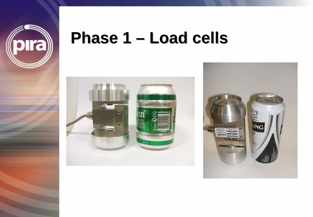
Phase 1 Phase 1 –– Load cellsLoad cells
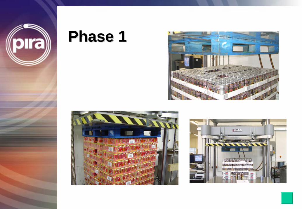
Phase 1Phase 1
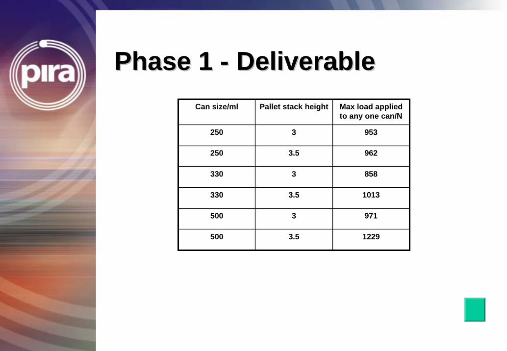
Phase 1 Phase 1 -- DeliverableDeliverableCan size/ml Pallet stack height Max load applied
to any one can/N
250 3 953
250 3.5 962
330 3 858
330 3.5 1013
500 3 971
500 3.5 1229
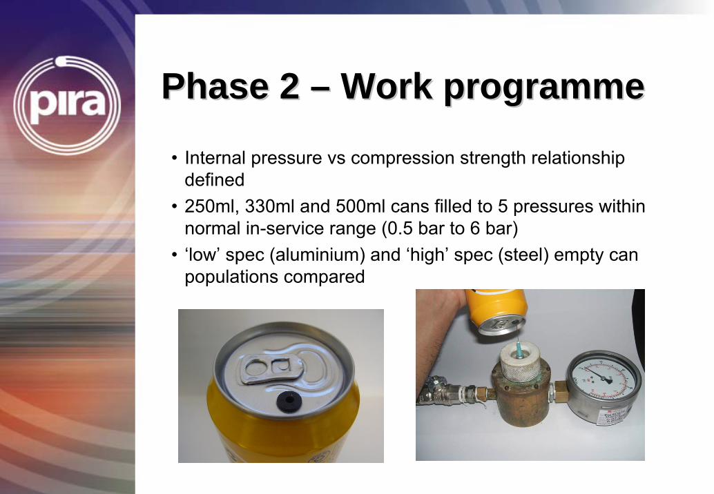
Phase 2 Phase 2 –– Work programmeWork programme
• Internal pressure vs compression strength relationship defined
• 250ml, 330ml and 500ml cans filled to 5 pressures within normal in-service range (0.5 bar to 6 bar)
• ‘low’ spec (aluminium) and ‘high’ spec (steel) empty can populations compared
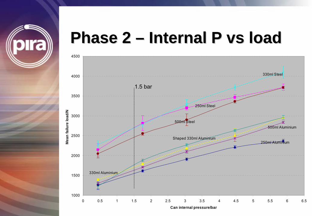
Phase 2 Phase 2 –– Internal P vs loadInternal P vs load
250ml Aluminium
250ml Steel
330ml Aluminium
330ml Steel
500ml Aluminium500ml Steel
Shaped 330ml Aluminium
1000
1500
2000
2500
3000
3500
4000
4500
0 0.5 1 1.5 2 2.5 3 3.5 4 4.5 5 5.5 6 6.5
Can internal pressure/bar
Mea
n fa
ilure
load
/N
1.5 bar
DiscussionDiscussion
• Gradients of steel curves and aluminium curves are similar
• This implies that the internal pressure versus filled seamed can compression strength relationship is consistent for different empty can specifications
• Equations can be reconfigured to allow calculation of F (empty can top load performance for new can specification)
• Thus equations can be used to evaluate light weighting opportunity for given internal pressure and for target filled seamed top load performance (now defined from Phase 1 work)
DiscussionDiscussion
For example for 330ml aluminium can
Phase 2 shows T = 283 P + 0.907 FTherefore F = (T – 283 P) / 0.907Thus for 1.5 bar F = (T – 425) / 0.907
F = empty can top load strength for new specification can (Newtons)
T = Design top load (Newtons) for individual filled seamed pressurised can (defined in Phase 1)
P = internal pressure (bar)
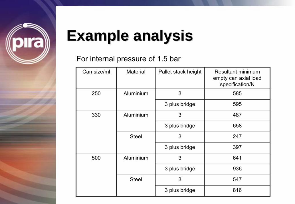
Example analysisExample analysis
Can size/ml Material Pallet stack height Resultant minimum empty can axial load
specification/N
3 585Aluminium
Aluminium
Steel
Aluminium
3 plus bridge 936
Steel
3 plus bridge 595
3 487
3 plus bridge 658
3 247
330
3 plus bridge 397
3 641
3 547
3 plus bridge 816
500
250
For internal pressure of 1.5 bar
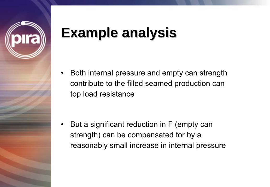
Example analysis Example analysis
• Both internal pressure and empty can strength contribute to the filled seamed production can top load resistance
• But a significant reduction in F (empty can strength) can be compensated for by a reasonably small increase in internal pressure
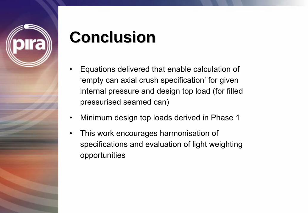
ConclusionConclusion
• Equations delivered that enable calculation of ‘empty can axial crush specification’ for given internal pressure and design top load (for filled pressurised seamed can)
• Minimum design top loads derived in Phase 1
• This work encourages harmonisation of specifications and evaluation of light weighting opportunities

End
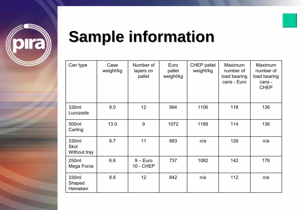
Sample informationSample informationCan type Case
weight/kgNumber of layers on
pallet
Euro pallet
weight/kg
CHEP pallet weight/kg
Maximum number of
load bearing cans - Euro
Maximum number of
load bearing cans -CHEP
330ml Lucozade
9.0 12 994 1106 118 136
500ml Carling
13.0 9 1072 1189 114 136
330ml SkolWithout tray
8.7 11 883 n/a 126 n/a
250ml Mega Force
6.6 9 – Euro10 - CHEP
737 1082 142 176
330ml ShapedHeineken
8.6 12 842 n/a 112 n/a
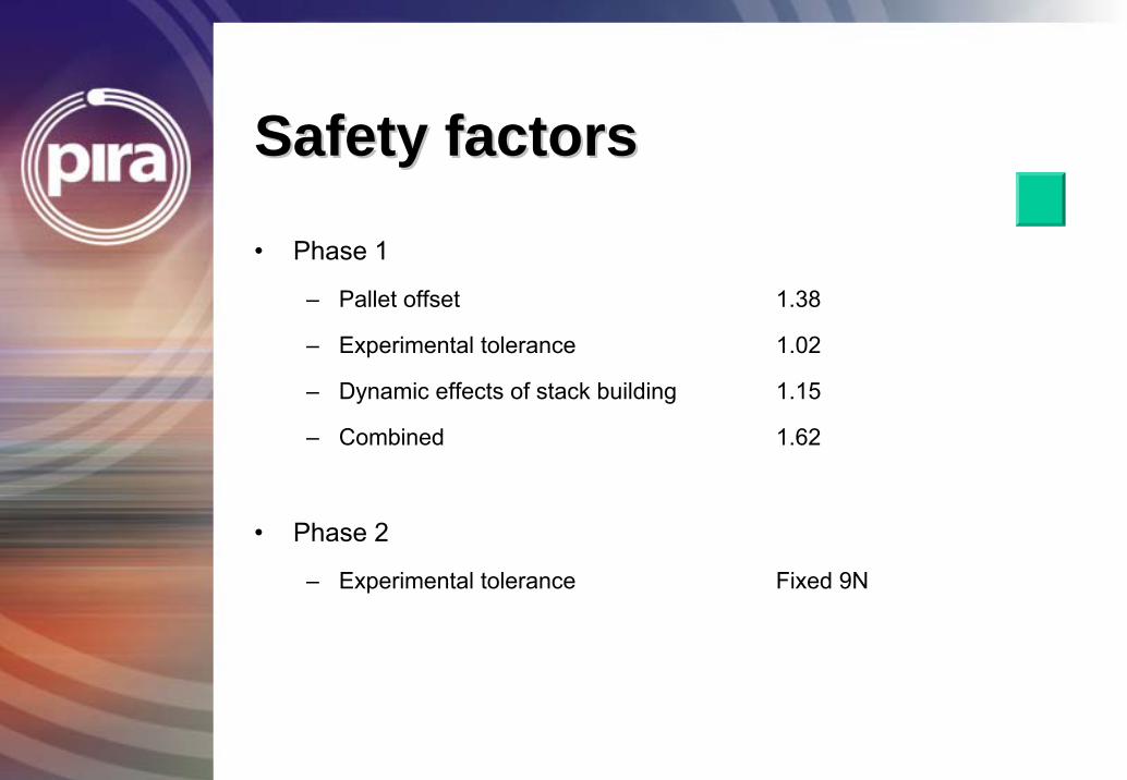
Safety factorsSafety factors
• Phase 1
– Pallet offset 1.38
– Experimental tolerance 1.02
– Dynamic effects of stack building 1.15
– Combined 1.62
• Phase 2
– Experimental tolerance Fixed 9N
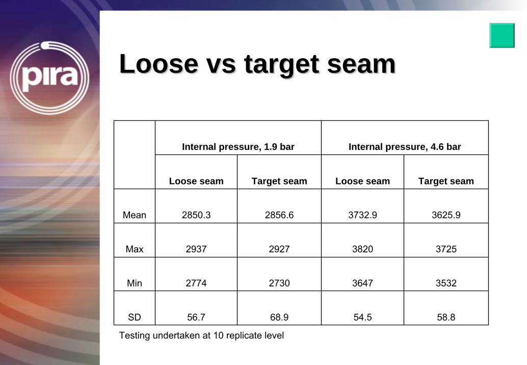
Loose Loose vsvs target seamtarget seam
Internal pressure, 1.9 bar Internal pressure, 4.6 bar
Loose seam Target seam Loose seam Target seam
Mean 2850.3 2856.6 3732.9 3625.9
Max 2937 2927 3820 3725
Min 2774 2730 3647 3532
SD 56.7 68.9 54.5 58.8
Testing undertaken at 10 replicate level
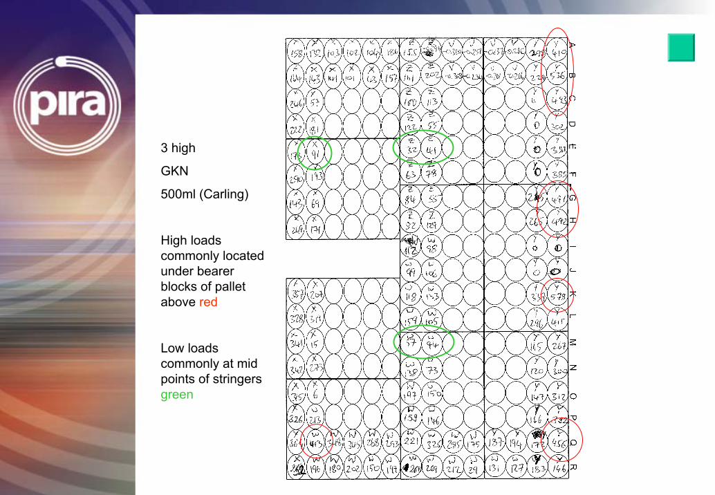
3 high
GKN
500ml (Carling)
High loads commonly located under bearer blocks of pallet above red
Low loads commonly at mid points of stringers green
Fit for purpose Specifications
Midwall Specification on Aluminium Cans.
Midwall Specification
• Agenda – Goal – Background – Current specifications – Proposals and approach – Opportunities
Midwall Specification
Goal To determine the most effective average
midwall performance of the can.
On completion the can should be fit for purposes, meet the customer performance
requirements and the consumers expectations.
Midwall Specification
• Background – A minimum average midwall thickness specification was previously set in Europe to address perceived risks, such as • Midwall perforations • Crushing during filling • Puncture resistance • Body wall damage
– The determined specification would ensure that the can was fit for purpose and remained undamaged.
Midwall Specification
• Current performance – Pan European Spec V9 gave midwall as
• To be supplied ± 0.01mm Minimum average 102µm
– European specification developed to ensure axial load performance requirements are met and perceived risks are addressed
– Dimensional specification set to address performance requirement
– Side wall puncture test developed to determine difference in mid wall performance
Midwall Specification
• Approach Used – Cans were manufactured with a range of mid wall values
– Measurements were taken for • Axial load • Side wall puncture • Drop test
– Results were analysed and confirmed that populations are statistically similar
– Extended trials were carried out and confirmed good Can Manufacturing Performance, as well as good performance on the Filling Line and in the Trade.
Midwall Specification
• Opportunities – Determine performance related midwall specification for beverage cans
– Light weighting on current gauge – Further downgauge opportunities
Mid wall results
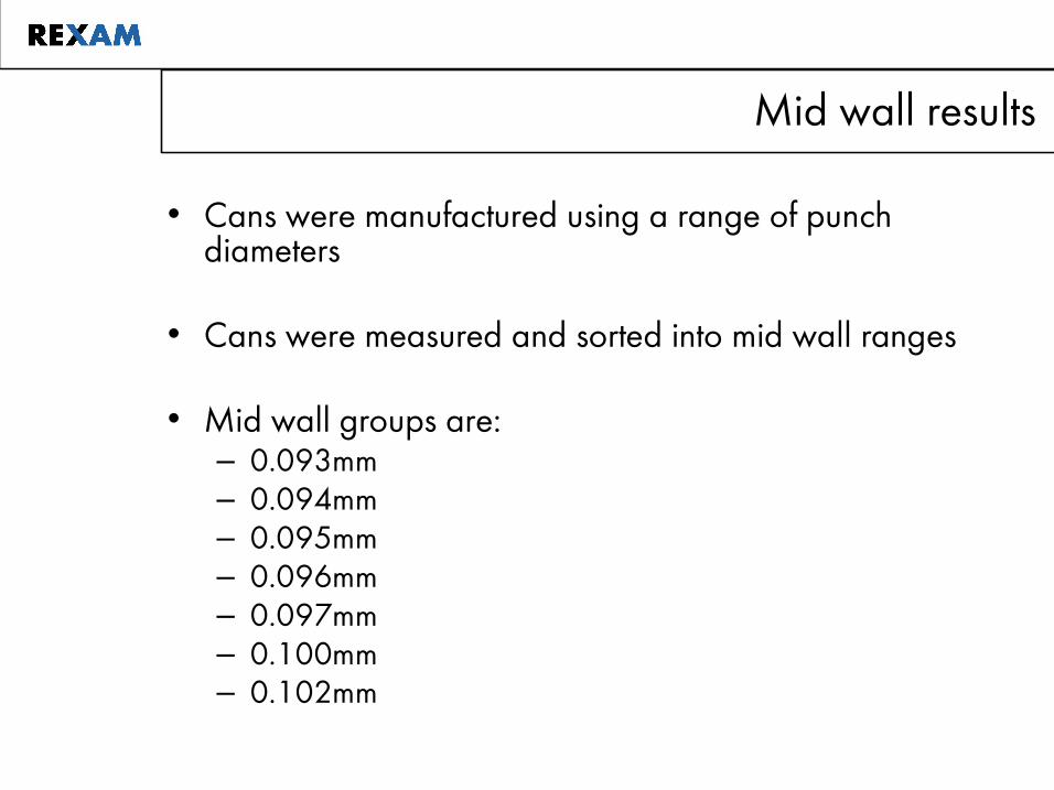
• Cans were manufactured using a range of punch diameters
• Cans were measured and sorted into mid wall ranges
• Mid wall groups are: – 0.093mm – 0.094mm – 0.095mm – 0.096mm – 0.097mm – 0.100mm – 0.102mm
Mid wall results
• 24 cans from each group were tested for axial load performance
• Coke CART and Drop test results were completed, with satisfactory results.
Mid wall results
MW
Axial
0.102 0.100 0.098 0.096 0.094 0.092
1200
1150
1100
1050
1000
950
900
850
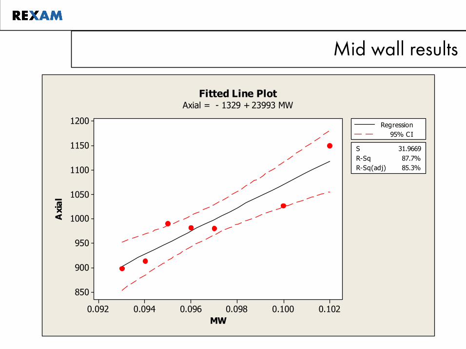
S 31.9669 RSq 87.7% RSq(adj) 85.3%
Regression 95% CI
Fitted Line Plot Axial = 1329 + 23993 MW
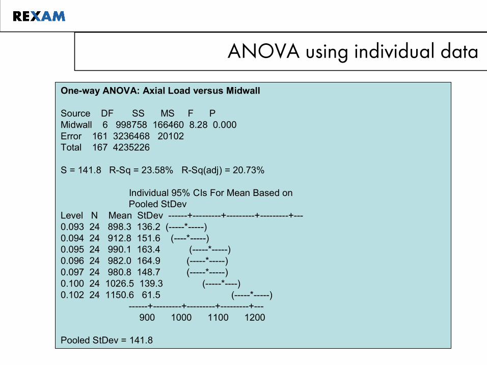
ANOVA using individual data
Oneway ANOVA: Axial Load versus Midwall
Source DF SS MS F P Midwall 6 998758 166460 8.28 0.000 Error 161 3236468 20102 Total 167 4235226
S = 141.8 RSq = 23.58% RSq(adj) = 20.73%
Individual 95% CIs For Mean Based on Pooled StDev
Level N Mean StDev ++++ 0.093 24 898.3 136.2 (*) 0.094 24 912.8 151.6 (*) 0.095 24 990.1 163.4 (*) 0.096 24 982.0 164.9 (*) 0.097 24 980.8 148.7 (*) 0.100 24 1026.5 139.3 (*) 0.102 24 1150.6 61.5 (*)
++++ 900 1000 1100 1200
Pooled StDev = 141.8
Manufacturing Line Trials
• On the basis of the Tests carried out on Axial Load for the different Midwall Thicknesses ,Manufacturing Line Trials of 0.097mm Midwall 33cl Aluminum Cans at Rexam Wakefield plant, then carried out Filling Line Trials :---
T1 Trial to check the Seaming Performance , to check the compatibility with the previous Can. These were successfully carried out at CCE Milton Keynes and CCE Wakefield
T2 Trial to check the performance of the new Cans from 7 Bodymakers at both CCE Milton Keynes and CCE Wakefield, which were closely monitored before they were confirmed as being successful.
Manufacturing Line Trials
• On the basis of the successful Trials we started to convert the remaining Wakefield Bodymakers to 0.097mm Midwall and carried out a 48 Hour Process Capability Trial, as per the Coke Procedure. These were successful and verified the Results of the La Trials on Axial Crush, still meeting the original Axial Crush Specification of 800 Newtons
• The Data from the 48 Hour Trial , as well as Cans for Cart and Drop Test were forwarded to CCE / Coca-Cola Brussels for Approval, which was received, allowing us to progress the Supply of the Wakefield 0.097mm Midwall Can to other Coca-Cola Filling Sites
Manufacturing Line Trials
• We then carried out longer Filling Runs at the CCE Filling Sites in the UK and with our other Customers supplied by Rexam Wakefield, all of which were successful, except some issues at CCE Sidcup which were not related to the new Can Specs. This had no effect on our Conversion , as we are not normally a Supplier to CCE Sidcup
• The above exercise was repeated again on Cans produced by Rexam Milton Keynes, with similar results achieved and Milton Keynes converted to the new Specification in March 2008
• Since March 2008, all Aluminum Cans supplied to CCE UK by Rexam have been to the new Specification.
Discussion and Summary
• Because of the Systems / Instrumentation used in the Can Making Process, we have got a high level of Data to allow the Midwall thickness to be achieved within the agreed Specifications, by identifying any need for intervention on individual Bodymakers
• Because of the fact that the Project has been progressed using Scientific Data to work towards Fit-for-Purpose Specifications in a controlled manner by Customer / Supplier, it has been a success achieved within a relatively tight Time Schedule
• The work on the Midwalls was undertaken on behalf of the Canmaking Industry by Rexam, but involved input from other BCME Members on an ongoing basis with all information being shared.
Discussion and Summary
• No negative feedback has been received from Customers on the performance of Cans manufactured to the new Specification
• The work carried out on the PIRA Axial Crush Study would tend to suggest that there is still an opportunity to Lightweight the Aluminum Can further, while still retaining the Fit-for-Purpose approach. Lab Trials will be undertaken to verify whether this is the case.
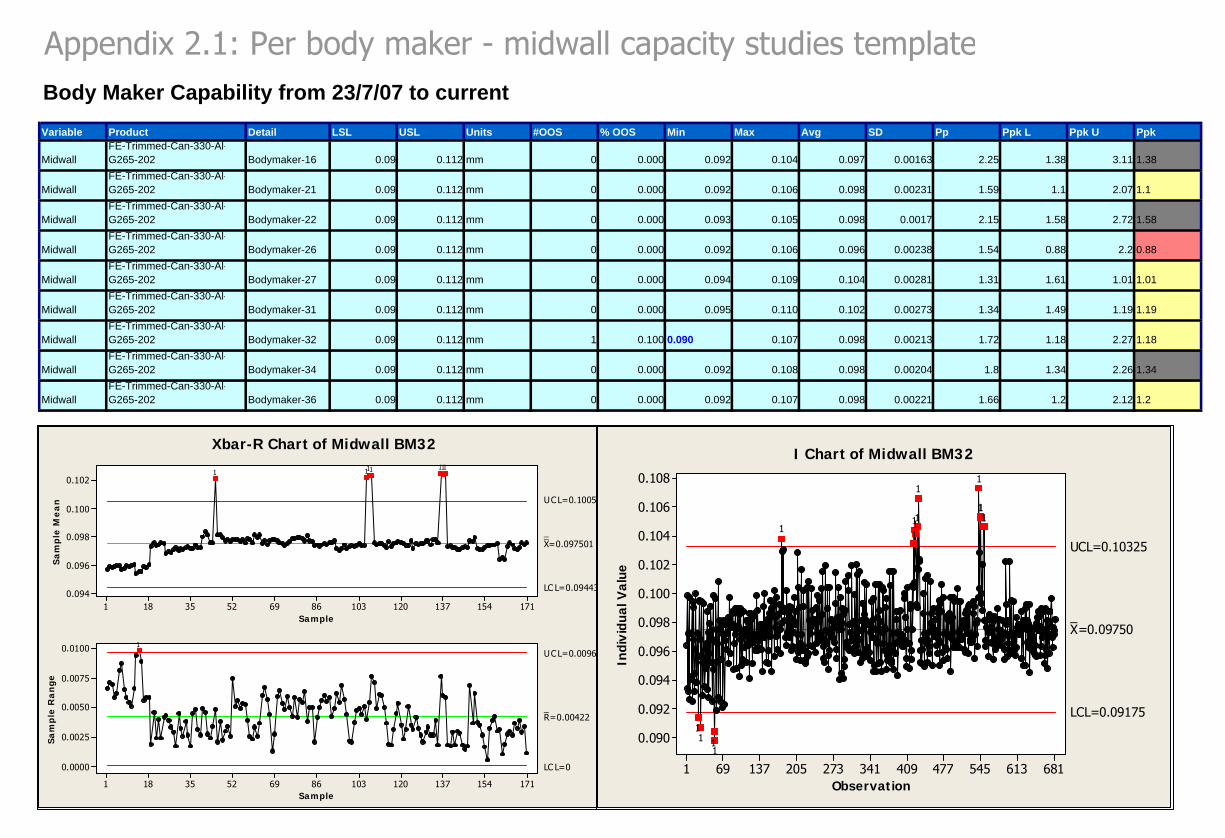
Appendix 2.1: Per body maker - midwall capacity studies templateBody Maker Capability from 23/7/07 to currentVariable Product Detail LSL USL Units #OOS % OOS Min Max Avg SD Pp Ppk L Ppk U Ppk
MidwallFE-Trimmed-Can-330-Al-G265-202 Bodymaker-16 0.09 0.112 mm 0 0.000 0.092 0.104 0.097 0.00163 2.25 1.38 3.11 1.38
MidwallFE-Trimmed-Can-330-Al-G265-202 Bodymaker-21 0.09 0.112 mm 0 0.000 0.092 0.106 0.098 0.00231 1.59 1.1 2.07 1.1
MidwallFE-Trimmed-Can-330-Al-G265-202 Bodymaker-22 0.09 0.112 mm 0 0.000 0.093 0.105 0.098 0.0017 2.15 1.58 2.72 1.58
MidwallFE-Trimmed-Can-330-Al-G265-202 Bodymaker-26 0.09 0.112 mm 0 0.000 0.092 0.106 0.096 0.00238 1.54 0.88 2.2 0.88
MidwallFE-Trimmed-Can-330-Al-G265-202 Bodymaker-27 0.09 0.112 mm 0 0.000 0.094 0.109 0.104 0.00281 1.31 1.61 1.01 1.01
MidwallFE-Trimmed-Can-330-Al-G265-202 Bodymaker-31 0.09 0.112 mm 0 0.000 0.095 0.110 0.102 0.00273 1.34 1.49 1.19 1.19
MidwallFE-Trimmed-Can-330-Al-G265-202 Bodymaker-32 0.09 0.112 mm 1 0.100 0.090 0.107 0.098 0.00213 1.72 1.18 2.27 1.18
MidwallFE-Trimmed-Can-330-Al-G265-202 Bodymaker-34 0.09 0.112 mm 0 0.000 0.092 0.108 0.098 0.00204 1.8 1.34 2.26 1.34
MidwallFE-Trimmed-Can-330-Al-G265-202 Bodymaker-36 0.09 0.112 mm 0 0.000 0.092 0.107 0.098 0.00221 1.66 1.2 2.12 1.2
17115413712010386695235181
0.102
0.100
0.098
0.096
0.094
Sample
Sa
mp
le M
ea
n
__X=0.097501
UCL=0.100573
LC L=0.094430
17115413712010386695235181
0.0100
0.0075
0.0050
0.0025
0.0000
Sample
Sa
mp
le R
an
ge
_R=0.00422
UCL=0.00962
LC L=0
1111111
1
Xbar-R Chart of Midwall BM32
681613545477409341273205137691
0.108
0.106
0.104
0.102
0.100
0.098
0.096
0.094
0.092
0.090
Observation
Indi
vidu
al V
alue
_X=0.09750
UCL=0.10325
LCL=0.09175
1111
11
11111
111
1
I Chart of Midwall BM32
Packaging Supplier Capability Study
Package Type: 330ml CANS Date:
16.10.7
Guidelines This document is a guideline for conducting a capability study. This capability study is part of the technical product authorization process. It is preferred to get individual measurement results. Please specify if the values would be the average of several measurements on the same can. The final capability study report must be delivered in a Word document (this document). This document includes:
- General information - Test Setup - Process capability study - Graphs - Remarks per parameter
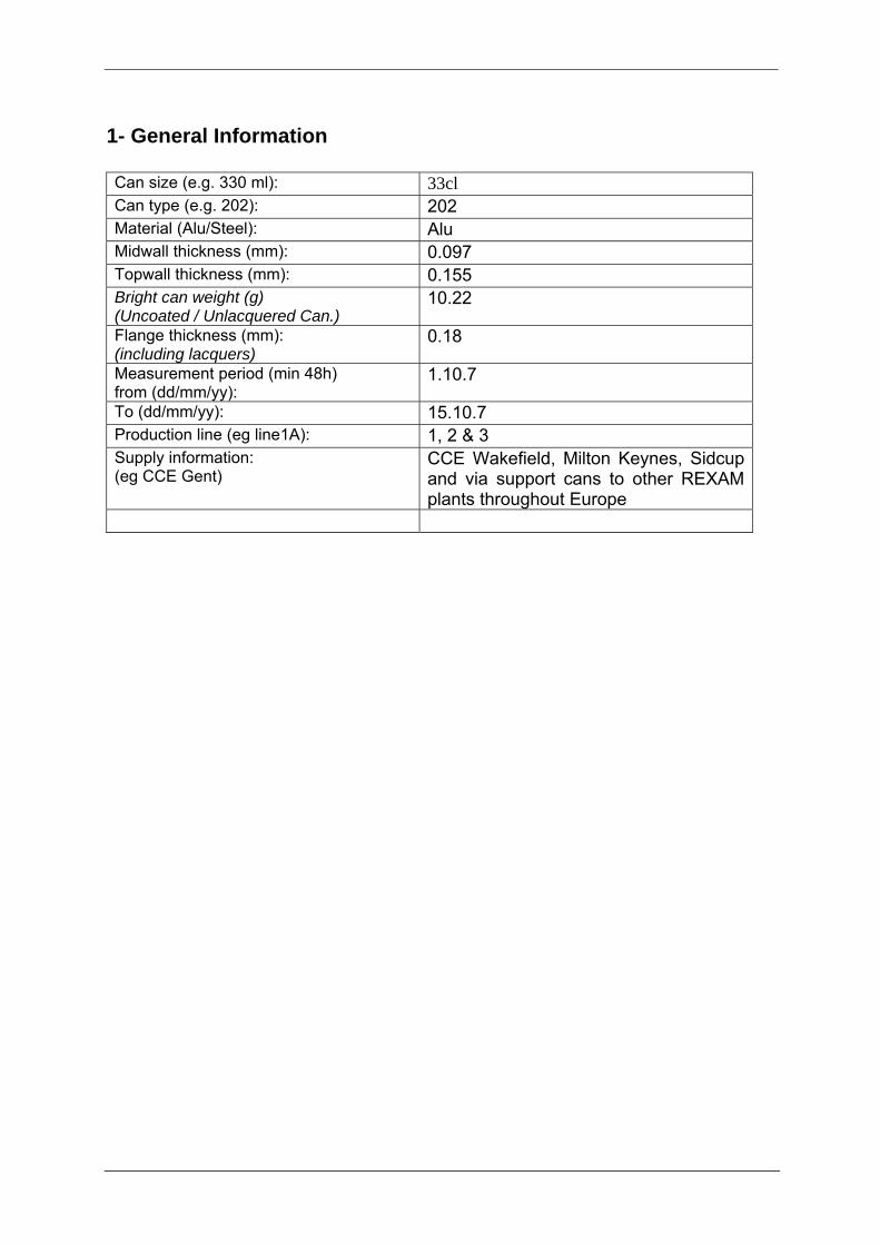
1- General Information Can size (e.g. 330 ml): 33cl Can type (e.g. 202): 202 Material (Alu/Steel): Alu Midwall thickness (mm): 0.097 Topwall thickness (mm): 0.155 Bright can weight (g) (Uncoated / Unlacquered Can.)
10.22
Flange thickness (mm): (including lacquers)
0.18
Measurement period (min 48h) from (dd/mm/yy):
1.10.7
To (dd/mm/yy): 15.10.7 Production line (eg line1A): 1, 2 & 3 Supply information: (eg CCE Gent)
CCE Wakefield, Milton Keynes, Sidcup and via support cans to other REXAM plants throughout Europe
2- Study Set Up
- In order to reduce the statistical error, at least 400 values per parameter are needed for Cpk calculations (400 individual Cans). For example, if a parameter is measured 3 times on one can, at least 3 x 400 measurements have to be supplied.
- For buckle strength at least 300 samples have to be taken (regardless previous remarks).
- All values should be results of individual measurements (no averages of multiple measurements). If average values are supplied, this should be clearly mentioned in the report.
- The measurement period should be no less than 48hours of production. - It is allowed to exclude data point belonging to product which has been
isolated and scrapped. Any product subsequently released for supply is to be included in the data set (this must be mentioned in the report).
- In addition to the Cpk-values (Normal distributions) the non-normal Cpk (Cpknn) should be calculated.
- All process capability indicators should be calculated against the latest version of Coca-Cola Specifications (the latest specifications can be obtained from the Packaging Supply Quality Group)
A guideline for acceptable performance is: Cpk > 1 for multiple individual measurements per Can. Cpk > 1,33 for average measurements or for single individual measurements per Can. e.g: The flange width is measured 3 times per Can. The three individual values should be supplied. If the plant can only supply the average of the three measurements, it should be clearly stated in the report.
3- Remarks from the can maker The can maker is invited to add any remarks concerning this capability study in this section:
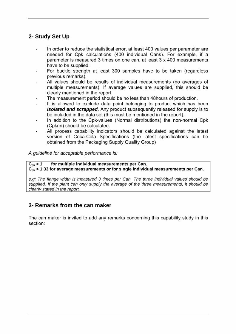
4- Capability Summary: line 1 Area No. of
Values Average Units Stand. Dev. Min. Max. Cp Cpk Cpknn ⎜d⎜ TCCC Specs
Can height (Individual) 1704 115.207 mm 0.080 114.907 115.476 1.25 1.22 0.007 115.2 mm ± 0.3
⎜d⎜<0.07
Axial load 440 1120 N 64.75 805 1199 1.65 Min 800N
Buckle strength 559 6.935 Bar 0.129 6.56 7.23 1.88 Min 6.2bar
Enamel Rater 1148 0.394 mA 0.56 0.00 16.80 9.82
(Alu) 17 mA ind max. 2 mA avg.
(Steel) 2 mA ind max 0.5 mA avg
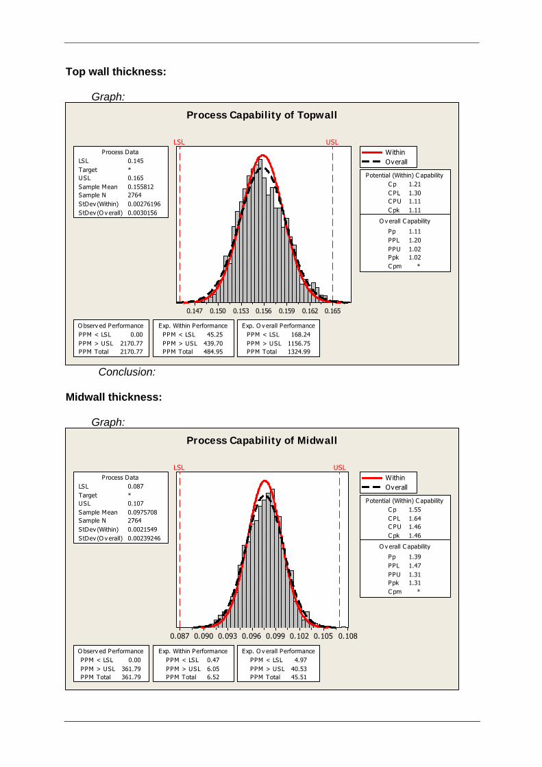
Top-wall thickness (Individual) 2764 0.1558 mm 0.003 0.1467 0.1669 1.11 1.02 0.0008 ± 0.01
Mid-wall thickness (Individual) 2764 0.0976 mm 0.0024 0.0893 0.1077 1.39 1.31 0.0006 ± 0.01
Drop Test 24 12.79 cm 2.47 8.0 17.0
min 8 cm ind. min 10 cm avg
No drop in Performance
CART Test (Can Abuse Resistance Test)
24 .55 mA 0.31 0.1 1.4 No drop in Performance
• Individual results for the drop-test and can abuse resistance test must be given. • For design changes, the drop-test and can abuse resistance test must be conducted on the old and new design. • The nomenclature ⎜d⎜<0.06 equals the absolute value abs (avg - target) is less than 0.06. • Only the non-Normal distribution is acceptable for the ER Cpkn,
Line 2 Area No. of
Values Average Units Stand. Dev. Min. Max. Cp Cpk Cpknn ⎜d⎜ TCCC Specs
Can height (Individual) 1596 115.164 mm 0.072 114.904 115.442 1.38 1.22 0.036 115.2 mm ± 0.3
⎜d⎜<0.07
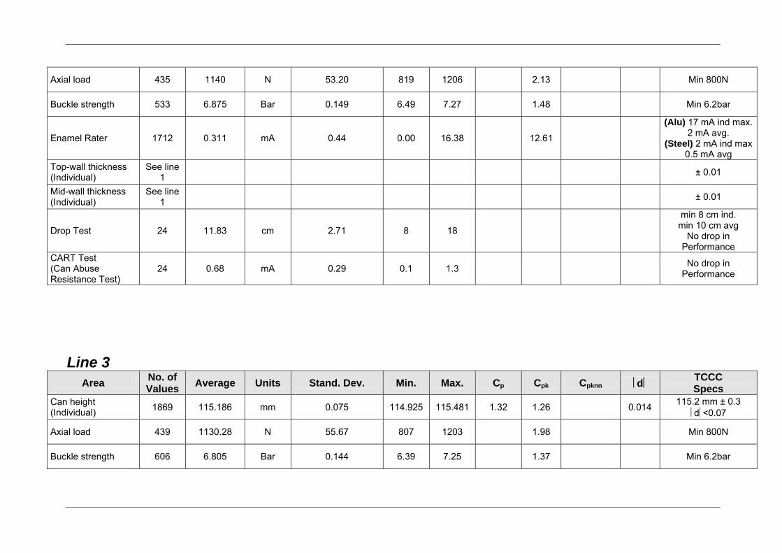
Axial load 435 1140 N 53.20 819 1206 2.13 Min 800N
Buckle strength 533 6.875 Bar 0.149 6.49 7.27 1.48 Min 6.2bar
Enamel Rater 1712 0.311 mA 0.44 0.00 16.38 12.61
(Alu) 17 mA ind max. 2 mA avg.
(Steel) 2 mA ind max 0.5 mA avg
Top-wall thickness (Individual)
See line 1 ± 0.01
Mid-wall thickness (Individual)
See line 1 ± 0.01
Drop Test 24 11.83 cm 2.71 8 18
min 8 cm ind. min 10 cm avg
No drop in Performance
CART Test (Can Abuse Resistance Test)
24 0.68 mA 0.29 0.1 1.3 No drop in Performance
Line 3 Area No. of
Values Average Units Stand. Dev. Min. Max. Cp Cpk Cpknn ⎜d⎜ TCCC Specs
Can height (Individual) 1869 115.186 mm 0.075 114.925 115.481 1.32 1.26 0.014 115.2 mm ± 0.3
⎜d⎜<0.07
Axial load 439 1130.28 N 55.67 807 1203 1.98 Min 800N
Buckle strength 606 6.805 Bar 0.144 6.39 7.25 1.37 Min 6.2bar
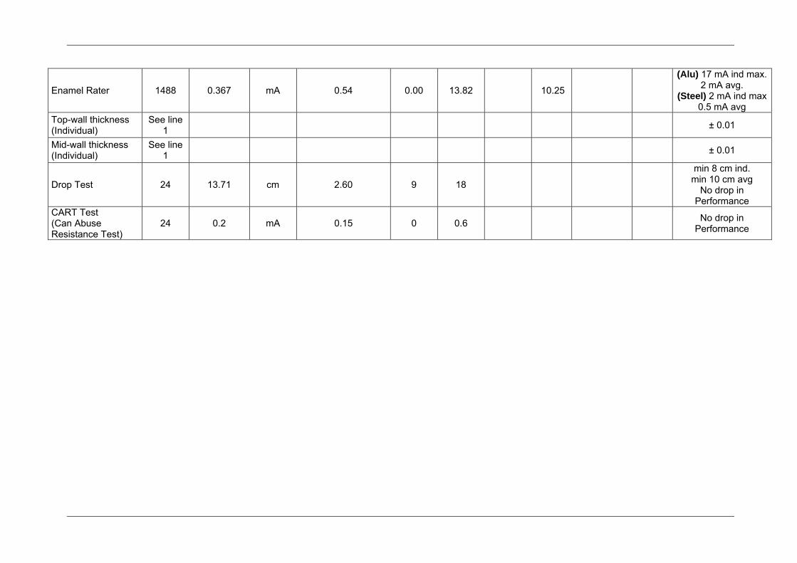
Enamel Rater 1488 0.367 mA 0.54 0.00 13.82 10.25
(Alu) 17 mA ind max. 2 mA avg.
(Steel) 2 mA ind max 0.5 mA avg
Top-wall thickness (Individual)
See line 1 ± 0.01
Mid-wall thickness (Individual)
See line 1 ± 0.01
Drop Test 24 13.71 cm 2.60 9 18
min 8 cm ind. min 10 cm avg
No drop in Performance
CART Test (Can Abuse Resistance Test)
24 0.2 mA 0.15 0 0.6 No drop in Performance
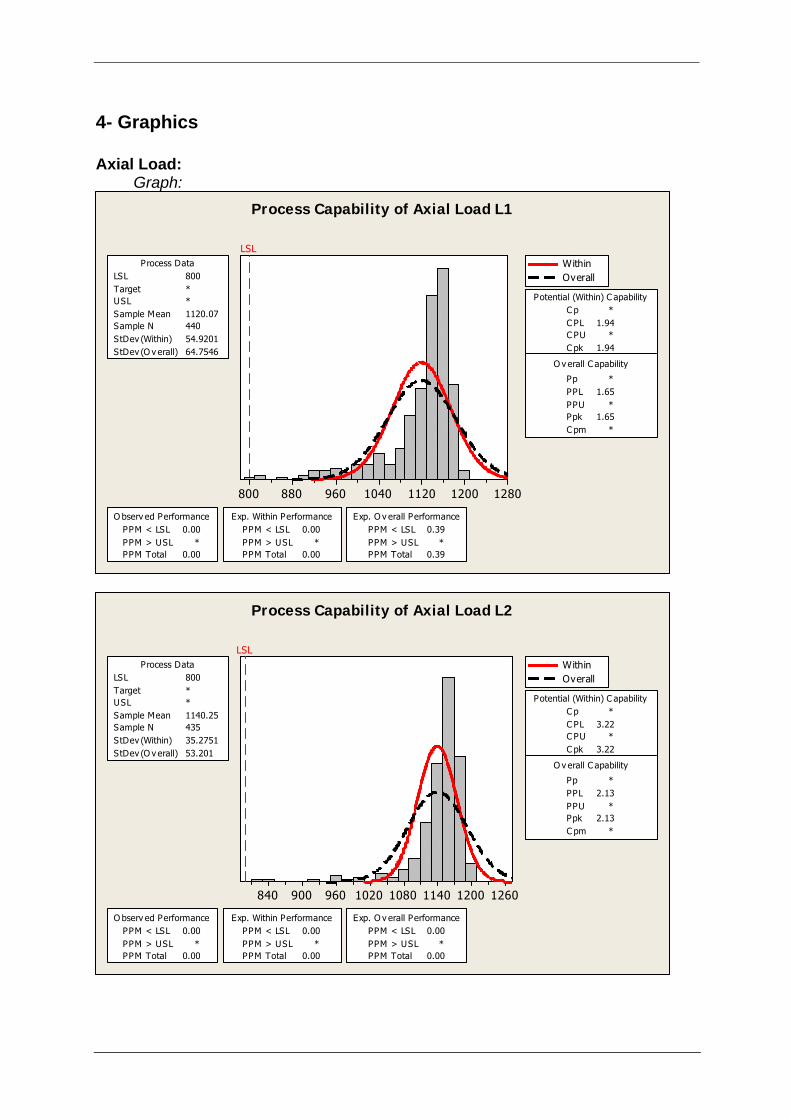
4- Graphics Axial Load: Graph:
1280120011201040960880800
LSL
LSL 800Target *USL *Sample Mean 1120.07Sample N 440StDev (Within) 54.9201StDev (O v erall) 64.7546
Process Data WithinOverall
Process Capability of Axial Load L1
Potential (Within) C apabilityC p *C PL 1.94C PU *C pk 1.94
Pp *PPL 1.65PPU *Ppk 1.65C pm *
O v erall C apability
PPM < LSL 0.00PPM > USL *PPM Total 0.00
O bserv ed PerformancePPM < LSL 0.00PPM > USL *PPM Total 0.00
Exp. Within PerformancePPM < LSL 0.39PPM > USL *PPM Total 0.39
Exp. O v erall Performance
12601200114010801020960900840
LSL
LSL 800Target *USL *Sample Mean 1140.25Sample N 435StDev (Within) 35.2751StDev (O v erall) 53.201
Process Data WithinOverall
Process Capability of Axial Load L2
Potential (Within) C apabilityC p *C PL 3.22C PU *C pk 3.22
Pp *PPL 2.13PPU *Ppk 2.13C pm *
O v erall C apability
PPM < LSL 0.00PPM > USL *PPM Total 0.00
O bserv ed PerformancePPM < LSL 0.00PPM > USL *PPM Total 0.00
Exp. Within PerformancePPM < LSL 0.00PPM > USL *PPM Total 0.00
Exp. O v erall Performance
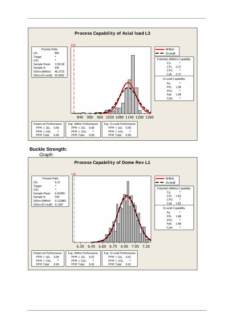
12601200114010801020960900840
LSL
LSL 800Target *USL *Sample Mean 1130.28Sample N 439StDev (Within) 46.3725StDev (O v erall) 55.6692
Process Data WithinOverall
Process Capability of Axial load L3
Potential (Within) C apabilityC p *C PL 2.37C PU *C pk 2.37
Pp *PPL 1.98PPU *Ppk 1.98C pm *
O v erall C apability
PPM < LSL 0.00PPM > USL *PPM Total 0.00
O bserv ed PerformancePPM < LSL 0.00PPM > USL *PPM Total 0.00
Exp. Within PerformancePPM < LSL 0.00PPM > USL *PPM Total 0.00
Exp. O v erall Performance
Buckle Strength: Graph:
7.207.056.906.756.606.456.30
LSL
LSL 6.21Target *USL *Sample Mean 6.93499Sample N 559StDev (Within) 0.132883StDev (O v erall) 0.1287
Process Data WithinOverall
Process Capability of Dome Rev L1
Potential (Within) C apabilityC p *C PL 1.82C PU *C pk 1.82
Pp *PPL 1.88PPU *Ppk 1.88C pm *
O v erall C apability
PPM < LSL 0.00PPM > USL *PPM Total 0.00
O bserv ed PerformancePPM < LSL 0.02PPM > USL *PPM Total 0.02
Exp. Within PerformancePPM < LSL 0.01PPM > USL *PPM Total 0.01
Exp. O v erall Performance
Top wall thickness: Graph:
0.1650.1620.1590.1560.1530.1500.147
LSL USL
LSL 0.145Target *USL 0.165Sample Mean 0.155812Sample N 2764StDev (Within) 0.00276196StDev (O v erall) 0.0030156
Process Data WithinOverall
Process Capability of Topwall
Potential (Within) C apabilityC p 1.21C PL 1.30C PU 1.11C pk 1.11
Pp 1.11PPL 1.20PPU 1.02Ppk 1.02C pm *
O v erall C apability
PPM < LSL 0.00PPM > USL 2170.77PPM Total 2170.77
O bserv ed PerformancePPM < LSL 45.25PPM > USL 439.70PPM Total 484.95
Exp. Within PerformancePPM < LSL 168.24PPM > USL 1156.75PPM Total 1324.99
Exp. O v erall Performance
Conclusion:
Midwall thickness: Graph:
0.1080.1050.1020.0990.0960.0930.0900.087
LSL USL
LSL 0.087Target *USL 0.107Sample Mean 0.0975708Sample N 2764StDev (Within) 0.0021549StDev (O v erall) 0.00239246
Process Data WithinOverall
Process Capability of Midwall
Potential (Within) C apabilityC p 1.55C PL 1.64C PU 1.46C pk 1.46
Pp 1.39PPL 1.47PPU 1.31Ppk 1.31C pm *
O v erall C apability
PPM < LSL 0.00PPM > USL 361.79PPM Total 361.79
O bserv ed PerformancePPM < LSL 0.47PPM > USL 6.05PPM Total 6.52
Exp. Within PerformancePPM < LSL 4.97PPM > USL 40.53PPM Total 45.51
Exp. O v erall Performance
Project Sheet_________________________________
CD – Form Effective Date: 12th June 2006 LE-001-CD-014.F3Issue: 2
Project No: PRJ1152 Date: 22nd March 2007 Author: D. Middleton Approved By: John Howlett Raised By / From: Christine Watson Subject: Light weight 330ml Can Trial Time scale: Two weeks Conclusion: See report Circulation: CCE
Project Sheet_________________________________
CD – Form Effective Date: 12th June 2006 LE-001-CD-014.F3Issue: 2
Package Specification: - Height = 114mm Diameter = 66mm Average Weight = 14.6g A limited number of cans provided for the trial created the need to identify types of vend mechanism rather than test the full range of vendors present in the CCE estate. Therefore the following units were configured* for 330ml can.: - Vendo V476 (V545/680) Vendo 392 (406) Dixie Narco 600E (276EX)
Dixie Narco 276E (276) Dixie Narco 5091 * Vendors using the same vend mechanism shown in brackets.
The testing commenced with the Vendo 476 and 392 as these vendors were expected to cause less wear and tear to the packages due to the mechanics of the vend mechanism. The Technician conducting the test filled each column configured for 330ml can to maximum. Each column was then selected in turn and the result recorded. The result of the test is as follows:- Vendo V476 (900 test vends with no damage to the package) Vendo 392 (900 test vends with no damage to the package)
Dixie Narco 600E (700 test vends. One can punctured. Possible
cause, number of times can passed through vend mechanism)
Dixie Narco 276E (450 test vends with no damage to package) Dixie Narco 5091 (430 test vends with no damage to package)
Conclusion The reduction in weight has had no effect on the suitability of the package, when containing carbonated product, for use in the CCE vendor estate. However if non carbonated product is to be vended in this package then further vend testing using the non carbonated product should be conducted.
Internal Lacquer ThicknessTCCC - BCME meeting
December 11, 2007

Fit for purpose Specifications
Internal Lacquer Thickness
Internal Lacquer Thickness
Agenda•Goal
•Background of Specification
•Current Specs and Performance
•Reason for Investigation
•Programme Proposal
•Opportunities
Goal
•To review the current minimum internal lacquerthickness and find a common industry standard, which ensures the agreed metal exposure limits
Internal Lacquer Thickness
Background
•The reason for the minimum inside lacquerthickness is:
•Protect the drink from direct contact with the cansurface and prevent for metal pick up and perforation.
•Ensure the confirmed shelf life of the filled product.
Internal Lacquer Thickness
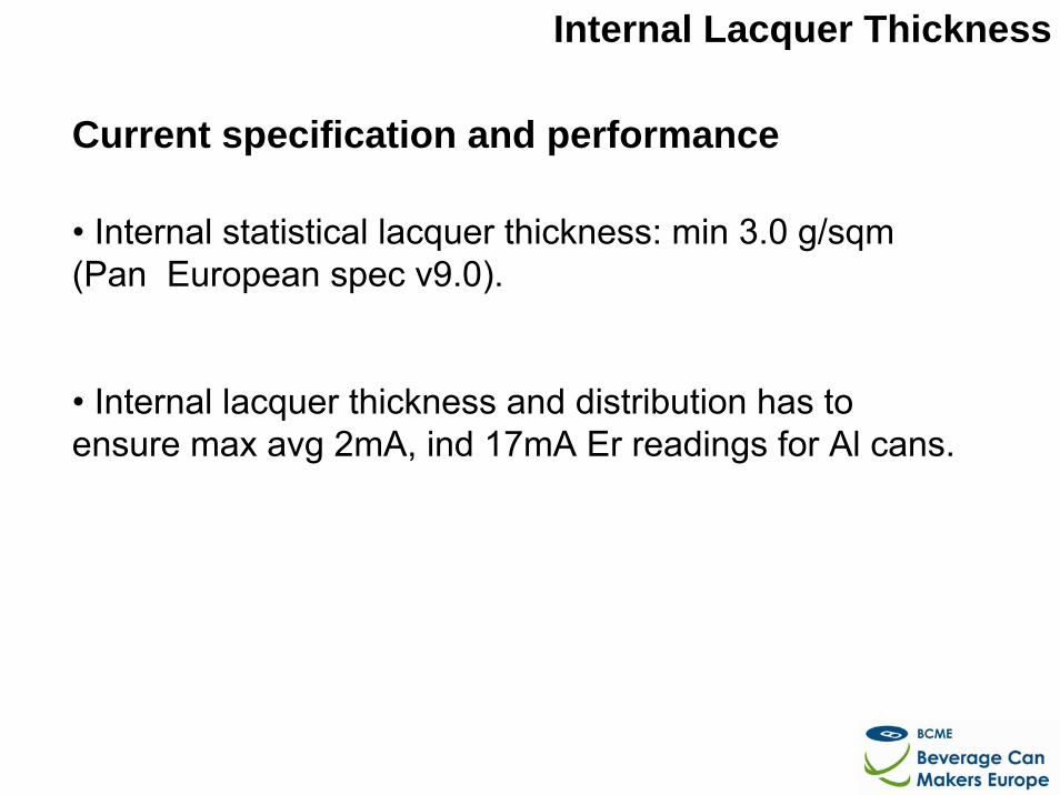
Current specification and performance
• Internal statistical lacquer thickness: min 3.0 g/sqm(Pan European spec v9.0).
• Internal lacquer thickness and distribution has to ensure max avg 2mA, ind 17mA Er readings for Al cans.
Internal Lacquer Thickness
Reason for investigation
•Review and define the statistical minimum insidelacquer thickness to fulfill metal exposure requirements.
Internal Lacquer Thickness
Programme Proposal
The BCME will arrange tests with 2pc alu 33cl cans:
•Sprayed with different filmweights/thickness.
•Determined for metal exposure.
Internal Lacquer Thickness
Opportunities
Opportunities
•Find a common internal lacquer thickness specfor the achievement of the metal exposure limits.
•Cost reduction potentials.
Internal Lacquer Thickness
Steps
1. Arrange 33cl alu cans with different internal lacquerthickness/weight
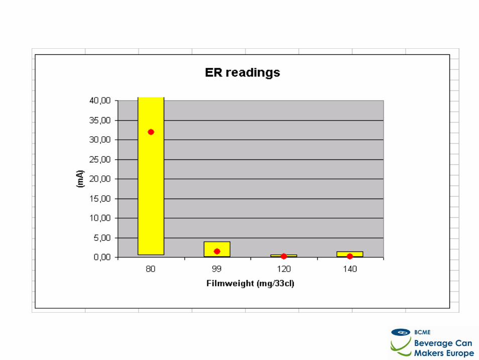
2. Measure ER
3. Set testpack programme
4. L85 results
5. Testpack results
6. Discussion and Proposal
Internal Lacquer Thickness
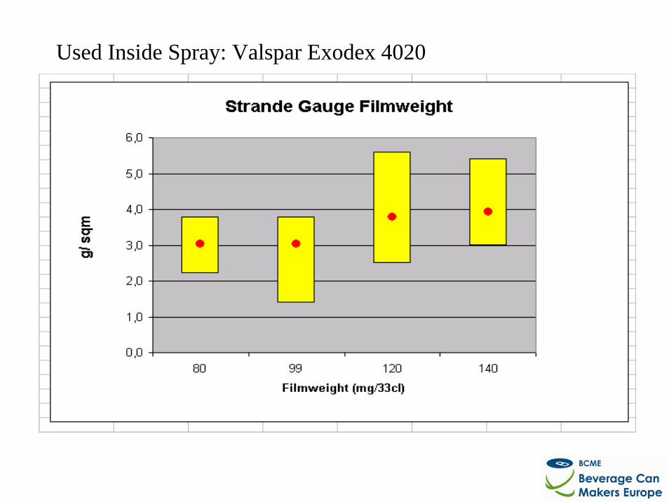
Used Inside Spray: Valspar Exodex 4020
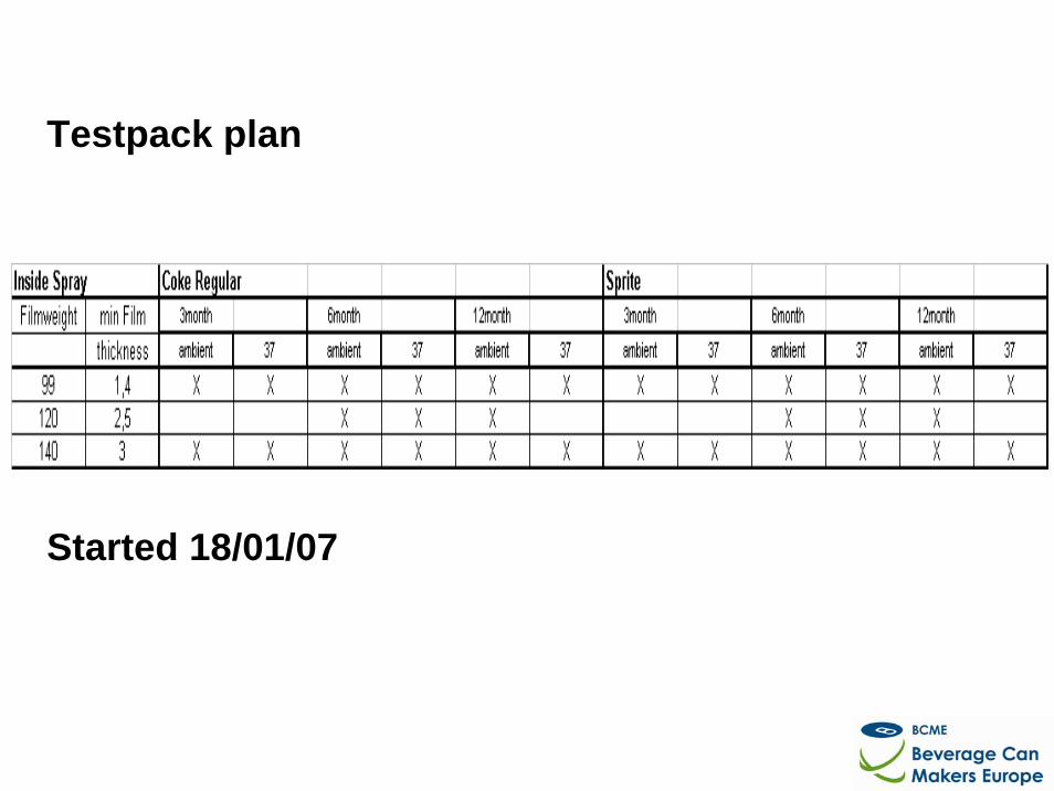
Testpack plan
Started 18/01/07
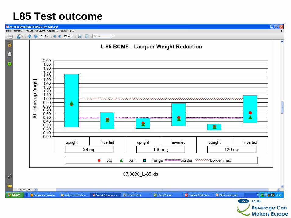
L85 Test outcome
99 mg 140 mg 120 mg
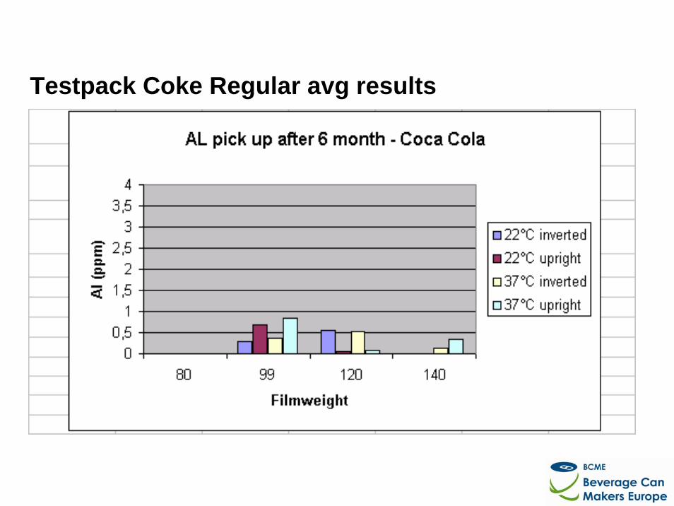
Testpack Coke Regular avg results
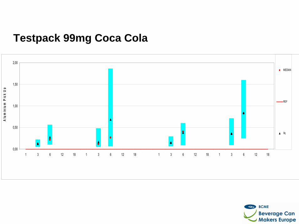
Testpack 99mg Coca Cola
0,00
0,50
1,00
1,50
2,00
1 3 6 12 18 1 3 6 12 18 1 3 6 12 18 1 3 6 12 18
Alu
min
ium
Pic
k U
p
MEDIAN
REF
Xq
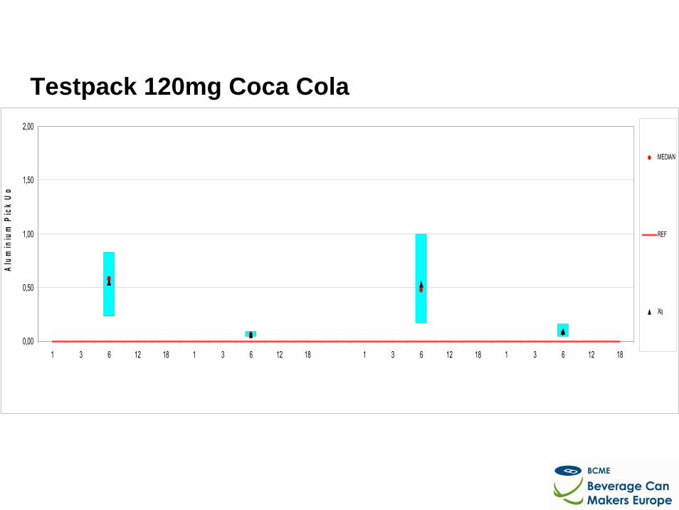
Testpack 120mg Coca Cola
0,00
0,50
1,00
1,50
2,00
1 3 6 12 18 1 3 6 12 18 1 3 6 12 18 1 3 6 12 18
Alu
min
ium
Pic
k U
p
MEDIAN
REF
Xq
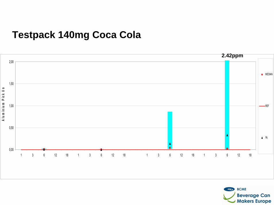
Testpack 140mg Coca Cola
0,00
0,50
1,00
1,50
2,00
1 3 6 12 18 1 3 6 12 18 1 3 6 12 18 1 3 6 12 18
Alu
min
ium
Pic
k U
p
MEDIAN
REF
Xq
2.42ppm
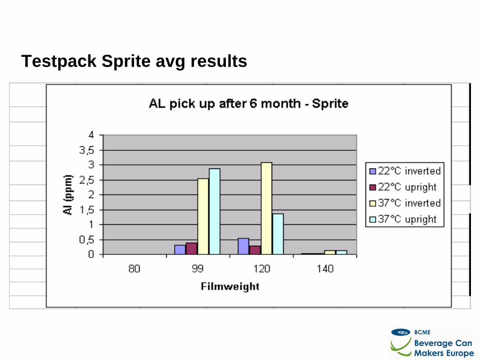
Testpack Sprite avg results
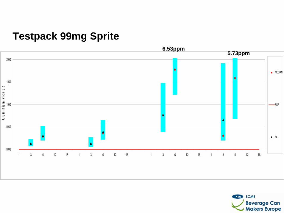
Testpack 99mg Sprite
0,00
0,50
1,00
1,50
2,00
1 3 6 12 18 1 3 6 12 18 1 3 6 12 18 1 3 6 12 18
Alu
min
ium
Pic
k U
p
MEDIAN
REF
Xq
5.73ppm6.53ppm
0,00
0,50
1,00
1,50
2,00
1 3 6 12 18 1 3 6 12 18 1 3 6 12 18 1 3 6 12 18
Alu
min
ium
Pic
k U
p
MEDIAN
REF
Xq
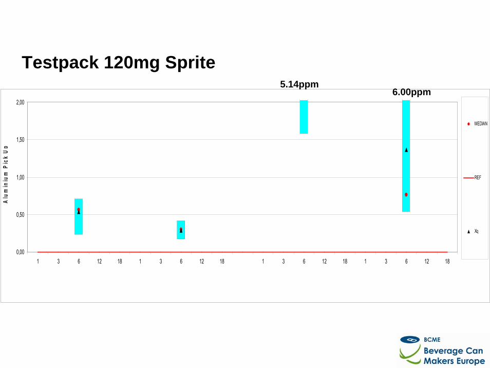
Testpack 120mg Sprite6.00ppm
5.14ppm
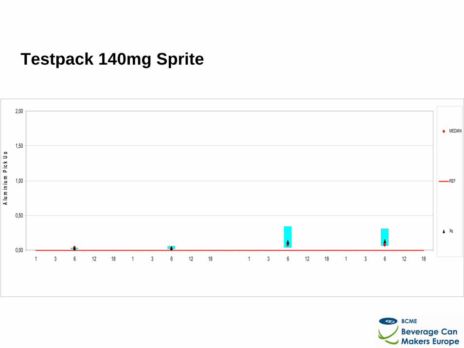
Testpack 140mg Sprite
0,00
0,50
1,00
1,50
2,00
1 3 6 12 18 1 3 6 12 18 1 3 6 12 18 1 3 6 12 18
Alu
min
ium
Pic
k U
p
MEDIAN
REF
Xq
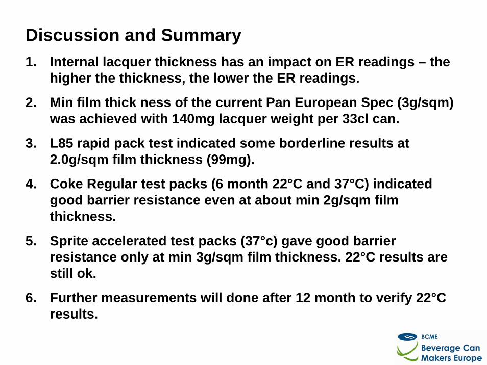
Discussion and Summary1. Internal lacquer thickness has an impact on ER readings – the
higher the thickness, the lower the ER readings.
2. Min film thick ness of the current Pan European Spec (3g/sqm) was achieved with 140mg lacquer weight per 33cl can.
3. L85 rapid pack test indicated some borderline results at 2.0g/sqm film thickness (99mg).
4. Coke Regular test packs (6 month 22°C and 37°C) indicated good barrier resistance even at about min 2g/sqm film thickness.
5. Sprite accelerated test packs (37°c) gave good barrier resistance only at min 3g/sqm film thickness. 22°C results are still ok.
6. Further measurements will done after 12 month to verify 22°C results.
Thank you for your Attention
BCME Technical CommitteeApril 24, 2008
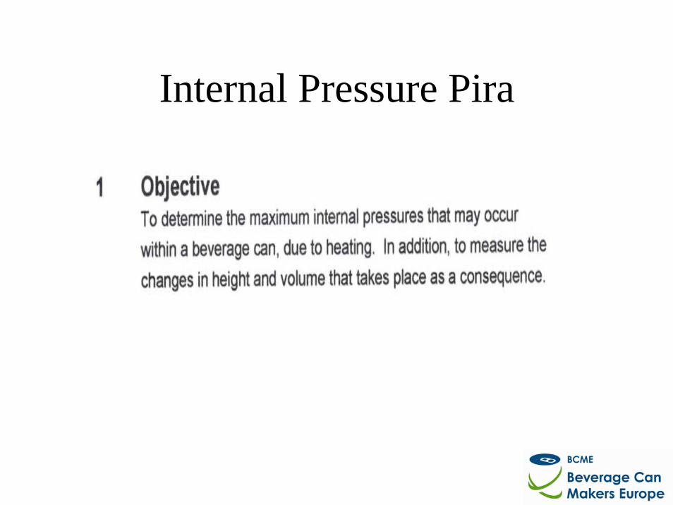
Internal Pressure Pira
423222
600
500
400
St 33 Temp
St 3
3 A
fter
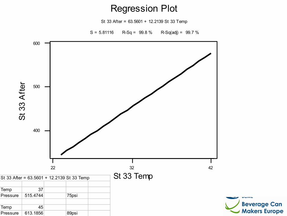
S = 5.81116 R-Sq = 99.8 % R-Sq(adj) = 99.7 %
St 33 After = 63.5601 + 12.2139 St 33 Temp
Regression Plot
St 33 After = 63.5601 + 12.2139 St 33 Temp
Temp 37Pressure 515.4744 75psi
Temp 45Pressure 613.1856 89psi
- While this is only an Interim Report, the 33cl Results on Unpasteurised Products look very encouraging.
- Even at Liquid Temperatures of 42 Degrees Centigrade over a 24 hour period, which is extremely unlikely, the maximum Internal Pressure of 600 KPA is less than the existing Specification of a minimum of 620KPA.
- The Correlation of results on 33cl Cans is good on the Trials to date.
- Further work in being undertaken by the BCME along with PIRA to give more detailed Results / Conclusions , not only for 33cl but also 50cl Cans. The Results will be available later in 2008 / early 2009.
Discussion and Summary
Thank you for your Attention

www.wrap.org.uk/retail