lilypad light sensor v2 hookup guide sheets/sparkfun... · lilypad light sensor v2 hookup guide...
TRANSCRIPT
LilyPad Light Sensor V2 Hookup Guide
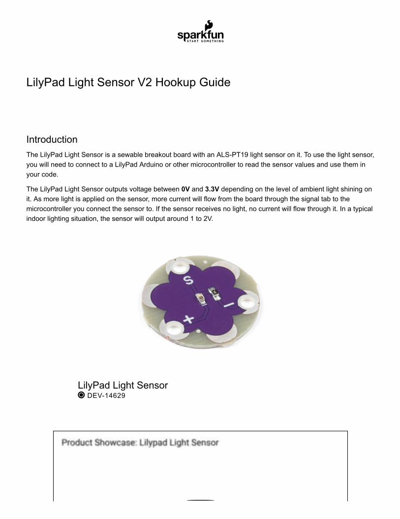
IntroductionThe LilyPad Light Sensor is a sewable breakout board with an ALS-PT19 light sensor on it. To use the light sensor,you will need to connect to a LilyPad Arduino or other microcontroller to read the sensor values and use them inyour code.
The LilyPad Light Sensor outputs voltage between 0V and 3.3V depending on the level of ambient light shining onit. As more light is applied on the sensor, more current will flow from the board through the signal tab to themicrocontroller you connect the sensor to. If the sensor receives no light, no current will flow through it. In a typicalindoor lighting situation, the sensor will output around 1 to 2V.
LilyPad Light Sensor DEV-14629
Product Showcase: Lilypad Light Sensor
YOUR ACCOUNT
LOG IN
REGISTER
LilyPad Light Sensor V2 Hookup Guide Wishlist SparkFun Wish List
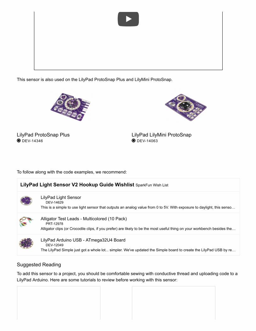
This sensor is also used on the LilyPad ProtoSnap Plus and LilyMini ProtoSnap.
To follow along with the code examples, we recommend:
LilyPad Light SensorDEV-14629
This is a simple to use light sensor that outputs an analog value from 0 to 5V. With exposure to daylight, this senso…
Alligator Test Leads - Multicolored (10 Pack)PRT-12978
Alligator clips (or Crocodile clips, if you prefer) are likely to be the most useful thing on your workbench besides the…
LilyPad Arduino USB - ATmega32U4 BoardDEV-12049
The LilyPad Simple just got a whole lot... simpler. We've updated the Simple board to create the LilyPad USB by re…
Suggested Reading
To add this sensor to a project, you should be comfortable sewing with conductive thread and uploading code to aLilyPad Arduino. Here are some tutorials to review before working with this sensor:
LilyPad ProtoSnap Plus DEV-14346
LilyPad LilyMini ProtoSnap DEV-14063
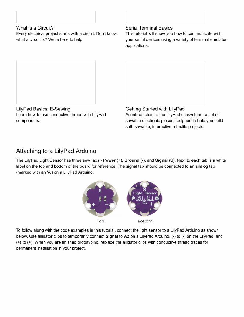
Attaching to a LilyPad ArduinoThe LilyPad Light Sensor has three sew tabs - Power (+), Ground (-), and Signal (S). Next to each tab is a whitelabel on the top and bottom of the board for reference. The signal tab should be connected to an analog tab(marked with an ‘A’) on a LilyPad Arduino.
To follow along with the code examples in this tutorial, connect the light sensor to a LilyPad Arduino as shownbelow. Use alligator clips to temporarily connect Signal to A2 on a LilyPad Arduino, (-) to (-) on the LilyPad, and(+) to (+). When you are finished prototyping, replace the alligator clips with conductive thread traces forpermanent installation in your project.
What is a Circuit?Every electrical project starts with a circuit. Don't knowwhat a circuit is? We're here to help.
Serial Terminal BasicsThis tutorial will show you how to communicate withyour serial devices using a variety of terminal emulatorapplications.
LilyPad Basics: E-SewingLearn how to use conductive thread with LilyPadcomponents.
Getting Started with LilyPadAn introduction to the LilyPad ecosystem - a set ofsewable electronic pieces designed to help you buildsoft, sewable, interactive e-textile projects.
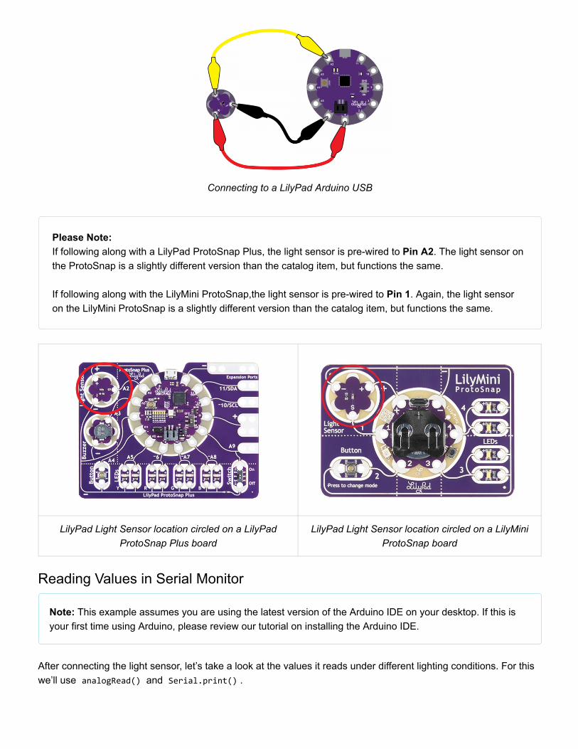
Connecting to a LilyPad Arduino USB
Please Note: If following along with a LilyPad ProtoSnap Plus, the light sensor is pre-wired to Pin A2. The light sensor onthe ProtoSnap is a slightly different version than the catalog item, but functions the same. If following along with the LilyMini ProtoSnap,the light sensor is pre-wired to Pin 1. Again, the light sensoron the LilyMini ProtoSnap is a slightly different version than the catalog item, but functions the same.
LilyPad Light Sensor location circled on a LilyPadProtoSnap Plus board
LilyPad Light Sensor location circled on a LilyMiniProtoSnap board
Reading Values in Serial Monitor
Note: This example assumes you are using the latest version of the Arduino IDE on your desktop. If this isyour first time using Arduino, please review our tutorial on installing the Arduino IDE.
After connecting the light sensor, let’s take a look at the values it reads under different lighting conditions. For thiswe’ll use analogRead() and Serial.print() .

Upload the following code to your LilyPad Arduino, making sure to select the correct LilyPad board from theTools->Board drop down menu. Choose LilyPad Arduino USB if using a LilyPad Arduino USB. The LilyPadArduino Simple, LilyPad Arduino, LilyPad Development Board, and Development Board Simple all use aLilyPad ATmega 328. Select LilyPad USB Plus if following along with the LilyPad USB Plus or LilyPadProtoSnap Plus. Don't forget to select the Serial Port that your LilyPad is connected to. Note the following potential code changes:
If prototyping with a LilyPad ProtoSnap Plus, change sensorPin to A2.If prototyping with a LilyMini ProtoSnap, change sensorPin to 1.
Copy the following code and upload it to your LilyPad.
/****************************************************************************** LilyPad Light Sensor Example SparkFun Electronics This example code reads the input from a LilyPad Light Sensor and displays in the Serial Monitor. Light Sensor connections: * S tab to A2 * + tab to + * - tab to - ******************************************************************************/ // Set which pin the Signal output from the light sensor is connected to int sensorPin = A2; // Create a variable to hold the light reading int lightValue; void setup() { // Set sensorPin as an INPUT pinMode(sensorPin, INPUT); // Initialize Serial, set the baud rate to 9600 bps. Serial.begin(9600); } void loop() { // Get the current light level lightValue = analogRead(sensorPin); // Print some descriptive text and then the value from the sensor Serial.print("Light value is:"); Serial.println(lightValue); // Delay so that the text doesn't scroll too fast on the Serial Monitor. // Adjust to a larger number for a slower scroll. delay(200); }
Once your code is uploaded, open the serial terminal in the IDE and observe the output. Numbers should begin tostream by. Note how the numbers change as the ambient light changes. Use your hand to cover the sensor or aflashlight to shine more light on it. Next we’ll be using these values to control behaviors in our code.
Using Values to Trigger BehaviorsNext, we’ll make some decisions in the code based on the light sensor’s readings. This example code creates asimple automatic night light that turns on an LED when it’s dark.

We’ll use the analogRead() function to get data from the light sensor and compare it to a variable we set fordarkness level. When the readings from the light sensor fall below our threshold set for dark, it will turn on theLED.
You can hook up a LilyPad LED to sew tab 5 or use the built-in LED attached to pin 13.
/****************************************************************************** LilyPad Light Sensor Trigger - Automatic Night Light SparkFun Electronics Adapted from Digital Sandbox Experiment 11: Automatic Night Light This example code reads the input from a LilyPad Light Sensor compares it to a set threshold named 'dark'. If the light reading is below the threshold, an LED will turn on. Light Sensor connections: * S tab to A2 * + tab to + * - to - Connect an LED to pin 5 or use the built-in LED on pin 13 ******************************************************************************/ // The dark variable determines when we turn the LEDs on or off. // Set higher or lower to adjust sensitivity. const int darkLevel = 50; // Create a variable to hold the readings from the light sensor. int lightValue; // Set which pin the Signal output from the light sensor is connected to int sensorPin = A2; // Set which pin the LED is connected to. // Set to 5 if you'd rather hook up your own LED to the LilyPad Arduino. int ledPin = 13; void setup() { // Set sensorPin as an INPUT pinMode(sensorPin, INPUT); // Set LED as outputs pinMode(ledPin, OUTPUT); // Initialize Serial, set the baud rate to 9600 bps. Serial.begin(9600); } void loop() { // Read the light sensor's value and store in 'lightValue' lightValue = analogRead(sensorPin); // Print some descriptive text and then the value from the sensor Serial.print("Light value is:"); Serial.println(lightValue);
// Compare "lightValue" to the "dark" variable if (lightValue <= darkLevel) // If the reading is less then 'darkLevel' { digitalWrite(ledPin, HIGH); // Turn on LED } else // Otherwise, if "lightValue" is greater than "dark" { digitalWrite(ledPin, LOW); // Turn off LED } // Delay so that the text doesn't scroll to fast on the Serial Monitor. // Adjust to a larger number for a slower scroll. delay(100); }
If your light sensor isn’t triggering correctly, check the output of the Serial Monitor to see if there’s a better value forthe dark variable than what is set in the example code.
Sewing into a ProjectOnce you are finished prototyping your project using the LilyPad Light Sensor, you can replace any temporaryconnections with conductive thread.
For an overview of sewing with conductive thread, check out this guide:
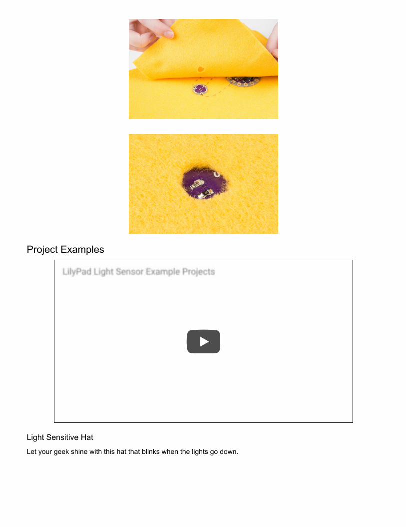
To hide the sensor in your project, you can cover with a material making sure to leave an opening for the sensor tobe exposed to light. Cutting a hole above the sensor in fabric is one way to do this.
LilyPad Basics: E-SewingDECEMBER 17, 2016Learn how to use conductive thread with LilyPad components.
Project Examples
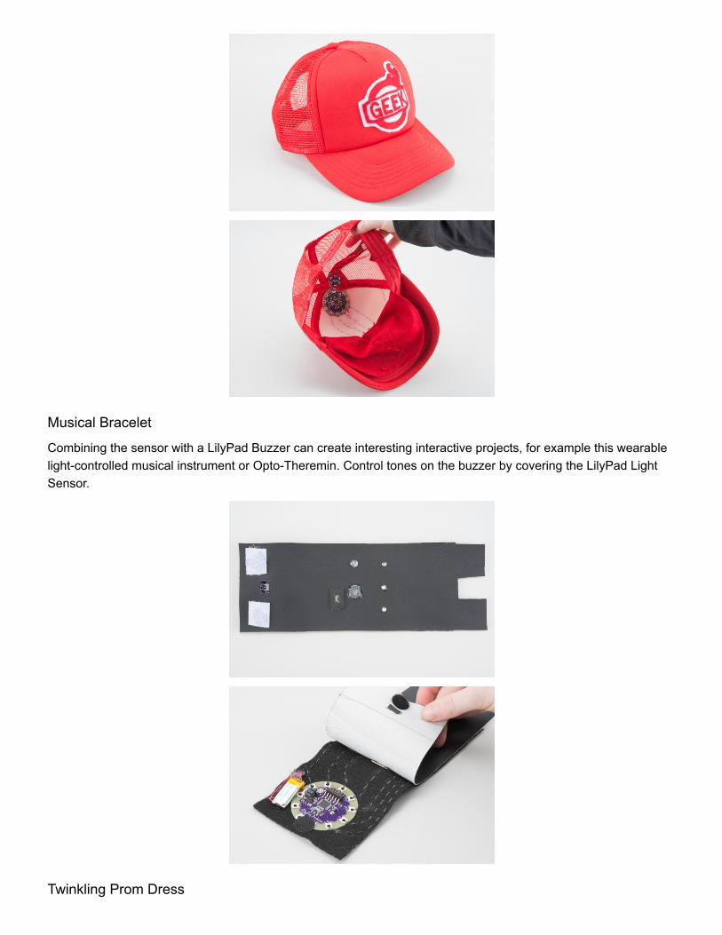
Light Sensitive Hat
Let your geek shine with this hat that blinks when the lights go down.
LilyPad Light Sensor Example Projects
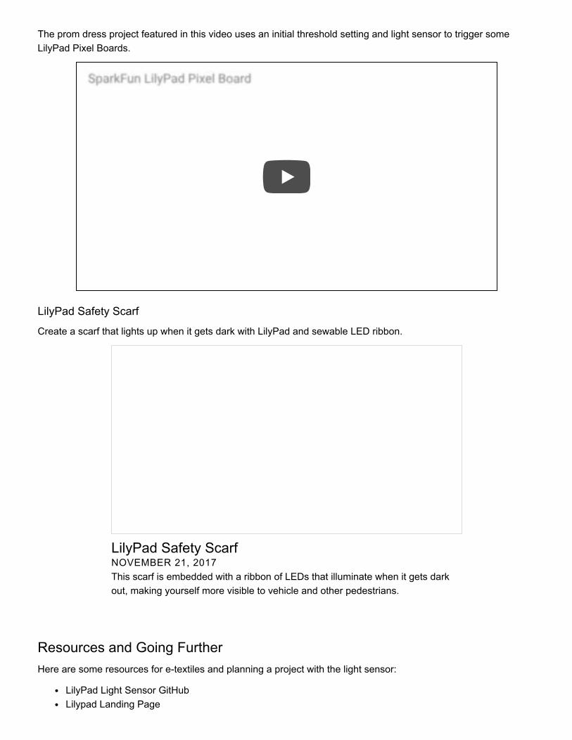
Musical Bracelet
Combining the sensor with a LilyPad Buzzer can create interesting interactive projects, for example this wearablelight-controlled musical instrument or Opto-Theremin. Control tones on the buzzer by covering the LilyPad LightSensor.
Twinkling Prom Dress
The prom dress project featured in this video uses an initial threshold setting and light sensor to trigger someLilyPad Pixel Boards.
LilyPad Safety Scarf
Create a scarf that lights up when it gets dark with LilyPad and sewable LED ribbon.
Resources and Going FurtherHere are some resources for e-textiles and planning a project with the light sensor:
LilyPad Light Sensor GitHubLilypad Landing Page
SparkFun LilyPad Pixel Board
LilyPad Safety ScarfNOVEMBER 21, 2017This scarf is embedded with a ribbon of LEDs that illuminate when it gets darkout, making yourself more visible to vehicle and other pedestrians.

Planning a Wearable Electronics ProjectInsulation Techniques for e-TextilesMakerspace for Education with LilyPad
Or, you can check out these other great light-based tutorials:
Bubble Display Hookup GuideNeed a small, cheap, and easy display? These bubbledisplays are what you've been looking for. Learn how touse them in this hookup guide.
LilyPad Light Sensor Hookup GuideHow to hook up the LilyPad Light Sensor as well assome project ideas and example code.
Building a Safe Cracking RobotHow to crack an unknown safe in under an hour.
LilyPad Tri-Color LED Hookup GuideLearn how to hook up the LilyPad Tri-Color LED anduse a common cathode RGB LED in e-textile projects.