limit analysis applied to masonry arch bridges: state-of-the · pdf file ·...
TRANSCRIPT

1 INTRODUCTION
It was pointed out by Kooharian (1952), Heyman (1966) and others that plastic theory formu-lated initially for steel structures could be applied to masonry gravity structures such as arch bridges provided certain assumptions were made. An underlying premise was that masonry can conceptually be considered as possessing a ‘ductile’ moment capacity, albeit one which is pri-marily a function of the arch thickness and normal force at a cross-section.
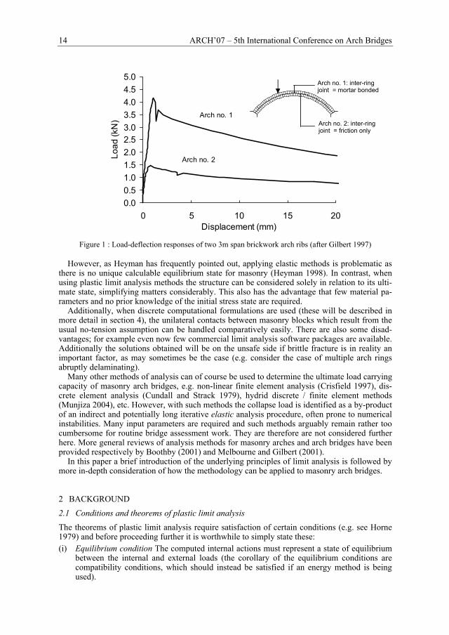
Experimental evidence largely supports this standpoint. For example Fig. 1 shows the load vs. deflection responses of two bare masonry arch ribs of differing construction tested to col-lapse in the laboratory. Using terminology borrowed from the field of steel structures, in both cases it is evident that the overall response is reasonably ‘ductile’ (in that the fall off in capacity is relatively modest providing displacements are small). The contribution of inter-ring friction to the resistance in the case of arch no. 2 increases this apparent ‘ductility’. Similarly when soil filling is present the response generally becomes yet more ‘ductile’, as increasing mobilized soil strength acts to counteract the damaging effects of gross displacements. Thus Heyman strongly argued that plastic theory should also be applied to the analysis of masonry structures, including masonry arch bridges specifically (Heyman 1980). To perform an analysis he simplified the problem by assuming that:
(i) the masonry in the arch has no tensile strength; (ii) the masonry in the arch is incompressible; (iii) sliding between masonry units cannot occur.
Although Heyman’s methodology was not dissimilar to that used by workers such as Coulomb centuries earlier (Heyman 1972), at the time this marked a fundamental shift in approach. For example, although Pippard (1951) had performed load tests to collapse on laboratory bridges, and had analyzed these using what we would now regard as a plastic ‘mechanism analysis’ ap-proach, he was personally committed to the permissible stress elastic analysis philosophy which prevailed at the time (the well known MEXE method of assessment for masonry arch bridges stemmed from Pippard’s study of the elastic response of a 2-pinned parabolic arch).
Limit analysis applied to masonry arch bridges: state-of-the-art and recent developments
M. Gilbert University of Sheffield, Department of Civil & Structural Engineering, Sheffield, UK.
ABSTRACT: Limit analysis potentially provides a highly effective means of verifying the safety of structures and has successfully been applied to masonry arch bridges for many years. Hand based limit analysis techniques have been largely superseded by computer based methods which are the primary focus of this paper. Recent developments to ‘thrust line’, discrete ‘rigid block’ and various combined soil-arch interaction limit analysis models for masonry arch bridges are discussed and areas where further work is required are identified.
14 ARCH’07 – 5th International Conference on Arch Bridges
0.00.51.01.52.02.53.03.54.04.55.0
0 5 10 15 20Displacement (mm)
Load
(kN
) Arch no. 1
Arch no. 2
Figure 1 : Load-deflection responses of two 3m span brickwork arch ribs (after Gilbert 1997)
However, as Heyman has frequently pointed out, applying elastic methods is problematic as
there is no unique calculable equilibrium state for masonry (Heyman 1998). In contrast, when using plastic limit analysis methods the structure can be considered solely in relation to its ulti-mate state, simplifying matters considerably. This also has the advantage that few material pa-rameters and no prior knowledge of the initial stress state are required.
Additionally, when discrete computational formulations are used (these will be described in more detail in section 4), the unilateral contacts between masonry blocks which result from the usual no-tension assumption can be handled comparatively easily. There are also some disad-vantages; for example even now few commercial limit analysis software packages are available. Additionally the solutions obtained will be on the unsafe side if brittle fracture is in reality an important factor, as may sometimes be the case (e.g. consider the case of multiple arch rings abruptly delaminating).
Many other methods of analysis can of course be used to determine the ultimate load carrying capacity of masonry arch bridges, e.g. non-linear finite element analysis (Crisfield 1997), dis-crete element analysis (Cundall and Strack 1979), hydrid discrete / finite element methods (Munjiza 2004), etc. However, with such methods the collapse load is identified as a by-product of an indirect and potentially long iterative elastic analysis procedure, often prone to numerical instabilities. Many input parameters are required and such methods arguably remain rather too cumbersome for routine bridge assessment work. They are therefore are not considered further here. More general reviews of analysis methods for masonry arches and arch bridges have been provided respectively by Boothby (2001) and Melbourne and Gilbert (2001).
In this paper a brief introduction of the underlying principles of limit analysis is followed by more in-depth consideration of how the methodology can be applied to masonry arch bridges.
2 BACKGROUND 2.1 Conditions and theorems of plastic limit analysis The theorems of plastic limit analysis require satisfaction of certain conditions (e.g. see Horne 1979) and before proceeding further it is worthwhile to simply state these: (i) Equilibrium condition The computed internal actions must represent a state of equilibrium
between the internal and external loads (the corollary of the equilibrium conditions are compatibility conditions, which should instead be satisfied if an energy method is being used).
Arch no. 1: inter-ring joint = mortar bonded
Arch no. 2: inter-ring joint = friction only
M. Gilbert 15
(ii) Mechanism condition Sufficient releases must be made to transform the structure into a mechanism.
(iii) Yield condition. The stresses in the material must be everywhere less than or equal to the material strength (e.g. shear, crushing and tensile strength limits must all be respected).
Now consider a structure subject to an applied load which is multiplied by a load factor λ. The three fundamental theorems of plastic analysis can now be stated in simplified form as: (i) Static or lower bound theorem If at any load factor λ the equilibrium and yield conditions
are everywhere satisfied, then λ = λl which is less than or equal to the failure load factor λp. (ii) Kinematic or upper bound theorem If at any load factor λ is equal to the work done in
plastic energy dissipation, then λ = λu which is greater than or equal to the failure load fac-tor λp.
(iii) Uniqueness theorem If at any load factor λ, the internal stress state is such that the three conditions of equilibrium, mechanism, and yield are satisfied then that load factor is the collapse load factor λp.
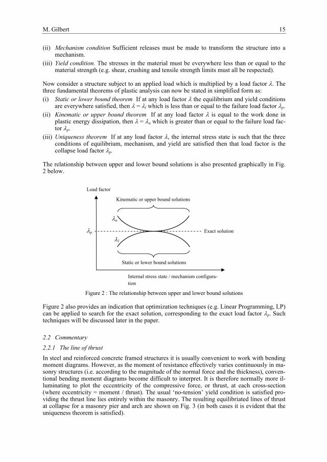
The relationship between upper and lower bound solutions is also presented graphically in Fig. 2 below.
Figure 2 : The relationship between upper and lower bound solutions
Figure 2 also provides an indication that optimization techniques (e.g. Linear Programming, LP) can be applied to search for the exact solution, corresponding to the exact load factor λp. Such techniques will be discussed later in the paper.
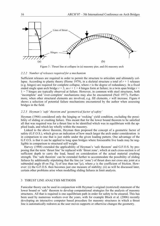
2.2 Commentary 2.2.1 The line of thrust In steel and reinforced concrete framed structures it is usually convenient to work with bending moment diagrams. However, as the moment of resistance effectively varies continuously in ma-sonry structures (i.e. according to the magnitude of the normal force and the thickness), conven-tional bending moment diagrams become difficult to interpret. It is therefore normally more il-luminating to plot the eccentricity of the compressive force, or thrust, at each cross-section (where eccentricity = moment / thrust). The usual ‘no-tension’ yield condition is satisfied pro-viding the thrust line lies entirely within the masonry. The resulting equilibriated lines of thrust at collapse for a masonry pier and arch are shown on Fig. 3 (in both cases it is evident that the uniqueness theorem is satisfied).
λp
λu
λl Exact solution
Kinematic or upper bound solutions
Static or lower bound solutions
Load factor
Internal stress state / mechanism configura-tion
16 ARCH’07 – 5th International Conference on Arch Bridges
(a) (b)
Figure 3 : Thrust line at collapse in (a) masonry pier, and (b) masonry arch
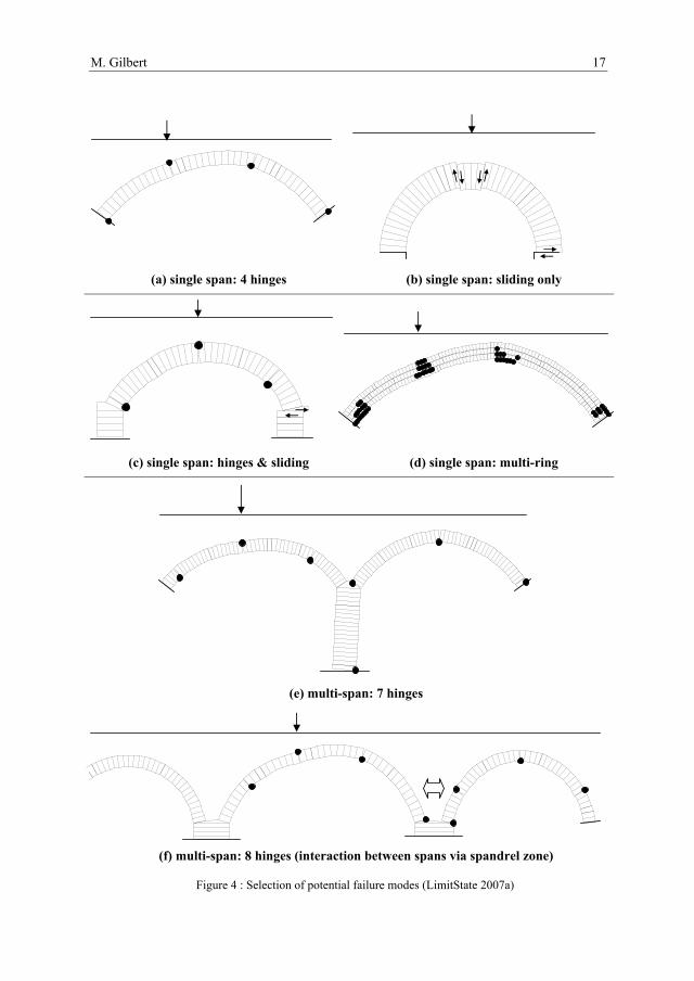
2.2.2 Number of releases required for a mechanism Sufficient releases are required in order to permit the structure to articulate and ultimately col-lapse. According to plastic theory (Horne 1979), in a skeletal structure a total of r + 1 releases (e.g. hinges) are required for complete collapse, where r is the degree of redundancy. In a fixed ended single span arch bridge r = 3, so r + 1 = 4 hinges form at failure; in a twin span bridge r + 1 = 7 hinges are typically observed at failure. However, in common with steel structures, both ‘incomplete’ and ‘over-complete’ mechanisms may also be encountered (Neil 1977). Further-more, when other structural elements are involved, e.g. fill elements, r will increase. Figure 4 shows a selection of potential failure mechanisms encountered by the author when assessing bridges in the field.
2.2.3 Heyman’s ‘safe’ theorem and ‘geometrical factor of safety’ Heyman (1966) considered only the hinging or ‘rocking’ yield condition, excluding the possi-bility of sliding or crushing failure. This meant that for the lower bound theorem to be satisfied all that was required was for a thrust line to be identified which was in equilibrium with the ap-plied loads, and which lay wholly within the masonry.
Linked to the above theorem, Heyman then proposed the concept of a geometric factor of safety (G.F.O.S.), which gives an indication of how much larger the arch under consideration is in comparison to one that is just stable under the given loading pattern. One advantage of the G.F.O.S. is that it can be applied to long span bridges where foreseeable live loads may be neg-ligible in comparison to structural self weight.
Harvey (1988) extended the applicability of Heyman’s ‘safe theorem’ and G.F.O.S. by pro-posing that the term ‘thrust line’ be replaced with ‘thrust zone’, which at each cross-section is of sufficient depth to carry the load, based on consideration of the actual material crushing strength. The ‘safe theorem’ can be extended further to accommodate the possibility of sliding failures by additionally stipulating that the line (or ‘zone’) of thrust does not cross any joint at a subtended angle (θ on Fig. 3) of less than tan-1(µ), where µ is the coefficient of friction. How-ever: (i) the G.F.O.S. then becomes just one measure of stability; (ii) as will be discussed later, certain other problems arise when modelling sliding failures in limit analysis.
3 THRUST LINE ANALYSIS METHODS
Funicular theory can be used in conjunction with Heyman’s original (restricted) statement of the lower bound or ‘safe’ theorem to develop computational strategies for the analysis of masonry structures. All that is required is one equilibrium path in order for safety to be ensured. This has been used by numerous workers over the years, with for example Block et al. (2006) recently developing an interactive computer based procedure for masonry structures in which a thrust line is automatically redrawn as the user moves supports or otherwise changes the geometry.
θ Lines of thrust
Hinges
M. Gilbert 17
(a) single span: 4 hinges (b) single span: sliding only
(c) single span: hinges & sliding (d) single span: multi-ring
(e) multi-span: 7 hinges
(f) multi-span: 8 hinges (interaction between spans via spandrel zone)
Figure 4 : Selection of potential failure modes (LimitState 2007a)

18 ARCH’07 – 5th International Conference on Arch Bridges
Also using this philosophy O’Dwyer (1999) proposed a force network model to analyze 3D masonry structures. His procedure involves proposing an initial network of bars to transmit the self weight and imposed loads to the supports and then using linear programming (LP) to move joints vertically to ensure all bars, still in equilibrium, can be fitted entirely within the body of the masonry, thus ensuring compliance of Heyman’s original statement of the safe theorem. In a similar vein a little explored alternative approach is to apply truss layout optimization methods. In this case a permissible design domain is setup which corresponds to the volume of masonry in the vault, barrel or bridge under consideration. The domain is then populated with nodes and potential inter-connecting bars. LP is then used to identify an arrangement of bars which satis-fies equilibrium. A potential advantage of this method is that an initial layout of bars does not need to be manually specified at the start of the process. A simple example of a generated layout is shown on Fig. 5 (Gilbert et al. 2005), though in this case for simplicity a uniform vertical load was specified, rather than the load imparted by a real vault.
Figure 5 : Potential force paths for a masonry vault identified using layout optimization At present only a limited range of yield conditions are typically considered using analyses of this sort (sliding and 3D torsional failure modes are not usually considered). The exclusion of certain potential failure modes does mean that the solutions obtained are not necessarily safe.
4 DISCRETE LIMIT ANALYSIS MODELS
4.1 Background Whilst the masonry forming the arch barrel, piers and abutments of a bridge can be modelled using continuum analysis methods, the fact that the joints form natural predefined planes of weakness makes discrete analysis methods particularly attractive; such methods are therefore now considered here.
Although little known until the 1990s, in the 1970s Livesley (1978) pioneered the develop-ment of discrete limit analysis models for masonry structures. In a discrete model the masonry forming an arch bridge is idealized using a series of rigid blocks, typically geometrically slightly larger than the physical blocks to account for the fact that mortar joints (if present) are not usually explicitly modelled. Using this approach arbitrary assemblages of blocks can be ana-lyzed, including single and multi-span masonry arch bridges. To save computational effort ‘macroblocks’ which are significantly larger than the physical units can also be used, although in this case care must be taken to ensure that such a discretization does not significantly affect the predicted mode of response.
The problem may be posed in either equilibrium or kinematic (work) form, and then can in many cases be solved using linear programming (LP). However, LP duality theory (Charnes et al., 1959) dictates that the predicted collapse loads will be identical whichever form is used (i.e. as indicated graphically in Fig. 2). Furthermore the solution to the other will become available
M. Gilbert 19
once the problem is solved (e.g. if the equilibrium form is formulated, the displacements and hinge rotations will become available), and both forms will produce the exact load factor λp for a given discretization of blocks.
Various alternative LP formulations can be posed, two of which were recently compared by Ahmed and Gilbert (2003). Modern so-called ‘interior point’ linear programming solvers (Van-derbei, 2001) are capable of solving very large-scale problems, and are gradually supplanting solvers based on the long established ‘Simplex’ method. A joint equilibrium formulation, simi-lar to that proposed initially by Livesley (1978), which can be solved very efficiently using modern interior point Linear Programming (LP) algorithms is presented below.
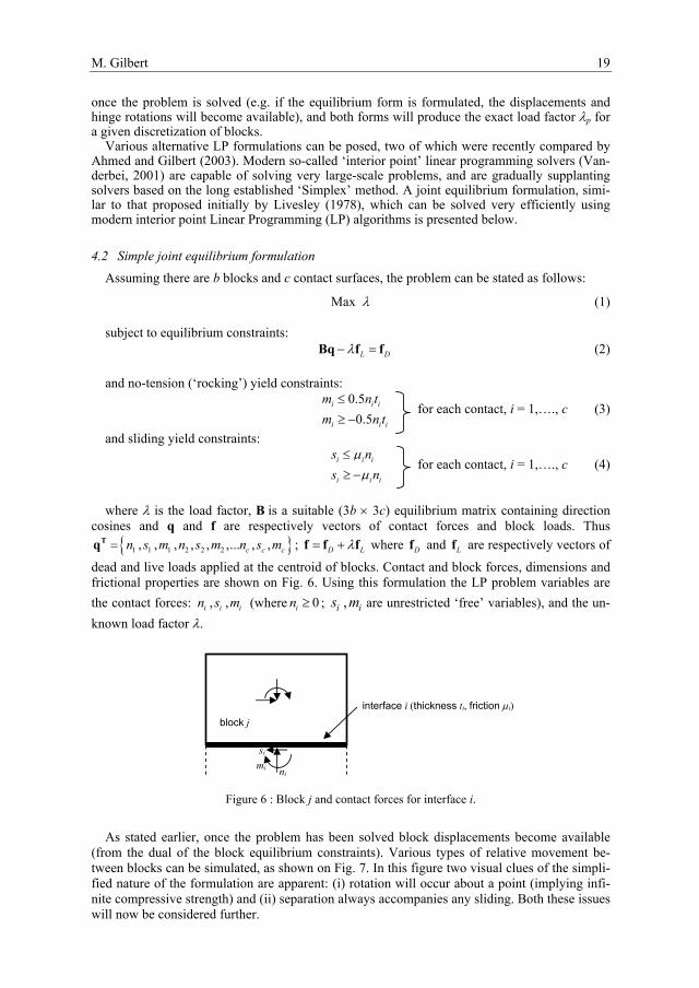
4.2 Simple joint equilibrium formulation Assuming there are b blocks and c contact surfaces, the problem can be stated as follows:
Max λ (1)
subject to equilibrium constraints: L Dλ− =Bq f f (2)
and no-tension (‘rocking’) yield constraints: 0.5
0.5i i i
i i i
m n tm n t
≤≥ −
for each contact, i = 1,…., c (3)
and sliding yield constraints: i i i
i i i
s ns n
µµ
≤≥ −
for each contact, i = 1,…., c (4)
where λ is the load factor, B is a suitable (3b × 3c) equilibrium matrix containing direction
cosines and q and f are respectively vectors of contact forces and block loads. Thus { }1 1 1 2 2 2, , , , , ,... , ,c c cn s m n s m n s m=Tq ; D Lλ= +f f f where Df and Lf are respectively vectors of
dead and live loads applied at the centroid of blocks. Contact and block forces, dimensions and frictional properties are shown on Fig. 6. Using this formulation the LP problem variables are the contact forces: , ,i i in s m (where 0in ≥ ; ,i is m are unrestricted ‘free’ variables), and the un-known load factor λ.
Figure 6 : Block j and contact forces for interface i.
As stated earlier, once the problem has been solved block displacements become available
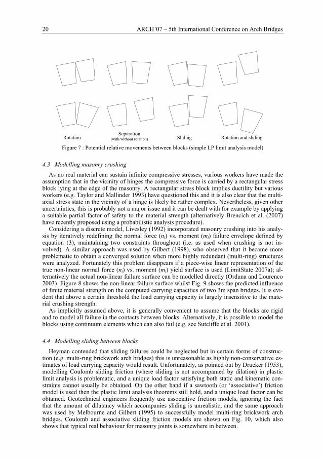
(from the dual of the block equilibrium constraints). Various types of relative movement be-tween blocks can be simulated, as shown on Fig. 7. In this figure two visual clues of the simpli-fied nature of the formulation are apparent: (i) rotation will occur about a point (implying infi-nite compressive strength) and (ii) separation always accompanies any sliding. Both these issues will now be considered further.
block j
mi ni
si
interface i (thickness ti, friction µi)
20 ARCH’07 – 5th International Conference on Arch Bridges
Rotation Separation
(with/without rotation) Sliding Rotation and sliding
Figure 7 : Potential relative movements between blocks (simple LP limit analysis model)
4.3 Modelling masonry crushing As no real material can sustain infinite compressive stresses, various workers have made the
assumption that in the vicinity of hinges the compressive force is carried by a rectangular stress block lying at the edge of the masonry. A rectangular stress block implies ductility but various workers (e.g. Taylor and Mallinder 1993) have questioned this and it is also clear that the multi-axial stress state in the vicinity of a hinge is likely be rather complex. Nevertheless, given other uncertainties, this is probably not a major issue and it can be dealt with for example by applying a suitable partial factor of safety to the material strength (alternatively Brencich et al. (2007) have recently proposed using a probabilistic analysis procedure).
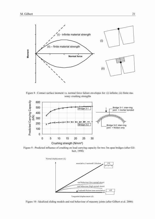
Considering a discrete model, Livesley (1992) incorporated masonry crushing into his analy-sis by iteratively redefining the normal force (ni) vs. moment (mi) failure envelope defined by equation (3), maintaining two constraints throughout (i.e. as used when crushing is not in-volved). A similar approach was used by Gilbert (1998), who observed that it became more problematic to obtain a converged solution when more highly redundant (multi-ring) structures were analyzed. Fortunately this problem disappears if a piece-wise linear representation of the true non-linear normal force (ni) vs. moment (mi) yield surface is used (LimitState 2007a); al-ternatively the actual non-linear failure surface can be modelled directly (Orduna and Lourenco 2003). Figure 8 shows the non-linear failure surface whilst Fig. 9 shows the predicted influence of finite material strength on the computed carrying capacities of two 3m span bridges. It is evi-dent that above a certain threshold the load carrying capacity is largely insensitive to the mate-rial crushing strength.
As implicitly assumed above, it is generally convenient to assume that the blocks are rigid and to model all failure in the contacts between blocks. Alternatively, it is possible to model the blocks using continuum elements which can also fail (e.g. see Sutcliffe et al. 2001).
4.4 Modelling sliding between blocks Heyman contended that sliding failures could be neglected but in certain forms of construc-
tion (e.g. multi-ring brickwork arch bridges) this is unreasonable as highly non-conservative es-timates of load carrying capacity would result. Unfortunately, as pointed out by Drucker (1953), modelling Coulomb sliding friction (where sliding is not accompanied by dilation) in plastic limit analysis is problematic, and a unique load factor satisfying both static and kinematic con-straints cannot usually be obtained. On the other hand if a sawtooth (or ‘associative’) friction model is used then the plastic limit analysis theorems still hold, and a unique load factor can be obtained. Geotechnical engineers frequently use associative friction models, ignoring the fact that the amount of dilatancy which accompanies sliding is unrealistic, and the same approach was used by Melbourne and Gilbert (1995) to successfully model multi-ring brickwork arch bridges. Coulomb and associative sliding friction models are shown on Fig. 10, which also shows that typical real behaviour for masonry joints is somewhere in between.
M. Gilbert 21
-30
-20
-10
0
10
20
30
0 7.25 14.5 21.75 29Normal forceMom
ent
Figure 8 : Contact surface moment vs. normal force failure envelopes for: (i) infinite; (ii) finite ma-sonry crushing strengths
0
100
200
300
400
500
600
0 5 10 15 20 25 30
Crushing strength (N/mm²)
Pre
dict
ed C
arry
ing
Cap
acity
(kN
)
Bridge 3-2
Bridge 3-1
Figure 9 : Predicted influence of crushing on load carrying capacity for two 3m span bridges (after Gil-
bert, 1998)
Coulomb friction (non-associative)
associative (‘sawtooth’) friction
Tangential displacement (δt)
real behaviour (low normal stress)
real behaviour (high normal stress)
Normal displacement (δn)
Figure 10 : Idealized sliding models and real behaviour of masonry joints (after Gilbert et al. 2006)
(i) - infinite material strength
(ii)
(i)
(ii) – finite material strength
Bridge 3-2: inter-ring joint = friction only
Bridge 3-1: inter-ring joint = mortar bonded

22 ARCH’07 – 5th International Conference on Arch Bridges
The problem of modelling sliding was also identified by Livesley (1978), who noted that a joint equilibrium formulation of the type presented in section 4.2 corresponds to a kinematic formu-lation incorporating an associative friction model. Subsequently workers such as Ferris and Tin Loi (2001) and Orduna and Lourenco (2003) proposed ways in which an estimate of the load factor could nevertheless be obtained. Whilst these workers used non-linear programming (NLP) formulations, Gilbert et al. (2006) instead proposed a simpler solution procedure requir-ing successive application of LP. Applying this procedure to multi-ring brickwork arch bridges analyzed previously with an associative friction model, Gilbert and Ahmed (2004) found that the non-associative bridge strength predictions were at most 6 percent lower, largely justifying the initial associative friction idealization.
In 3D analysis the sliding problem becomes potentially more important. This has been con-sidered by Livesley (1992), Baggio and Trovalusci (1998) and Orduna and Lourenco (2005a, b). The latter authors derived yield criteria for torsional sliding failure mechanisms and observed that, when Coulomb friction is involved, obtaining the minimum load factor may not lead to a realistic solution being obtained (the solution obtained may be unrealistically low). An alterna-tive load path following procedure was therefore proposed.
4.5 Introducing reinforcement The introduction of reinforcement has the potential to significantly alter the mode of response. Whilst purists may argue that masonry arch bridges should always remain unreinforced, rein-forcement has been incorporated in bridges at least since Roman times, and subsequently in structures ranging from the Old Bridge in Mostar, Bosnia-Herzegovina to Isambard Kingdom Brunel’s imposing Maidenhead Bridge across the Thames in the UK.
Reinforcement has been incorporated in plastic limit analysis models by workers such as Or-duna and Lourenco (2003), Lourenco et al. (2004) and Chen et al. (2007). The main concern is that the addition of reinforcement may trigger undesirable brittle failure modes (analogous to over-reinforcing conventional reinforced concrete beams). For example including near-surface reinforcement in a multi-ring brickwork arch may increase the likelihood of ring separation (de-lamination).
A further issue is one of design: if bridge strength is inadequate, where should additional re-inforcement be placed? To address this, the plastic layout optimization techniques referred to earlier could potentially be used. Figure 11 shows a simple example problem which illustrates the principle; the arch shown is unable to carry the specified load and optimization has been used to find minimum weight layouts of supplementary truss bars to allow the load to be car-ried. Rather more practical strengthening strategies are currently being investigated, for exam-ple identifying the optimal location of reinforcing elements placed in the soil surrounding an arch barrel.
5 SOIL ARCH INTERACTION 5.1 Simplified analysis – indirect modelling of load spreading and passive restraint
As masonry arch bridges have traditionally been analyzed by structural engineers it is per-haps understandable that the influence of the soil surrounding the arch barrels of most bridges has been given scant attention. However, whilst Heyman (1980) chose to neglect the beneficial effect of live load spreading through the fill and of passive fill restraint, subsequent workers have made some attempt to include them. A variety of semi-empirical load spreading models have been adopted (e.g. assuming uniform, sinusoidal or Boussinesq distributions); to the au-thor’s knowledge a distribution model derived using formal plasticity theory has to date not been used. Classical vertical retaining wall theory has frequently been used to model the passive restraint provided by the soil (resisting sway of the arch into the fill); for frictional fill materials it has typically been found that a factor of approximately 1/3 applied to the classical earth pres-sure coefficient provides reasonable agreement with observed test results when four hinge fail-ures are involved. These idealizations have little theoretical justification. To ensure that soil pressures are mobilized in the correct (i.e. passive) sense, instead of applying pressures directly to the arch, uniaxial line elements can be employed, e.g. as incorporated in the ring software

M. Gilbert 23
(Gilbert 2001). Such a model was recently successfully used to show that the load carrying ca-pacity of masonry arch bridges will be significantly affected if the arch and fill are submerged by flood water (Hulet et al. 2006).
(a) (Over)loaded arch and design domain
(b) Optimal layout of strengthening elements
(c) Revised layout with rectangular prohibited zone
(d) Revised layout with trapezoidal prohibited zone
Figure 11 : Illustration of the use of layout optimization to identify the optimal locations of strength-ening elements in an under-strength arch
5.2 Full modelling of soil and arch 5.2.1 Finite element limit analysis To provide an arguably more rational representation of the soil-arch system, Cavicchi and Gambarotta (2005) presented a finite element limit analysis model in which the fill was mod-elled using 3-noded constant strain finite elements. Apart from details of the mesh geometry, in finite element limit analysis the only required input parameters are the soil cohesion and angle of friction. This is attractive as unlike elasto-plastic finite elements, details of the initial stress state, elastic modulus etc. are not required, greatly simplifying matters. Furthermore, solutions have definite status (i.e. upper or lower bounds on the ‘exact’ solution) and can be obtained us-ing robust mathematical programming solvers rather than by using potentially unreliable incre-mental solvers. Cavicchi and Gambarotta also scrutinized the influence of making the plane strain assumption, which is potentially inappropriate in the case of a narrow bridge.
Elsewhere in the present proceedings, Gilbert et al. (2007) describe the use of finite element limit analysis to analyze a laboratory bridge tested under carefully controlled conditions. Using upper and lower-bound formulations, it was found that reasonably close bounds on the ‘exact’ plastic collapse load could be obtained (linear strain elements were used to obtain accurate up-per-bound predictions). However it was found that if the measured peak material strengths (i.e. soil cohesion and angle of friction) were used in the model, significant overestimates of bridge carrying capacity were obtained. In reality soil strength is only mobilized by large movements, which conversely have a detrimental effect on structural strength. This is an important issue which must be borne in mind before such models are used in practice. An additional issue, sometimes glossed over in the literature, is the importance of mesh geometry, Carefully tailored meshes generally need to be used in order to obtain good lower and upper bound predictions (e.g. note the high mesh refinement under the load in Fig. 12).
24 ARCH’07 – 5th International Conference on Arch Bridges
Figure 12 : Upper bound finite element limit analysis solution (after Gilbert et al. 2007)
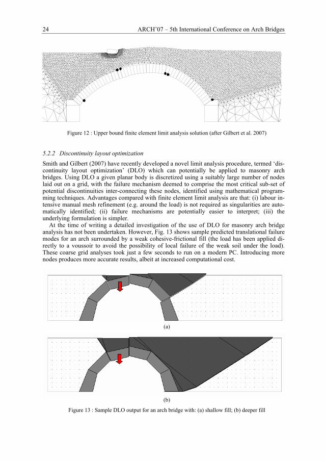
5.2.2 Discontinuity layout optimization Smith and Gilbert (2007) have recently developed a novel limit analysis procedure, termed ‘dis-continuity layout optimization’ (DLO) which can potentially be applied to masonry arch bridges. Using DLO a given planar body is discretized using a suitably large number of nodes laid out on a grid, with the failure mechanism deemed to comprise the most critical sub-set of potential discontinuities inter-connecting these nodes, identified using mathematical program-ming techniques. Advantages compared with finite element limit analysis are that: (i) labour in-tensive manual mesh refinement (e.g. around the load) is not required as singularities are auto-matically identified; (ii) failure mechanisms are potentially easier to interpret; (iii) the underlying formulation is simpler.
At the time of writing a detailed investigation of the use of DLO for masonry arch bridge analysis has not been undertaken. However, Fig. 13 shows sample predicted translational failure modes for an arch surrounded by a weak cohesive-frictional fill (the load has been applied di-rectly to a voussoir to avoid the possibility of local failure of the weak soil under the load). These coarse grid analyses took just a few seconds to run on a modern PC. Introducing more nodes produces more accurate results, albeit at increased computational cost.
(a)
(b)
Figure 13 : Sample DLO output for an arch bridge with: (a) shallow fill; (b) deeper fill

M. Gilbert 25
5.3 Gross displacement analysis As noted in the previous section (and indicated in Fig. 1), large structural movements can have a detrimental impact on the load carrying capacity of masonry arches. Conversely large move-ments are required in order to mobilize peak soil strength and hence peak passive restraint. To address this Gilbert (1997) proposed a simple coupled analysis procedure which involved updat-ing the geometry and soil pressures at successive iterations. The same issue was subsequently explored for the 4 hinge collapse mechanism case by Ng and Fairfield (2004). Additionally Ochsendorf (2006) has studied the related problem of determining the amount of abutment movement required in order to precipitate collapse of an arch, in this case without fill.
6 PRACTICAL APPLICATION OF LIMIT ANALYSIS 6.1 Available software Various specialized analysis programs which rely on the theorems of limit analysis have been developed over the years. Currently available tools include ArchieM (Obvis 2007) and ring2.0 (LimitState 2007b). ArchieM is based on a lower bound line (or ‘zone’) of thrust methodology. The program displays graphically a potential thrust-line for any given loading regime (the thrus-t-line can be manually changed if necessary). If a thrust-line cannot be found which lies entirely within the masonry then the bridge can be considered potentially unsafe. In contrast ring2.0 uses mathematical optimization to directly identify the collapse state, computing the load factor which, when applied to the specified live load, will lead to collapse. ring2.0 uses an extended version of the formulation presented in section 4.2, modelling crushing as well as sliding and also incorporating fill elements to model passive restraint.
Alternatively it is relatively easy to set up an electronic spreadsheet to solve simple masonry arch limit analysis problems, for example making use of the inbuilt ‘Solver’ function in Micro-soft Excel to identify critical hinge positions (e.g. Hughes et al., 2002).
6.2 Recent developments to existing software: support movement analysis Minor changes to the formulation outlined in section 4.2 can be made to enable support move-ments to be modelled (LimitState 2007a). Figure 14 shows the predicted response of a loaded twin-span bridge to a central support settlement modelled using ring2.0 (note also the presence of horizontal fill elements referred to in section 5.1). Vehicles can be run across the bridge to investigate load paths and to see whether the hinge positions move. If hinges move significantly in the model under moving loads, and if secondary stiffening elements such as securely attached spandrel walls are not present in reality, then this might be a cause for concern as continual opening and closing of joints may lead to incremental damage to the structure.
Figure 14 : Support movement analysis (ring2.0 screenshot, also showing hinges, zone of thrust and
horizontal fill elements)
26 ARCH’07 – 5th International Conference on Arch Bridges
6.3 Limitations of existing software: treatment of the third dimension To date readily available limit analysis software has been two-dimensional. Consequently
when such software is applied to real, three-dimensional, bridges, certain assumptions have to be made about the third dimension. Standard practice to date has been to assume that an applied load will mobilize a fixed-width strip of the bridge. For narrow bridges this may be reasonable but Harvey et al. (2005) have recently proposed an interesting ‘fan distribution’ model to simu-late the dispersal of an applied load through the arch barrels of wider bridges. Further validation work is however required before this model can be recommended for use in practice.
7 CONCLUSIONS
Limit analysis provides a conceptually simple and robust means of analyzing the ultimate col-lapse state of masonry arch bridges. Advances in computer processing power and the emergence of highly efficient mathematical programming solvers allow results to be obtained rapidly, and with a limited set of input data. This makes computational limit analysis eminently suitable for use in routine bridge assessment work.
To date most researchers have focussed on establishing the stability of the masonry arches, piers and abutments which makeup an arch bridge. Work in this field continues, generally using either ‘line of thrust’ or discrete ‘rigid block’ type analysis procedures. However the important strengthening role played by the backfill has led to the recent development of some interesting computational strategies which allow explicit modelling of both masonry and soil components. Work in this area is ongoing.
To date relatively little attention has been paid to the third dimension, partly because of the relatively high computational expense associated with fully 3D analysis models and partly be-cause of theoretical problems associated with modelling Coulomb sliding friction. It can be ex-pected that activity in this research area will intensify in the coming years.
ACKNOWLEDGEMENTS
The author wishes to acknowledge the current support of the UK Engineering and Physical Sci-ences Research Council (EPSRC), under grant references GR/S53329/01 and GR/S53336/01, Essex County Council and the International Union of Railways (UIC). Also gratefully acknowl-edged is the assistance provided by current and previous research collaborators, in particular Colin Smith, Dong Nguyen, Wael Darwich, Husham Ahmed and Clive Melbourne.
REFERENCES
Ahmed, H.M. and Gilbert, M. 2003. The computational efficiency of two rigid block analysis formula-tions for application to masonry structures, Proc. 9th International Conference on Civil and Structural Engineering Computing, Egmond-aan-Zee, Holland, CD-ROM proceedings paper no. 104, p. 12.
Baggio, C. and Trovalusci, P. 1998. Limit analysis for no-tension and frictional three-dimensional dis-crete systems, Mech. Struct. Mach. 26(3), p. 287–304.
Block, P., Ciblac, T. and Ochsendorf, J. 2006. Real-time limit analysis of vaulted masonry buildings, Computers & Structures, 84(29-30), p. 1841-1852.
Boothby, T.E., 2001. Analysis of masonry arches and vaults. Prog. Struct. Engng. Mater. 3, p. 246-256. Brencich, A., Gambarotta, L. and Sterpi, E. 2007. Load carrying capacity of masonry arches with sto-
chastic compressive strength. Proc. 10th NAMC, St Louis, U.S.A, Paper 159. Cavicchi, A., Gambarotta, L. 2005. Collapse analysis of masonry bridges taking into account arch–fill in-
teraction. Engineering Structures. 27, p. 605-615. Charnes, A., Lemke, C.E. and Zienkiewicz, O.C. 1959. Virtual work, linear programming and plastic limit
analysis, Proc. R. Soc. A., 251. Chen, Y., Ashour A.F. and Garrity, S.W. 2007. Modified four-hinge mechanism analysis for masonry
arches strengthened with near-surface reinforcement, Engineering Structures, In Press. Crisfield, M.A. 1997, Non-linear Finite Element Analysis of Solids and Structures Volume 2: Advanced
Topics, London: Wiley.
M. Gilbert 27
Cundall, P.A. and Strack O.D.L 1979 A discrete numerical model for granular assemblies. Geotechnique, 29: p. 47–65.
Drucker, D.C. 1953. Coulomb friction, plasticity and limit loads. Trans. ASME, 76, p. 71-74. Ferris, M.C., Tin-Loi, F. 2001. Limit analysis of frictional block assemblies as a mathematical program
with complementarity constraints. International Journal of Mechanical Sciences. 43, p. 209-224. Gilbert, M. 1997. Gross displacement mechanism analysis of masonry bridges and tunnel linings. Pro-
ceedings of the 11th International Brick/Block masonry conference. Shanghai, p. 473-482. Gilbert, M. 1998. On the analysis of multi-ring brickwork arch bridges, Proc. 2nd International Arch
Bridges Conference, Venice, p. 109-118. Gilbert, M. 2001. RING: a 2D rigid-block analysis program for masonry arch bridges, in Abdunur, C.
(ed), ARCH01; Proc. 3rd International Arch Bridges Conference, Paris, p. 459-464. Gilbert, M. and Ahmed, H.M. 2004. Developments to the RING masonry arch bridge analysis software,
Proc. 4th International Arch Bridges Conference, Barcelona, p. 263-272. Gilbert, M., Darwich, W., Tyas, A., Shepherd, P. 2005. Application of large-scale layout optimization
techniques in structural engineering practice, Proc. 6th World Congress in Structural and Multidisci-plinary Optimization, Rio de Janeiro, CD-ROM proceedings.
Gilbert, M., Casapulla, C., Ahmed, H.M. 2006. Limit analysis of masonry block structures with non-associative frictional joints using linear programming. Computers and Structures. 84, p. 873-887.
Gilbert M., Nguyen D., and Smith, C.C. 2007. Computational limit analysis of soil-arch interaction in masonry arch bridges. Proc. 5th International Arch Bridges Conference, Madeira.
Harvey, W.J. 1988, The application of the mechanism method to masonry arch bridges, Struct. Engr. 66(5), p. 77-84.
Harvey, W.J., Tomor, A. and Smith, F. 2005. A three dimensional model for masonry arch bridge behav-iour, Structural Engineer International. 2/2005, p. 4-7.
Heyman, J. 1966, The stone skeleton, International Journal of Solids and Structures, 2, p. 249-279. Heyman, J. 1972, Coulomb's memoirs on statics, Cambridge: CUP. Heyman, J. 1980. The estimation of the strength of masonry arches, Proc. Instn. Civ. Eng. Part 2. 69, p.
921-937. Heyman, J. 1998. The assessment of strength of masonry arches, Proc. 2nd International Arch Bridges
Conference, Venice, p. 95-98. Horne, M.R. 1979. Plastic theory of structures, 2nd edition, Oxford: Pergamon Press. Hughes T.G., Hee S.C., Soms E. 2002. Mechanism analysis of single span masonry arch bridges using a
spreadsheet. Proceedings of the Institution of Civil Engineers; Structures and Buildings, 152 (4) p. 341-350.
Hulet, K.M, Smith, C.C., Gilbert, M. 2006. The influence of flooding on the load carrying capacity of masonry arch bridges, Proceedings of the Institution of Civil Engineers; Bridge Engineering, 159, p. 97-103
Kooharian, A. 1952. Limit analysis of voussoir (segmental) and concrete arches. Journal American Con-crete Institute, 24, p. 317-328.
LimitState Ltd. 2007a. ring2.0 theory and modelling guide. Sheffield UK. LimitState Ltd. 2007b. ring2.0 software, available from http://www.masonryarch.com. Livesley, R.K. 1978, Limit analysis of structures formed from rigid blocks. International Journal of Nu-
merical Methods in Engineering, 12, p. 1853-1871. Livesley, R.K. 1992. A computational model for the limit analysis of three-dimensional masonry struc-
tures. Meccanica 27, p. 161-172, Kluwer. Livesley, R.K. 1992, The collapse analysis of masonry arch bridges, Proc. Conf. App. Solid Mechanics 4,
Elsevier, p. 261-274. Lourenco, P.B., Palacio, K. and Barros, J.O. 2004. Design recommendations for reinforced masonry
arches. Proc. 4th International Arch Bridges Conference, Barcelona, p. 583-592. Melbourne, C. and Gilbert, M. 1995. The behaviour of multi-ring brickwork arch bridges’, The Structural
Engineer. 73(3), p. 39-47. Melbourne, C., and Gilbert, M. 2001. Modelling of masonry arch bridges, in Bull, J. (ed), Computational
modelling of masonry, brickwork and blockwork Structures, Saxe-Coburg publications, Edinburgh, p. 197-220.
Munjiza, A. 2004. The Combined Finite-discrete Element Method, John Wiley. Neil, B.G. 1977. The plastic methods of structural analysis. Chapman and Hall. London. Ng, K.H. and Fairfield C.A. 2004. Modifying the mechanism method of masonry arch bridge analysis.
Construction and Building Materials, 18, p. 91-97. Obvis Ltd. 2007. Archie-M software, available from http://www.obvis.com Ochsendorf, J. 2006. The masonry arch on spreading supports. The Structural Engineer, 84(2), p. 29-35. O’Dwyer, D. 1999, Funicular analysis of masonry vaults, Computers and Structures, 73, p. 187-197.

28 ARCH’07 – 5th International Conference on Arch Bridges
Orduna, A., Lourenco, P. 2003. Cap Model for Limit Analysis and Strengthening of Masonry Structures ASCE Journal of Structural Engineering, 129, p. 1367-1375.
Orduna, A., Lourenco, P. 2005a. Three-dimensional limit analysis of assemblages. Part I: Torsion failure on frictional interfaces and limit analysis formulation, International Journal of Solids and Structures, 42(18-19), p. 5140-5160.
Orduna, A., Lourenco, P. 2005b. Three-dimensional limit analysis of rigid blocks assemblages. Part II: Load-path following solution procedure and validation, International Journal of Solids and Structures, 42(18-19), p. 5161-5180.
Pippard, A.J.S. 1951. A study of the Voussoir arch, NBSR paper 11, HMSO. Smith, C.C. Gilbert, M. 2007 Application of discontinuity layout optimization to plane plasticity prob-
lems, Proc. R. Soc. A., in press. Sutcliffe, D. J. Yu H. S. and Page A. W. 2001. Lower bound limit analysis of unreinforced masonry shear
walls, Computers & Structures, 79(14), p. 1295-1312. Taylor, N. and Mallinder, P. 1993. The brittle hinge in masonry arch mechanisms. The Structural Engi-
neer, 71(20), p. 359-366. Vanderbei, R.J. 2001. Linear Programming: Foundations and extensions, 2nd edition, Springer.