limitorque mx - flowserve · pdf filelimitorque mx: smart multi-turn actuator that ......
TRANSCRIPT
Experience In Motion
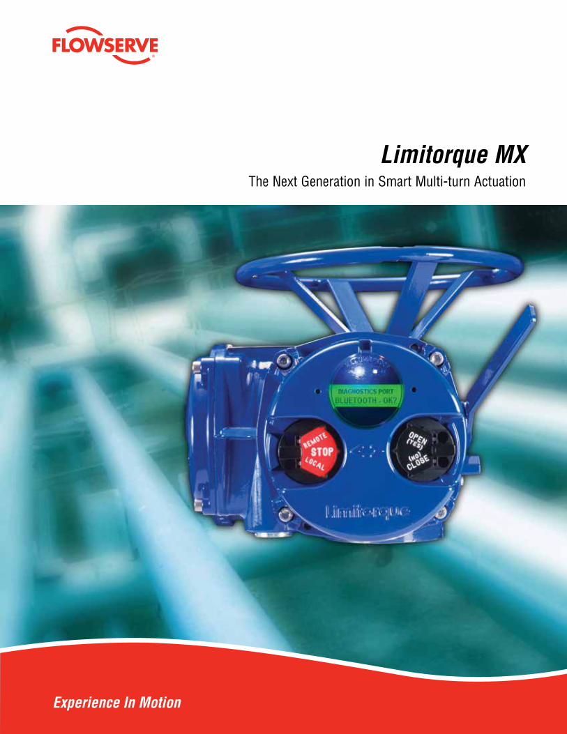
Limitorque MXThe Next Generation in Smart Multi-turn Actuation
2
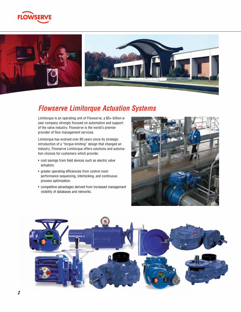
Limitorque is an operating unit of Flowserve, a $5+ billion-a-year company strongly focused on automation and support of the valve industry. Flowserve is the world’s premier provider of flow management services.
Limitorque has evolved over 80 years since its strategic introduction of a “torque-limiting” design that changed an industry. Flowserve Limitorque offers solutions and automa-tion choices for customers which provide:
• cost savings from field devices such as electric valve actuators.
• greater operating efficiencies from control room performance sequencing, interlocking, and continuous process optimization.
• competitive advantages derived from increased management visibility of databases and networks.
Flowserve Limitorque Actuation Systems
flowserve.com
3
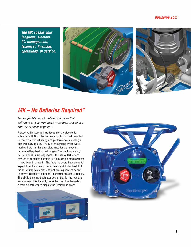
The MX speaks your language, whether it’s management, technical, financial, operations, or service.
Limitorque MX: smart multi-turn actuator that delivers what you want most — control, ease of use and “no batteries required.”
Flowserve Limitorque introduced the MX electronic actuator in 1997 as the first smart actuator that provided uncompromised reliability and performance in a design that was easy to use. The MX innovations which were market firsts – unique absolute encoder that doesn’t require battery back-up – Limigard™ technology – easy to use menus in six languages – the use of Hall effect devices to eliminate potentially troublesome reed switches – have been improved. The features Users have come to expect from Flowserve Limitorque are still standard, but the list of improvements and optional equipment permits improved reliability, functional performance and durability. The MX is the smart actuator design that is rigorous and easy to use. It is the only non-intrusive, double-sealed electronic actuator to display the Limitorque brand.
MX – No Batteries Required”
4
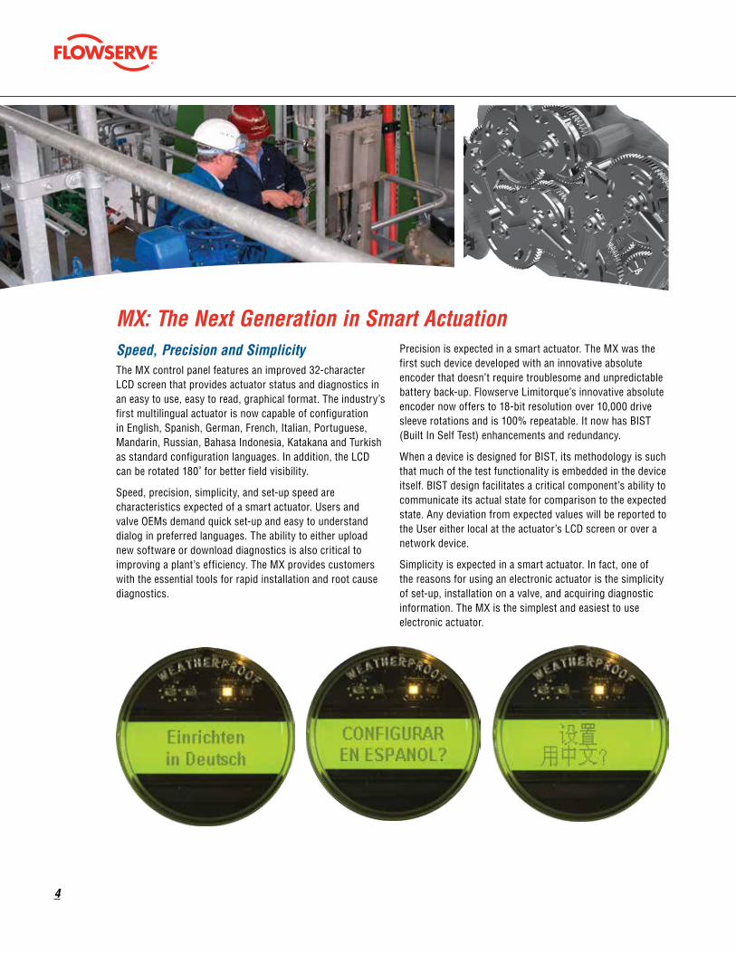
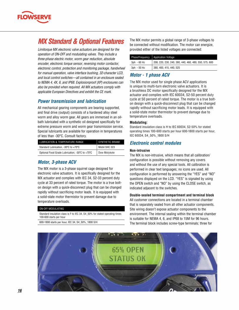
Speed, Precision and SimplicityThe MX control panel features an improved 32-character LCD screen that provides actuator status and diagnostics in an easy to use, easy to read, graphical format. The industry’s first multilingual actuator is now capable of configuration in English, Spanish, German, French, Italian, Portuguese, Mandarin, Russian, Bahasa Indonesia, Katakana and Turkish as standard configuration languages. In addition, the LCD can be rotated 180˚ for better field visibility.
Speed, precision, simplicity, and set-up speed are characteristics expected of a smart actuator. Users and valve OEMs demand quick set-up and easy to understand dialog in preferred languages. The ability to either upload new software or download diagnostics is also critical to improving a plant’s efficiency. The MX provides customers with the essential tools for rapid installation and root cause diagnostics.
Precision is expected in a smart actuator. The MX was the first such device developed with an innovative absolute encoder that doesn’t require troublesome and unpredictable battery back-up. Flowserve Limitorque’s innovative absolute encoder now offers to 18-bit resolution over 10,000 drive sleeve rotations and is 100% repeatable. It now has BIST (Built In Self Test) enhancements and redundancy.
When a device is designed for BIST, its methodology is such that much of the test functionality is embedded in the device itself. BIST design facilitates a critical component’s ability to communicate its actual state for comparison to the expected state. Any deviation from expected values will be reported to the User either local at the actuator’s LCD screen or over a network device.
Simplicity is expected in a smart actuator. In fact, one of the reasons for using an electronic actuator is the simplicity of set-up, installation on a valve, and acquiring diagnostic information. The MX is the simplest and easiest to use electronic actuator.
MX: The Next Generation in Smart Actuation
flowserve.com
5
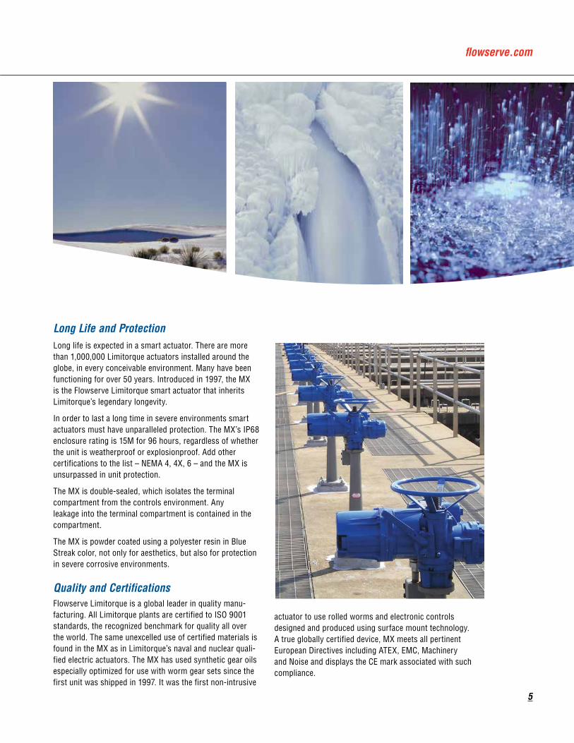
Long life is expected in a smart actuator. There are more than 1,000,000 Limitorque actuators installed around the globe, in every conceivable environment. Many have been functioning for over 50 years. Introduced in 1997, the MX is the Flowserve Limitorque smart actuator that inherits Limitorque’s legendary longevity.
In order to last a long time in severe environments smart actuators must have unparalleled protection. The MX’s IP68 enclosure rating is 15M for 96 hours, regardless of whether the unit is weatherproof or explosionproof. Add other certifications to the list – NEMA 4, 4X, 6 – and the MX is unsurpassed in unit protection.
The MX is double-sealed, which isolates the terminal compartment from the controls environment. Any leakage into the terminal compartment is contained in the compartment.
The MX is powder coated using a polyester resin in Blue Streak color, not only for aesthetics, but also for protection in severe corrosive environments.
Quality and CertificationsFlowserve Limitorque is a global leader in quality manu-facturing. All Limitorque plants are certified to ISO 9001 standards, the recognized benchmark for quality all over the world. The same unexcelled use of certified materials is found in the MX as in Limitorque’s naval and nuclear quali-fied electric actuators. The MX has used synthetic gear oils especially optimized for use with worm gear sets since the first unit was shipped in 1997. It was the first non-intrusive
actuator to use rolled worms and electronic controls designed and produced using surface mount technology. A true globally certified device, MX meets all pertinent European Directives including ATEX, EMC, Machinery and Noise and displays the CE mark associated with such compliance.
Long Life and Protection
6
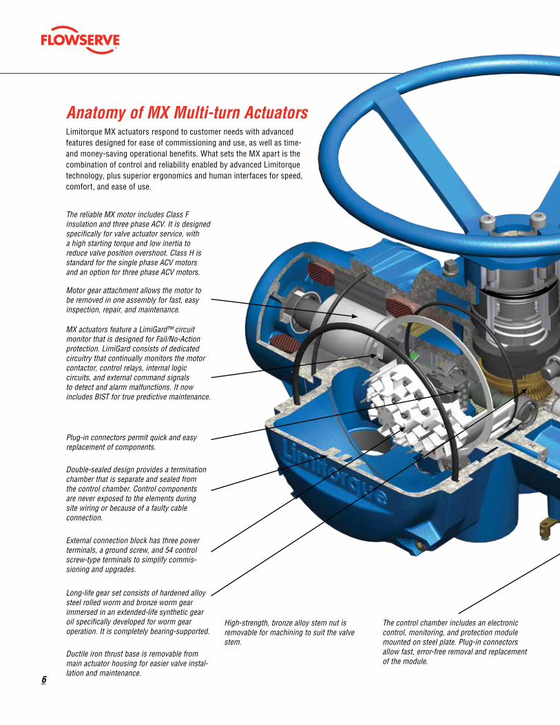
The reliable MX motor includes Class F insulation and three phase ACV. It is designed specifically for valve actuator service, with a high starting torque and low inertia to reduce valve position overshoot. Class H is standard for the single phase ACV motors and an option for three phase ACV motors.
Motor gear attachment allows the motor to be removed in one assembly for fast, easy inspection, repair, and maintenance.
MX actuators feature a LimiGard™ circuit monitor that is designed for Fail/No-Action protection. LimiGard consists of dedicated circuitry that continually monitors the motor contactor, control relays, internal logic circuits, and external command signals to detect and alarm malfunctions. It now includes BIST for true predictive maintenance.
Plug-in connectors permit quick and easy replacement of components.
Double-sealed design provides a termination chamber that is separate and sealed from the control chamber. Control components are never exposed to the elements during site wiring or because of a faulty cable connection.
External connection block has three power terminals, a ground screw, and 54 control screw-type terminals to simplify commis-sioning and upgrades.
Long-life gear set consists of hardened alloy steel rolled worm and bronze worm gear immersed in an extended-life synthetic gear oil specifically developed for worm gear operation. It is completely bearing-supported.
Ductile iron thrust base is removable from main actuator housing for easier valve instal-lation and maintenance.
High-strength, bronze alloy stem nut is removable for machining to suit the valve stem.
The control chamber includes an electronic control, monitoring, and protection module mounted on steel plate. Plug-in connectors allow fast, error-free removal and replacement of the module.
Anatomy of MX Multi-turn ActuatorsLimitorque MX actuators respond to customer needs with advanced features designed for ease of commissioning and use, as well as time- and money-saving operational benefits. What sets the MX apart is the combination of control and reliability enabled by advanced Limitorque technology, plus superior ergonomics and human interfaces for speed, comfort, and ease of use.
flowserve.com
7
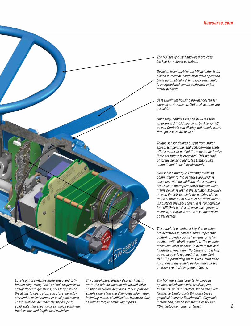
Local control switches make setup and cali-bration easy, using “yes” or “no” responses to straightforward questions, plus they provide the ability to open, stop, and close the actu-ator and to select remote or local preferences. These switches are magnetically coupled, solid state Hall effect devices, which eliminate troublesome and fragile reed switches.
The control panel display delivers instant, up-to-the-minute actuator status and valve position in eleven languages. It also provides simple calibration and diagnostic information, including motor, identification, hardware data, as well as torque profile log reports.
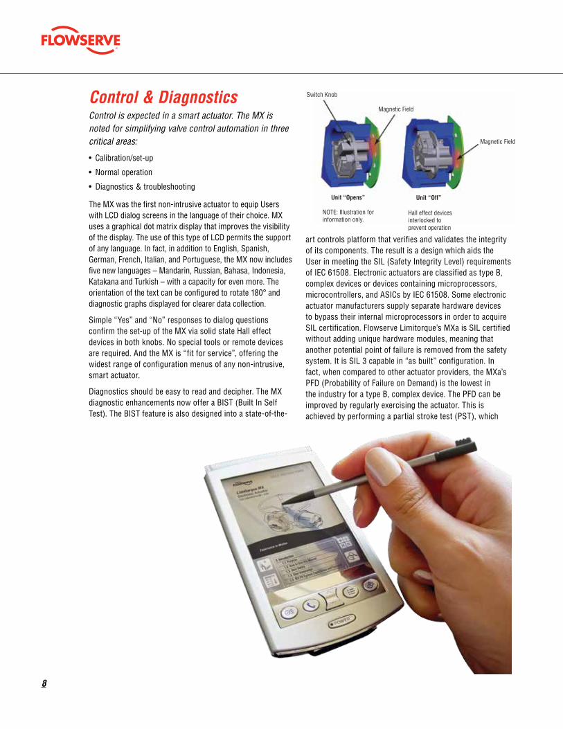
The MX offers Bluetooth technology as optional which connects, receives, and transmits, up to 10 meters. When used with Flowserve Limitorque’s Windows based graphical interface Dashboard™, diagnostic information, can be transferred easily to a PDA, laptop computer or tablet.
The absolute encoder, a key that enables MX actuators to achieve 100% repeatable control, provides optical sensing of valve position with 18-bit resolution. The encoder measures valve position in both motor and handwheel operation. No battery or back-up power supply is required. It is redundant (B.I.S.T.), permitting up to a 50% fault toler-ance, ensuring reliable performance in the unlikely event of component failure.
Flowserve Limitorque’s uncompromising commitment to “no batteries required” is enhanced with the addition of the optional MX Quik uninterrupted power transfer when mains power is lost to the actuator. MX-Quick powers the S/R contacts for updated status to the control room and also provides limited visibility of the LCD screen. It is configurable for “MX Quik time” and, once main power is restored, is available for the next unforeseen power outage.
Optionally, controls may be powered from an external 24 VDC source as backup for AC power. Controls and display will remain active through loss of AC power.
Torque sensor derives output from motor speed, temperature, and voltage—and shuts off the motor to protect the actuator and valve if the set torque is exceeded. This method of torque sensing indicates Limitorque’s commitment to be fully electronic.
Cast aluminum housing powder-coated for extreme environments. Optional coatings are available.
Declutch lever enables the MX actuator to be placed in manual, handwheel-drive operation. Lever automatically disengages when motor is energized and can be padlocked in the motor position.
The MX heavy-duty handwheel provides backup for manual operation.
8
Control is expected in a smart actuator. The MX is noted for simplifying valve control automation in three critical areas:
• Calibration/set-up
• Normal operation
• Diagnostics & troubleshooting
The MX was the first non-intrusive actuator to equip Users with LCD dialog screens in the language of their choice. MX uses a graphical dot matrix display that improves the visibility of the display. The use of this type of LCD permits the support of any language. In fact, in addition to English, Spanish, German, French, Italian, and Portuguese, the MX now includes five new languages – Mandarin, Russian, Bahasa, Indonesia, Katakana and Turkish – with a capacity for even more. The orientation of the text can be configured to rotate 180° and diagnostic graphs displayed for clearer data collection.
Simple “Yes” and “No” responses to dialog questions confirm the set-up of the MX via solid state Hall effect devices in both knobs. No special tools or remote devices are required. And the MX is “fit for service”, offering the widest range of configuration menus of any non-intrusive, smart actuator.
Diagnostics should be easy to read and decipher. The MX diagnostic enhancements now offer a BIST (Built In Self Test). The BIST feature is also designed into a state-of-the-
art controls platform that verifies and validates the integrity of its components. The result is a design which aids the User in meeting the SIL (Safety Integrity Level) requirements of IEC 61508. Electronic actuators are classified as type B, complex devices or devices containing microprocessors, microcontrollers, and ASICs by IEC 61508. Some electronic actuator manufacturers supply separate hardware devices to bypass their internal microprocessors in order to acquire SIL certification. Flowserve Limitorque’s MXa is SIL certified without adding unique hardware modules, meaning that another potential point of failure is removed from the safety system. It is SIL 3 capable in “as built” configuration. In fact, when compared to other actuator providers, the MXa’s PFD (Probability of Failure on Demand) is the lowest in the industry for a type B, complex device. The PFD can be improved by regularly exercising the actuator. This is achieved by performing a partial stroke test (PST), which
Control & Diagnostics Switch Knob
Magnetic Field
Magnetic Field
Unit “Opens” Unit “Off”
NOTE: Illustration for information only.
Hall effect devices interlocked to prevent operation
flowserve.com
9
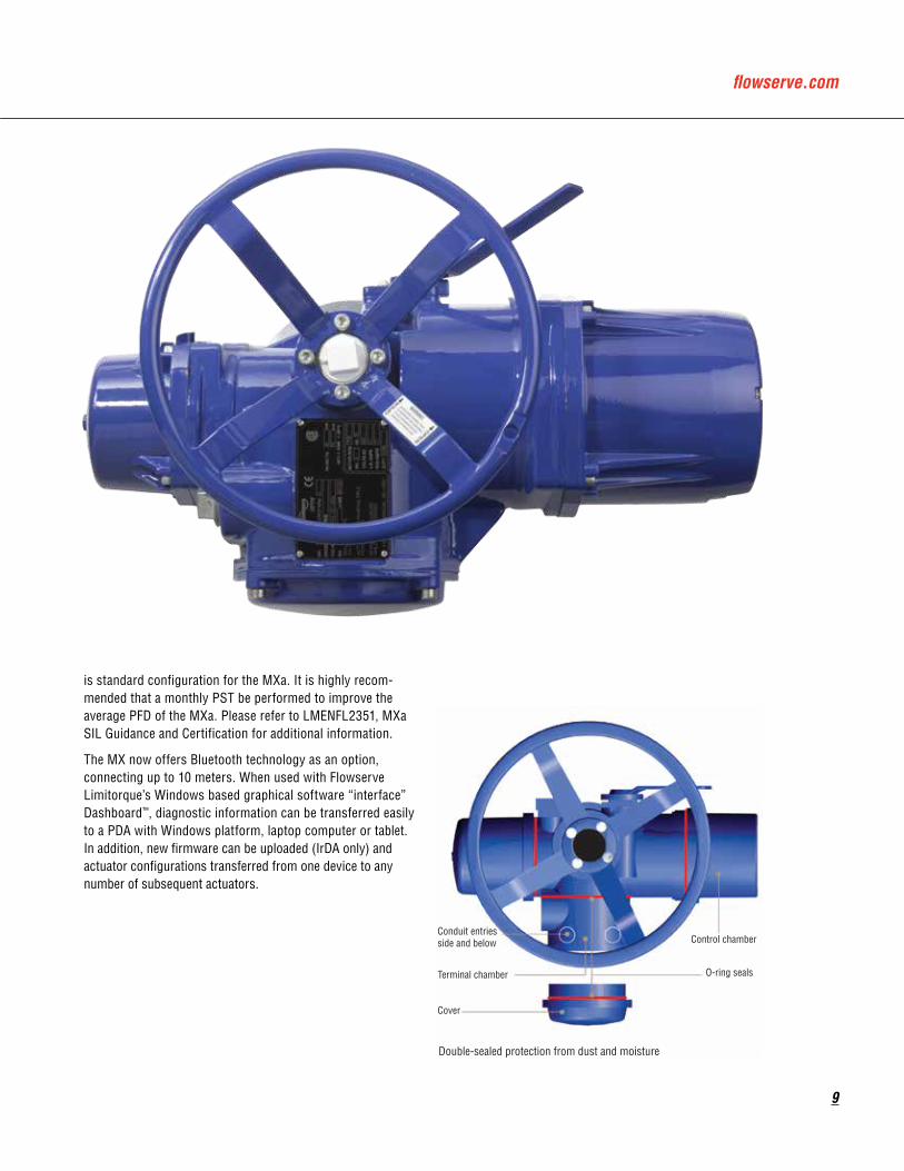
is standard configuration for the MXa. It is highly recom-mended that a monthly PST be performed to improve the average PFD of the MXa. Please refer to LMENFL2351, MXa SIL Guidance and Certification for additional information.
The MX now offers Bluetooth technology as an option, connecting up to 10 meters. When used with Flowserve Limitorque’s Windows based graphical software “interface” Dashboard™, diagnostic information can be transferred easily to a PDA with Windows platform, laptop computer or tablet. In addition, new firmware can be uploaded (IrDA only) and actuator configurations transferred from one device to any number of subsequent actuators.
Conduit entries side and below
Terminal chamber O-ring seals
Control chamber
Cover
Double-sealed protection from dust and moisture
10
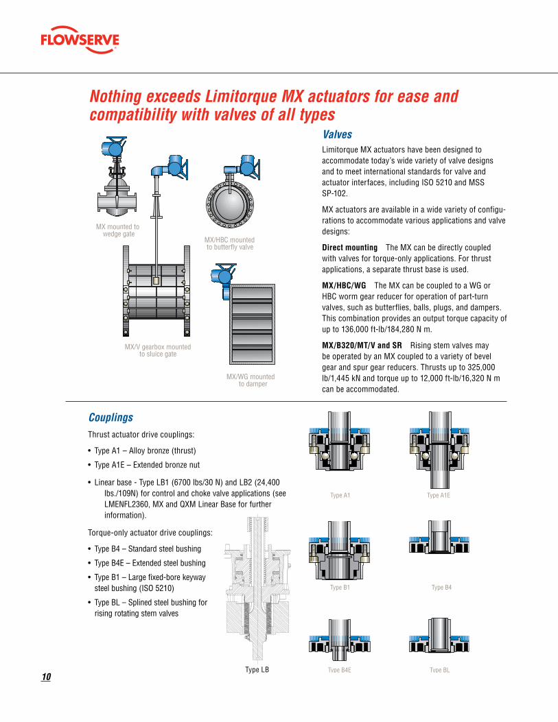
Nothing exceeds Limitorque MX actuators for ease and compatibility with valves of all types
ValvesLimitorque MX actuators have been designed to accommodate today’s wide variety of valve designs and to meet international standards for valve and actuator interfaces, including ISO 5210 and MSS SP-102.
MX actuators are available in a wide variety of configu-rations to accommodate various applications and valve designs:
Direct mounting The MX can be directly coupled with valves for torque-only applications. For thrust applications, a separate thrust base is used.
MX/HBC/WG The MX can be coupled to a WG or HBC worm gear reducer for operation of part-turn valves, such as butterflies, balls, plugs, and dampers. This combination provides an output torque capacity of up to 136,000 ft-lb/184,280 N m.
MX/B320/MT/V and SR Rising stem valves may be operated by an MX coupled to a variety of bevel gear and spur gear reducers. Thrusts up to 325,000 lb/1,445 kN and torque up to 12,000 ft-lb/16,320 N m can be accommodated.
MX mounted towedge gate
MX/V gearbox mountedto sluice gate
MX/HBC mountedto butterfly valve
MX/WG mountedto damper
CouplingsThrust actuator drive couplings:
• Type A1 – Alloy bronze (thrust)
• Type A1E – Extended bronze nut
• Linear base - Type LB1 (6700 lbs/30 N) and LB2 (24,400 lbs./109N) for control and choke valve applications (see LMENFL2360, MX and QXM Linear Base for further information).
Torque-only actuator drive couplings:
• Type B4 – Standard steel bushing
• Type B4E – Extended steel bushing
• Type B1 – Large fixed-bore keyway steel bushing (ISO 5210)
• Type BL – Splined steel bushing for rising rotating stem valves
Type A1 Type A1E
Type B4
Type B4E Type BL
Type B1
Type LB
flowserve.com
11
Smart actuators should have enabling technologies that ensure integrity and dependability. The MX offers three.
Limigard — now with BIST
Enhanced reliability for optimal plant operations and reduced troubleshooting costs are the primary benefits of Limitorque’s unique smart actuator monitor: LimiGard.
When LimiGard wiring diagrams are followed, LimiGard continually monitors the control relays, internal logic circuits, and external command signals, comparing them to reference conditions. This virtually eliminates the possibility that an actuator malfunction can occur without prompt detection and alarm communication. In the event of a malfunction, LimiGard takes over and supervises the actuator’s response characteristics, maximizing safety and predictability. Fault Insertion Tests confirm this Fail/No-Action philosophy built into every MX actuator.
A state-of-the-art electronic actuator such as the MX should include means for verifying and validating that its compo-nents are designed with Built-In-Self-Test (BIST) capabilities. Selecting the MX, which incorporates a high level of BIST, can contribute greatly to the integrity and reliability of process applications and enhance the ability of a safety system to achieve its highest possible SIL rating.
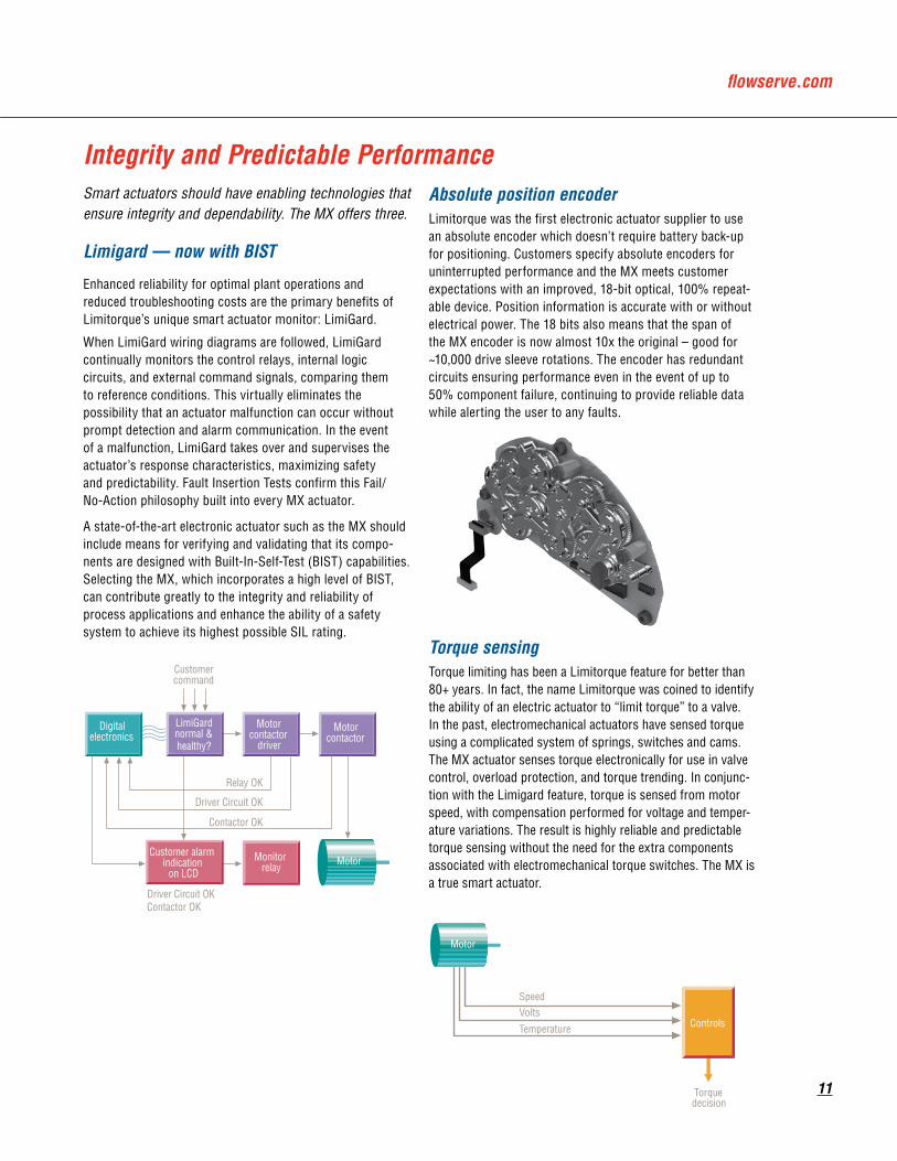
Absolute position encoderLimitorque was the first electronic actuator supplier to use an absolute encoder which doesn’t require battery back-up for positioning. Customers specify absolute encoders for uninterrupted performance and the MX meets customer expectations with an improved, 18-bit optical, 100% repeat-able device. Position information is accurate with or without electrical power. The 18 bits also means that the span of the MX encoder is now almost 10x the original – good for ~10,000 drive sleeve rotations. The encoder has redundant circuits ensuring performance even in the event of up to 50% component failure, continuing to provide reliable data while alerting the user to any faults.
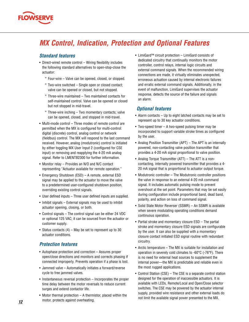
Torque sensingTorque limiting has been a Limitorque feature for better than 80+ years. In fact, the name Limitorque was coined to identify the ability of an electric actuator to “limit torque” to a valve. In the past, electromechanical actuators have sensed torque using a complicated system of springs, switches and cams. The MX actuator senses torque electronically for use in valve control, overload protection, and torque trending. In conjunc-tion with the Limigard feature, torque is sensed from motor speed, with compensation performed for voltage and temper-ature variations. The result is highly reliable and predictable torque sensing without the need for the extra components associated with electromechanical torque switches. The MX is a true smart actuator.
Integrity and Predictable Performance
Motor
SpeedVolts
Temperature Controls
Torquedecision
Motor
Customercommand
Digitalelectronics
LimiGardnormal &healthy?
Motorcontactor
driver
Motorcontactor
Relay OK
Driver Circuit OK
Contactor OK
Customer alarmindication
on LCDMonitor
relay
Driver Circuit OKContactor OK
12
Standard features• Direct-wired remote control – Wiring flexibility includes
the following standard alternatives to open-stop-close the actuator:
° Four-wire – Valve can be opened, closed, or stopped.
° Two-wire switched – Single open or closed contact; valve can be opened or closed, but not stopped.
° Three-wire maintained – Two maintained contacts for self-maintained control. Valve can be opened or closed but not stopped in mid-travel.
° Three-wire inching – Two momentary contacts; valve can be opened, closed, and stopped in mid-travel.
• Multi-mode control – Three modes of remote control are permitted when the MX is configured for multi-control: digital (discrete) control, analog control or network (fieldbus) control. The MX will respond to the last command received. However, analog (modutronic) control is initiated by either toggling MX User Input 2 (configured for CSE input) or removing and reapplying the 4-20 mA analog signal. Refer to LMENTB2300 for further information.
• Monitor relay – Provides an N/O and N/C contact representing “Actuator available for remote operation.”
• Emergency Shutdown (ESD) – A remote, external ESD signal may be applied to the actuator to move the valve to a predetermined user-configured shutdown position, overriding existing control signals.
• User defined inputs – Three user defined inputs are supplied.
• Inhibit signals – External signals may be used to inhibit actuator opening, closing, or both.
• Control signals – The control signal can be either 24 VDC or optional 125 VAC; it can be sourced from the actuator or customer supply.
• Status contacts (4) – May be set to represent up to 30 actuator conditions.
Protection features• Autophase protection and correction – Assures proper
open/close directions and monitors and corrects phasing if connected improperly. Prevents operation if a phase is lost.
• Jammed valve – Automatically initiates a forward/reverse cycle to free jammed valves.
• Instantaneous reversal protection – Incorporates the proper time delay between the motor reversals to reduce current surges and extend contactor life.
• Motor thermal protection – A thermistor, placed within the motor, protects against overheating.
• LimiGard™ circuit protection – LimiGard consists of dedicated circuitry that continually monitors the motor controller, control relays, internal logic circuits and external command signals. When the recommended wiring connections are made, it virtually eliminates unexpected, erroneous actuation caused by internal electronic failures and erratic external command signals. Additionally, in the event of malfunction, LimiGard supervises the actuator response, detects the source of the failure and signals an alarm.
Optional features• Alarm contacts – Up to eight latched contacts may be set to
represent up to 30 key actuator conditions.
• Two-speed timer – A two-speed pulsing timer may be incorporated to support variable stroke times as configured by the user.
• Analog Position Transmitter (APT) – The APT is an internally powered, non-contacting valve position transmitter that provides a 4-20 mA signal proportional to valve position.
• Analog Torque Transmitter (ATT) – The ATT is a non-contacting, internally powered transmitter that provides a 4-20 mA signal that is proportional to actuator output torque.
• Modutronic controller – The Modutronic controller positions the valve in response to an external 4-20 mA command signal. It includes automatic pulsing mode to prevent overshoot at the set point. Parameters that may be set easily during configuration include proportional band, dead band, polarity, and action on loss of command signal.
• Solid State Motor Reverser (SSMR) – An SSMR is available when severe modulating operating conditions demand continuous operation.
• Partial stroke and momentary closure ESD – The partial stroke and momentary closure ESD signals are configurable by the user. It can also be supplied with a momentary closure contact initiated ESD signal routine with redundant circuitry.
• Arctic temperature – The MX is suitable for installation and operation in severely cold climates to -60°C (-76°F). There is no need for external heat sources to supplement the internal power—the MX is predictable and reliable even in the most rugged applications.
• Control Station (CSE) – The CSE is a separate control station designed for the operation of inaccessible actuators. It is available with LEDs, Remote/Local and Open/Close selector switches. The CSE may be powered by the actuator internal supply, provided wire resistance and other external loads do not limit the available signal power presented to the MX.
MX Control, Indication, Protection and Optional Features

flowserve.com
13
• Isolation and Load Break Switches – Isolation and Load Break Switches can be supplied for the incoming three-phase supply to the actuator. These may be coupled directly to the actuator for weatherproof (WP) applications only or supplied separately for mounting by user. The enclosure is suitable for weatherproof or temporary submersion service. An explosion-proof (XP) isolation switch is also available for user mounting and is suitable for mounting with all MX actuators. Please contact factory for availability.
• Negative Switching – When remote control systems require the negative pole of the circuit supply to be switched to positive earth, a simple software change is made.
• MX Quik – After the actuator has been powered by line power for one hour, it will automatically withstand most power outages while maintaining the correct state of the S or R status contacts—even if the user repositions the actuator manually with the handwheel. To maximize its self-power time while the line power is lost, the actuator places itself in its lowest possible power usage mode. The LCD will darken
(sleep mode) until it is activated for viewing. The LCD can be activated by moving the black knob to OPEN (YES) or by moving the actuator with the handwheel. After 10 seconds of inactivity, the LCD will return to sleep mode.
Bluetooth capable optionsStandard low power wireless communication path to the actuator enables monitoring and configuration of the unit up to 10m in any direction via a Bluetooth equipped PC, PDA, smart cell phone, etc. FHSS (Frequency Hopping Spread Spectrum) allows a reliable communication link even in a “noisy” environment and 128 bit data encryption can be enabled to protect the privacy of the link. MX Dashboard configuration / diagnostics tools can use the Bluetooth link as a means for communicating with the actuator. A visible blue LED in the controls LCD window on the face of the actuator signifies an active Bluetooth link to the actuator has been established.
The MX provides a comprehensive network option portfolio to the User. Network solutions are improved with the addition of DeviceNet to complement Modbus, Foundation Fieldbus H1, Profibus DP_V1 and Profibus PA. MX provides the User with predictable, reliable, and safe operation for years to come, in applications which are subject to the most rigorous requirements and environmental extremes.
DDC Modbus (Distributed Digital Control) CommunicationDDC is Flowserve Limitorque’s digital communication control system that provides the ability to control and monitor up to 250 actuators over a single twisted-pair cable. The communication network employs Modbus protocol on an RS-485 network and is redundant. Redundancy assures that any single break or short in the communication cable will not disable any actuators. Each actuator has included an addressable field unit that communicates over the twisted pair network and executes open, close, stop, ESD, and GO TO position commands. The field unit also communicates all actuator status and alarm diagnostic messages over the same communication network.
DDC Network• Single-ended loop (consult factory)
• Modbus protocol
• High speed – up to 19.2 k baud
Master Station IIIMX units equipped with DDC can be controlled via Flowserve
Limitorque’s Master Station III. It includes:
• Host interface – Industry standard Modbus Rtu, ASCI, UDP, and TCP/IP protocols and control
• 5.6” TFT touch-screen display for network configuration status
• Configurable polling sequence priority
• Network time protocol for time synchronization of alarms/diagnostics data to host device
• Modular hot-swappable redundant design
• E-mail notifications of alarm conditions
• Data/event logging
Network Communications
14
Foundation Fieldbus communication with Device Type Manager (DTM) technologyThe MX can be fitted with Foundation Fieldbus protocol that complies with the IEC 61158-2 Fieldbus H1 standard. The field unit device is able to support several topologies such as point- to-point, bus with spurs, daisy chain, tree or a combination of these. The FF device has network features that include:• Link Active Scheduler that controls the system• High-speed communications up to 31.25 kbits/sec• Publisher-subscriber communication• Input and output function blocks• Device descriptions• Network communication• Configurable by userLink Active Scheduler communication: Fieldbus segments have one active Link Active Scheduler (LAS) at a given time, which is the bus arbiter, and does the following:
– Recognizes and adds new devices to the link– Removes non-responsive devices from the link– Schedules control activity in, and communication
activity between, devices– Regularly polls devices for process data– Distributes a priority-driven token to devices for
unscheduled transmissions- DTM technology includes PID (proportional integral
derivative) and partial stroke (PS) feature
PROFIBUS DP V1 communication with DTMThe MX can be fitted with Profibus DP_V1 protocol field units that comply with EN50170 Fieldbus Standard for RS-485 communications. The device supports several topologies such as point-to-point, bus with spurs, daisy chain, tree or a combi-nation of these. The PB device has network features that include:• High-speed communications up to 1.5 Mbps• Master-to-slave communication• Standby communication channel• Analog and digital input and output function blocks• Device descriptions configurable by user• High-Speed Data Exchange – Startup Sequence• Power On / Reset – Power On / Reset of master or slave • Parameterization – download of parameters into field
device (selected during configuration by the user) • I/O Configuration – download of I/O configuration into the
field device (selected during configuration by the user) • Data Exchange – cyclic data exchange (I/O Data) and field
device reports diagnostics• Redundant Profibus DP with single or multiple –
master communications
PROFIBUS PA communication with DTMA Profibus PA protocol is available and complies with EN50170 Fieldbus Standard and Fieldbus physical layer per IEC 61158-2 for communications. The device supports several topologies such as point-to-point, bus with spurs,
daisy chain, tree or a combination of these. The PB device has network features that include:
• High-speed communications up to 31.25 kbits/s with Manchester coding
• Master-to-slave communication• Bus powered for 9-32 VDC and 15 mA per actuator• Standby communication channel• Analog and digital input and output function blocks• Device descriptions• Configurable by userThe Profibus DP-V1/PA DTM V 1.0 is a software component that contains device-specific application information. The DTM can be integrated into engineering and FDT frame applications, such as stand-alone commissioning tools or asset management systems that are equipped with FDT interfaces. FDT technology is independent from any specific communication protocol, device software or host system, allowing any device to be accessed from any DCS host through any protocol.
DeviceNetDeviceNet complies with CAN-based protocol and provides the following features:
• DeviceNet Group 2 Server implementation • Master-to-slave communication• Bus-powered network interface allows power alarm
information to be communicated when actuator loses main power; the actuator does NOT drop off the network when power is lost
• Standard polled I/O connection• Standard bit strobed I/O connection• Standard change of state / cyclic I/O connection• Standard explicit connections defined as:
– Various assembly objects and sizes that allow the network user to determine how much data to transfer to accommodate network installation data throughput requirements
– Automatic baud rate detection– Node address configurable via local setup menu or via
the remote network user – Broadcast or group network originated ESD support
HART Communication with DTM• Complies with HART Communication Protocol
Specification (Document HCF_SPEC-13) for Revision 7.3 • Digital signal on conventional 4-20m ADC analog signal • 1200 bps binary phase — continuous Frequency-Shift-
Keying • Master-Slave communication method • Point-to-point or multi-drop network topology • Distances up to 1800 meters/network (up to 15 devices) • EDDL (IEC 61804-2, EDDL) with methods for all supported
Common Practice & Device Specific commands”

flowserve.com
15
MX Series Performance Ratings for Units 05 through 150MX-05 through MX-40 (three-phase: 50 Hz/380, 400, 415, and 440 Volt: 60 Hz/208, 230, 380, 460, 480, 525, 575 Volt)
MX-85 through MX-150 (three-phase: 50 Hz/380*, 400, and 415 Volt: 60 Hz/380, 460, 575 Volt)
MX-05 through MX-10 (single phase ACV: 50 Hz/240, and 60 Hz/115, 125, 230)
*380/50 multiply by 0.9
Output Speed (RPM)
MX-05 MX-10 MX-20 MX-40 MX-85 MX-140 MX-150
Rated Output Torque
60 Hz 50 Hz ft-lb N m ft-lb N m ft-lb N m ft-lb N m ft-lb N m ft-lb N m ft-lb N m
1826405277
1522334365
55 75 125 170 225 305 440 597 N/A N/A N/A N/A N/A N/A
55 75 125 170 225 305 440 597 850 1153 1500 2036 N/A N/A
55 75 125 170 225 305 440 597 1225 1662 1700 2307 N/A N/A
55 75 125 170 225 305 440 597 1150 1561 1600 2171 N/A N/A
48 65 107 145 178 241 345 468 850 1153 1200 1628 N/A N/A100 1311 84 1101 39 53 89 121 148 201 286 388 600 814 815 1105 1500 2036155 1701 127 1431 41 56 89 121 140 190 260 353 450 611 650 882 1150 1561200 165 34 46 73 99 114 155 210 285 N/A N/A N/A N/A N/A N/A
Note 1: MX-85, MX-140 and MX-150
lb kN lb kN lb kN lb kN lb kN lb kN lb kN
Thrust Ratings (lb/kN) 8000 35 15000 66 25000 111 36000 160 50000 222 75000 333 75000 333
B4 Base (Torque Only) lb kg lb kg lb kg lb kg lb kg lb kg lb kgWeights (lb/kg) 52 24 65 29 109 49 133 60 250 114 300 136 431 182
A1 Base (Thrust Only) Weight lb kg
MX-05 & MX-10 9 4MX-20 & MX-40 29 13
MX-85 w/ F16/FA16 base 72 33
MX-140/MX-150 w/ F25/FA25 base 111 50
Maximum Stem CapacityType A Couplings in. mm in. mm in. mm in. mm in. mm in. mm in. mm
Type A1 1.26 32 1.57 40 2.36 60 2.64 67 3.50 88 3.50 88 3.50 88
Type A1E (Extended Nut) 1.26 32 1.57 40 2.36 60 2.64 67 3.50 88 3.50 88 3.50 88
Type B Couplings (Torque Only)2 in. mm in. mm in. mm in. mm in. mm in. mm in. mm
Type B4 1 25.4 1.25 30 1.94 50 2.2 55 2.88 73 2.88 73 2.625 65
Type B4E (Extended) 0.75 19 0.91 22 1.56 41 1.78 46 2.25 57 2.25 57 2.625 65
Type B1 (Fixed Bore)3 N/A 42 N/A 42 N/A 60 N/A 60 N/A N/A N/A N/A N/A N/A
Type BL (Splined) 6 & 38 Splines 6 & 38 Splines 6 & 36 Splines 6 Splines N/A N/A N/A N/A N/A N/A
Maximum Bore and Keyway in. mm in. mm in. mm in. mm in. mm in. mm in. mm
Maximum Bore (B4) 1 25 1.25 30 1.94 50 2.2 55 2.75 65 2.65 65 2.625 65
Maximum Key dimensions 1/4 sq. 8 x 7 1/4 sq. 10 x 8 1/2 x 3⁄8 14 x 9 1/2 x 3⁄8 16 x 10
5 ⁄8 x 7 ⁄16
18 x 11
5 ⁄8 x 7 ⁄16
18 x 11
5 ⁄8 x 7⁄16
18 x 11
Maximum Bore (B4E) .75 18 0.91 22 1.56 41 1.78 46 2.25 56 2.25 56 2.5 65
Maximum Key dimensions 3⁄16 sq. 6 x 6 1/4 sq. 8 x 7 3⁄8 sq. 12 x 8 1/2 x 3⁄8 14 x 9 1/2 x 3⁄8 16 x 10
1/2 x 3⁄8 16 x 10
0.625 sq.
18 x 11
Note 2: Maximum bores for Type B couplings may require rectangular keys.
Note 3: Available in ISO base only.
MX-05 MX-10 MX-20 MX-40 MX-85 MX-140 MX-150
Mounting Base (MSS SP-102/ISO 5210) FA10/F10 FA10/F10 FA14/F14 FA14/F14 FA16/F16 FA25/F25 FA25/F25
Handwheel Ratio (STD/Optional) Direct Direct/8:1 Direct/12:1 Direct/24:1 16/48 16/48 16/48
Side-Mounted Handwheel Efficiencies N/A 52% 54% 51% 53%/51%4 53%/51%4 53%/51%4
Note 4: Efficiencies for MX-85, MX-140 and 150 are 51% with SGA and 53% without SGA.
Linear Base Weight lb kg
LB1 24 11LB2 65 29.5
16
MX Standard & Optional FeaturesLimitorque MX electronic valve actuators are designed for the operation of ON-OFF and modulating valves. They include a three-phase electric motor, worm gear reduction, absolute encoder, electronic torque sensor, reversing motor contactor, electronic control, protection and monitoring package, handwheel for manual operation, valve interface bushing, 32-character LCD, and local control switches—all contained in an enclosure sealed to NEMA 4, 4X, 6, and IP68. Explosionproof (XP) enclosures can also be provided when required. All MX actuators comply with applicable European Directives and exhibit the CE mark.
Power transmission and lubrication All mechanical gearing components are bearing supported, and final drive (output) consists of a hardened alloy steel worm and alloy worm gear. All gears are immersed in an oil-bath lubricated with a synthetic oil designed specifically for extreme pressure worm and worm gear transmission service. Special lubricants are available for operation in temperatures of less than -30°C. Consult factory.
LUBRICATION & TEMPERATURE RANGE SYNTHETIC BRAND
Standard Lubrication, -30ºC to +70ºC Mobil SHC 323
Optional Food Grade Lubrication, -30ºC to +70ºC Dow Molykote
Motor, 3-phase ACVThe MX motor is a 3-phase squirrel cage designed for electronic valve actuators. It is specifically designed for the MX actuator and complies with IEC 34, S2-33 percent duty cycle at 33 percent of rated torque. The motor is a true bolt-on design with a quick-disconnect plug that can be changed rapidly without sacrificing motor leads. It is equipped with a solid-state motor thermistor to prevent damage due to temperature overloads.
ON-OFF MODULATING
Standard insulation class is F to IEC 34, S4_50% for stated operating times 100-600 starts per hour
600-1800 starts per hour, IEC 34, S4_50%_1800 S/H
The MX motor permits a global range of 3-phase voltages to be connected without modification. The motor can energize, provided either of the listed voltages are connected:
Phase/Frequency Application Voltage
3ph - 60 Hz 208, 220, 230, 240, 380, 440, 460, 480, 550, 575, 600
3ph - 50 Hz 380, 400, 415, 440, 525
Motor - 1 phase ACVThe MX motor used for single phase ACV applications is unique to multi-turn electronic valve actuators. It is a brushless DC motor specifically designed for the MX actuator and complies with IEC 60034, S2-50 percent duty cycle at 50 percent of rated torque. The motor is a true bolt-on design with a quick-disconnect plug that can be changed rapidly without sacrificing motor leads. It is equipped with a solid-state motor thermistor to prevent damage due to temperature overloads.
Modulating:Standard insulation class is H to IEC 60034, S2-50% for stated operating times 100-600 starts per hour 600-1800 starts per hour, IEC 60034, S4_50%_1800 S/H
Electronic control modules Non-intrusive The MX is non-intrusive, which means that all calibration/configuration is possible without removing any covers and without the use of any special tools. All calibration is performed in clear text languages; no icons are used. All configuration is performed by answering the “YES” and “NO” questions displayed on the LCD. “YES” is signaled by using the OPEN switch and “NO” by using the CLOSE switch, as indicated adjacent to the switches.
Double-sealed terminal compartment and terminal block All customer connections are located in a terminal chamber that is separately sealed from all other actuator components. Site wiring doesn’t expose actuator components to the environment. The internal sealing within the terminal chamber is suitable for NEMA 4, 6, and IP68 to 15M for 96 hours. The terminal block includes screw-type terminals; three for
flowserve.com
17
ControlsThe controls are all solid state and include power and logic circuit boards and a motor controller that performs as the motor reverser, all mounted to a steel plate and attached in the control compartment with captive screws. All internal wiring is flame resistant, rated 105°C, and UL/CSA listed.
The controls are housed in the ACP (Actuator Control Panel) cover, and the logic module uses solid-state Hall-effect devices for local communication and configuration. A 32-character, graphical LCD is included to display valve position as a percent of open, 0-100% and current actuator status. Red and green LEDs are included to signal ‘Opened’ and ‘Closed,’ and are reversible, and a yellow LED to indicate ‘Valve Moving.’ A blue LED is included when the Bluetooth option is ordered. A padlockable LOCAL-STOP-REMOTE switch and an OPEN-CLOSE switch are included for local valve actuator control
Using the knobs and LCD screen the MX is configurable in 11 languages: English, Spanish, French, German, Portuguese, Italian, Mandarin, Russian, Bahasa Indonesia, Turkish and Katakana.
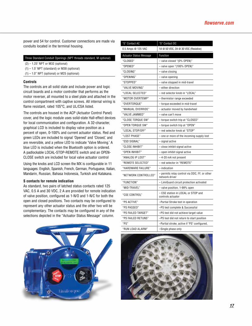
S contacts for remote indicationAs standard, two pairs of latched status contacts rated 125 VAC, 0.5 A and 30 VDC, 2 A are provided for remote indication of valve position, configured as 1-N/O and 1-N/C for both the open and closed positions. Two contacts may be configured to represent any other actuator status and the other two will be complementary. The contacts may be configured in any of the selections depicted in the “Actuator Status Message” column.
“S” Contact AC “S” Contact DC
0.5 Amps @ 125 VAC 1A @ 50 VDC, 2A @ 30 VDC (Resistive)
power and 54 for control. Customer connections are made via conduits located in the terminal housing.
Actuator Status Message Function
“CLOSED” – valve closed “(0% OPEN)”
“OPENED” – valve open “(100% OPEN)”
“CLOSING” – valve closing
“OPENING” – valve opening
“STOPPED” – valve stopped in mid-travel
“VALVE MOVING” – either direction
“LOCAL SELECTED” – red selector knob in “LOCAL”
“MOTOR OVERTEMP” – thermistor range exceeded
“OVERTORQUE” – torque exceeded in mid-travel
“MANUAL OVERRIDE” – actuator moved by handwheel
“VALVE JAMMED” – valve can’t move
“CLOSE TORQUE SW” – torque switch trip at “CLOSED”
“OPEN TORQUE SW” – torque switch trip at “OPEN”
“LOCAL STOP/OFF” – red selector knob at “STOP”
“LOST PHASE” – one or more of the incoming supply lost
“ESD SIGNAL” – signal active
“CLOSE INHIBIT” – close inhibit signal active
“OPEN INHIBIT” – open inhibit signal active
“ANALOG IP LOST” – 4-20 mA not present
“REMOTE SELECTED” – red selector in “REMOTE”
“HARDWARE FAILURE” – indication
“NETWORK CONTROLLED” – permits relay control via DDC, FF, or other network driver
“FUNCTION” – LimiGuard circuit protection activated
“MID-TRAVEL” – valve position, 1-99% open
“CSE CONTROL” – CSE station in LOCAL or STOP and controls actuator
“PS ACTIVE” –Partial Stroke test in operation
“PS PASSED” –PS test complete & Successful
“PS FAILED TARGET” –PS test did not achieve target value
“PS FAILED RETUNS” –PS test did not return to start position
“PS” –Partial stroke, active if "PS" configured,
“RUN LOAD ALARM” –Single phase only
Three Standard Conduit Openings (NPT threads standard, M optional)
(2) – 1.25" NPT or M32 (optional)
(1) – 1.5" NPT (standard) or M38 (optional)
(1) – 1.0” NPT (optional) or M25 (optional)
18
Monitor relay for remote indicationA monitor relay is included as standard and trips when the actuator is not available for remote operation. Both N/O and N/C contacts are included, rated 125 VAC, 0.5 A and 30 VDC, 2 A. The monitor relay can be configured for three additional fault indications: lost phase, valve jammed and motor Overtemp. The yellow LED will blink when the monitor relay is active. The user can disable the monitor relay, if necessary.
Remote controlDiscrete remote control (user supplied) may be configured as two, three or four wires for Open-Stop-Close control. Remote control functions may be powered by external 24 VDC, 110 VAC, or the actuator’s internal 24 VDC supply or optional 110 VAC supply. The internal supplies are protected against over current and short circuit faults and utilize optical isolation to minimize electromagnetic interference. Discrete control provides isolated commons for up to three selections.
Speed controlThe MX permits operational speeds in either Open and Closed directions to be set independently of each other. The MX also has an industry leading span for the optional two-speed timer.
Two-Speed Timer Span “ON” Pulse Two-Speed Timer Span “Off” Pulse
0.5 to 20 seconds (0.5 sec. increments)
1.0 to 200 seconds (1.0 sec. increments)
Monitor Relay AC Monitor Relay DC
0.5 Amps @ 125 VAC 1A @ 50 VDC, 2A @ 30 VDC (Resistive)
Signal Threshold for Voltage Values
Maximum Load
5.0 VAC/VDC maximum ‘OFF’ 24 VDC + 2 mA
19.2 VAC/VDC minimum ‘ON’ 110 VAC + 10 mA
Software LimigardA dedicated circuit to prevent undesired valve operation in the event of an internal circuit fault or erratic command signal is included as standard on each Limitorque electronic actuator. A single point failure will not result in erratic actuator movement nor will an open or short circuit in the internal circuit board logic energize the motor controller. The command inputs are optically coupled and require a valid signal pulse width from at least 250 ms to 350 ms to either turn on or off. In the event of an internal circuit fault, an alarm is signaled by tripping the monitor relay and through LCD indication. The control module also includes an auto reversal delay to inhibit high-current surges caused by rapid motor reversals.
Phase detection and correction (three phase)A phase correction circuit is included to correct motor rotation faults caused by incorrect site wiring or phase switching in the event of a power down. The phase correction circuit also detects the loss of a phase and disables operation to prevent motor damage. The monitor relay will trip and an error message is displayed on the LCD screen when loss of phase occurs.
Multi-mode remote controlThe MX is capable of being configured for multi-mode remote control, which permits discrete wiring for either two, three or four wires, or network (Fieldbuses) for Open-Stop-Close control and responds to the last signal received. The actuator can also distinguish analog control for modulating applications. The QX and MX products from Limitorque are the only smart actuators with such features.
ESDAn Emergency Shutdown (ESD) provision is included in each actuator, and the MX has up to three configurable inputs for ESD. The ESD signal(s) can be selected to override any existing signal and send the valve to its configured emergency position. Provision for an isolated common is standard.

flowserve.com
19
InhibitsThe MX has as standard provisions for inhibit movement and also contains up to three configurable inputs. Provision for an isolated common is also standard.
DiagnosticsThe MX contains similar diagnostic facilities as the QX. The values are included to accumulate and report the performance of the motor, encoder, motor controller, cycle time, handwheel operations, actuator ID, firmware revision and output turns. In addition, a torque profile of the reference baseline valve stroke and the last valve stroke is included. A feature for resetting the diagnostic odometer is also provided. All diagnostic information is displayed on the LCD and can be acquired over a network if Fieldbus options are purchased. The MX actuator has the ability for diagnostics information to be downloaded to a PC or PDA via both IRDA and Bluetooth ports using the Dashboard software.
Valve and actuator position sensingValve position is sensed by an 18-bit, optical, absolute position encoder with redundant position sensing circuits designed for Built-In-Self-Test (BIST). Each of the position sensing circuits is redundant, facilitating BIST. The BIST feature discerns which failures will signal a warning only and which require a warning plus safe shutdown of the actuator. Open and closed positions are stored in permanent, nonvolatile memory. The encoder measures valve position at all times, including both motor and handwheel operation, with or without power present, and without the use of a battery. The absolute encoder is capable of resolving ±7° of output shaft position over 10,000 output drive rotations. This design permits continuous monitoring of valve position during motor and handwheel operation. The encoder is 100% repeatable and requires no backup power source for operation. The output is used to control the open and closed valve position and measure and report valve position, as well as provide local and remote position feedback. The positioning accuracy is better than 99% for valves requiring 50 or more turns.
• Maximum actuator turns = 10,000 • Resolution = ± 7 degrees
20
Valve and actuator torque sensingThe MX and QX are the only electric actuators that sense torque electronically. A microprocessor calculates output torque from motor speed, voltage, and temperature. Torque limit may be set from 40–100% of rating in 1% increments. A “Jammed Valve Protection” feature, with automatic retry sequence, is included to de-energize the motor if the output torque requirement exceeds the boost torque. A boost function is included to prevent torque trip during initial valve unseating and during extreme arctic temperature operation (from 0ºC down to -60ºC). The MX monitors for “jammed valve” as a protection feature and initiates an automatic retry sequence if no movement occurs.
Exterior corrosion protectionThe MX actuator is coated with as standard a polymer powder coat suitable for exposure to an ASTM B117 salt spray test of 1,500 hours. External fasteners are 300 series stainless steel. Optional coatings are available by contacting factory.
Manual operationA handwheel and declutch lever are provided for manual operation. The handwheel is metal and changing from motor to manual operation is accomplished by engaging the declutch lever. Energizing the motor returns the MX to motor operation. The lever is padlockable in either motor or manual operation. Optional configurations for handwheels are available by consulting the factory.
Factory testingEvery MX actuator is factory tested to verify rated output torque, output speed, handwheel operation, local control, control power supply, valve jammed function, all customer inputs and outputs, motor current, motor thermistor, LCD and LED operation, direction of rotation, microprocessor checks and position-sensor checks. A report confirming successful completion of testing is included with the actuator. Special testing can also be performed by contacting the factory.
Design life and endurance testing• Design Life - One million drive sleeve turns is considered
typical life expectancy under normal operating conditions approved ambient working environments.
• Endurance – 50 million collective drive sleeve turns of endurance testing were performed on the MX for proof of design.
• AWWA C540-02 – “Standard for Power Actuating Devices for Valves and Sluice Gates” – 10,000 cycles with confirmation of specified torque and position accuracy.
Options Lost power buffer and 24 VDC UPS Terminals are included and can be used to optionally connect the electronic controls package, including display, to a backup 24 VDC power source. Another option is the MX Quik. Once the actuator has been powered by line power for one hour, it can automatically withstand most power outages while maintaining the correct state of the alarm and status contacts, even if the user repositions the actuator manually with the handwheel. To maximize its self-power time while the line power is lost, the actuator will place itself in its lowest possible power usage mode. The LCD will darken (sleep mode) until it is needed to be viewed. The LCD can be activated by moving the black knob to OPEN (YES) or by moving the actuator with the handwheel. After 7-8 seconds of inactivity, the LCD will return to sleep mode. This feature can last up to three hours and automatically recharges once main power is restored.
The use of batteries to perform this function is not required.
Analog Position Transmitter (APT) A non-contacting, internally powered, electrically isolated position transmitter can be included to provide a 4-20 mA or 0-10 VDC signal that is proportional to valve position.
Analog Torque Transmitter (ATT) A non-contacting, internally powered, electrically isolated torque transmitter can be included to provide a 4-20 mA or 0-10 VDC signal that is proportional to rated output torque.
Voltages or Currents for APT/ATT
Maximum/Minimum External Load - APT/ATT
4-20 mA 470 ohms - 99.9% accuracy/ 750 ohms for 99% accuracy
0-10 VDC 1000 ohms minimum - 99.9% accuracy/ 2700 ohms minimum - 99% accuracy

flowserve.com
21
Custom software—Momentary contact ESD and partial stroke ESDAn optional, custom software is available which, when combined with the unique safety features of the MX actuator, permits a unique scope of performance for partial stroke and emergency shutdown installations.
When enabled a user may set up the partial stroke and ESD signals as redundant digital inputs for safety. There are two signal inputs for either selection, and both must be in the active state in order for the specific function to occur.
If the partial stroke enable inputs are not active, in a fault state, or are released by the control logic and a signal is detected on the momentary ESD/PSESD input, then the actuator will perform the configured ESD operation. The momentary ESD/PSESD input will be ignored if there is a signal present for less than 100 msec, and is guaranteed to latch in the ESD/PSESD if the signal is present for greater than 800 msec. ESD is active until the control logic ESD release is given.
Please contact factory for application and purchase.
Modutronic option A controller that alters valve position in proportion to a 4-20 mA analog command signal can be ordered. Positioning is accomplished by comparing the command signal to a non-contacting internal position feedback. An automatic pulsing feature to prevent overshoot at the setpoint is included. Proportional bands, deadband, signal polarity, motion inhibits time, and fail are adjustable using either the Local control mode of configuration or MX/QX Dashboard. Deadband is adjustable to +/- 0.1% percent full span.
Relays for status and alarms Up to eight additional latching output contacts rated 250 VAC/30 VDC, 5 A and configurable to represent any actuator status in either N/O or N/C state are available. Please refer to “Status and Alarm Contacts for Remote Indication” for list of settings.
“R” Contact and Monitor Relay AC Ratings “S” Contact and Monitor Relay DC Ratings
5.0 Amps @ 250 VAC 1A @ 50 VDC, 5A @ 30 VDC (Resistive)
Voltages or Currents for Modulation Input Impedance/Capacitance
4-20 mA 150 ohms Impedance
0-10 VDC 0.1 µF +/- 30%
22
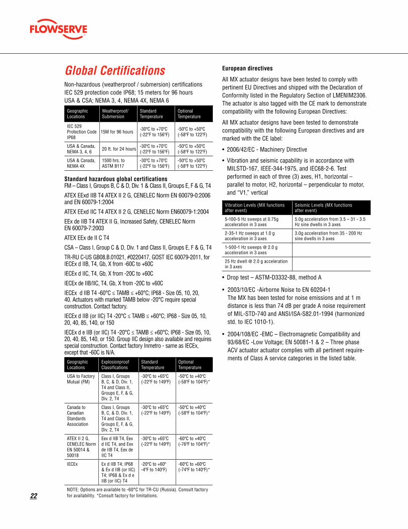
Global Certifications Non-hazardous (weatherproof / submersion) certifications IEC 529 protection code IP68; 15 meters for 96 hours USA & CSA; NEMA 3, 4, NEMA 4X, NEMA 6
Geographic Locations
Weatherproof/Submersion
Standard Temperature
Optional Temperature
IEC 529 Protection Code IP68
15M for 96 hours -30ºC to +70ºC (-22ºF to 156ºF)
-50ºC to +50ºC (-58ºF to 122ºF)
USA & Canada, NEMA 3, 4, 6 20 ft. for 24 hours -30ºC to +70ºC
(-22ºF to 156ºF)-50ºC to +50ºC (-58ºF to 122ºF)
USA & Canada, NEMA 4X
1500 hrs. to ASTM B117
-30ºC to +70ºC (-22ºF to 156ºF)
-50ºC to +50ºC (-58ºF to 122ºF)
Standard hazardous global certifications FM – Class I, Groups B, C & D, Div. 1 & Class II, Groups E, F & G, T4
ATEX EExd IIB T4 ATEX II 2 G, CENELEC Norm EN 60079-0:2006 and EN 60079-1:2004
ATEX EExd IIC T4 ATEX II 2 G, CENELEC Norm EN60079-1:2004
EEx de IIB T4 ATEX II G, Increased Safety, CENELEC Norm EN 60079-7:2003
ATEX EEx de II C T4
CSA – Class I, Group C & D, Div. 1 and Class II, Groups E, F & G, T4
TR-RU C-US GB08.B.01021, #0220417, GOST IEC 60079-2011, for IECEx d IIB, T4, Gb, X from -60C to +60C
IECEx d IIC, T4, Gb, X from -20C to +60C
IECEx de IIB/IIC, T4, Gb, X from -20C to +60C
IECEx d IIB T4 -60°C ≤ TAMB ≤ +60°C; IP68 - Size 05, 10, 20, 40. Actuators with marked TAMB below -20°C require special construction. Contact factory.
IECEx d IIB (or IIC) T4 -20°C ≤ TAMB ≤ +60°C; IP68 - Size 05, 10, 20, 40, 85, 140, or 150
IECEx d e IIB (or IIC) T4 -20°C ≤ TAMB ≤ +60°C; IP68 - Size 05, 10, 20, 40, 85, 140, or 150. Group IIC design also available and requires special construction. Contact factory Inmetro - same as IECEx, except that -60C is N/A.
Geographic Locations
Explosionproof Classifications
Standard Temperature
Optional Temperature
USA to Factory Mutual (FM)
Class I, Groups B, C, & D, Div. 1, T4 and Class II, Groups E, F, & G, Div. 2, T4
-30ºC to +65ºC (-22ºF to 149ºF)
-50ºC to +40ºC (-58ºF to 104ºF)*
Canada to Canadian Standards Association
Class I, Groups B, C, & D, Div. 1, T4 and Class II, Groups E, F, & G, Div. 2, T4
-30ºC to +65ºC (-22ºF to 149ºF)
-50ºC to +40ºC (-58ºF to 104ºF)*
ATEX II 2 G, CENELEC Norm EN 50014 & 50018
Eex d IIB T4, Eex d IIC T4, and Eex de IIB T4, Eex de IIC T4
-30ºC to +65ºC (-22ºF to 149ºF)
-60ºC to +40ºC (-76ºF to 104ºF)*
IECEx Ex d IIB T4; IP68 & Ex d IIB (or IIC) T4; IP68 & Ex d e IIB (or IIC) T4
-20ºC to +60º -4ºF to 140ºF)
-60ºC to +60ºC (-74ºF to 140ºF)*
NOTE: Options are available to -60°C for TR-CU (Russia). Consult factory for availability. *Consult factory for limitations.
European directives
All MX actuator designs have been tested to comply with pertinent EU Directives and shipped with the Declaration of Conformity listed in the Regulatory Section of LMENIM2306. The actuator is also tagged with the CE mark to demonstrate compatibility with the following European Directives:
All MX actuator designs have been tested to demonstrate compatibility with the following European directives and are marked with the CE label:
• 2006/42/EC - Machinery Directive
• Vibration and seismic capability is in accordance with MILSTD-167, IEEE-344-1975, and IEC68-2-6. Test performed in each of three (3) axes, H1, horizontal – parallel to motor, H2, horizontal – perpendicular to motor, and “V1,” vertical
Vibration Levels (MX functions after event)
Seismic Levels (MX functions after event)
5-100-5 Hz sweeps at 0.75g acceleration in 3 axes
5.0g acceleration from 3.5 – 31 - 3.5 Hz sine dwells in 3 axes
2-35-1 Hz sweeps at 1.0 g acceleration in 3 axes
3.0g acceleration from 35 - 200 Hz sine dwells in 3 axes
1-500-1 Hz sweeps @ 2.0 g acceleration in 3 axes
25 Hz dwell @ 2.0 g acceleration in 3 axes
• Drop test – ASTM-D3332-88, method A
• 2003/10/EC -Airborne Noise to EN 60204-1 The MX has been tested for noise emissions and at 1 m distance is less than 74 dB per grade A noise requirement of MIL-STD-740 and ANSI/ISA-S82.01-1994 (harmonized std. to IEC 1010-1).
• 2004/108/EC -EMC – Electromagnetic Compatibility and 93/68/EC -Low Voltage; EN 50081-1 & 2 – Three phase ACV actuator actuator complies with all pertinent require-ments of Class A service categories in the listed table.
flowserve.com
23
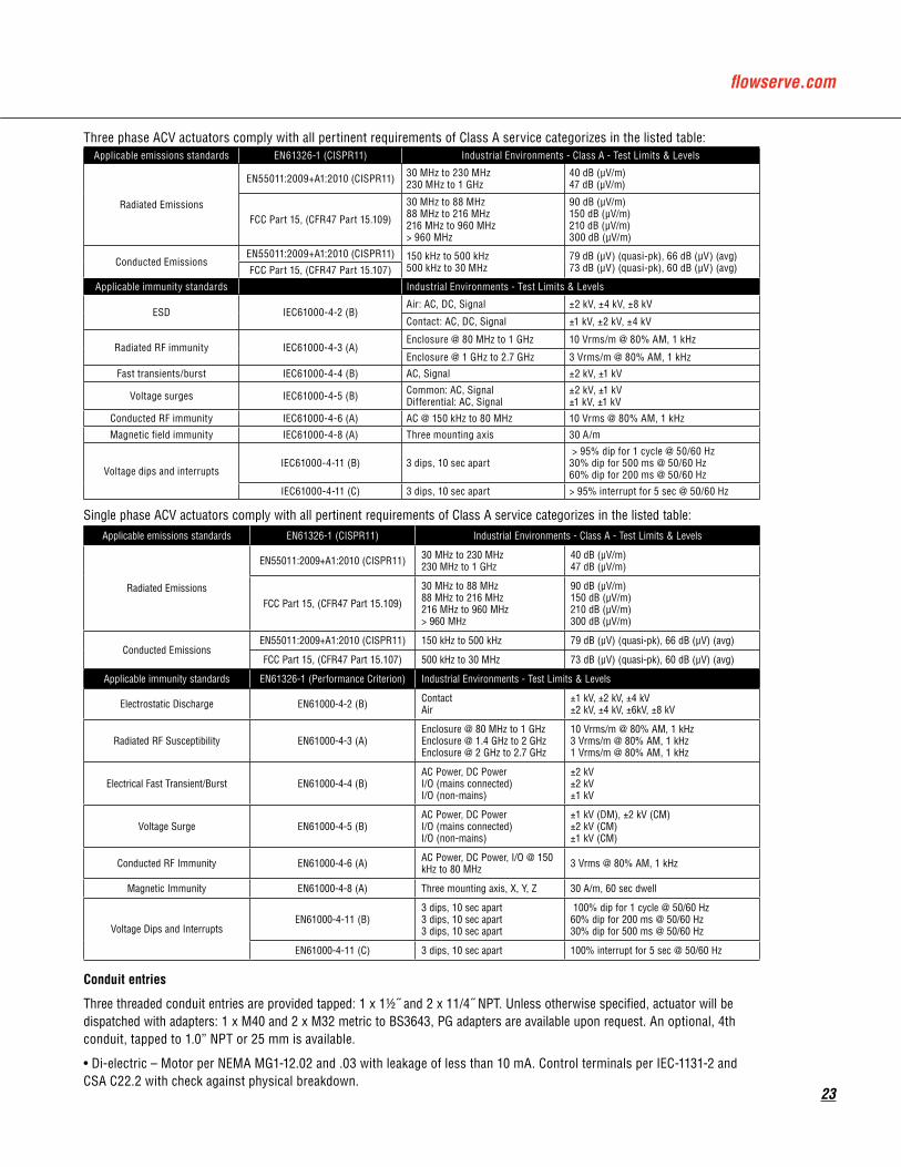
Three phase ACV actuators comply with all pertinent requirements of Class A service categorizes in the listed table: Applicable emissions standards EN61326-1 (CISPR11) Industrial Environments - Class A - Test Limits & Levels
Radiated Emissions
EN55011:2009+A1:2010 (CISPR11) 30 MHz to 230 MHz230 MHz to 1 GHz
40 dB (μV/m)47 dB (μV/m)
FCC Part 15, (CFR47 Part 15.109)
30 MHz to 88 MHz88 MHz to 216 MHz216 MHz to 960 MHz> 960 MHz
90 dB (μV/m)150 dB (μV/m)210 dB (μV/m)300 dB (μV/m)
Conducted Emissions EN55011:2009+A1:2010 (CISPR11) 150 kHz to 500 kHz
500 kHz to 30 MHz79 dB (μV) (quasi-pk), 66 dB (μV) (avg)73 dB (μV) (quasi-pk), 60 dB (μV) (avg)FCC Part 15, (CFR47 Part 15.107)
Applicable immunity standards Industrial Environments - Test Limits & Levels
ESD IEC61000-4-2 (B)Air: AC, DC, Signal ±2 kV, ±4 kV, ±8 kV
Contact: AC, DC, Signal ±1 kV, ±2 kV, ±4 kV
Radiated RF immunity IEC61000-4-3 (A)Enclosure @ 80 MHz to 1 GHz 10 Vrms/m @ 80% AM, 1 kHz
Enclosure @ 1 GHz to 2.7 GHz 3 Vrms/m @ 80% AM, 1 kHz
Fast transients/burst IEC61000-4-4 (B) AC, Signal ±2 kV, ±1 kV
Voltage surges IEC61000-4-5 (B) Common: AC, SignalDifferential: AC, Signal
±2 kV, ±1 kV±1 kV, ±1 kV
Conducted RF immunity IEC61000-4-6 (A) AC @ 150 kHz to 80 MHz 10 Vrms @ 80% AM, 1 kHz
Magnetic field immunity IEC61000-4-8 (A) Three mounting axis 30 A/m
Voltage dips and interrupts IEC61000-4-11 (B) 3 dips, 10 sec apart
> 95% dip for 1 cycle @ 50/60 Hz30% dip for 500 ms @ 50/60 Hz60% dip for 200 ms @ 50/60 Hz
IEC61000-4-11 (C) 3 dips, 10 sec apart > 95% interrupt for 5 sec @ 50/60 Hz
Single phase ACV actuators comply with all pertinent requirements of Class A service categorizes in the listed table:Applicable emissions standards EN61326-1 (CISPR11) Industrial Environments - Class A - Test Limits & Levels
Radiated Emissions
EN55011:2009+A1:2010 (CISPR11) 30 MHz to 230 MHz230 MHz to 1 GHz
40 dB (μV/m)47 dB (μV/m)
FCC Part 15, (CFR47 Part 15.109)
30 MHz to 88 MHz88 MHz to 216 MHz216 MHz to 960 MHz> 960 MHz
90 dB (μV/m)150 dB (μV/m)210 dB (μV/m)300 dB (μV/m)
Conducted Emissions EN55011:2009+A1:2010 (CISPR11) 150 kHz to 500 kHz 79 dB (μV) (quasi-pk), 66 dB (μV) (avg)
FCC Part 15, (CFR47 Part 15.107) 500 kHz to 30 MHz 73 dB (μV) (quasi-pk), 60 dB (μV) (avg)
Applicable immunity standards EN61326-1 (Performance Criterion) Industrial Environments - Test Limits & Levels
Electrostatic Discharge EN61000-4-2 (B) ContactAir
±1 kV, ±2 kV, ±4 kV±2 kV, ±4 kV, ±6kV, ±8 kV
Radiated RF Susceptibility EN61000-4-3 (A)Enclosure @ 80 MHz to 1 GHzEnclosure @ 1.4 GHz to 2 GHzEnclosure @ 2 GHz to 2.7 GHz
10 Vrms/m @ 80% AM, 1 kHz3 Vrms/m @ 80% AM, 1 kHz1 Vrms/m @ 80% AM, 1 kHz
Electrical Fast Transient/Burst EN61000-4-4 (B)AC Power, DC PowerI/O (mains connected)I/O (non-mains)
±2 kV±2 kV±1 kV
Voltage Surge EN61000-4-5 (B)AC Power, DC PowerI/O (mains connected)I/O (non-mains)
±1 kV (DM), ±2 kV (CM)±2 kV (CM)±1 kV (CM)
Conducted RF Immunity EN61000-4-6 (A) AC Power, DC Power, I/O @ 150 kHz to 80 MHz 3 Vrms @ 80% AM, 1 kHz
Magnetic Immunity EN61000-4-8 (A) Three mounting axis, X, Y, Z 30 A/m, 60 sec dwell
Voltage Dips and InterruptsEN61000-4-11 (B)
3 dips, 10 sec apart3 dips, 10 sec apart3 dips, 10 sec apart
100% dip for 1 cycle @ 50/60 Hz60% dip for 200 ms @ 50/60 Hz30% dip for 500 ms @ 50/60 Hz
EN61000-4-11 (C) 3 dips, 10 sec apart 100% interrupt for 5 sec @ 50/60 Hz
Conduit entries
Three threaded conduit entries are provided tapped: 1 x 11/2˝ and 2 x 11/4˝ NPT. Unless otherwise specified, actuator will be dispatched with adapters: 1 x M40 and 2 x M32 metric to BS3643, PG adapters are available upon request. An optional, 4th conduit, tapped to 1.0” NPT or 25 mm is available.
• Di-electric – Motor per NEMA MG1-12.02 and .03 with leakage of less than 10 mA. Control terminals per IEC-1131-2 and CSA C22.2 with check against physical breakdown.

flowserve.com
Flowserve Corporation has established industry leadership in the design and manufacture of its products. When properly selected, this Flowserve product is designed to perform its intended function safely during its useful life. However, the purchaser or user of Flowserve products should be aware that Flowserve products might be used in numerous applications under a wide variety of industrial service conditions. Although Flowserve can (and often does) provide general guidelines, it cannot provide specific data and warnings for all possible applications. The purchaser/user must therefore assume the ultimate responsibility for the proper sizing and selection, installation, operation, and maintenance of Flowserve products. The purchaser/user should read and understand the Installation Operation Maintenance (IOM) instructions included with the product, and train its employees and contractors in the safe use of Flowserve products in connection with the specific application.
While the information and specifications contained in this literature are believed to be accurate, they are supplied for informative purposes only and should not be considered certified or as a guarantee of satisfactory results by reliance thereon. Nothing contained herein is to be construed as a warranty or guarantee, express or implied, regarding any matter with respect to this product. Because Flowserve is continually improving and upgrading its product design, the specifications, dimensions and information contained herein are subject to change without notice. Should any question arise concerning these provisions, the purchaser/user should contact Flowserve Corporation at any one of its worldwide operations or offices.
© 2016 Flowserve Corporation, Irving, Texas, USA. Flowserve is a registered trademark of Flowserve Corporation.
To find your local Flowserve representative:
For more information about Flowserve Corporation, visit www.flowserve.com or call USA 1 800 225 6989
FCD LMENBR2302-06-AQ Printed in USA.
Flowserve Corporation
United StatesFlowserve Limitorque5114 Woodall Road P.O. Box 11318Lynchburg, VA 24506-1318Phone: 434-528-4400Facsimile: 434-845-9736
SingaporeFlowserve Limitorque12, Tuas Avenue 20Singapore 638824Phone: 65-6868-4628Facsimile: 65-6862-4940
ChinaLimitorque Beijing, Pte., Ltd.RM A1/A222/F, East Area, Hanwei PlazaNo. 7 Guanghua Road, Chaoyang DistrictBeijing 100004, Peoples Republic of ChinaPhone: 86-10-5921-0606Facsimile: 86-10-6561-2702
IndiaFlowserve Limitorque, Office A, 7th Floor, Plot No 32A & B, Ambit IT Park, Ambit IT Park Road, Ambattur Industrial Estate, Chennai – 600058 Phone: 91-44-2432-8755 & 91-44-2432-4801 Facsimile: 91-44-2432-8754
ItalyFlowserve LimitorqueVia Rio Vallone 1720883 Mezzago MBItalyPhone: 39-039-620601Facsimile: 39-039-62060 213