limits & fits · shaft size varies according to the type of fit. c t i basic size hole basis...
TRANSCRIPT

Limits & Fits
Explain the necessity for tolerancing.
Identify the symbols used for fundamental deviation.
Identify the numbers used for grades of tolerances.
Select fits for mating components.
Translate limits and fits symbols to engineering drawings using BS4500A.
At the end of this presentation, thestudents should be able to :

• Exact size is impossible to achieve.
• Establish boundaries within which deviation from perfect form is allowed YET still fulfil its design intent.
• Enable interchangeability of engineering components during assembly.
1. Why study Limits & Fits ?
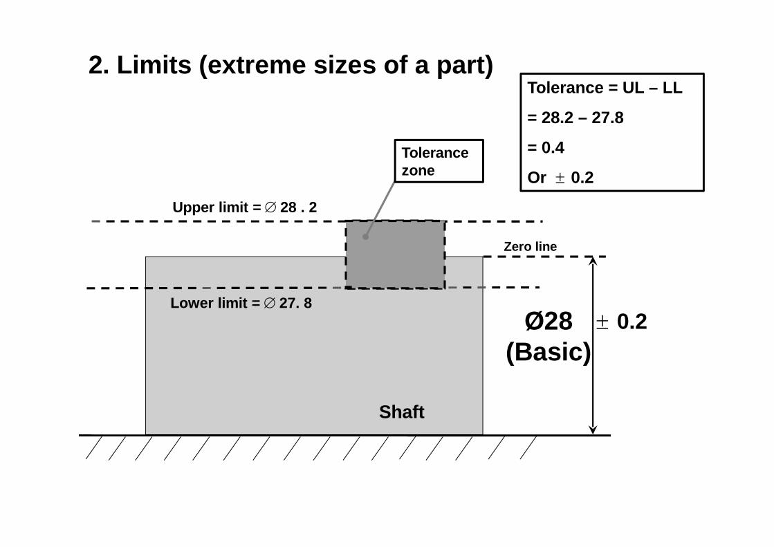
Lower limit = 27. 8 0.2
Upper limit = 28 . 2
Shaft
2. Limits (extreme sizes of a part)
Tolerance zone
Tolerance = UL – LL
= 28.2 – 27.8
= 0.4
Or 0.2
Ø28(Basic)
Zero line
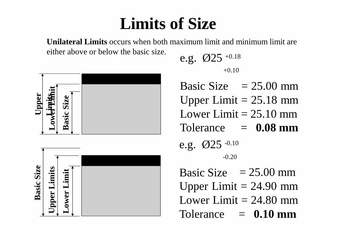
Limits of SizeUnilateral Limits occurs when both maximum limit and minimum limit areeither above or below the basic size.
Upp
er
Low
L erim L
i it msit
Bas
icSi
zee.g. Ø25 +0.18
+0.10
Basic Size = 25.00 mmUpper Limit = 25.18 mmLower Limit = 25.10 mmTolerancee.g. Ø25 -0.10
-0.20
Basic Size
= 0.08 mm
Bas
icSi
ze
Upp
erL
imits
Low
erL
imit = 25.00 mm
Upper Limit = 24.90 mmLower Limit = 24.80 mmTolerance = 0.10 mm
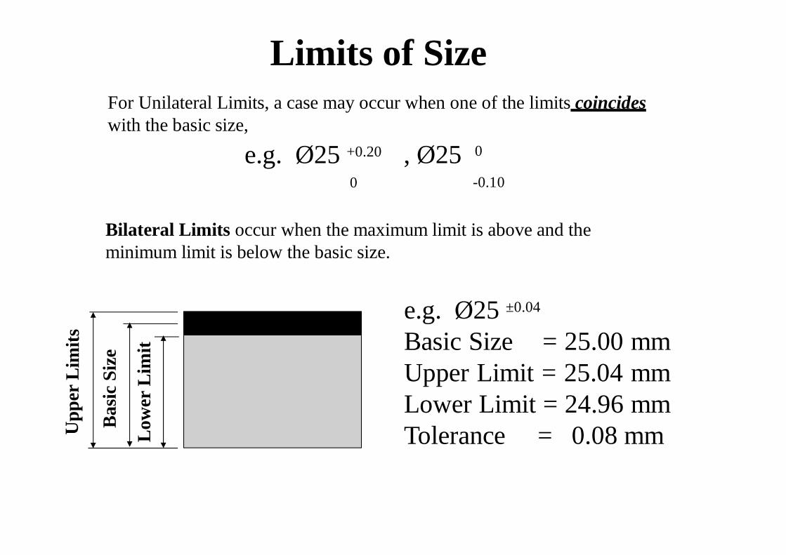
Limits of SizeFor Unilateral Limits, a case may occur when one of the limits coincideswith the basic size,
e.g. Ø25 +0.20 , Ø250
0
-0.10
Bas
icSi
ze
Low
erL
imit
Upp
erL
imits
Bilateral Limits occur when the maximum limit is above and theminimum limit is below the basic size.
e.g. Ø25 ±0.04
Basic Size = 25.00 mmUpper Limit = 25.04 mmLower Limit = 24.96 mmTolerance = 0.08 mm
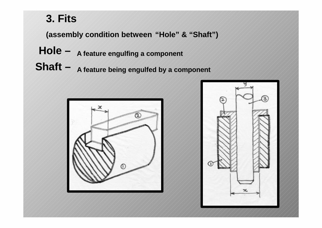
3. Fits(assembly condition between “Hole” & “Shaft”)
Hole –Shaft –
A feature engulfing a component
A feature being engulfed by a component
Hole
Shaft
Min C Max C
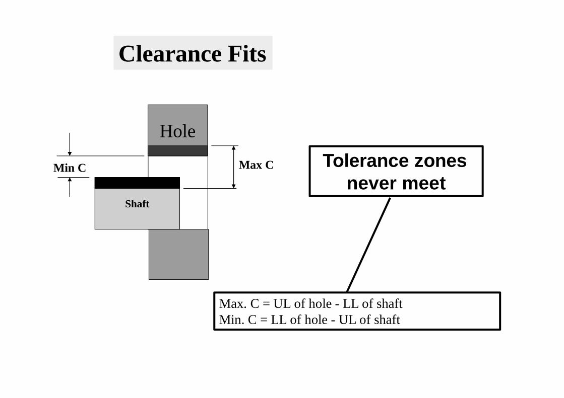
Clearance Fits
Tolerance zones never meet
Max. C = UL of hole - LL of shaftMin. C = LL of hole - UL of shaft
Shaft Min I
Max I
Hole
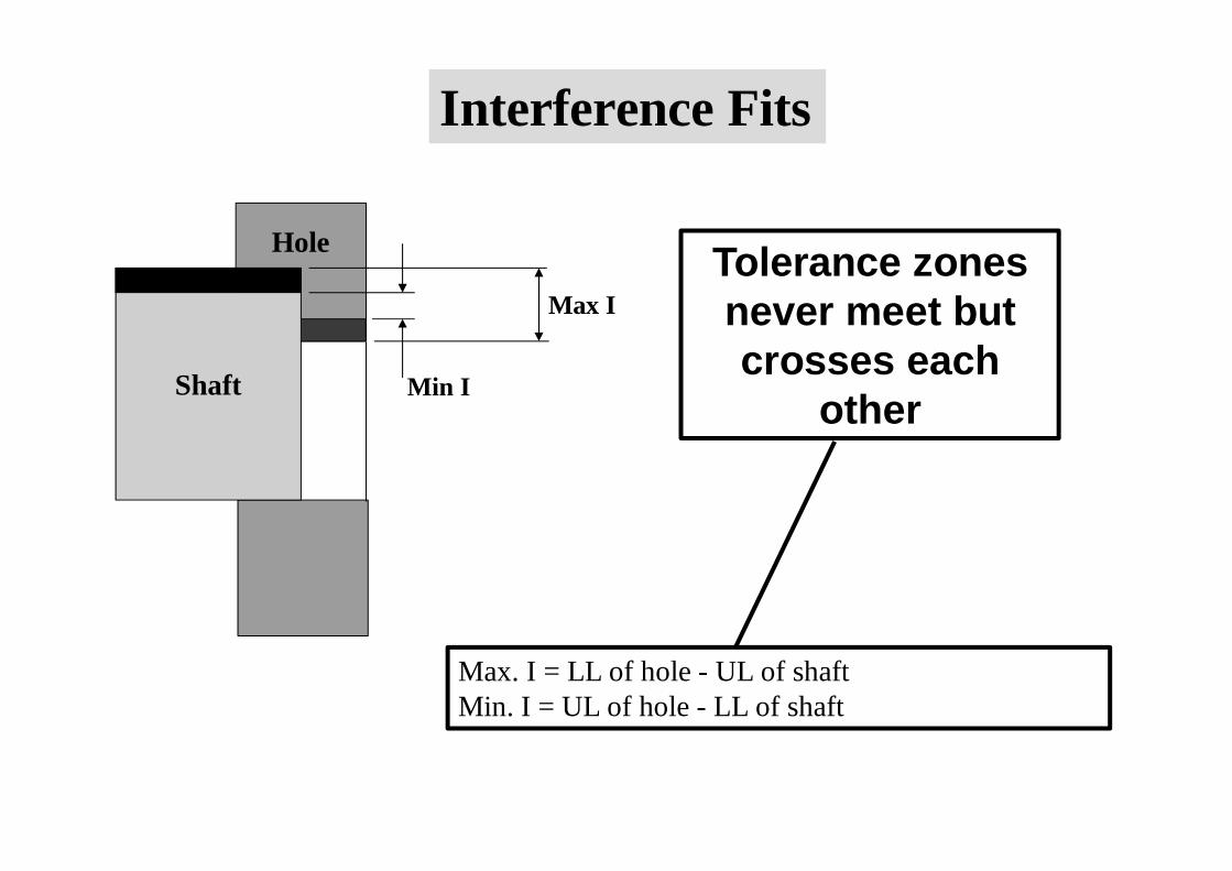
Interference Fits
Tolerance zones never meet butcrosses each
other
Max. I = LL of hole - UL of shaftMin. I = UL of hole - LL of shaft
ShaftMax I
Hole
Max C
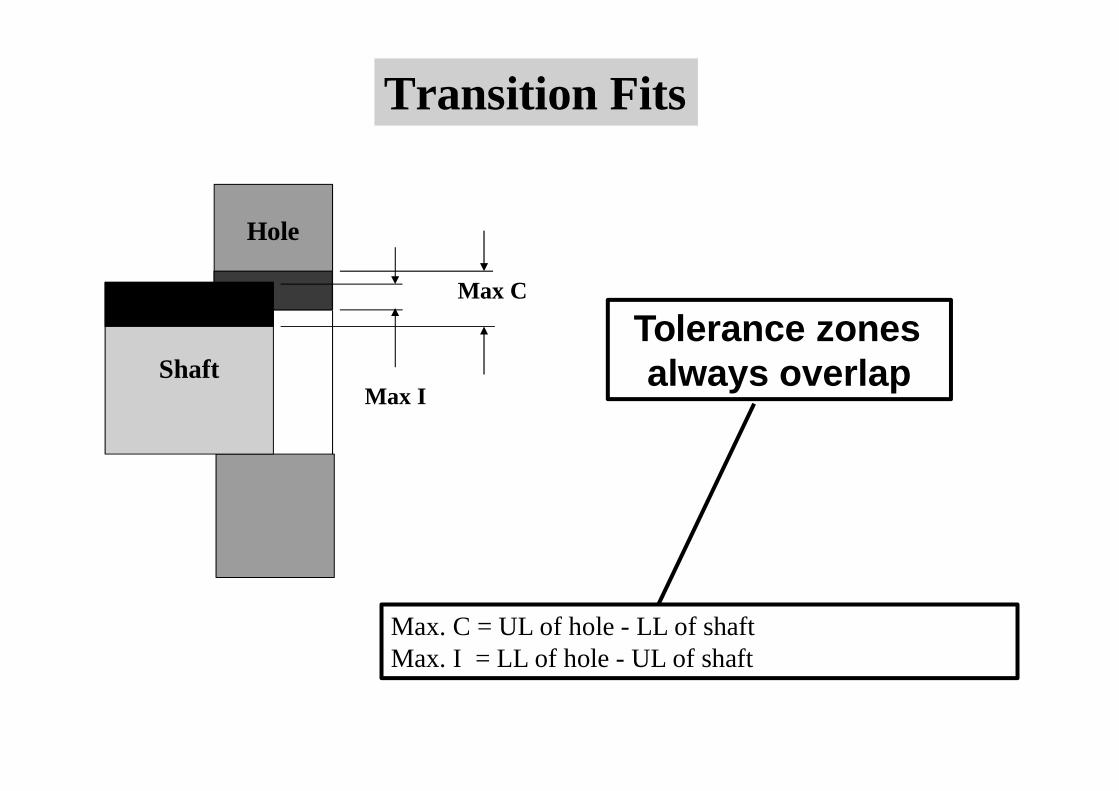
Transition Fits
Tolerance zones always overlap
Max. C = UL of hole - LL of shaftMax. I = LL of hole - UL of shaft
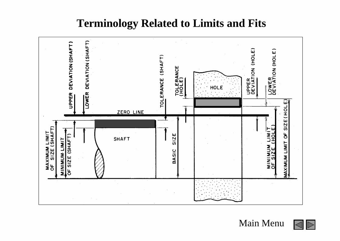
Terminology Related to Limits and Fits
Main Menu
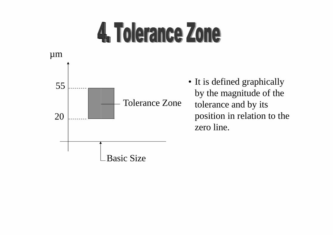
• It is defined graphically by the magnitude of the tolerance and by its position in relation to thezero line.
Tolerance Zone
Basic Size
µm
55
20
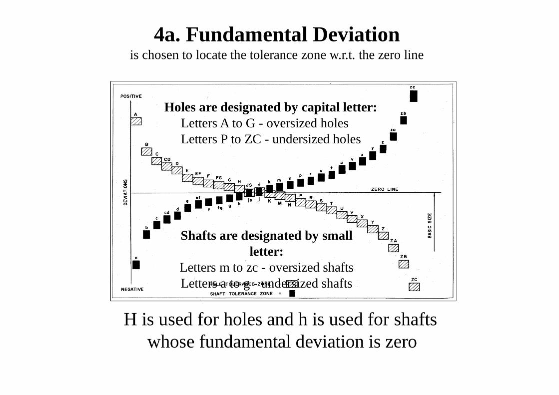
4a. Fundamental Deviationis chosen to locate the tolerance zone w.r.t. the zero line
Holes are designated by capital letter: Letters A to G - oversized holes Letters P to ZC - undersized holes
Shafts are designated by smallletter:
Letters m to zc - oversized shafts Letters a to g - undersized shafts
H is used for holes and h is used for shafts whose fundamental deviation is zero
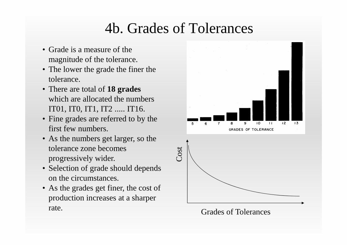
4b. Grades of Tolerances
Grades of Tolerances
Cos
t
• Grade is a measure of themagnitude of the tolerance.
• The lower the grade the finer thetolerance.
• There are total of 18 grades which are allocated the numbersIT01, IT0, IT1, IT2 ..... IT16.
• Fine grades are referred to by thefirst few numbers.
• As the numbers get larger, so thetolerance zone becomes progressively wider.
• Selection of grade should depends on the circumstances.
• As the grades get finer, the cost of production increases at a sharperrate.
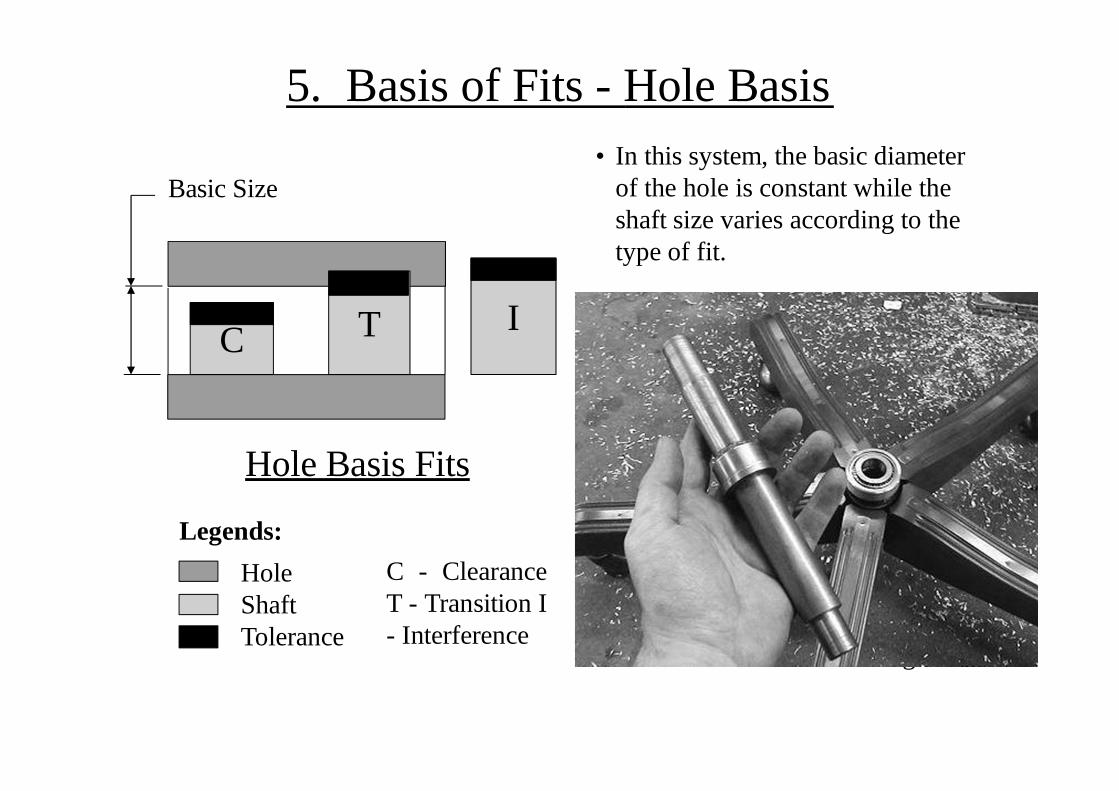
5. Basis of Fits - Hole Basis• In this system, the basic diameter
of the hole is constant while theshaft size varies according to thetype of fit.
C T I
Basic Size
Hole Basis Fits
Legends:C - ClearanceT - Transition I- Interference
HoleShaftTolerance
• This system leads to greater economy of production, as a singledrill or reamer size can be used to produce a variety of fits by merely altering the shaft limits.
• The shaft can be accurately produced to size by turning andgrinding.
• Generally it is usual to recommend hole-base fits, except wheretemperature may have adetrimental effect on large sizes.
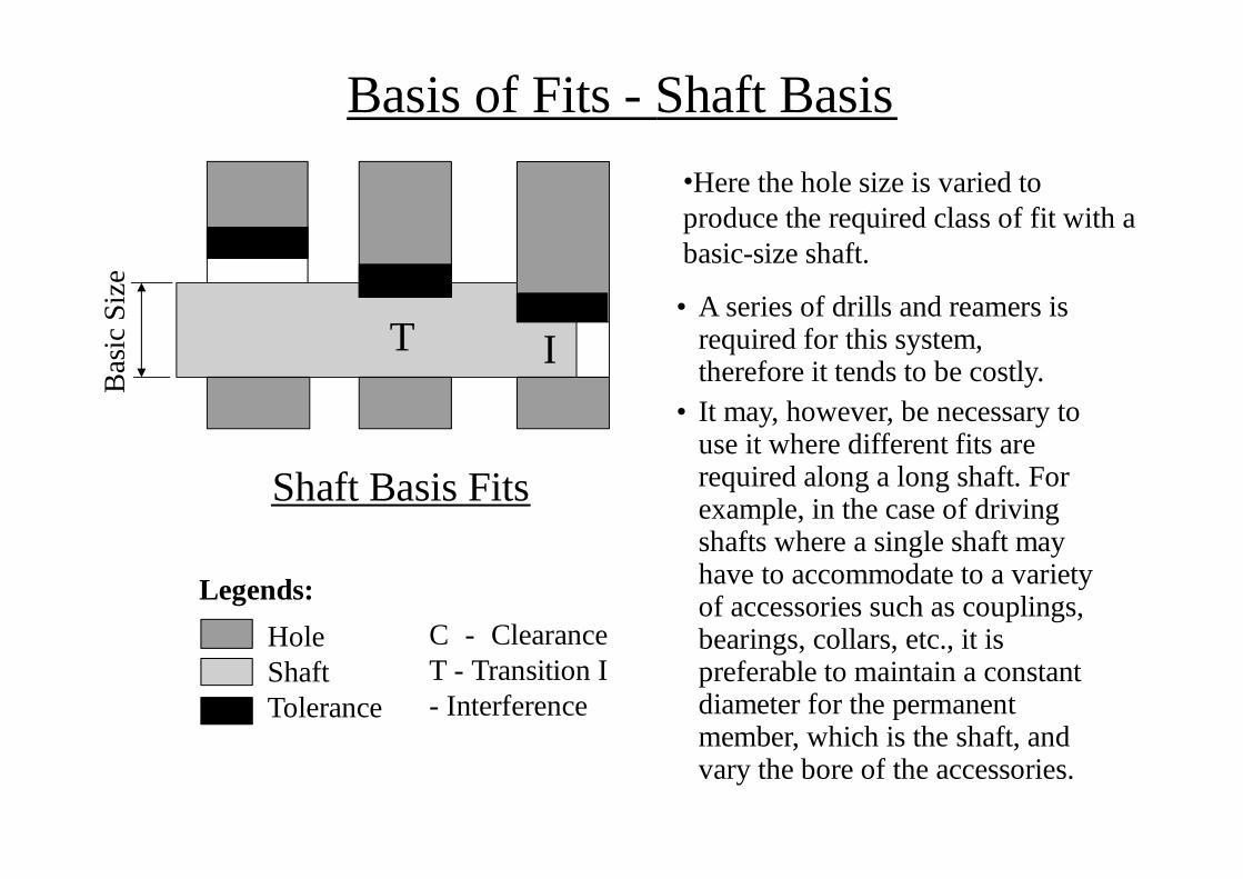
Basis of Fits - Shaft BasisB
asic
Siz
e
I
HoleShaftTolerance
C - ClearanceT - Transition I- Interference
•Here the hole size is varied to produce the required class of fit with abasic-size shaft.
• A series of drills and reamers is required for this system, therefore it tends to be costly.
• It may, however, be necessary to use it where different fits are required along a long shaft. For example, in the case of drivingshafts where a single shaft mayhave to accommodate to a variety of accessories such as couplings, bearings, collars, etc., it is preferable to maintain a constantdiameter for the permanentmember, which is the shaft, and vary the bore of the accessories.
T
Shaft Basis Fits
Legends:
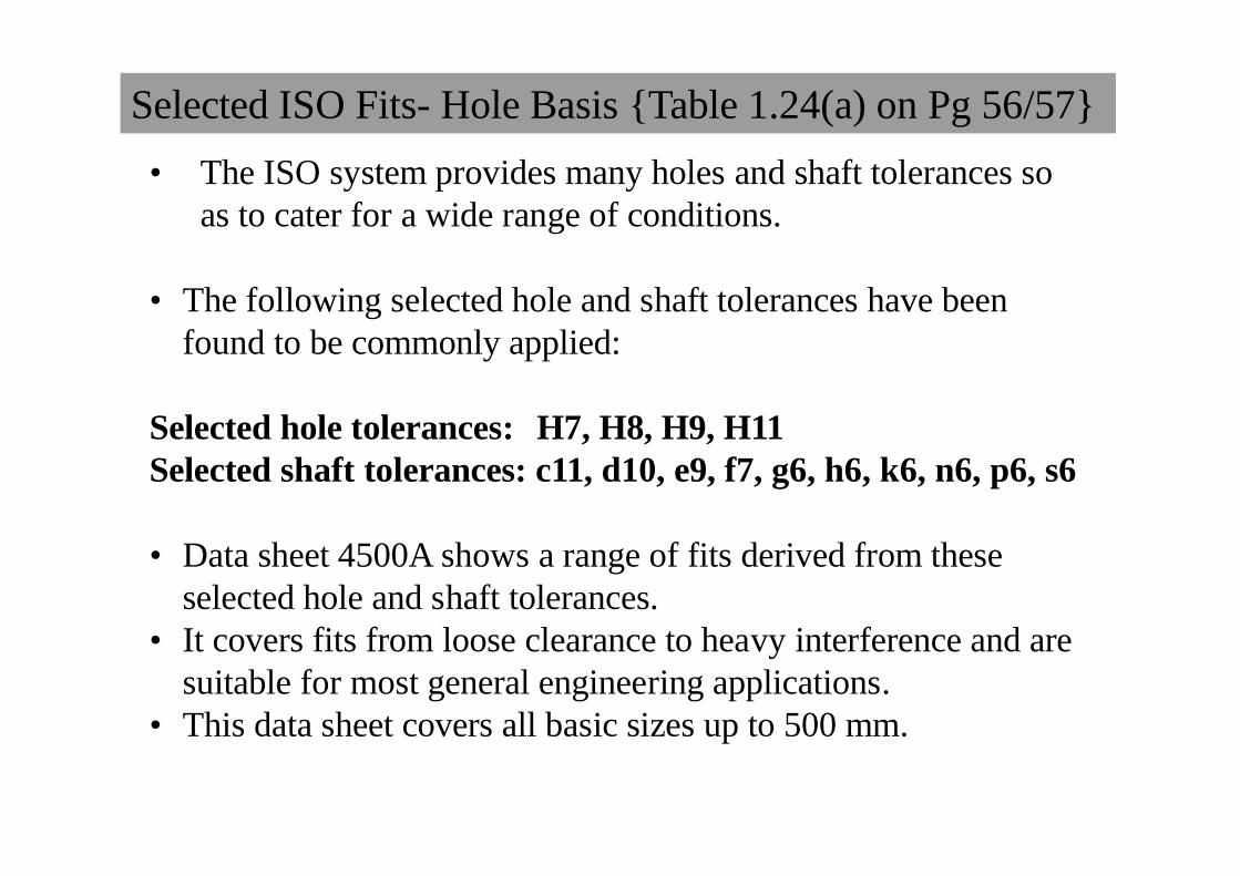
Selected ISO Fits- Hole Basis {Table 1.24(a) on Pg 56/57}• The ISO system provides many holes and shaft tolerances so
as to cater for a wide range of conditions.
• The following selected hole and shaft tolerances have beenfound to be commonly applied:
Selected hole tolerances: H7, H8, H9, H11Selected shaft tolerances: c11, d10, e9, f7, g6, h6, k6, n6, p6, s6
• Data sheet 4500A shows a range of fits derived from theseselected hole and shaft tolerances.
• It covers fits from loose clearance to heavy interference and are suitable for most general engineering applications.
• This data sheet covers all basic sizes up to 500 mm.
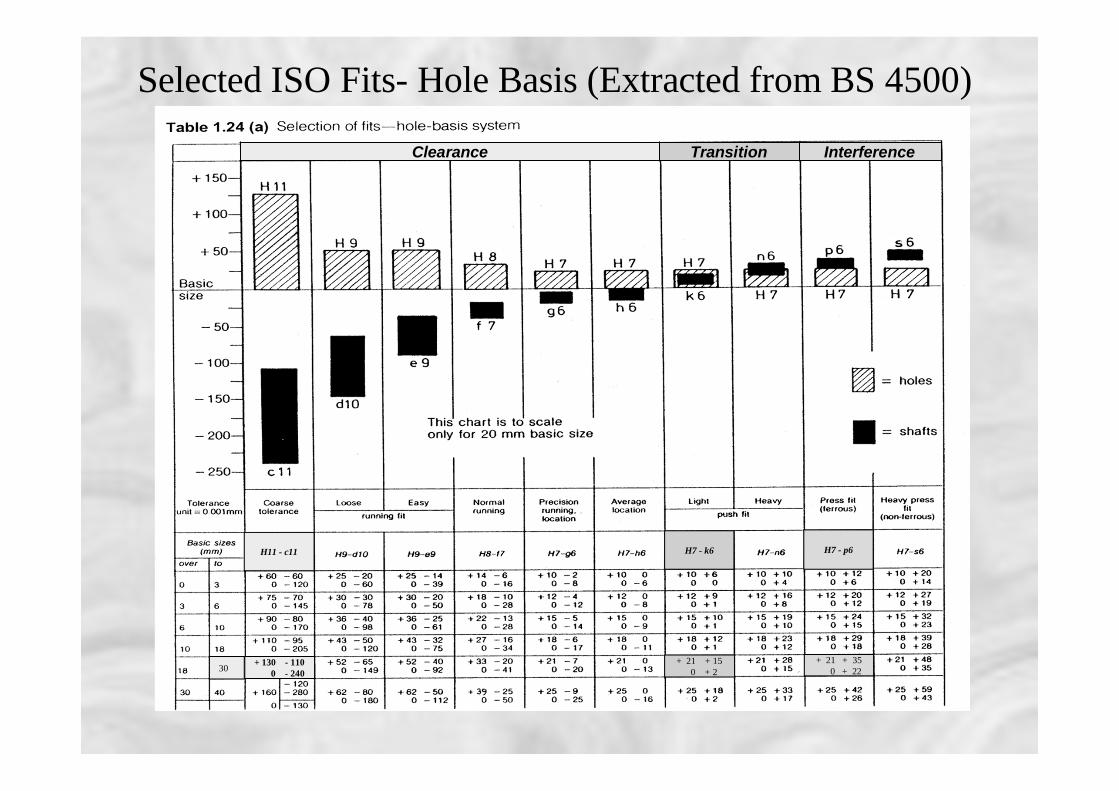
Selected ISO Fits- Hole Basis (Extracted from BS 4500)
+ 130 - 1100 - 240
+ 21 + 350 + 22
+ 21 + 150 + 2
H11 - c11 H7 - k6 H7 - p6
30
Clearance Transition Interference
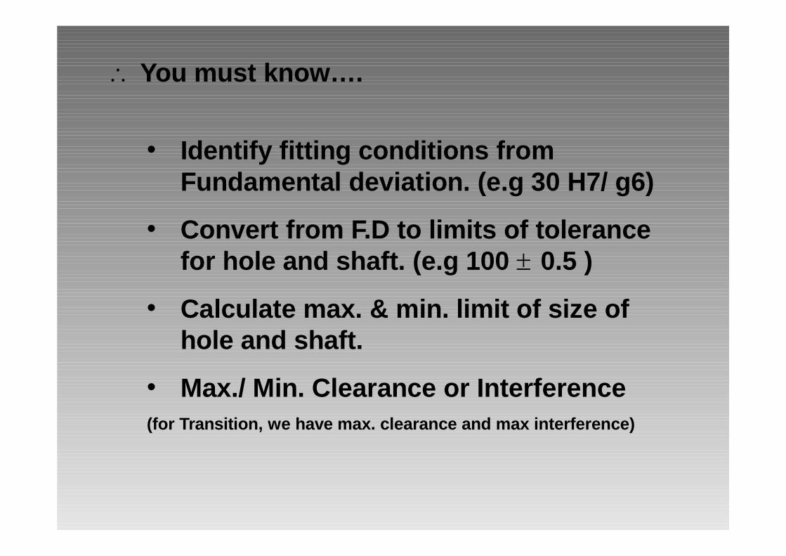
• Identify fitting conditions fromFundamental deviation. (e.g 30 H7/ g6)
• Convert from F.D to limits of tolerancefor hole and shaft. (e.g 100 0.5 )
• Calculate max. & min. limit of size ofhole and shaft.
• Max./ Min. Clearance or Interference(for Transition, we have max. clearance and max interference)
You must know….
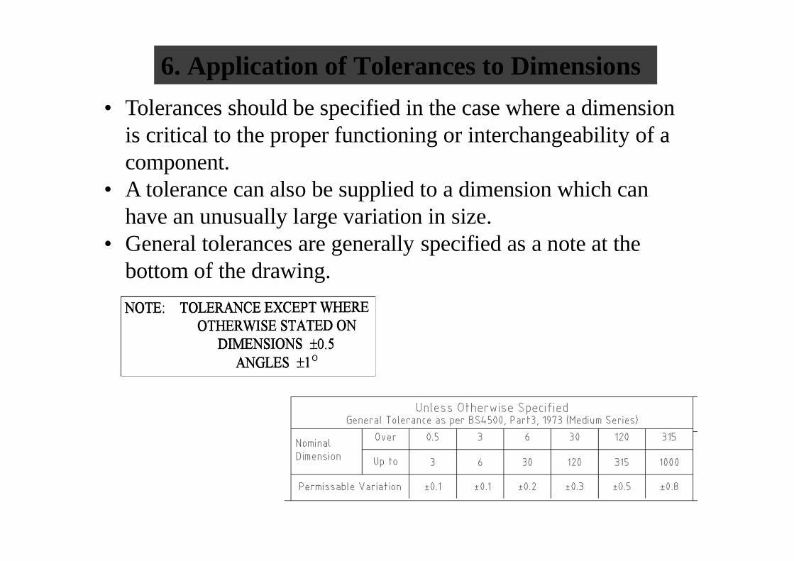
6. Application of Tolerances to Dimensions• Tolerances should be specified in the case where a dimension
is critical to the proper functioning or interchangeability of acomponent.
• A tolerance can also be supplied to a dimension which can have an unusually large variation in size.
• General tolerances are generally specified as a note at the bottom of the drawing.
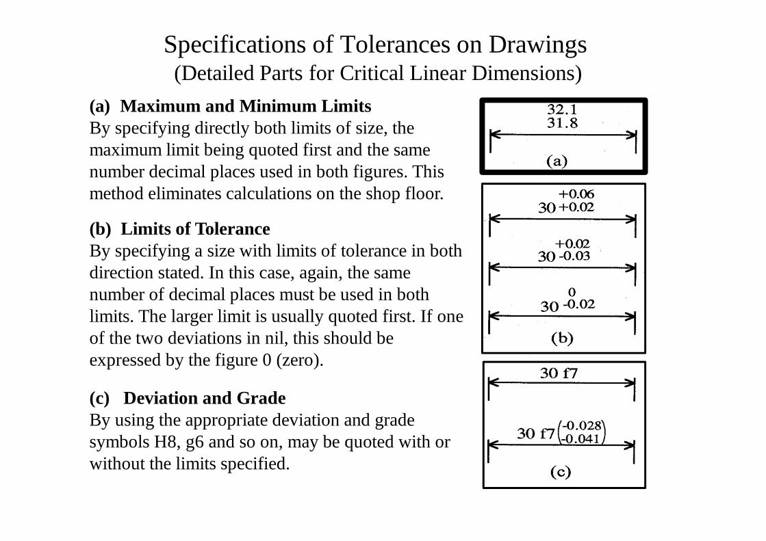
Specifications of Tolerances on Drawings(Detailed Parts for Critical Linear Dimensions)
(a) Maximum and Minimum LimitsBy specifying directly both limits of size, themaximum limit being quoted first and the samenumber decimal places used in both figures. Thismethod eliminates calculations on the shop floor.
(b) Limits of ToleranceBy specifying a size with limits of tolerance in both direction stated. In this case, again, the samenumber of decimal places must be used in both limits. The larger limit is usually quoted first. If oneof the two deviations in nil, this should beexpressed by the figure 0 (zero).
(c) Deviation and GradeBy using the appropriate deviation and gradesymbols H8, g6 and so on, may be quoted with or without the limits specified.
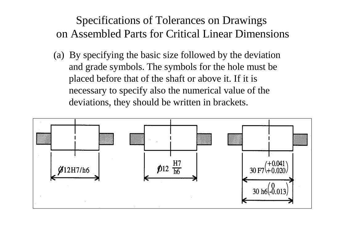
Specifications of Tolerances on Drawingson Assembled Parts for Critical Linear Dimensions
(a) By specifying the basic size followed by the deviation and grade symbols. The symbols for the hole must beplaced before that of the shaft or above it. If it is necessary to specify also the numerical value of the deviations, they should be written in brackets.
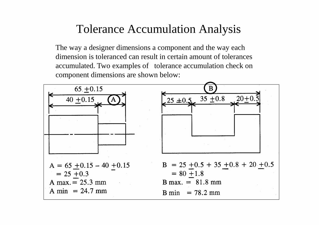
Tolerance Accumulation AnalysisThe way a designer dimensions a component and the way eachdimension is toleranced can result in certain amount of tolerances accumulated. Two examples of tolerance accumulation check on component dimensions are shown below:

Any QuestionsYou have just learnt:
2. Definition of Limits
3. Type of fits
4. Tolerance zone and size
5. Using BS4500 (selection of common fits)
6. Tolerances placement on drawing
7. Accumulation of tolerances