lindapter - beam to beam fixings
DESCRIPTION
Fixings (Clamps) for connecting structural BeamsTRANSCRIPT
Technical Innovationin Steelwork Connection

2
3
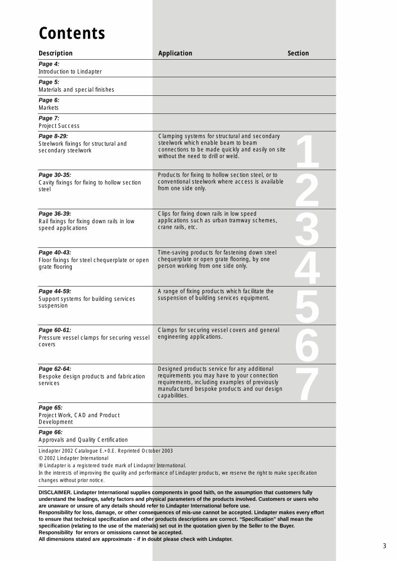
ContentsDescription
Page 4:Introduction to Lindapter
Page 5:Materials and special finishes
Page 6:Markets
Page 7:Project Success
Page 8-29:Steelwork fixings for structural andsecondary steelwork
Page 30-35:Cavity fixings for fixing to hollow sectionsteel
Page 36-39:Rail fixings for fixing down rails in lowspeed applications
Page 40-43:Floor fixings for steel chequerplate or opengrate flooring
Page 44-59:Support systems for building servicessuspension
Page 60-61:Pressure vessel clamps for securing vesselcovers
Page 62-64:Bespoke design products and fabricationservices
Page 65:Project Work, CAD and ProductDevelopment
Page 66:Approvals and Quality Certification
Products for fixing to hollow section steel, or toconventional steelwork where access is availablefrom one side only.
Clips for fixing down rails in low speedapplications such as urban tramway schemes,crane rails, etc.
Time-saving products for fastening down steelchequerplate or open grate flooring, by oneperson working from one side only.
A range of fixing products which facilitate thesuspension of building services equipment.
Clamps for securing vessel covers and generalengineering applications.
Designed products service for any additionalrequirements you may have to your connectionrequirements, including examples of previouslymanufactured bespoke products and our designcapabilities.
Application
Clamping systems for structural and secondarysteelwork which enable beam to beamconnections to be made quickly and easily on sitewithout the need to drill or weld. 1
234567
Section
Lindapter 2002 Catalogue E.+0.E. Reprinted October 2003© 2002 Lindapter International ® Lindapter is a registered trade mark of Lindapter International.In the interests of improving the quality and performance of Lindapter products, we reserve the right to make specificationchanges without prior notice.
DISCLAIMER. Lindapter International supplies components in good faith, on the assumption that customers fullyunderstand the loadings, safety factors and physical parameters of the products involved. Customers or users whoare unaware or unsure of any details should refer to Lindapter International before use.Responsibility for loss, damage, or other consequences of mis-use cannot be accepted. Lindapter makes every effortto ensure that technical specification and other products descriptions are correct. “Specification” shall mean thespecification (relating to the use of the materials) set out in the quotation given by the Seller to the Buyer.Responsibility for errors or omissions cannot be accepted.All dimensions stated are approximate - if in doubt please check with Lindapter.
4
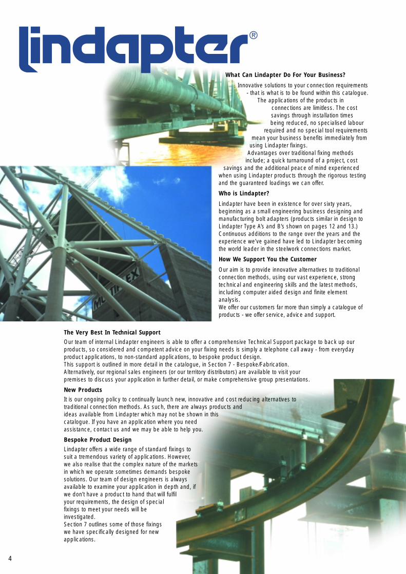
What Can Lindapter Do For Your Business?
Innovative solutions to your connection requirements- that is what is to be found within this catalogue.
The applications of the products inconnections are limitless. The costsavings through installation timesbeing reduced, no specialised labour
required and no special tool requirementsmean your business benefits immediately from
using Lindapter fixings.Advantages over traditional fixing methods
include; a quick turnaround of a project, costsavings and the additional peace of mind experienced
when using Lindapter products through the rigorous testingand the guaranteed loadings we can offer.
Who is Lindapter?
Lindapter have been in existence for over sixty years,beginning as a small engineering business designing andmanufacturing bolt adapters (products similar in design toLindapter Type A’s and B’s shown on pages 12 and 13.)Continuous additions to the range over the years and theexperience we’ve gained have led to Lindapter becomingthe world leader in the steelwork connections market.
How We Support You the Customer
Our aim is to provide innovative alternatives to traditionalconnection methods, using our vast experience, strongtechnical and engineering skills and the latest methods,including computer aided design and finite elementanalysis.We offer our customers far more than simply a catalogue ofproducts - we offer service, advice and support.
The Very Best In Technical SupportOur team of internal Lindapter engineers is able to offer a comprehensive Technical Support package to back up ourproducts, so considered and competent advice on your fixing needs is simply a telephone call away - from everydayproduct applications, to non-standard applications, to bespoke product design.This support is outlined in more detail in the catalogue, in Section 7 - Bespoke/Fabrication.Alternatively, our regional sales engineers (or our territory distributors) are available to visit yourpremises to discuss your application in further detail, or make comprehensive group presentations.
New ProductsIt is our ongoing policy to continually launch new, innovative and cost reducing alternatives totraditional connection methods. As such, there are always products andideas available from Lindapter which may not be shown in thiscatalogue. If you have an application where you needassistance, contact us and we may be able to help you.
Bespoke Product DesignLindapter offers a wide range of standard fixings tosuit a tremendous variety of applications. However,we also realise that the complex nature of the marketsin which we operate sometimes demands bespokesolutions. Our team of design engineers is alwaysavailable to examine your application in depth and, ifwe don’t have a product to hand that will fulfilyour requirements, the design of specialfixings to meet your needs will beinvestigated.Section 7 outlines some of those fixingswe have specifically designed for newapplications.
5
Material A Malleable Iron to BS EN 1562:1997B SG Iron to BS EN 1563:1997 C M.S. Flat Black to BS EN 10025:1993 D Bright Mild Steel Bar to BS 10087:1999 E High Corrosion Resistance Stainless Steel to
BS EN 10088-1F Forged Steel to BS EN 10083-1:1991+ A1:1996 G Steel Strip to BS EN 10132-4: 2000 Grade C70 H Continuously Hot Dip Zinc Coated Steel Strip to
BS EN 10142: 2000 I High Grade Alloy Steel J Steel Strip to BS EN 10111:1998 K Cold Rolled Carbon Steel to BS 5770: Part 2:1981
(1995) L Mild Steel Strip to BS EN 10025:1993 Grade S275 M Galvanised Steel Strip to BS EN 10147: 2000N Mild Steel to BS EN 10027-1 DD 11O Commercial Stainless Steel Strip to BS EN 10088-2P Investment Cast Stainless Steel to BS 3146:1974
(1993) Grade ANC 4A/4BQ Stainless Steel Fastener to BS EN ISO 3506:
1998 Grade A4/70R Cold Rolled Steel Sheet to BS EN 10130: 1991+
A1: 1998 Grade DC 01
Finish 1 Electro Zinc Plated to BS EN 12329: 2000
Grade Fe//Zn5//A (Clear)2 Hot Dip Spun Galvanised to BS EN ISO 1461:
19993 As required 4 Sheradized to BS 4921: 1988 (1994) Class 1
plus additional secondary corrosion protection 500 Hours salt spray capability
5 Continuously Hot Dip Zinc Coated6 Electro Zinc Plated to BS EN 12329: 2000
Grade Fe//Zn5//C (Yellow)7 Electro Zinc Plated to BS EN 12329: 2000
Grade Fe//Zn8//C plus JS 500 Leach and Seal8 Mechanical Galvanised to ASTM B695 Class 50
Specific industries bring with them specific problems - Lindapter can assist in finding solutions to these problems.Expensive hot work permits on offshore and process projects create problems with maintenance and restrictmodifications to plant - benefits of not having to drill or weld eliminate these preclusions. Advantages of on-siteadjustability without coatings being harmed, mean additional costs of re-painting or repairing damaged coatings willnot be accrued.
Lindapter is Committed to Customer ServiceLindapter operates with a company-wide focus on providing the utmost in customer service and we believe that youwill find us accommodating, supportive and providing guidance for all your connection needs. We are alwaysdelighted to hear your comments, both positive and negative, on the service which we offer. Please address yourcommunications for the attention of the Marketing Manager. A copy of our customer service policy is available on request.
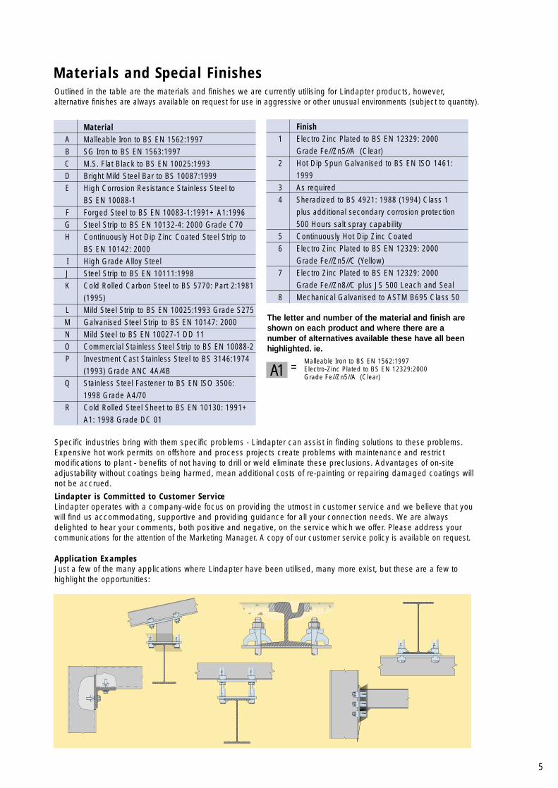
Application ExamplesJust a few of the many applications where Lindapter have been utilised, many more exist, but these are a few tohighlight the opportunities:
The letter and number of the material and finish areshown on each product and where there are anumber of alternatives available these have all beenhighlighted. ie.
Outlined in the table are the materials and finishes we are currently utilising for Lindapter products, however,alternative finishes are always available on request for use in aggressive or other unusual environments (subject to quantity).
A1Malleable Iron to BS EN 1562:1997
= Electro-Zinc Plated to BS EN 12329:2000 Grade Fe//Zn5//A (Clear)
Materials and Special Finishes

Markets
Structural EngineeringLindapter fixings for steelwork are used in construction andrefurbishment projects world-wide, providing both permanent andtemporary fixings without weakening existing structures. The high qualityproducts offer an innovative and cost effective alternative to traditionalconnection methods, and all offer guaranteed load bearing capabilities.Applications include fixing of cladding, steel flooring and temporaryaccess runway beams as well as secondary steelwork installation.
6
The versatility of our product range is underlined by the diversity of the markets in which Lindapter is present. Themain industries are outlined here, although there are applications for Lindapter products in additional markets.
Civil EngineeringLindapter applications include the construction or repair of bridges,usually for road or rail purposes. There are also many uses for the fullproduct range within power stations, water treatment plants, andtunnelling projects.
Building Services Whether fixing to I beams, purlins, hollow section, steel cavities or hollowconcrete, Lindapter has the support fixing to suit. The range is fullytested and has been designed to offer savings in installation time andcosts. Applications include the installation of pipework, HVAC systems,sprinkler systems, electrical equipment and cable trays, ladder rackingand suspended ceilings.
Process/Plant Engineering The full range of Lindapter products is invaluable within the processenvironment including petrochemicals, industrial or agrochemicals, andthe offshore oil and gas industry. They permit connections to be madewithout hot work permits and without damaging protective coatings.Applications include pipe and cable supports, walkway supports,sprinkler installations and secondary steelwork connections.
Materials HandlingLindapter products have a range of applications within the materialshandling industry which include conveyor supports, monorail supports,header steelwork connections and lift installations. Because there is noneed for drilling or welding, temporary or permanent connections can bemade which enable conveyor installations to be re-routed or removedwithout difficulty.
TransportationThe Lindapter range has numerous applications within the transportationindustry. Fast and convenient fixings are available for overhead catenarysystems, trackwork cable troughs, electrification bracketry, stationmonitors, and vehicle trailer sideguards. Lindapter rail fixings are idealfor holding down rails in low speed applications.
7
Project Successes
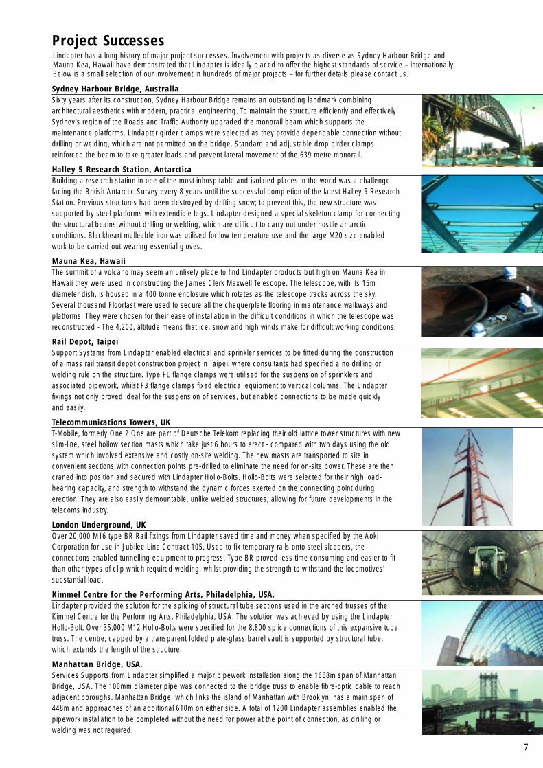
Sydney Harbour Bridge, AustraliaSixty years after its construction, Sydney Harbour Bridge remains an outstanding landmark combiningarchitectural aesthetics with modern, practical engineering. To maintain the structure efficiently and effectivelySydney's region of the Roads and Traffic Authority upgraded the monorail beam which supports themaintenance platforms. Lindapter girder clamps were selected as they provide dependable connection withoutdrilling or welding, which are not permitted on the bridge. Standard and adjustable drop girder clampsreinforced the beam to take greater loads and prevent lateral movement of the 639 metre monorail.
Halley 5 Research Station, AntarcticaBuilding a research station in one of the most inhospitable and isolated places in the world was a challengefacing the British Antarctic Survey every 8 years until the successful completion of the latest Halley 5 ResearchStation. Previous structures had been destroyed by drifting snow; to prevent this, the new structure wassupported by steel platforms with extendible legs. Lindapter designed a special skeleton clamp for connectingthe structural beams without drilling or welding, which are difficult to carry out under hostile antarcticconditions. Blackheart malleable iron was utilised for low temperature use and the large M20 size enabledwork to be carried out wearing essential gloves.
Mauna Kea, HawaiiThe summit of a volcano may seem an unlikely place to find Lindapter products but high on Mauna Kea inHawaii they were used in constructing the James Clerk Maxwell Telescope. The telescope, with its 15mdiameter dish, is housed in a 400 tonne enclosure which rotates as the telescope tracks across the sky.Several thousand Floorfast were used to secure all the chequerplate flooring in maintenance walkways andplatforms. They were chosen for their ease of installation in the difficult conditions in which the telescope wasreconstructed - The 4,200, altitude means that ice, snow and high winds make for difficult working conditions.
Rail Depot, TaipeiSupport Systems from Lindapter enabled electrical and sprinkler services to be fitted during the constructionof a mass rail transit depot construction project in Taipei. where consultants had specified a no drilling orwelding rule on the structure. Type FL flange clamps were utilised for the suspension of sprinklers andassociated pipework, whilst F3 flange clamps fixed electrical equipment to vertical columns. The Lindapterfixings not only proved ideal for the suspension of services, but enabled connections to be made quickly and easily.
Telecommunications Towers, UKT-Mobile, formerly One 2 One are part of Deutsche Telekom replacing their old lattice tower structures with newslim-line, steel hollow section masts which take just 6 hours to erect - compared with two days using the oldsystem which involved extensive and costly on-site welding. The new masts are transported to site inconvenient sections with connection points pre-drilled to eliminate the need for on-site power. These are thencraned into position and secured with Lindapter Hollo-Bolts. Hollo-Bolts were selected for their high load-bearing capacity, and strength to withstand the dynamic forces exerted on the connecting point duringerection. They are also easily demountable, unlike welded structures, allowing for future developments in thetelecoms industry.
London Underground, UKOver 20,000 M16 type BR Rail fixings from Lindapter saved time and money when specified by the AokiCorporation for use in Jubilee Line Contract 105. Used to fix temporary rails onto steel sleepers, theconnections enabled tunnelling equipment to progress. Type BR proved less time consuming and easier to fitthan other types of clip which required welding, whilst providing the strength to withstand the locomotives’substantial load.
Kimmel Centre for the Performing Arts, Philadelphia, USA.Lindapter provided the solution for the splicing of structural tube sections used in the arched trusses of theKimmel Centre for the Performing Arts, Philadelphia, USA. The solution was achieved by using the LindapterHollo-Bolt. Over 35,000 M12 Hollo-Bolts were specified for the 8,800 splice connections of this expansive tubetruss. The centre, capped by a transparent folded plate-glass barrel vault is supported by structural tube,which extends the length of the structure.
Manhattan Bridge, USA.Services Supports from Lindapter simplified a major pipework installation along the 1668m span of ManhattanBridge, USA. The 100mm diameter pipe was connected to the bridge truss to enable fibre-optic cable to reachadjacent boroughs. Manhattan Bridge, which links the island of Manhattan with Brooklyn, has a main span of448m and approaches of an additional 610m on either side. A total of 1200 Lindapter assemblies enabled thepipework installation to be completed without the need for power at the point of connection, as drilling orwelding was not required.
Lindapter has a long history of major project successes. Involvement with projects as diverse as Sydney Harbour Bridge andMauna Kea, Hawaii have demonstrated that Lindapter is ideally placed to offer the highest standards of service – internationally.Below is a small selection of our involvement in hundreds of major projects – for further details please contact us.

8
The Lindapter method of fixing to or from steelwork isthe most adaptable system you will encounter. Theprinciple - which can be applied to any profile ofsteelwork - has been utilised in almost every country inthe world since it’s conception in 1934.
Steelwork fixings are purpose-made malleable ironhook-bolt adapters that can securely grip the flange ofmost standard steel sections. With no need to drill orweld on site because standard components can beassembled simply by the use of spanners, cost ofinstallation is kept to a minimum - a plus point with anyproject. Primarily for secondary steelwork, the fixingsenable beam to beam connections to be made quicklyand easily on site.
The diversity of project applications that can utiliseLindapter steelwork fixings is immense and thefollowing pages illustrate some of the permutations thatare possible. This should give you a comprehension ofthe wide variety of uses these applications could havewithin your projects. The total adjustability andversatility of the complete range of standard productswhich is available means that the possibilities areendless and only compromised by the scope of thedesigners imagination.
However, the main message should be that Lindapteris versatile, with our own design service and a productdevelopment team at your disposal, your connectionobstacles can be overcome.
Steelwork Fixings
Steelwork Fixings ContentsIntroduction to Steelwork Fixings 8Girder Clamp 9Components of a Girder Clamp 10Accessory Index 10Girder Clamp Applications 11Type A - Recessed Fixing 12Type B - Flat Top Fixing 13Type SC - Shackle Clamp 14Type AF - High Friction Clamp 15Type LR - Self Adjusting Clamp 16Type C1 and C2 - Hook Nosed Adapters 17Type D2 - Adjustable Tail Length Fixing 18Type D3 - Adjustable Tail Length Fixing 19Type D1 - Flexible Tail Fixing 20Type E - Threaded Fixing 21Type TRL Clamp 21Type F9 - Flange Clamp 21Type BS - Flat Top Fixing with No Tail 22Type BS - Long Nose version 22Type CW - Clipped Washer 23Type P1 and P2 - Packings 23High Friction Packings 23Type T - Tip 24Type W - Deep Washer 24Type AFW - Adapter Washer for High Friction 24Type FC - Flush Clamp 25Loads and Specifications 26Specifying Your Steelwork Fixings 27Tail Length/Packing Combinations 28Additional Steelwork Applications 29
9
Stee
lwor
k Fi
s
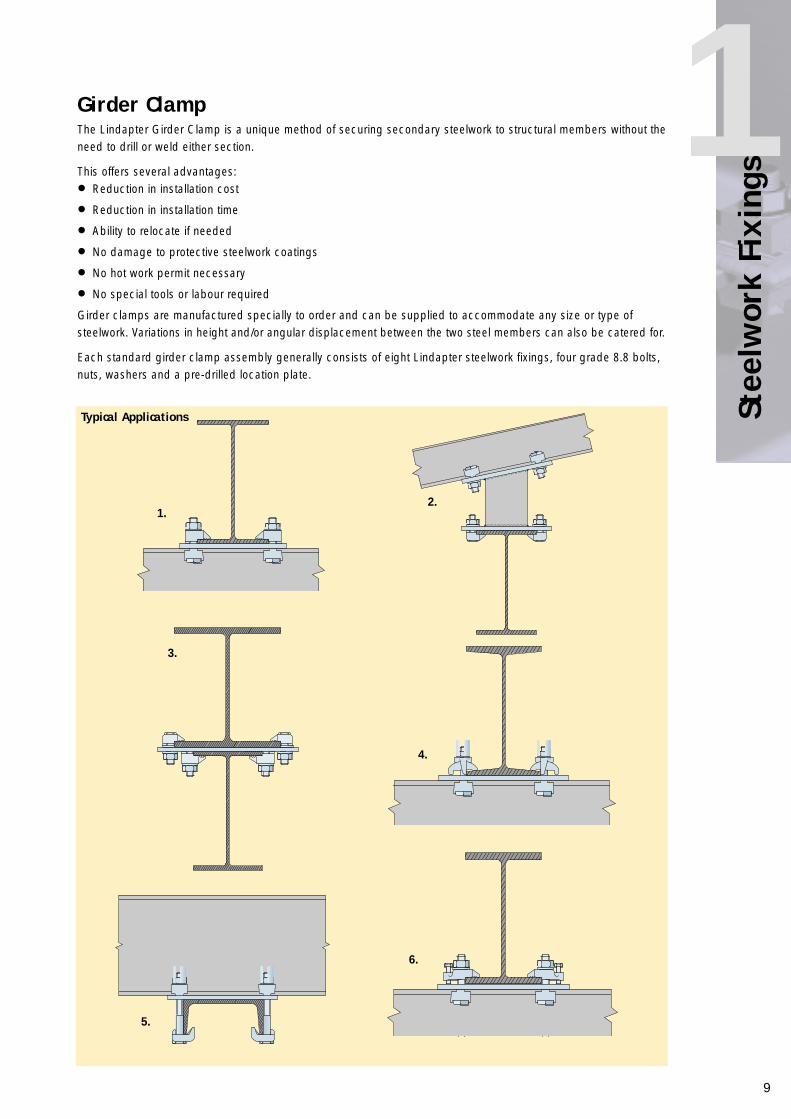
1The Lindapter Girder Clamp is a unique method of securing secondary steelwork to structural members without theneed to drill or weld either section.
This offers several advantages:
• Reduction in installation cost
• Reduction in installation time
• Ability to relocate if needed
• No damage to protective steelwork coatings
• No hot work permit necessary
• No special tools or labour required
Girder clamps are manufactured specially to order and can be supplied to accommodate any size or type ofsteelwork. Variations in height and/or angular displacement between the two steel members can also be catered for.
Each standard girder clamp assembly generally consists of eight Lindapter steelwork fixings, four grade 8.8 bolts,nuts, washers and a pre-drilled location plate.
Stee
lwor
k Fi
s1Girder Clamp
Typical Applications
1.
4.
5.
6.
2.
3.
10
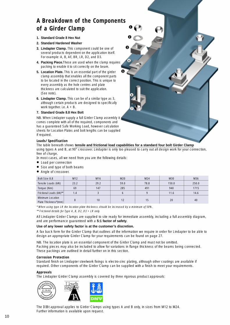
A Breakdown of the Componentsof a Girder Clamp1. Standard Grade 8 Hex Nut
2. Standard Hardened Washer
3. Lindapter Clamp. This component could be one of several products dependent on the application itself. For example: A, B, AF, BR, LR, D2, and D3.
4. Packing Piece.These are used when the clamp requires packing to enable it to sit correctly on the beam.
5. Location Plate. This is an essential part of the girder clamp assembly that enables all the component parts to be located in the correct position. This is unique to every assembly as the hole centres and plate thickness are calculated to suit the application. (See note).
6. Lindapter Clamp. This can be of a similar type as 3, although certain products are designed to specifically work together. i.e. A + B.
7. Standard Grade 8.8 Hex Bolt
NB. When Lindapter supply a full Girder Clamp assembly itcomes complete with all of the required, components andhas a guaranteed Safe Working Load, however calculationsheets for Location Plates and bolt lengths can be suppliedif required.
1
2
3
4
5
6
7
Loads/SpecificationThe table beneath shows tensile and frictional load capabilities for a standard four bolt Girder Clampusing types A and B, at 90° crossover. Lindapter is only too pleased to carry out all design work for your connection,free of charge. In most cases, all we need from you are the following details:
• Load per connection
• Size and type of both beams
• Angle of crossover.
Bolt Size 8.8 M12 M16 M20 M24 M30 M36
Tensile Loads (kN) 23.2 29.2 59.0 78.8 150.0 250.0
Torque (Nm) 69 147 285 491 940 1715
Frictional Loads (kN)** 1.4 3 6 9 11.6 14.6
Minimum Location8 10 12 15 20 40
Plate Thickness*(mm)
* When using type LR the location plate thickness should be increased by a minimum of 50%.** Frictional details for Type A, B, D2, D3 + LR only.
All Lindapter Girder Clamps are supplied to site ready for immediate assembly, including a full assembly diagram,and are performance guaranteed with a 5:1 factor of safety.
Use of any lower safety factor is at the customer’s discretion.
A fax back form for the Girder Clamp that outlines all the information we require in order for Lindapter to be able todesign an appropriate Girder Clamp for your requirements can be found on page 27.
NB. The location plate is an essential component of the Girder Clamp and must not be omitted.Packing pieces may also be included to allow for variations in flange thickness of the beams being connected.These packings are outlined in detail further on in this section.
Corrosion ProtectionStandard finish on Lindapter steelwork fixings is electro-zinc plating, although other coatings are available ifrequired. Other components of the Girder Clamp can be supplied with a finish to meet your requirements.
ApprovalsThe Lindapter Girder Clamp assembly is covered by three rigorous product approvals:
The DIBt approval applies to Girder Clamps using types A and B only, in sizes from M12 to M24.Further information is available upon request.
11
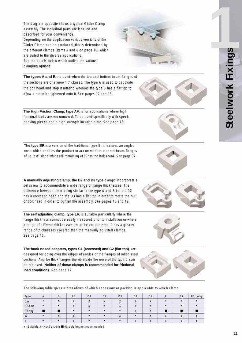
1The diagram opposite shows a typical Girder Clampassembly. The individual parts are labelled anddescribed for your convenience.Depending on the application various versions of theGirder Clamp can be produced, this is determined bythe different clamps (Items 3 and 6 on page 10) whichare suited to the diverse applications.See the details below which outline the variousclamping options:
Type A B LR D1 D2 D3 C1 C2 E BS BS Long
CW • • X X X X X X • • •P/Short • • X X X X X X • • •P/Long ■ ■ • • • • X X ■ ■ ■
W • X X • • X • X X X X
T • • X • • • X X X X X
•=Suitable X=Not Suitable ■ =Usable but not recommended
The following table gives a breakdown of which accessory or packing is applicable to which clamp.
The types A and B are used when the top and bottom beam flanges of
the sections are of a known thickness. The type A is used to captivate
the bolt head and stop it rotating whereas the type B has a flat top to
allow a nut to be tightened onto it. See pages 12 and 13.
The High Friction Clamp, type AF, is for applications where highfrictional loads are encountered. To be used specifically with specialpacking pieces and a high strength location plate. See page 15.
The type BR is a version of the traditional type B, it features an anglednose which enables the product to accommodate tapered beam flangesof up to 8° slope whilst still remaining at 90° to the bolt shank. See page 37.
A manually adjusting clamp, the D2 and D3 type clamps incorporate aset screw to accommodate a wide range of flange thicknesses. Thedifference between them being similar to the type A and B i.e. the D2has a recessed head and the D3 has a flat top in order to rotate the nutor bolt head in order to tighten the assembly. See pages 18 and 19.
The self adjusting clamp, type LR, is suitable particularly where theflange thickness cannot be easily measured prior to installation or wherea range of different thicknesses are to be encountered. It has a greaterrange of thicknesses covered than the manually adjusted clamps. See page 16.
The hook nosed adapters, types C1 (recessed) and C2 (flat top), aredesigned for going over the edges of angles or the flanges of rolled steelsections. And for thick flanges the rib inside the nose of the type C canbe removed. Neither of these clamps is recommended for frictionalload conditions. See page 17.
Stee
lwor
k Fi
s
12
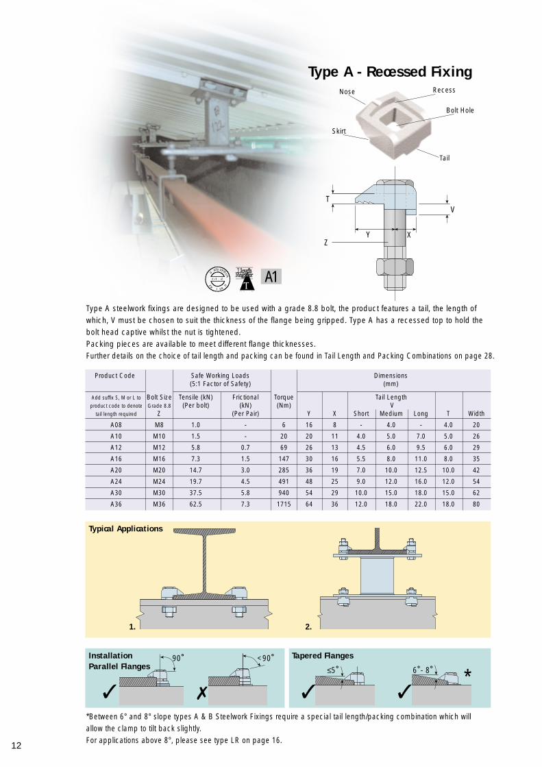
*Between 6° and 8° slope types A & B Steelwork Fixings require a special tail length/packing combination which willallow the clamp to tilt back slightly.For applications above 8°, please see type LR on page 16.
Type A - Recessed Fixing
Product Code Safe Working Loads Dimensions(5:1 Factor of Safety) (mm)
Add suffix S, M or L to Bolt Size Tensile (kN) Frictional Torque Tail Lengthproduct code to denote Grade 8.8 (Per bolt) (kN) (Nm) V
tail length required Z (Per Pair) Y X Short Medium Long T Width
A08 M8 1.0 - 6 16 8 - 4.0 - 4.0 20
A10 M10 1.5 - 20 20 11 4.0 5.0 7.0 5.0 26
A12 M12 5.8 0.7 69 26 13 4.5 6.0 9.5 6.0 29
A16 M16 7.3 1.5 147 30 16 5.5 8.0 11.0 8.0 35
A20 M20 14.7 3.0 285 36 19 7.0 10.0 12.5 10.0 42
A24 M24 19.7 4.5 491 48 25 9.0 12.0 16.0 12.0 54
A30 M30 37.5 5.8 940 54 29 10.0 15.0 18.0 15.0 62
A36 M36 62.5 7.3 1715 64 36 12.0 18.0 22.0 18.0 80
Typical Applications
InstallationParallel Flanges
Tapered Flanges
Type A steelwork fixings are designed to be used with a grade 8.8 bolt, the product features a tail, the length ofwhich, V must be chosen to suit the thickness of the flange being gripped. Type A has a recessed top to hold thebolt head captive whilst the nut is tightened.Packing pieces are available to meet different flange thicknesses.Further details on the choice of tail length and packing can be found in Tail Length and Packing Combinations on page 28.
90˚ <90˚≤5˚ 6˚- 8˚
✗✓ ✓ ✓
Recess
Bolt Hole
Tail
Nose
Skirt
V
XY
T
Z
*
A1
1. 2.
Stee
lwor
k Fi
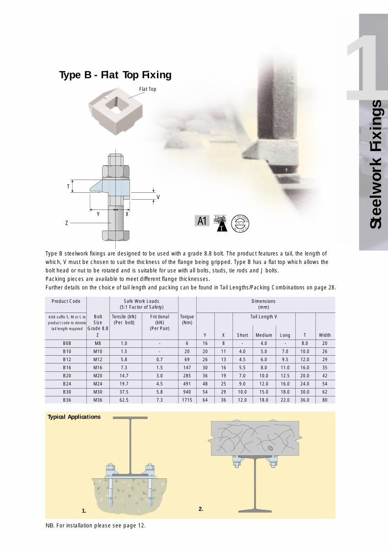
s1Type B - Flat Top Fixing
Product Code Safe Work Loads Dimensions(5:1 Factor of Safety) (mm)
Add suffix S, M or L to Bolt Tensile (kN) Frictional Torque Tail Length Vproduct code to denote Size (Per bolt) (kN) (Nm)
tail length required Grade 8.8 (Per Pair)Z Y X Short Medium Long T Width
B08 M8 1.0 - 6 16 8 - 4.0 - 8.0 20
B10 M10 1.5 - 20 20 11 4.0 5.0 7.0 10.0 26
B12 M12 5.8 0.7 69 26 13 4.5 6.0 9.5 12.0 29
B16 M16 7.3 1.5 147 30 16 5.5 8.0 11.0 16.0 35
B20 M20 14.7 3.0 285 36 19 7.0 10.0 12.5 20.0 42
B24 M24 19.7 4.5 491 48 25 9.0 12.0 16.0 24.0 54
B30 M30 37.5 5.8 940 54 29 10.0 15.0 18.0 30.0 62
B36 M36 62.5 7.3 1715 64 36 12.0 18.0 22.0 36.0 80
Typical Applications
Type B steelwork fixings are designed to be used with a grade 8.8 bolt. The product features a tail, the length ofwhich, V must be chosen to suit the thickness of the flange being gripped. Type B has a flat top which allows thebolt head or nut to be rotated and is suitable for use with all bolts, studs, tie rods and J bolts.Packing pieces are available to meet different flange thicknesses. Further details on the choice of tail length and packing can be found in Tail Lengths/Packing Combinations on page 28.
Flat Top
V
T
Z
Y XA1
1. 2.
NB. For installation please see page 12.
14
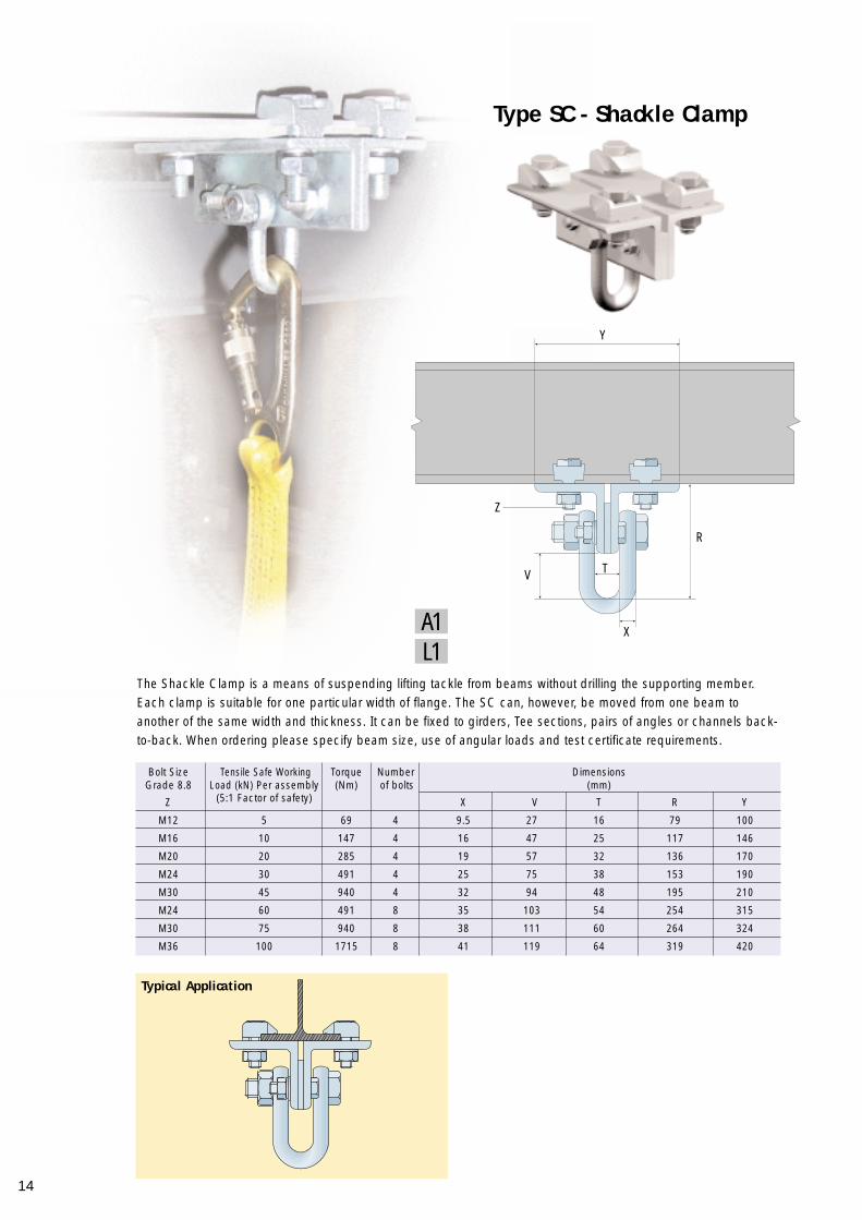
Type SC - Shackle Clamp
Typical Application
The Shackle Clamp is a means of suspending lifting tackle from beams without drilling the supporting member.Each clamp is suitable for one particular width of flange. The SC can, however, be moved from one beam toanother of the same width and thickness. It can be fixed to girders, Tee sections, pairs of angles or channels back-to-back. When ordering please specify beam size, use of angular loads and test certificate requirements.
Bolt Size Tensile Safe Working Torque Number Dimensions Grade 8.8 Load (kN) Per assembly (Nm) of bolts (mm)
Z (5:1 Factor of safety) X V T R Y
M12 5 69 4 9.5 27 16 79 100
M16 10 147 4 16 47 25 117 146
M20 20 285 4 19 57 32 136 170
M24 30 491 4 25 75 38 153 190
M30 45 940 4 32 94 48 195 210
M24 60 491 8 35 103 54 254 315
M30 75 940 8 38 111 60 264 324
M36 100 1715 8 41 119 64 319 420
V T
X
R
Z
Y
L1A1
15
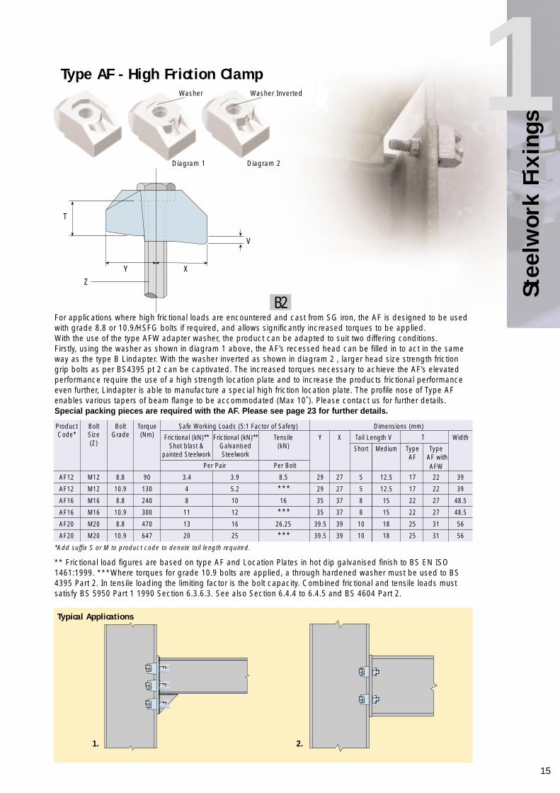
1For applications where high frictional loads are encountered and cast from SG iron, the AF is designed to be usedwith grade 8.8 or 10.9/HSFG bolts if required, and allows significantly increased torques to be applied.With the use of the type AFW adapter washer, the product can be adapted to suit two differing conditions.Firstly, using the washer as shown in diagram 1 above, the AF’s recessed head can be filled in to act in the sameway as the type B Lindapter. With the washer inverted as shown in diagram 2 , larger head size strength frictiongrip bolts as per BS4395 pt 2 can be captivated. The increased torques necessary to achieve the AF’s elevatedperformance require the use of a high strength location plate and to increase the products frictional performanceeven further, Lindapter is able to manufacture a special high friction location plate. The profile nose of Type AFenables various tapers of beam flange to be accommodated (Max 10˚). Please contact us for further details. Special packing pieces are required with the AF. Please see page 23 for further details.
* * Frictional load figures are based on type AF and Location Plates in hot dip galvanised finish to BS EN ISO1461:1999. * * * Where torques for grade 10.9 bolts are applied, a through hardened washer must be used to BS4395 Part 2. In tensile loading the limiting factor is the bolt capacity. Combined frictional and tensile loads mustsatisfy BS 5950 Part 1 1990 Section 6.3.6.3. See also Section 6.4.4 to 6.4.5 and BS 4604 Part 2.
Type AF - High Friction Clamp
Product Bolt Bolt Torque Safe Working Loads (5:1 Factor of Safety) Dimensions (mm)Code* Size Grade (Nm) Frictional (kN)** Frictional (kN)** Tensile Y X Tail Length V T Width
(Z) Shot blast & Galvanised (kN) Short Medium Type Typepainted Steelwork Steelwork AF AF with
Per Pair Per Bolt AFW
AF12 M12 8.8 90 3.4 3.9 8.5 29 27 5 12.5 17 22 39
AF12 M12 10.9 130 4 5.2 * * * 29 27 5 12.5 17 22 39
AF16 M16 8.8 240 8 10 16 35 37 8 15 22 27 48.5
AF16 M16 10.9 300 11 12 * * * 35 37 8 15 22 27 48.5
AF20 M20 8.8 470 13 16 26.25 39.5 39 10 18 25 31 56
AF20 M20 10.9 647 20 25 * * * 39.5 39 10 18 25 31 56
*Add suffix S or M to product code to denote tail length required.
Typical Applications
Washer InvertedWasher
Diagram 1 Diagram 2
V
XY
T
Z
1. 2.
B2
Stee
lwor
k Fi
s

16
An ingenious fixing which is able to adjust itself to meet the flange thickness of the steel beam being connected.Consisting of two parts, the LR is particularly suitable for applications where the flange thickness cannot be easilymeasured prior to installation, or where a range of different thicknesses will be encountered.The product’s saddle adjusts to provide a flat location point for the bolt head or nut. A further advantage of the LRis its suitability for use with sloping flanges on steelwork or rails up to 15°. For flange thicknesses beyond therange of adjustment, long packings can be used to make up the difference.NB. The nose of the LR must sit on the flange of the section being secured. Ensure that the straight and not thetapered leg of the saddle is in contact with the edge of the flange.
Type LR - Self Adjusting Clamp
Product Bolt Safe Working Load Torque Dimensions Code Size (5:1 Factor of Safety) (Nm) (mm)
Grade 8.8 Tensile (kN) Frictional(Per bolt) (kN)
Z (Per Pair) Y U X V Width
LR10 M10 1.5 - 20 46 15 6 3-10 33
LR12 M12 5.8 0.7 69 56 18.5 7 3-12 39
LR16 M16 7.3 1.5 147 67 22.5 8 3-16 46
LR20 M20 14.7 3.0 285 80 27 10 3-20 57
LR24 M24 19.7 4.5 491 106 35 12 3-24 76
NB. When using type LR the location plate thickness must be increased by 50%
Typical Applications
Saddle
TailClip
Nose
Bolt Hole
X
Y
U
V
Z
1. 2. 3.
A1
17
1
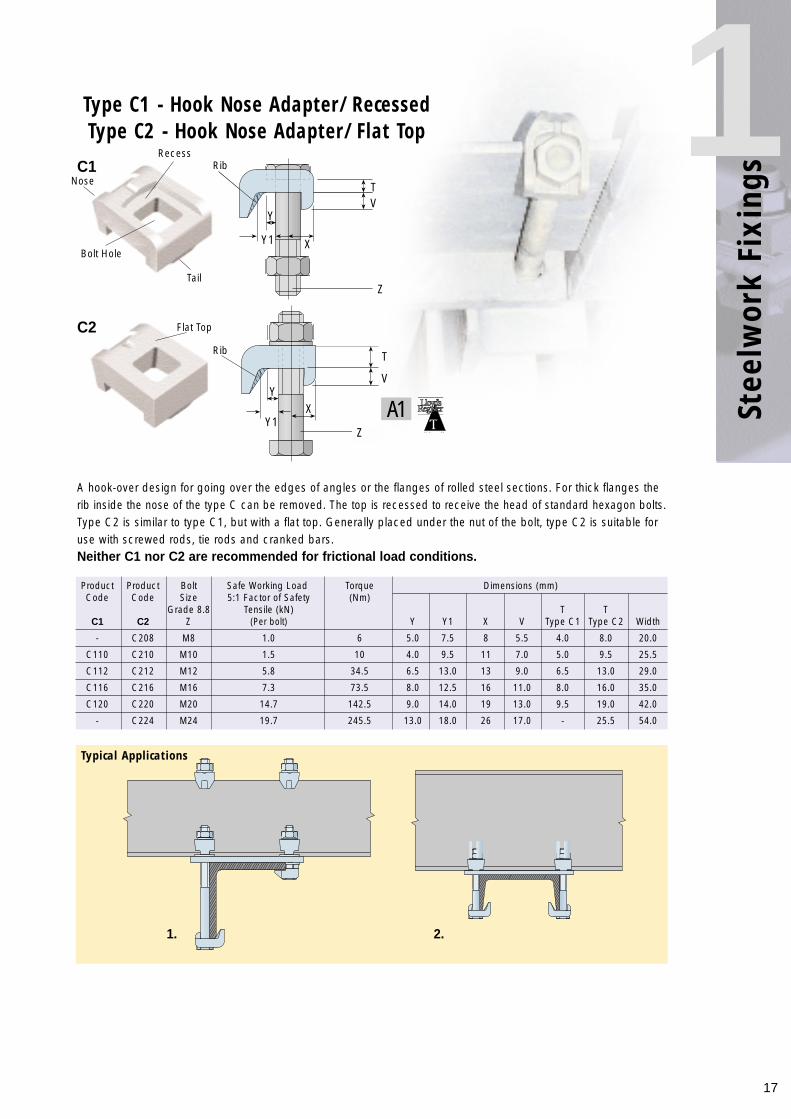
A hook-over design for going over the edges of angles or the flanges of rolled steel sections. For thick flanges therib inside the nose of the type C can be removed. The top is recessed to receive the head of standard hexagon bolts.Type C2 is similar to type C1, but with a flat top. Generally placed under the nut of the bolt, type C2 is suitable foruse with screwed rods, tie rods and cranked bars.Neither C1 nor C2 are recommended for frictional load conditions.
Typical Applications
Product Product Bolt Safe Working Load Torque Dimensions (mm)Code Code Size 5:1 Factor of Safety (Nm)
Grade 8.8 Tensile (kN) T TC1 C2 Z (Per bolt) Y Y1 X V Type C1 Type C2 Width
- C208 M8 1.0 6 5.0 7.5 8 5.5 4.0 8.0 20.0
C110 C210 M10 1.5 10 4.0 9.5 11 7.0 5.0 9.5 25.5
C112 C212 M12 5.8 34.5 6.5 13.0 13 9.0 6.5 13.0 29.0
C116 C216 M16 7.3 73.5 8.0 12.5 16 11.0 8.0 16.0 35.0
C120 C220 M20 14.7 142.5 9.0 14.0 19 13.0 9.5 19.0 42.0
- C224 M24 19.7 245.5 13.0 18.0 26 17.0 - 25.5 54.0
Type C1 - Hook Nose Adapter/RecessedType C2 - Hook Nose Adapter/Flat Top
Nose
RecessRib
Rib
Tail
Bolt Hole
Flat Top
TV
Z
Z
XY1
Y
T
V
XY1
Y
A1
C1
C2
2.1.
Stee
lwor
k Fi
s

18
The use of a setscrew tail allows the type D2 to accommodate a wide range of flange thicknesses without the useof packings (see figures V and V1 in table below) although packings can be used to increase its range. Otherwise,the clamp is used in the same way as the recessed fixing (A). Type D2 is suitable for both parallel and slopingflanges up to 5°.
Typical Application
Product Bolt Safe Working Load Torque Dimensions MinimumCode Size 5:1 Factor of Safety (Nm) (mm) Flange
Grade 8.8 Tensile (kN) Frictional thickness*Z (Per bolt) (Per Pair)(kN) Y X V V1 S T Width
D210 M10 1.5 - 20 20 20 20 10 M6 5 26 5
D212 M12 5.8 0.7 69 26 25 22 10 M6 6 29 5
D216 M16 7.3 1.5 147 30 30 20 13 M8 8 35 6.5
D220 M20 14.7 3.0 285 36 35 24 17 M10 10 42 8.5
D224 M24 19.7 4.5 491 48 49 30 19 M12 12 54 10
*On thin flanges it is necessary to invert the tail adjustment setscrew
NB. The following installation instructions apply to both D2 and D3
1. The tail screw on both products must be set to 1mm less than the length required before tightening the bolt, then rotated until the top edge of the Lindapter is at approx. 90˚ to the bolt shank.
2. Types D2 and D3 are suitable for flanges up to 5˚ taper only
Type D2 - Adjustable Tail Length Fixing/Recessed
A1
Recess
Bolt Hole
Skirt
Nose
Setscrew Tail
S
T
V
XY
ZV1
<90˚ 90˚≤5˚ >5˚
✗✓ ✓ ✗
Tapered FlangesInstallationParallel Flanges 90˚
1. 2.
90˚
19
Stee
lwor
k Fi
s1
*On thin flanges it is necessary to invert the tail adjustment setscrew
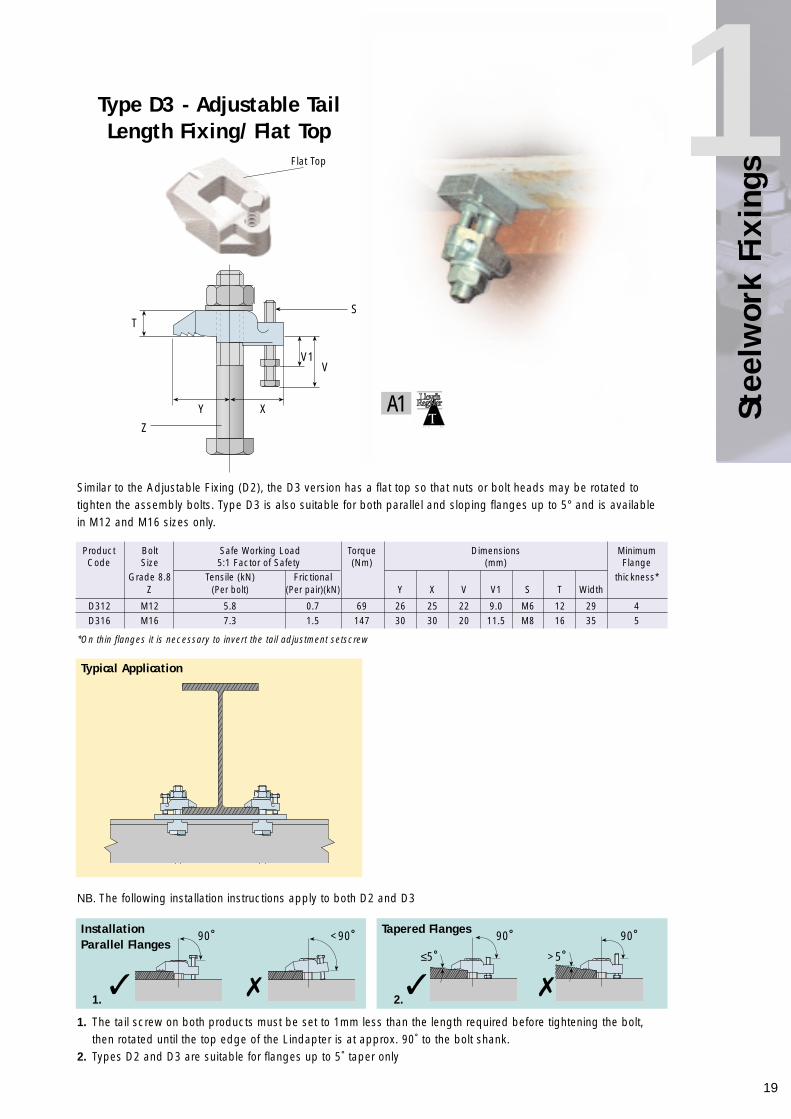
Similar to the Adjustable Fixing (D2), the D3 version has a flat top so that nuts or bolt heads may be rotated totighten the assembly bolts. Type D3 is also suitable for both parallel and sloping flanges up to 5° and is availablein M12 and M16 sizes only.
NB. The following installation instructions apply to both D2 and D3
Product Bolt Safe Working Load Torque Dimensions MinimumCode Size 5:1 Factor of Safety (Nm) (mm) Flange
Grade 8.8 Tensile (kN) Frictional thickness*Z (Per bolt) (Per pair)(kN) Y X V V1 S T Width
D312 M12 5.8 0.7 69 26 25 22 9.0 M6 12 29 4D316 M16 7.3 1.5 147 30 30 20 11.5 M8 16 35 5
Typical Application
A1
Flat Top
V
XY
Z
TS
V1
Type D3 - Adjustable TailLength Fixing/Flat Top
1. The tail screw on both products must be set to 1mm less than the length required before tightening the bolt, then rotated until the top edge of the Lindapter is at approx. 90˚ to the bolt shank.
2. Types D2 and D3 are suitable for flanges up to 5˚ taper only
<90˚ 90˚≤5˚ >5˚
✗✓ ✓ ✗
Tapered FlangesInstallationParallel Flanges
90˚
1. 2.
90˚
20
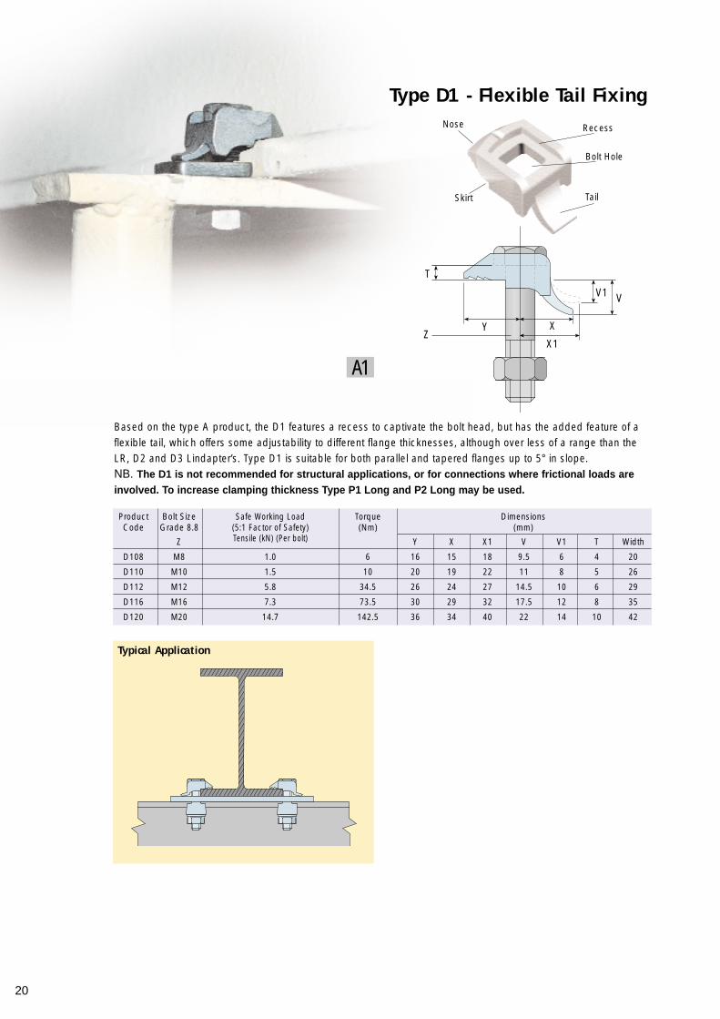
Type D1 - Flexible Tail Fixing
Typical Application
Product Bolt Size Safe Working Load Torque Dimensions Code Grade 8.8 (5:1 Factor of Safety) (Nm) (mm)
Z Tensile (kN) (Per bolt) Y X X1 V V1 T Width
D108 M8 1.0 6 16 15 18 9.5 6 4 20
D110 M10 1.5 10 20 19 22 11 8 5 26
D112 M12 5.8 34.5 26 24 27 14.5 10 6 29
D116 M16 7.3 73.5 30 29 32 17.5 12 8 35
D120 M20 14.7 142.5 36 34 40 22 14 10 42
Based on the type A product, the D1 features a recess to captivate the bolt head, but has the added feature of aflexible tail, which offers some adjustability to different flange thicknesses, although over less of a range than theLR, D2 and D3 Lindapter’s. Type D1 is suitable for both parallel and tapered flanges up to 5° in slope.NB. The D1 is not recommended for structural applications, or for connections where frictional loads areinvolved. To increase clamping thickness Type P1 Long and P2 Long may be used.
Recess
Tail
Nose
Skirt
Bolt Hole
VV1
X1Z
Y
T
X
A1
21
Stee
lwor
k Fi
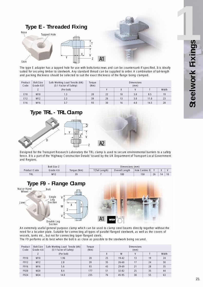
s1Type E - Threaded Fixing
The type E adapter has a tapped hole for use with bolts/setscrews and can be countersunk if specified. It is ideallysuited for securing timber to steelwork. Any standard thread can be supplied to order. A combination of tail-lengthand packing thickness should be selected to suit the exact thickness of the flange being clamped.
Product Bolt Size Safe Working Load Tensile (kN) Torque Dimensions Code Grade 8.8 (5:1 Factor of Safety) (Nm) (mm)
Z (Per bolt) Y X V T Width
E10 M10 1.3 20 22 10 3.0 8.5 19
E12 M12 2.3 39 26 13 3.0 11.0 23
E16 M16 3.7 93 30 16 4.0 14.5 28
Type TRL - TRL Clamp
Bolt Size Z Dimensions (mm)Product Code Grade 4.6 Torque (Nm) T(Tail Length) Overall Length Hole Centres D Y X V
TRL M12 39 7 180 150 26 14 10
Designed for the Transport Research Laboratory the TRL clamp is used to secure environmental barriers to a safetyfence. It is a part of the ‘Highway Construction Details’ issued by the UK Department of Transport Local Governmentand Regions.
Type F9 - Flange Clamp
An extremely useful general purpose clamp which can be used to clamp steel beams directly together without theneed for a location plate. Suitable for connecting all types of parallel flanged steelwork, as well as the covers ofvessels, tanks etc., but not for connecting taper flanged steels.The F9 performs at its best when the bolt is as close as possible to the steelwork being secured.
Product Bolt Size Safe Working Load Tensile (kN) Torque Dimensions Code Grade 4.6 (5:1 Factor of Safety) (Nm) (mm)
Z (Per bolt) X W V T Width
F910 M10 1.96 20 25 19-42 13 19 24
F912 M12 2.8 39 35 26-60 17 24 30
F916 M16 5.6 93 43 29-69 21 28 35
F920 M20 8.4 177 51 32-82 25 35 44
F924 M24 14.0 235 76 45-95 38 55 63
Tapped Hole
Skirt
Jaws
Nut or HandWheel
Double LegSection
Bolt
SingleLeg
Section
Nose
V
T
Y
T
Z
VXY
W
V
V
Z
X T
X
Z A1
A2
A1
D
22
Product Bolt Size Safe Working Load Torque DimensionsCode Grade 8.8 (5:1 Factor of Safety) Tensile (kN) (Nm) (mm)
Z (Per bolt) Y X T Width
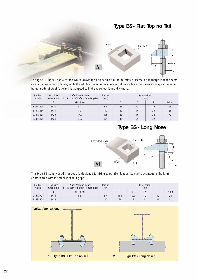
B12P4109 M12 5.8 69 26 13 16 29
B16P3560 M16 7.3 147 30 16 20 35
B20P3208 M20 14.7 285 36 19 24 42
B24P3870 M24 19.7 491 48 25 32 54
Typical Applications
Type BS - Flat Top no Tail
The Type BS no tail has a flat top which allows the bolt head or nut to be rotated. Its main advantage is that beamscan lie flange against flange, while the whole connection is made up of only a few components using a connectingframe made of steel flat which is adapted to fit the required flange thickness.
The Type BS Long Nosed is especially designed for fixing to parallel flanges. Its main advantage is the largecontact area with the steel section it grips
Product Bolt Size Safe Working Load Torque DimensionsCode Grade 8.8 (5:1 Factor of Safety) Tensile (kN) (Nm) (mm)
Z (Per bolt) Y X V T Width
B12P3777 M12 5.8 69 45.5 15.5 6 17 28B16P2929 M16 7.3 147 44 17 11 16 32
Nose
Extended Nose
Skirt Tail
Flat Top
Bolt Hole
T
YX
Y XV
Z
Z
T
A1
A1
1. 2.
Type BS - Long Nose
Type BS - Flat Top no Tail Type BS - Long Nosed
23
Stee
lwor
k Fi
s1
Product Bolt Dimensions Code Size (mm)
Short Long TP1 P2 P1 P2 Z Y XS XL P1 P2 Width
P1S08 P2S08 P1L08 P2L08 M8 4 10 20 4 8 21
P1S10 P2S10 P1L10 P2L10 M10 5 13 24 5 10 24
P1S12 P2S12 P1L12 P2L12 M12 6 16 32 6 12 30
P1S16 P2S16 P1L16 P2L16 M16 8 21 40 8 16 35
P1S20 P2S20 P1L20 P2L20 M20 10 23 47 10 20 43
P1S24 P2S24 P1L24 P2L24 M24 12 32 64 12 24 54
P1S30 P2S30 - - M30 15 35 - 15 30 62
P1S36 P2S36 - - M36 18 42 - 18 36 80
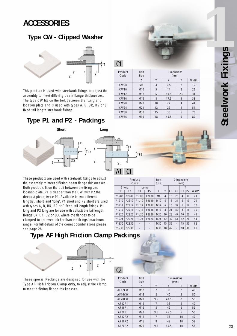
Type AF High Friction Clamp Packings
These special Packings are designed for use with theType AF High Friction Clamp only, to adjust the clampto meet differing flange thicknesses.
Product Bolt Dimensions Code Size (mm)
Z Y X T WidthAF12CW M12 7 33 2 40
AF16CW M16 8 40 2 50
AF20CW M20 9.5 40.5 2 55
AF12P1 M12 7 33 5 40AF16P1 M16 8 42 5 52
AF20P1 M20 9.5 45.5 5 56
AF12P2 M12 7 33 10 40
AF16P2 M16 8 42 10 52
AF20P2 M20 9.5 45.5 10 56
ACCESSORIES
Type CW - Clipped Washer
This product is used with steelwork fixings to adjust theassembly to meet differing beam flange thicknesses.The type CW fits on the bolt between the fixing andlocation plate and is used with types A, B, BR, BS or Efixed tail length steelwork fixings.
Product Bolt DimensionsCode Size (mm)
Z Y X T Width
CW08 M8 4 9.5 2 19
CW10 M10 5 14 2 25
CW12 M12 6 19.5 2.5 31
CW16 M16 8 17.5 3 38
CW20 M20 10 22 4 44
CW24 M24 12 29 4 57
CW30 M30 15 36 5 70
CW36 M36 18 45.5 5 89
These products are used with steelwork fixings to adjustthe assembly to meet differing beam flange thicknesses.Both products fit on the bolt between the fixing andlocation plate. P1 is deeper than the CW, with P2 thedeepest piece, twice P1. Available in two differentlengths, ‘short’ and ‘long’. P1 short and P2 short are usedwith types A, B, BR, BS or E fixed tail length fixings. P1long and P2 long are for use with adjustable tail lengthfixings LR, D1, D2 or D3, where the flanges to beclamped to are even thicker than the fixings’ maximumrange. For full details of the correct combinations pleasesee page 28.
Type P1 and P2 - Packings
TP2
TP1
TP2
TP1
Z
Y X
T
Z
Y XS Y
Z
T
XYZ
XL
C1
C2
A1 C1
Short Long
24
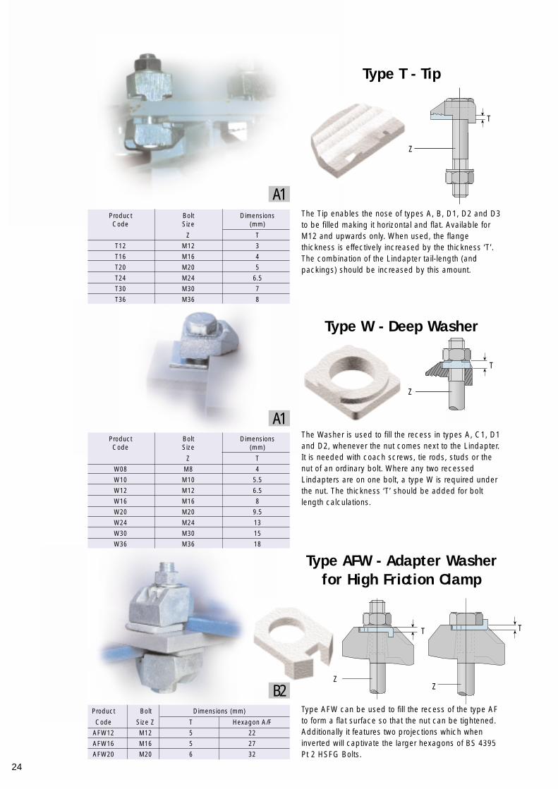
Type T - Tip
Type AFW - Adapter Washerfor High Friction Clamp
The Tip enables the nose of types A, B, D1, D2 and D3to be filled making it horizontal and flat. Available forM12 and upwards only. When used, the flangethickness is effectively increased by the thickness ‘T’.The combination of the Lindapter tail-length (andpackings) should be increased by this amount.
The Washer is used to fill the recess in types A, C1, D1and D2, whenever the nut comes next to the Lindapter.It is needed with coach screws, tie rods, studs or thenut of an ordinary bolt. Where any two recessedLindapters are on one bolt, a type W is required underthe nut. The thickness ‘T’ should be added for boltlength calculations.
Type AFW can be used to fill the recess of the type AFto form a flat surface so that the nut can be tightened.Additionally it features two projections which wheninverted will captivate the larger hexagons of BS 4395Pt 2 HSFG Bolts.
Product Bolt DimensionsCode Size (mm)
Z T
T12 M12 3
T16 M16 4
T20 M20 5
T24 M24 6.5
T30 M30 7
T36 M36 8
Product Bolt DimensionsCode Size (mm)
Z T
W08 M8 4
W10 M10 5.5
W12 M12 6.5
W16 M16 8
W20 M20 9.5
W24 M24 13
W30 M30 15
W36 M36 18
Product Bolt Dimensions (mm)
Code Size Z T Hexagon A/F
AFW12 M12 5 22
AFW16 M16 5 27
AFW20 M20 6 32
A1
A1
B2
T
Z
T
Z
ZZ
T T
Type W - Deep Washer
25
Stee
lwor
k Fi
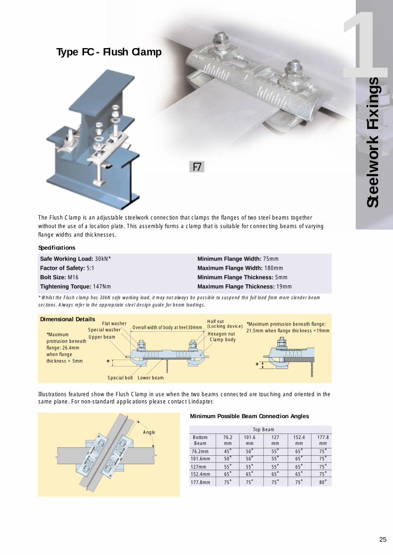
s1Type FC - Flush Clamp
* Whilst the Flush clamp has 30kN safe working load, it may not always be possible to suspend this full load from more slender beamsections. Always refer to the appropriate steel design guide for beam loadings.
Illustrations featured show the Flush Clamp in use when the two beams connected are touching and oriented in thesame plane. For non-standard applications please contact Lindapter.
Specifications
Safe Working Load: 30kN* Minimum Flange Width: 75mm
Factor of Safety: 5:1 Maximum Flange Width: 180mm
Bolt Size: M16 Minimum Flange Thickness: 5mm
Tightening Torque: 147Nm Maximum Flange Thickness: 19mm
Dimensional Details
Top Beam
Bottom 76.2 101.6 127 152.4 177.8Beam mm mm mm mm mm
76.2mm 45˚ 50˚ 55˚ 65˚ 75˚101.6mm 50˚ 50˚ 55˚ 65˚ 75˚127mm 55˚ 55˚ 55˚ 65˚ 75˚152.4mm 65˚ 65˚ 65˚ 65˚ 75˚177.8mm 75˚ 75˚ 75˚ 75˚ 80˚
Minimum Possible Beam Connection Angles
The Flush Clamp is an adjustable steelwork connection that clamps the flanges of two steel beams togetherwithout the use of a location plate. This assembly forms a clamp that is suitable for connecting beams of varyingflange widths and thicknesses.
*Maximumprotrusion beneathflange: 26.4mmwhen flangethickness = 5mm
*Maximum protrusion beneath flange:21.5mm when flange thickness =19mm
Flat washerOverall width of body at heel:304mmSpecial washer
Upper beam
* *Special bolt Lower beam
Angle
Half nut(Locking device)
Hexagon nutClamp body
F7

26
Loads and SpecificationsReference is made throughout this catalogue to loads related to our product applications. Given loads are for boltgrade 8.8 unless otherwise stated. These are defined below (all Lindapter quoted loads have been obtained fromfull scale physical tests)Should you have any difficulty in selecting the correct product for your needs, please contact us.
Tensile LoadingIn tensile applications the load transmits a force parallel to the centre line ofthe bolt shank, hence applying a load to the contact point of the Lindapter.See product data tables for allowable tensile loads at varying bolt sizes.
Shear LoadingHere, the Safe Working Load of the assembly is determined by the boltgrade and diameter as the force is resisted by the cross sectional area ofthe bolt shanks. It is recommended that reference be made to the boltmanufacturers’ technical literature or the relevant structural steel designcode to ascertain a Safe Working Load per bolt.
Frictional LoadingThe force is applied at 90° to the bolt shank. The point at which slip occursdepends upon the condition and finish of the steelwork, the coating of theLindapter and the grade of bolt used. Slip is defined as the constant load atwhich relative movement between clamped components exceeds 0.1mm.
Published frictional loads are based on electro-zinc plated products clamping onto painted steelwork, whichgives the lowest coefficient of friction.These loads are also based on a two-bolt connection, the lowest allowable for a frictional assembly. This should bemultiplied for the number of bolts used as appropriate.For further details on any frictional application, please contact Lindapter - we are only too pleased to help.For specific high friction applications please see page 15.
Combined LoadsWhen the fixings are subject to more than one load condition, the resultingforces must be calculated to determine the product and bolt sizes required.Please contact Lindapter with your application.
Compression LoadingForce here is applied direct to the supporting section rather than theLindapter products. If, however, there is a gap between the surfaces beingconnected, the buckling strength of the supporting fabrication must beconsidered.
TorqueThe recommended torque values stated in the product sections must beapplied in order to achieve the stated Safe Working Loads. Any reduction intorques applied will lower the product Safe Working Load.
27
Stee
lwor
k Fi
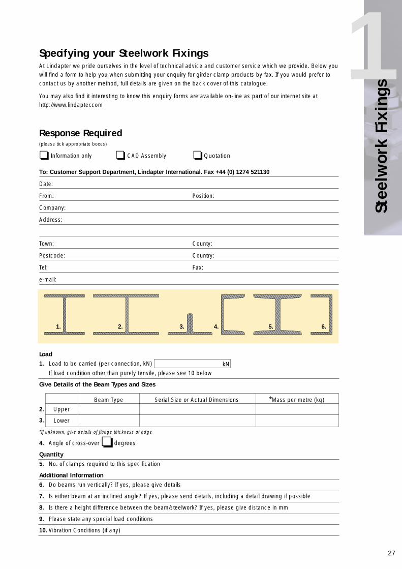
s1Specifying your Steelwork FixingsAt Lindapter we pride ourselves in the level of technical advice and customer service which we provide. Below youwill find a form to help you when submitting your enquiry for girder clamp products by fax. If you would prefer tocontact us by another method, full details are given on the back cover of this catalogue.
You may also find it interesting to know this enquiry forms are available on-line as part of our internet site athttp://www.lindapter.com
Response Required(please tick appropriate boxes)
❏ Information only ❏ CAD Assembly ❏ Quotation
To: Customer Support Department, Lindapter International. Fax +44 (0) 1274 521130
Date:
From: Position:
Company:
Address:
Town: County:
Postcode: Country:
Tel: Fax:
e-mail:
Load1. Load to be carried (per connection, kN)
If load condition other than purely tensile, please see 10 below
Give Details of the Beam Types and Sizes
2.
3.
*If unknown, give details of flange thickness at edge
4. Angle of cross-over ❏ degrees
Quantity5. No. of clamps required to this specification
Additional Information6. Do beams run vertically? If yes, please give details
7. Is either beam at an inclined angle? If yes, please send details, including a detail drawing if possible
8. Is there a height difference between the beam/steelwork? If yes, please give distance in mm
9. Please state any special load conditions
10. Vibration Conditions (if any)
kN
Beam Type Serial Size or Actual Dimensions *Mass per metre (kg)
Upper
Lower
1. 2. 3. 4. 5. 6.
28
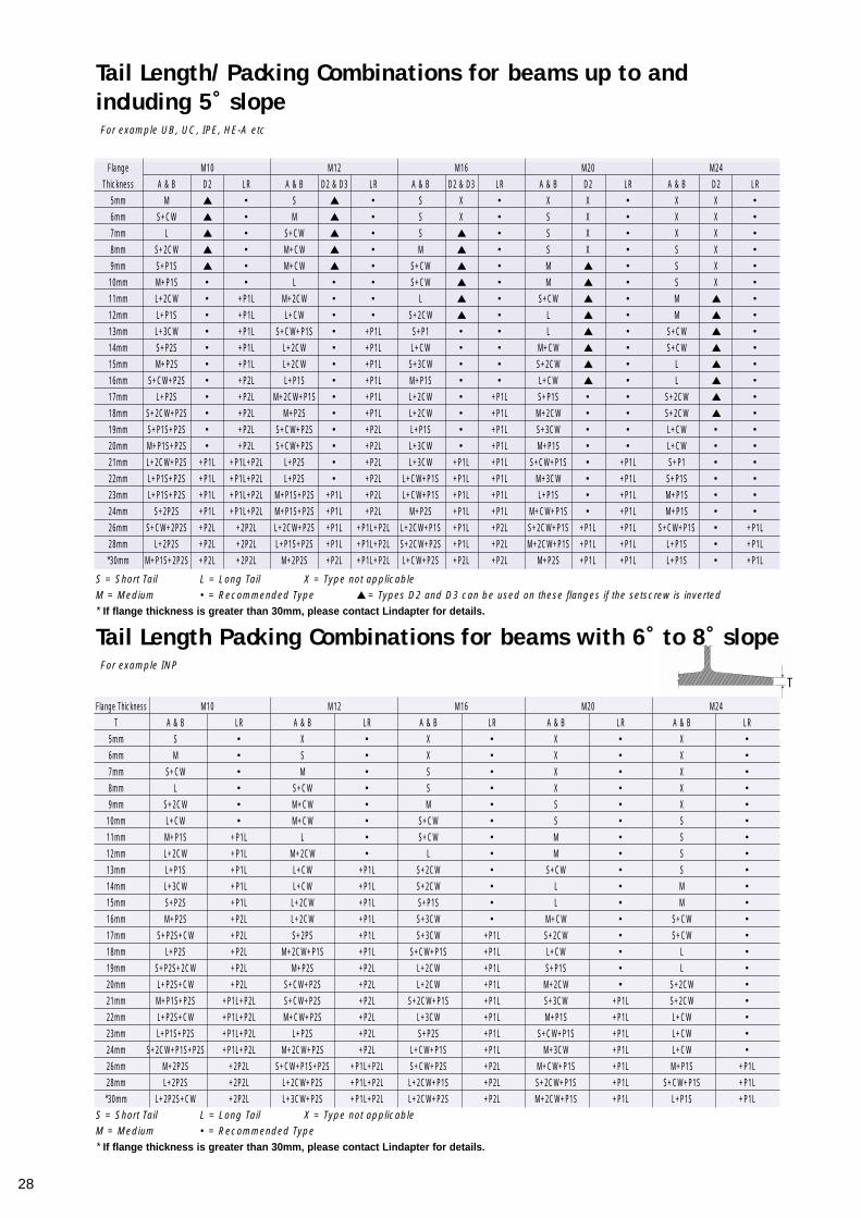
Tail Length/Packing Combinations for beams up to andincluding 5˚ slopeFor example UB, UC, IPE, HE-A etc
Tail Length Packing Combinations for beams with 6˚ to 8˚ slopeFor example INP
Flange M10 M12 M16 M20 M24
Thickness A & B D2 LR A & B D2 & D3 LR A & B D2 & D3 LR A & B D2 LR A & B D2 LR
5mm M ▲ • S ▲ • S X • X X • X X •
6mm S+CW ▲ • M ▲ • S X • S X • X X •
7mm L ▲ • S+CW ▲ • S ▲ • S X • X X •
8mm S+2CW ▲ • M+CW ▲ • M ▲ • S X • S X •
9mm S+P1S ▲ • M+CW ▲ • S+CW ▲ • M ▲ • S X •
10mm M+P1S • • L • • S+CW ▲ • M ▲ • S X •
11mm L+2CW • +P1L M+2CW • • L ▲ • S+CW ▲ • M ▲ •
12mm L+P1S • +P1L L+CW • • S+2CW ▲ • L ▲ • M ▲ •
13mm L+3CW • +P1L S+CW+P1S • +P1L S+P1 • • L ▲ • S+CW ▲ •
14mm S+P2S • +P1L L+2CW • +P1L L+CW • • M+CW ▲ • S+CW ▲ •
15mm M+P2S • +P1L L+2CW • +P1L S+3CW • • S+2CW ▲ • L ▲ •
16mm S+CW+P2S • +P2L L+P1S • +P1L M+P1S • • L+CW ▲ • L ▲ •
17mm L+P2S • +P2L M+2CW+P1S • +P1L L+2CW • +P1L S+P1S • • S+2CW ▲ •
18mm S+2CW+P2S • +P2L M+P2S • +P1L L+2CW • +P1L M+2CW • • S+2CW ▲ •
19mm S+P1S+P2S • +P2L S+CW+P2S • +P2L L+P1S • +P1L S+3CW • • L+CW • •
20mm M+P1S+P2S • +P2L S+CW+P2S • +P2L L+3CW • +P1L M+P1S • • L+CW • •
21mm L+2CW+P2S +P1L +P1L+P2L L+P2S • +P2L L+3CW +P1L +P1L S+CW+P1S • +P1L S+P1 • •
22mm L+P1S+P2S +P1L +P1L+P2L L+P2S • +P2L L+CW+P1S +P1L +P1L M+3CW • +P1L S+P1S • •
23mm L+P1S+P2S +P1L +P1L+P2L M+P1S+P2S +P1L +P2L L+CW+P1S +P1L +P1L L+P1S • +P1L M+P1S • •
24mm S+2P2S +P1L +P1L+P2L M+P1S+P2S +P1L +P2L M+P2S +P1L +P1L M+CW+P1S • +P1L M+P1S • •
26mm S+CW+2P2S +P2L +2P2L L+2CW+P2S +P1L +P1L+P2L L+2CW+P1S +P1L +P2L S+2CW+P1S +P1L +P1L S+CW+P1S • +P1L
28mm L+2P2S +P2L +2P2L L+P1S+P2S +P1L +P1L+P2L S+2CW+P2S +P1L +P2L M+2CW+P1S +P1L +P1L L+P1S • +P1L
*30mm M+P1S+2P2S +P2L +2P2L M+2P2S +P2L +P1L+P2L L+CW+P2S +P2L +P2L M+P2S +P1L +P1L L+P1S • +P1L
Flange Thickness M10 M12 M16 M20 M24
T A & B LR A & B LR A & B LR A & B LR A & B LR
5mm S • X • X • X • X •
6mm M • S • X • X • X •
7mm S+CW • M • S • X • X •
8mm L • S+CW • S • X • X •
9mm S+2CW • M+CW • M • S • X •
10mm L+CW • M+CW • S+CW • S • S •
11mm M+P1S +P1L L • S+CW • M • S •
12mm L+2CW +P1L M+2CW • L • M • S •
13mm L+P1S +P1L L+CW +P1L S+2CW • S+CW • S •
14mm L+3CW +P1L L+CW +P1L S+2CW • L • M •
15mm S+P2S +P1L L+2CW +P1L S+P1S • L • M •
16mm M+P2S +P2L L+2CW +P1L S+3CW • M+CW • S+CW •
17mm S+P2S+CW +P2L S+2PS +P1L S+3CW +P1L S+2CW • S+CW •
18mm L+P2S +P2L M+2CW+P1S +P1L S+CW+P1S +P1L L+CW • L •
19mm S+P2S+2CW +P2L M+P2S +P2L L+2CW +P1L S+P1S • L •
20mm L+P2S+CW +P2L S+CW+P2S +P2L L+2CW +P1L M+2CW • S+2CW •
21mm M+P1S+P2S +P1L+P2L S+CW+P2S +P2L S+2CW+P1S +P1L S+3CW +P1L S+2CW •
22mm L+P2S+CW +P1L+P2L M+CW+P2S +P2L L+3CW +P1L M+P1S +P1L L+CW •
23mm L+P1S+P2S +P1L+P2L L+P2S +P2L S+P2S +P1L S+CW+P1S +P1L L+CW •
24mm S+2CW+P1S+P2S +P1L+P2L M+2CW+P2S +P2L L+CW+P1S +P1L M+3CW +P1L L+CW •
26mm M+2P2S +2P2L S+CW+P1S+P2S +P1L+P2L S+CW+P2S +P2L M+CW+P1S +P1L M+P1S +P1L
28mm L+2P2S +2P2L L+2CW+P2S +P1L+P2L L+2CW+P1S +P2L S+2CW+P1S +P1L S+CW+P1S +P1L
*30mm L+2P2S+CW +2P2L L+3CW+P2S +P1L+P2L L+2CW+P2S +P2L M+2CW+P1S +P1L L+P1S +P1L
S = Short Tail L = Long Tail X = Type not applicableM = Medium • = Recommended Type ▲= Types D2 and D3 can be used on these flanges if the setscrew is inverted* If flange thickness is greater than 30mm, please contact Lindapter for details.
S = Short Tail L = Long Tail X = Type not applicableM = Medium • = Recommended Type* If flange thickness is greater than 30mm, please contact Lindapter for details.
T
29
Stee
lwor
k Fi
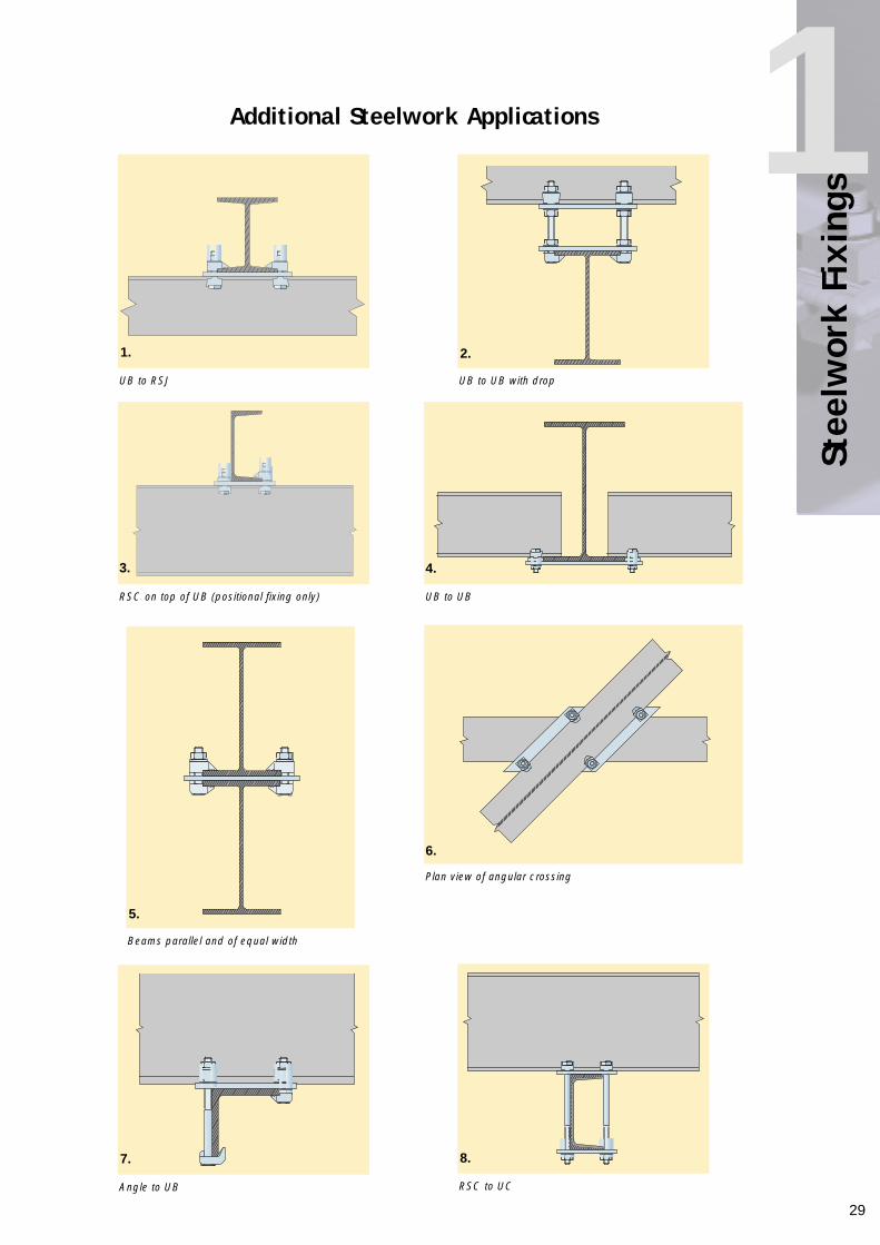
s1Additional Steelwork Applications
UB to RSJ
RSC on top of UB (positional fixing only) UB to UB
Plan view of angular crossing
RSC to UCAngle to UB
Beams parallel and of equal width
UB to UB with drop
1. 2.
3. 4.
5.
7. 8.
6.
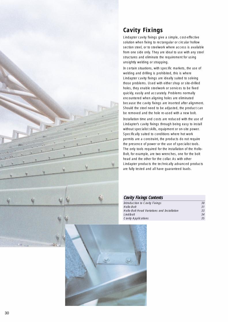
Lindapter cavity fixings give a simple, cost-effectivesolution when fixing to rectangular or circular hollowsection steel, or to steelwork where access is availablefrom one side only. They are ideal to use with any steelstructures and eliminate the requirement for usingunsightly welding or strapping.
In certain situations, with specific markets, the use ofwelding and drilling is prohibited, this is whereLindapter cavity fixings are ideally suited to solvingthose problems. Used with either shop or site-drilledholes, they enable steelwork or services to be fixedquickly, easily and accurately. Problems normallyencountered when aligning holes are eliminatedbecause the cavity fixings are inserted after alignment.Should the steel need to be adjusted, the product canbe removed and the hole re-used with a new bolt.
Installation time and costs are reduced with the use ofLindapter’s cavity fixings through being easy to installwithout specialist skills, equipment or on-site power.Specifically suited to conditions where hot workpermits are a constraint, the products do not requirethe presence of power or the use of specialist tools.The only tools required for the installation of the Hollo-Bolt, for example, are two wrenches, one for the bolthead and the other for the collar. As with otherLindapter products the technically advanced productsare fully tested and all have guaranteed loads.
Cavity Fixings
30
Cavity Fixings ContentsIntroduction to Cavity Fixings 30Hollo-Bolt 31Hollo-Bolt Head Variations and Installation 33Lindibolt 34Cavity Applications 35
31
Cavi
ty F
ixin
gs
2
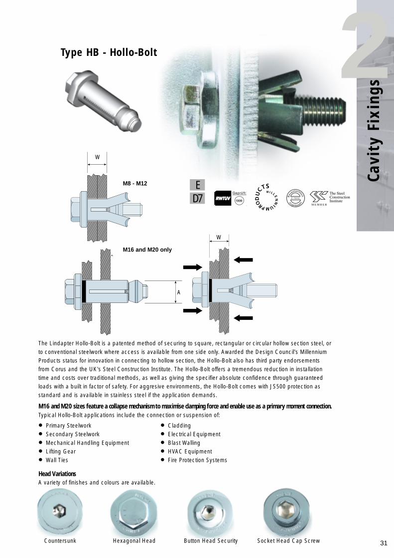
The Lindapter Hollo-Bolt is a patented method of securing to square, rectangular or circular hollow section steel, orto conventional steelwork where access is available from one side only. Awarded the Design Council's MillenniumProducts status for innovation in connecting to hollow section, the Hollo-Bolt also has third party endorsementsfrom Corus and the UK's Steel Construction Institute. The Hollo-Bolt offers a tremendous reduction in installationtime and costs over traditional methods, as well as giving the specifier absolute confidence through guaranteedloads with a built in factor of safety. For aggresive environments, the Hollo-Bolt comes with JS500 protection asstandard and is available in stainless steel if the application demands.
M16 and M20 sizes feature a collapse mechanism to maximise clamping force and enable use as a primary moment connection. Typical Hollo-Bolt applications include the connection or suspension of:
• Primary Steelwork • Cladding
• Secondary Steelwork • Electrical Equipment
• Mechanical Handling Equipment • Blast Walling
• Lifting Gear • HVAC Equipment
• Wall Ties • Fire Protection Systems
Type HB - Hollo-Bolt
W
W
A
M8 - M12
M16 and M20 only
ED7
Button Head SecurityCountersunk Socket Head Cap ScrewHexagonal Head
Head VariationsA variety of finishes and colours are available.
The guide provides design guidence for the use of Hollo-Bolt and gives essential information forstructural steelwork connections for use in buildings designed by the "Simple Method" i.e. braced frames where connections carry mainly shear and axial loads only.
To obtain further details on the Simple Connections guide please contact The Steel Construction Institute on Tel: +44 (0) 1344 623 345 or Fax: +44 (0) 1344 622 944
Published by SCI/BCSA Connections Group.Publication Number: P212 ISBN 1 85942 072 932
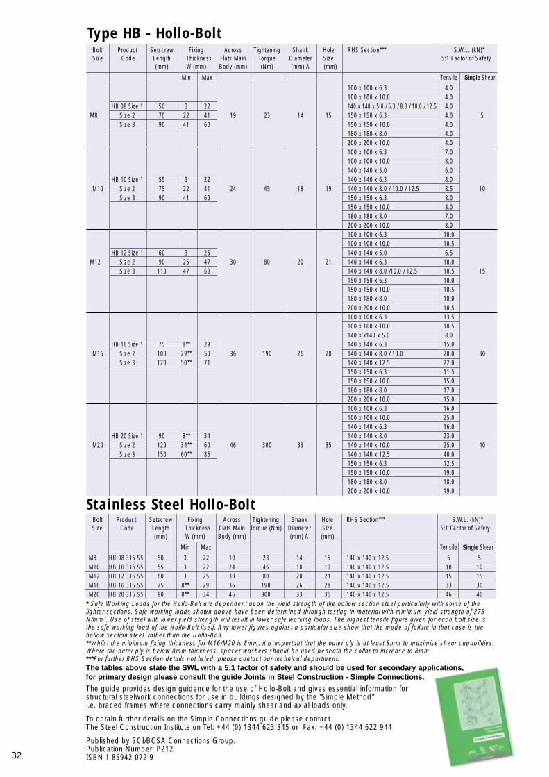
* Safe Working Loads for the Hollo-Bolt are dependent upon the yield strength of the hollow section steel particularly with some of thelighter sections. Safe working loads shown above have been determined through testing in material with minimum yield strength of 275N/mm 2. Use of steel with lower yield strength will result in lower safe working loads. The highest tensile figure given for each bolt size isthe safe working load of the Hollo-Bolt itself. Any lower figures against a particular size show that the mode of failure in that case is thehollow section steel, rather than the Hollo-Bolt.**Whilst the minimum fixing thickness for M16/M20 is 8mm, it is important that the outer ply is at least 8mm to maximise shear capabilities.Where the outer ply is below 8mm thickness, spacer washers should be used beneath the collar to increase to 8mm.***For further RHS Section details not listed, please contact our technical department.
Type HB - Hollo-Bolt
Stainless Steel Hollo-BoltBolt Product Setscrew Fixing Across Tightening Shank Hole RHS Section*** S.W.L. (kN)*Size Code Length Thickness Flats Main Torque (Nm) Diameter Size 5:1 Factor of Safety
(mm) W (mm) Body (mm) (mm) A (mm)
Min Max Tensile Single Shear
M8 HB 08 316 SS 50 3 22 19 23 14 15 140 x 140 x 12.5 6 5M10 HB 10 316 SS 55 3 22 24 45 18 19 140 x 140 x 12.5 10 10M12 HB 12 316 SS 60 3 25 30 80 20 21 140 x 140 x 12.5 15 15M16 HB 16 316 SS 75 8** 29 36 190 26 28 140 x 140 x 12.5 33 30M20 HB 20 316 SS 90 8** 34 46 300 33 35 140 x 140 x 12.5 46 40
Bolt Product Setscrew Fixing Across Tightening Shank Hole RHS Section*** S.W.L. (kN)*Size Code Length Thickness Flats Main Torque Diameter Size 5:1 Factor of Safety
(mm) W (mm) Body (mm) (Nm) (mm) A (mm)
Min Max Tensile Single Shear
100 x 100 x 6.3 4.0100 x 100 x 10.0 4.0
HB 08 Size 1 50 3 22 140 x 140 x 5.0 / 6.3 / 8.0 / 10.0 / 12.5 4.0 M8 Size 2 70 22 41 19 23 14 15 150 x 150 x 6.3 4.0 5
Size 3 90 41 60 150 x 150 x 10.0 4.0180 x 180 x 8.0 4.0200 x 200 x 10.0 4.0100 x 100 x 6.3 7.0100 x 100 x 10.0 8.0140 x 140 x 5.0 6.0
HB 10 Size 1 55 3 22 140 x 140 x 6.3 8.0M10 Size 2 75 22 41 24 45 18 19 140 x 140 x 8.0 / 10.0 / 12.5 8.5 10
Size 3 90 41 60 150 x 150 x 6.3 8.0150 x 150 x 10.0 8.0180 x 180 x 8.0 7.0200 x 200 x 10.0 8.0100 x 100 x 6.3 10.0100 x 100 x 10.0 10.5
HB 12 Size 1 60 3 25 140 x 140 x 5.0 6.5M12 Size 2 90 25 47 30 80 20 21 140 x 140 x 6.3 10.0
Size 3 110 47 69 140 x 140 x 8.0 /10.0 / 12.5 10.5 15150 x 150 x 6.3 10.0150 x 150 x 10.0 10.5180 x 180 x 8.0 10.0200 x 200 x 10.0 10.5100 x 100 x 6.3 13.5100 x 100 x 10.0 18.5140 x x140 x 5.0 8.0
HB 16 Size 1 75 8** 29 140 x 140 x 6.3 15.0M16 Size 2 100 29** 50 36 190 26 28 140 x 140 x 8.0 / 10.0 20.0 30
Size 3 120 50** 71 140 x 140 x 12.5 22.0150 x 150 x 6.3 11.5150 x 150 x 10.0 15.0180 x 180 x 8.0 17.0200 x 200 x 10.0 15.0100 x 100 x 6.3 16.0100 x 100 x 10.0 25.0140 x 140 x 6.3 16.0
HB 20 Size 1 90 8** 34 140 x 140 x 8.0 23.0M20 Size 2 120 34** 60 46 300 33 35 140 x 140 x 10.0 25.0 40
Size 3 150 60** 86 140 x 140 x 12.5 40.0150 x 150 x 6.3 12.5150 x 150 x 10.0 19.0180 x 180 x 8.0 18.0200 x 200 x 10.0 19.0
The tables above state the SWL with a 5:1 factor of safety and should be used for secondary applications, for primary design please consult the guide Joints in Steel Construction - Simple Connections.
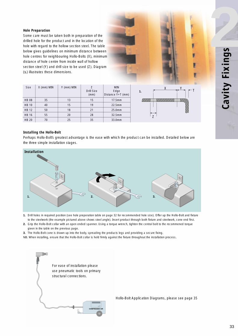
Installing the Hollo-BoltPerhaps Hollo-Bolt’s greatest advantage is the ease with which the product can be installed. Detailed below arethe three simple installation stages.
Installation
1. Drill holes in required position (see hole preperation table on page 32 for recommended hole size). Offer up the Hollo-Bolt and fixture to the steelwork (the example pictured above shows steel angle). Insert product through both fixture and steelwork, cone end first.
2. Grip the Hollo-Bolt collar with an open ended spanner. Using a torque wrench, tighten the central bolt to the recommened torque given in the table on the previous page.
3. The Hollo-Bolt cone is drawn up into the body, spreading the products legs and providing a secure fixing.NB. When installing, ensure that the Hollo-Bolt collar is held firmly against the fixture throughout the installation process.
33
Cavi
ty F
ixin
gs
2Hole PreparationSome care must be taken both in preparation of thedrilled hole for the product and in the location of thehole with regard to the hollow section steel. The tablebelow gives guidelines on minimum distance betweenhole centres for neighbouring Hollo-Bolts (X), minimumdistance of hole centre from inside wall of hollowsection steel (Y) and drill size to be used (Z). Diagram(1.) illustrates these dimensions.
Size X (mm) MIN Y (mm) MIN Z MINDrill Size Edge
(mm) Distance Y+T (mm)
HB 08 35 13 15 17.5mm
HB 10 40 15 19 22.5mm
HB 12 50 18 21 25.0mm
HB 16 55 20 28 32.5mm
HB 20 70 25 35 33.0mm
For Hollo-Bolt Application Diagrams, please see page 35
X YT
Z
For ease of installation pleaseuse pneumatic tools on primarystructural connections.
1. 2. 3.
1.
34
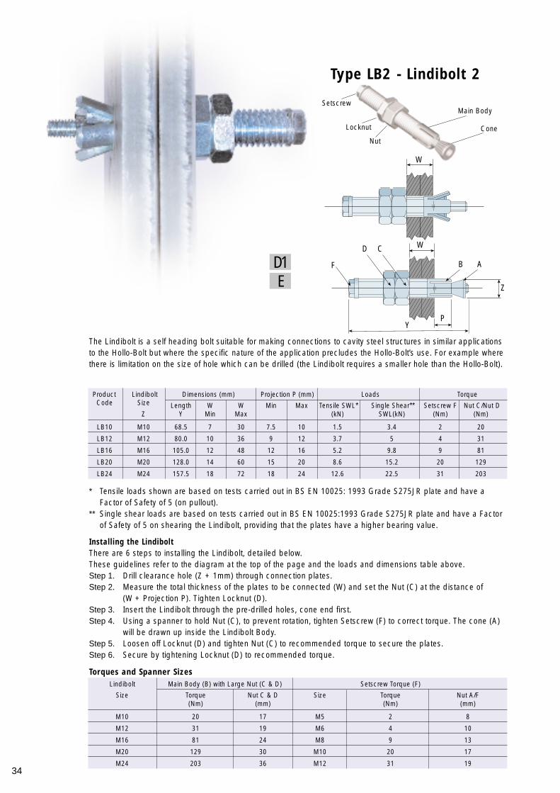
The Lindibolt is a self heading bolt suitable for making connections to cavity steel structures in similar applicationsto the Hollo-Bolt but where the specific nature of the application precludes the Hollo-Bolt’s use. For example wherethere is limitation on the size of hole which can be drilled (the Lindibolt requires a smaller hole than the Hollo-Bolt).
* Tensile loads shown are based on tests carried out in BS EN 10025: 1993 Grade S275JR plate and have a Factor of Safety of 5 (on pullout).
** Single shear loads are based on tests carried out in BS EN 10025:1993 Grade S275JR plate and have a Factor of Safety of 5 on shearing the Lindibolt, providing that the plates have a higher bearing value.
Installing the LindiboltThere are 6 steps to installing the Lindibolt, detailed below.These guidelines refer to the diagram at the top of the page and the loads and dimensions table above.Step 1. Drill clearance hole (Z + 1mm) through connection plates.Step 2. Measure the total thickness of the plates to be connected (W) and set the Nut (C) at the distance of
(W + Projection P). Tighten Locknut (D).Step 3. Insert the Lindibolt through the pre-drilled holes, cone end first.Step 4. Using a spanner to hold Nut (C), to prevent rotation, tighten Setscrew (F) to correct torque. The cone (A)
will be drawn up inside the Lindibolt Body.Step 5. Loosen off Locknut (D) and tighten Nut (C) to recommended torque to secure the plates.Step 6. Secure by tightening Locknut (D) to recommended torque.
Type LB2 - Lindibolt 2
Product Lindibolt Dimensions (mm) Projection P (mm) Loads TorqueCode Size Length W W Min Max Tensile SWL* Single Shear** Setscrew F Nut C/Nut D
Z Y Min Max (kN) SWL(kN) (Nm) (Nm)
LB10 M10 68.5 7 30 7.5 10 1.5 3.4 2 20
LB12 M12 80.0 10 36 9 12 3.7 5 4 31
LB16 M16 105.0 12 48 12 16 5.2 9.8 9 81
LB20 M20 128.0 14 60 15 20 8.6 15.2 20 129
LB24 M24 157.5 18 72 18 24 12.6 22.5 31 203
Lindibolt Main Body (B) with Large Nut (C & D) Setscrew Torque (F)
Size Torque Nut C & D Size Torque Nut A/F(Nm) (mm) (Nm) (mm)
M10 20 17 M5 2 8
M12 31 19 M6 4 10
M16 81 24 M8 9 13
M20 129 30 M10 20 17
M24 203 36 M12 31 19
W
F
D C
B A
Z
PY
W
Torques and Spanner Sizes
Main Body
Cone
Nut
Locknut
Setscrew
ED1
35
Cavi
ty F
ixin
gs
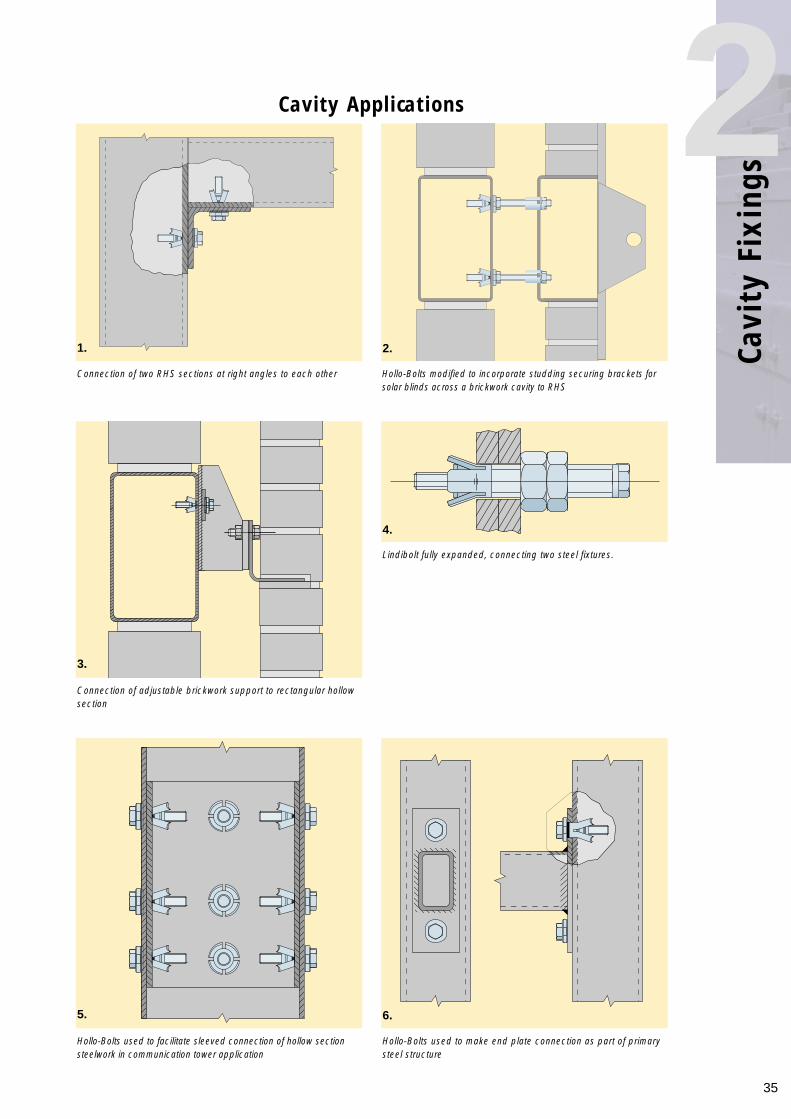
2Cavity Applications
Connection of two RHS sections at right angles to each other
Lindibolt fully expanded, connecting two steel fixtures.
Hollo-Bolts used to facilitate sleeved connection of hollow sectionsteelwork in communication tower application
Hollo-Bolts used to make end plate connection as part of primarysteel structure
Connection of adjustable brickwork support to rectangular hollowsection
Hollo-Bolts modified to incorporate studding securing brackets forsolar blinds across a brickwork cavity to RHS
1. 2.
3.
4.
5. 6.

Lindapter’s close working relationship with leadingorganisations such as London Underground Ltdleads to an involvement in many bespoke projects.Lindapter’s engineers are able to work with acomplex brief and offer a design to meet thecustomer’s requirements, seeing it throughprototyping to finished design and finally tomanufactured items. Many of these designs offer areduction in installation time for new rails, ensuringearly delivery of the benefits from improved trackconfiguration.
In addition to this bespoke service, Lindapter alsooffers a range of rail clips to suit many standardapplications. Many of these offer the most cost-effective method of fixing the rails to the sleepers,as well as proving easier and less time-consumingto fit than other types of clip which require weldingto the sleepers.
The main family of rail clips is the Holdfast range. Allof which facilitate precise alignment of rails byallowing a high degree of stepless lateraladjustability. This alignment helps alleviate some ofthe problems that occur in track running machineryas a result of misalignment, such as excessivewheel, gearbox or bearing wear. The other productsin the range are the type BR Rail Clip and theForged Steel Rail Clip (RC) although none aresuitable for high-speed applications.
Rail Fixings
36
Rail Fixings ContentsIntroduction to Rail Fixings 36Type BR - Rail Clips 37Type RC - Forged Steel Rail Clips 37Rail Clip Applications 37Type HD - Holdfast 38Holdfast Installation 39
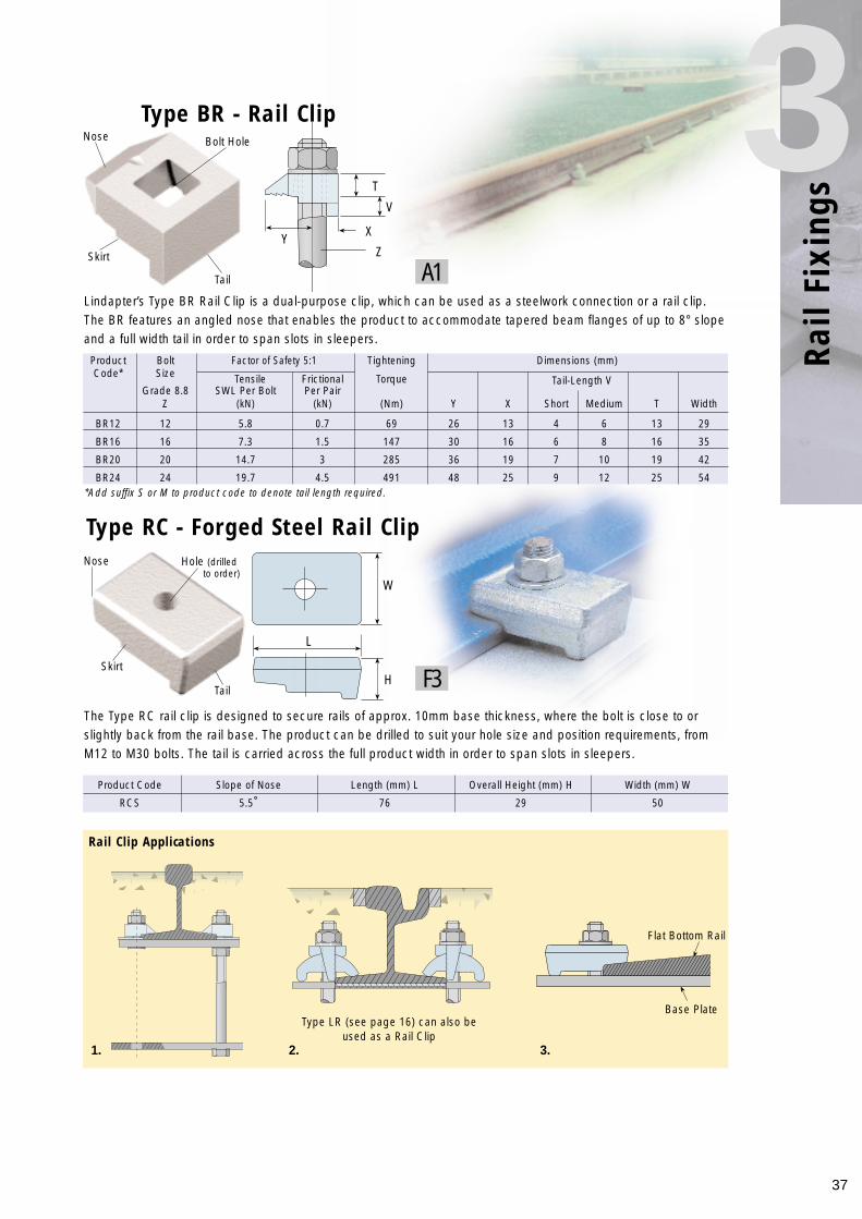
Type BR - Rail Clip
Product Bolt Factor of Safety 5:1 Tightening Dimensions (mm)Code* Size Tensile Frictional Torque Tail-Length V
Grade 8.8 SWL Per Bolt Per PairZ (kN) (kN) (Nm) Y X Short Medium T Width
BR12 12 5.8 0.7 69 26 13 4 6 13 29
BR16 16 7.3 1.5 147 30 16 6 8 16 35
BR20 20 14.7 3 285 36 19 7 10 19 42
BR24 24 19.7 4.5 491 48 25 9 12 25 54
Lindapter’s Type BR Rail Clip is a dual-purpose clip, which can be used as a steelwork connection or a rail clip.The BR features an angled nose that enables the product to accommodate tapered beam flanges of up to 8° slopeand a full width tail in order to span slots in sleepers.
37
Rail
Fixi
ngs
3
Type RC - Forged Steel Rail Clip
Product Code Slope of Nose Length (mm) L Overall Height (mm) H Width (mm) W
RCS 5.5˚ 76 29 50
The Type RC rail clip is designed to secure rails of approx. 10mm base thickness, where the bolt is close to orslightly back from the rail base. The product can be drilled to suit your hole size and position requirements, fromM12 to M30 bolts. The tail is carried across the full product width in order to span slots in sleepers.
*Add suffix S or M to product code to denote tail length required.
Rail Clip Applications
T
V
X
ZY
Nose
Nose
Tail
W
H
L
Skirt
Flat Bottom Rail
Base Plate
Hole (drilledto order)
Skirt
Tail
Bolt Hole
Type LR (see page 16) can also beused as a Rail Clip
A1
F3
1. 2. 3.
38
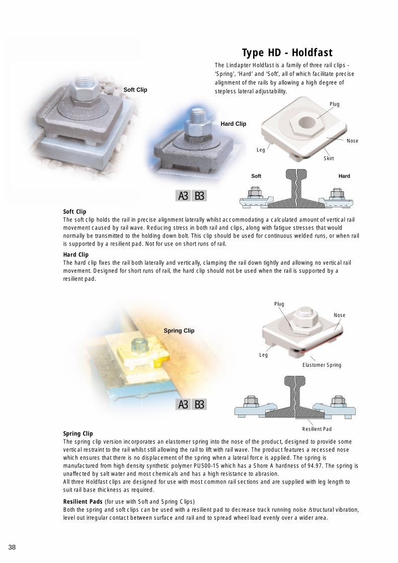
Type HD - Holdfast
Soft ClipThe soft clip holds the rail in precise alignment laterally whilst accommodating a calculated amount of vertical railmovement caused by rail wave. Reducing stress in both rail and clips, along with fatigue stresses that wouldnormally be transmitted to the holding down bolt. This clip should be used for continuous welded runs, or when railis supported by a resilient pad. Not for use on short runs of rail.
Hard ClipThe hard clip fixes the rail both laterally and vertically, clamping the rail down tightly and allowing no vertical railmovement. Designed for short runs of rail, the hard clip should not be used when the rail is supported by aresilient pad.
Spring ClipThe spring clip version incorporates an elastomer spring into the nose of the product, designed to provide somevertical restraint to the rail whilst still allowing the rail to lift with rail wave. The product features a recessed nosewhich ensures that there is no displacement of the spring when a lateral force is applied. The spring ismanufactured from high density synthetic polymer PU500-15 which has a Shore A hardness of 94.97. The spring isunaffected by salt water and most chemicals and has a high resistance to abrasion. All three Holdfast clips are designed for use with most common rail sections and are supplied with leg length tosuit rail base thickness as required.
Resilient Pads (for use with Soft and Spring Clips)Both the spring and soft clips can be used with a resilient pad to decrease track running noise /structural vibration,level out irregular contact between surface and rail and to spread wheel load evenly over a wider area.
The Lindapter Holdfast is a family of three rail clips -‘Spring’, ‘Hard’ and ‘Soft’, all of which facilitate precisealignment of the rails by allowing a high degree ofstepless lateral adjustability.
Skirt
Leg
Leg
Elastomer Spring
Resilient Pad
Soft Hard
Nose
Nose
Plug
Plug
Soft Clip
Hard Clip
Spring Clip
B3A3
B3A3
39
Rail
Fixi
ngs
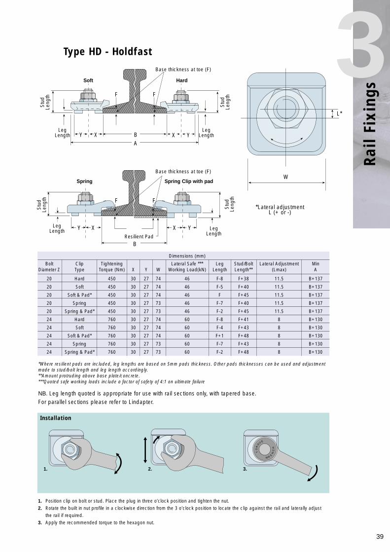
3Type HD - Holdfast
NB. Leg length quoted is appropriate for use with rail sections only, with tapered base.For parallel sections please refer to Lindapter.
Dimensions (mm)
Bolt Clip Tightening Lateral Safe *** Leg Stud/Bolt Lateral Adjustment MinDiameter Z Type Torque (Nm) X Y W Working Load(kN) Length Length** (Lmax) A
20 Hard 450 30 27 74 46 F-8 F+38 11.5 B+137
20 Soft 450 30 27 74 46 F-5 F+40 11.5 B+137
20 Soft & Pad* 450 30 27 74 46 F F+45 11.5 B+137
20 Spring 450 30 27 73 46 F-7 F+40 11.5 B+137
20 Spring & Pad* 450 30 27 73 46 F-2 F+45 11.5 B+137
24 Hard 760 30 27 74 60 F-8 F+41 8 B+130
24 Soft 760 30 27 74 60 F-4 F+43 8 B+130
24 Soft & Pad* 760 30 27 74 60 F+1 F+48 8 B+130
24 Spring 760 30 27 73 60 F-7 F+43 8 B+130
24 Spring & Pad* 760 30 27 73 60 F-2 F+48 8 B+130
*Where resilient pads are included, leg lengths are based on 5mm pads thickness. Other pads thicknesses can be used and adjustmentmade to stud/bolt length and leg length accordingly.**Amount protruding above base plate/concrete.***Quoted safe working loads include a factor of safety of 4:1 on ultimate failure
Installation
1. Position clip on bolt or stud. Place the plug in three o’clock position and tighten the nut.2. Rotate the built in nut profile in a clockwise direction from the 3 o’clock position to locate the clip against the rail and laterally adjust
the rail if required.3. Apply the recommended torque to the hexagon nut.
R
E
W
Q
U
TO
R
NE
HC
Y X X YLeg
Length
LegLength Leg
Length
W
*Lateral adjustment L (+ or -)
L*
Resilient Pad
LegLength
Soft
Spring Spring Clip with pad
Hard
Base thickness at toe (F)
Base thickness at toe (F)
Stud
Leng
th
Stud
Leng
thY X X Y
BA
F F
F F
B
1. 2. 3.
Stud
Leng
th
Stud
Leng
th
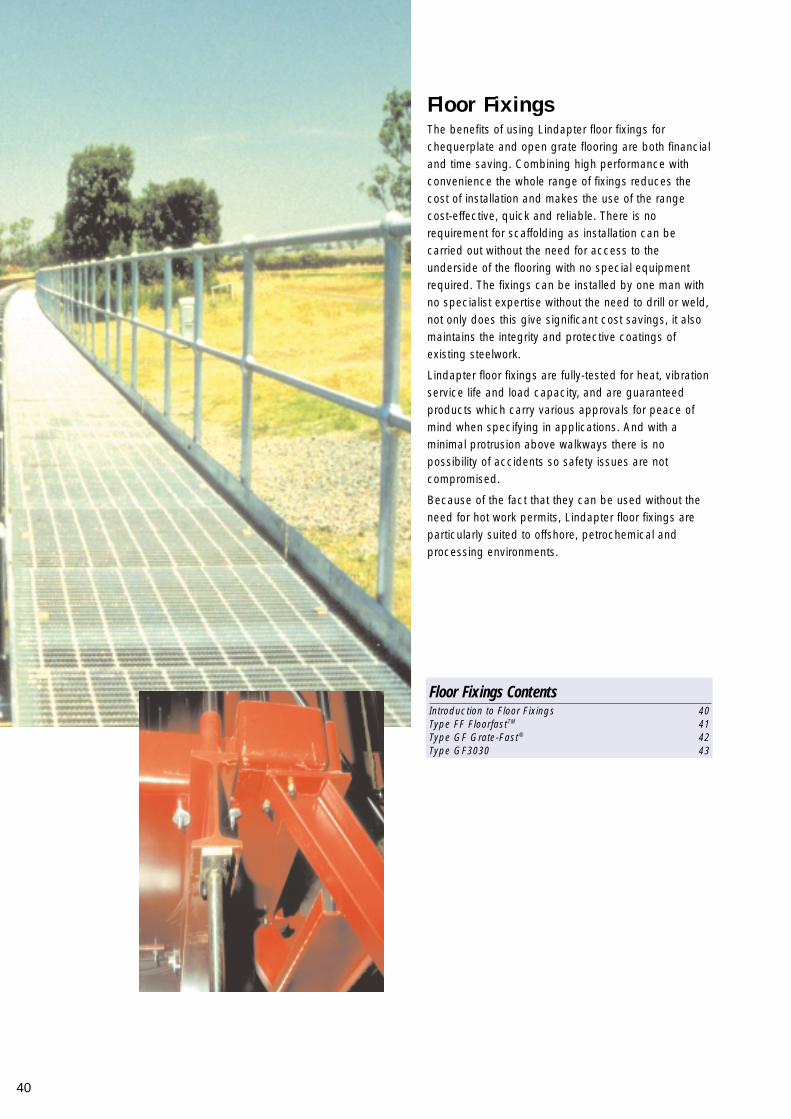
The benefits of using Lindapter floor fixings forchequerplate and open grate flooring are both financialand time saving. Combining high performance withconvenience the whole range of fixings reduces thecost of installation and makes the use of the rangecost-effective, quick and reliable. There is norequirement for scaffolding as installation can becarried out without the need for access to theunderside of the flooring with no special equipmentrequired. The fixings can be installed by one man withno specialist expertise without the need to drill or weld,not only does this give significant cost savings, it alsomaintains the integrity and protective coatings ofexisting steelwork.
Lindapter floor fixings are fully-tested for heat, vibrationservice life and load capacity, and are guaranteedproducts which carry various approvals for peace ofmind when specifying in applications. And with aminimal protrusion above walkways there is nopossibility of accidents so safety issues are notcompromised.
Because of the fact that they can be used without theneed for hot work permits, Lindapter floor fixings areparticularly suited to offshore, petrochemical andprocessing environments.
Floor Fixings
40
Floor Fixings ContentsIntroduction to Floor Fixings 40Type FF FloorfastTM 41Type GF Grate-Fast® 42Type GF3030 43
41
Floo
r Fi
s4
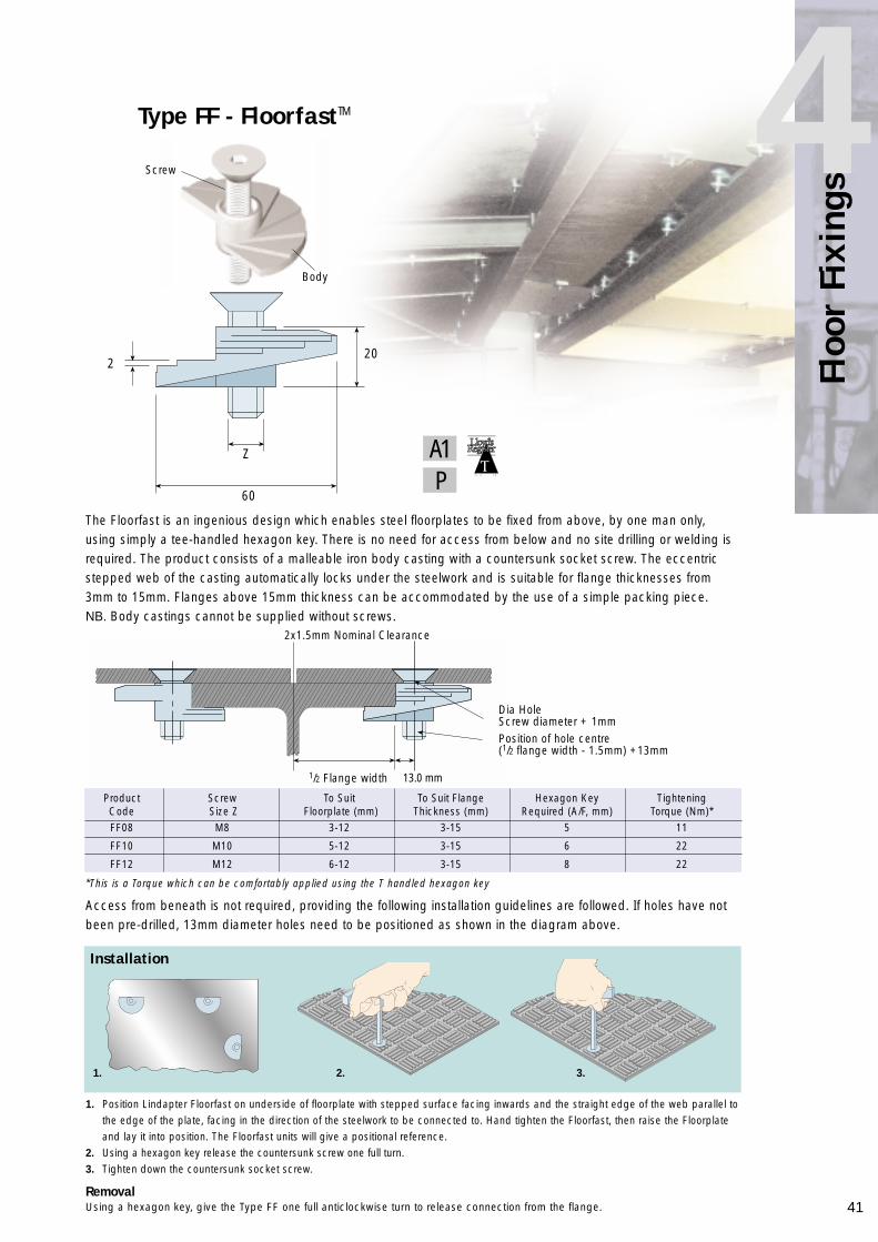
The Floorfast is an ingenious design which enables steel floorplates to be fixed from above, by one man only,using simply a tee-handled hexagon key. There is no need for access from below and no site drilling or welding isrequired. The product consists of a malleable iron body casting with a countersunk socket screw. The eccentricstepped web of the casting automatically locks under the steelwork and is suitable for flange thicknesses from3mm to 15mm. Flanges above 15mm thickness can be accommodated by the use of a simple packing piece.NB. Body castings cannot be supplied without screws.
Product Screw To Suit To Suit Flange Hexagon Key TighteningCode Size Z Floorplate (mm) Thickness (mm) Required (A/F, mm) Torque (Nm)*FF08 M8 3-12 3-15 5 11
FF10 M10 5-12 3-15 6 22
FF12 M12 6-12 3-15 8 22
Installation
1. Position Lindapter Floorfast on underside of floorplate with stepped surface facing inwards and the straight edge of the web parallel tothe edge of the plate, facing in the direction of the steelwork to be connected to. Hand tighten the Floorfast, then raise the Floorplate and lay it into position. The Floorfast units will give a positional reference.
2. Using a hexagon key release the countersunk screw one full turn.3. Tighten down the countersunk socket screw.
RemovalUsing a hexagon key, give the Type FF one full anticlockwise turn to release connection from the flange.
Access from beneath is not required, providing the following installation guidelines are followed. If holes have notbeen pre-drilled, 13mm diameter holes need to be positioned as shown in the diagram above.
Type FF - FloorfastTM
220
Z
60
Screw
Body
2x1.5mm Nominal Clearance
Dia HoleScrew diameter + 1mmPosition of hole centre(1/2 flange width - 1.5mm) +13mm
1/2 Flange width 13.0 mm
1. 2. 3.
A1P
*This is a Torque which can be comfortably applied using the T handled hexagon key
42
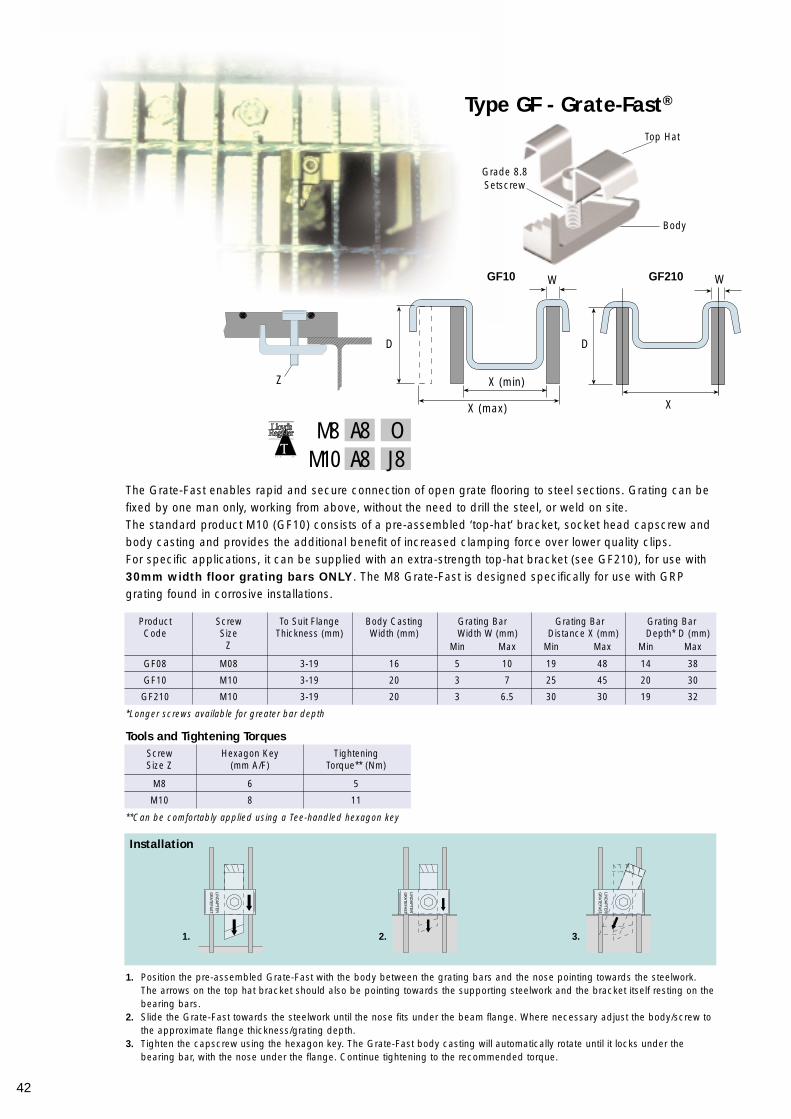
Type GF - Grate-Fast®
The Grate-Fast enables rapid and secure connection of open grate flooring to steel sections. Grating can befixed by one man only, working from above, without the need to drill the steel, or weld on site.The standard product M10 (GF10) consists of a pre-assembled ‘top-hat’ bracket, socket head capscrew andbody casting and provides the additional benefit of increased clamping force over lower quality clips.For specific applications, it can be supplied with an extra-strength top-hat bracket (see GF210), for use with30mm width floor grating bars ONLY. The M8 Grate-Fast is designed specifically for use with GRPgrating found in corrosive installations.
Product Screw To Suit Flange Body Casting Grating Bar Grating Bar Grating BarCode Size Thickness (mm) Width (mm) Width W (mm) Distance X (mm) Depth* D (mm)
Z Min Max Min Max Min Max
GF08 M08 3-19 16 5 10 19 48 14 38
GF10 M10 3-19 20 3 7 25 45 20 30
GF210 M10 3-19 20 3 6.5 30 30 19 32
Installation
1. Position the pre-assembled Grate-Fast with the body between the grating bars and the nose pointing towards the steelwork. The arrows on the top hat bracket should also be pointing towards the supporting steelwork and the bracket itself resting on thebearing bars.
2. Slide the Grate-Fast towards the steelwork until the nose fits under the beam flange. Where necessary adjust the body/screw to the approximate flange thickness/grating depth.
3. Tighten the capscrew using the hexagon key. The Grate-Fast body casting will automatically rotate until it locks under the bearing bar, with the nose under the flange. Continue tightening to the recommended torque.
*Longer screws available for greater bar depth
**Can be comfortably applied using a Tee-handled hexagon key
Screw Hexagon Key TighteningSize Z (mm A/F) Torque** (Nm)
M8 6 5
M10 8 11
Tools and Tightening Torques
Grade 8.8Setscrew
Body
Top Hat
W
D D
W
XX (max)
X (min)
GF210GF10
1. 2. 3.
OA8J8A8M10
M8
Z

43
Floo
r Fi
s4
Installation
1. Position the fixing with the grating bar located between the two tabs on the upper profile, facing towards the supporting steelwork.2. Apply a downward force to the fixing, so that the lower leg passes through the grating.3. Apply a downward force to the top of the fixing, with the sole of the foot, or a hammer. The fixing then snaps into place, flush with the
grating deck. If the lower profile contacts the steelwork web, the GF3030 will automatically relocate itself, locking onto the first tab.
Type GF3030
The GF3030 is a groundbreaking product that enables the connection of European style 30 x 30 floor grating tosteel sections. The product’s ingenuity lies in its place and stand installation method, which can be carried out byone person only, working from above, without the need to drill or weld. Not only does this give significant costsavings, but maintains the integrity of existing steelwork.The GF3030 is designed specifically for use with 30mm depth floor grating. It is however possible to use theproduct on other grating depths, providing the total fixing thickness (grating depth + steelwork flange thickness) isbetween 38mm (minimum) and 48mm (maximum). The steelwork flange thickness range is 8mm to 18mm. Forfurther details, please contact Lindapter.NB. The Type GF3030 is not suitable for sloping flanges.
Grating Depth Steel Flange Total Clamping Thickness Clamping (mm) Thickness (mm) (mm) (Grating Depth and Force per
Steelwork Flange Thickness) Clip (N)30 8 38 34030 13 43 53030 18 48 680
Clamping Force Examples
RemovalRemoving the GF3030 after installation is simple - using a screwdriver or lever, raise the back of the GF3030 intoposition shown in diagram 2. Place the lever between the steelwork and lower leg of the fixing and prise GF3030away from the steelwork. NB. After removing the GF3030, it is essential that it is inspected for deformation or wear prior to re-use
Upper Profile
Lower Leg
1. 2. 3.
G4
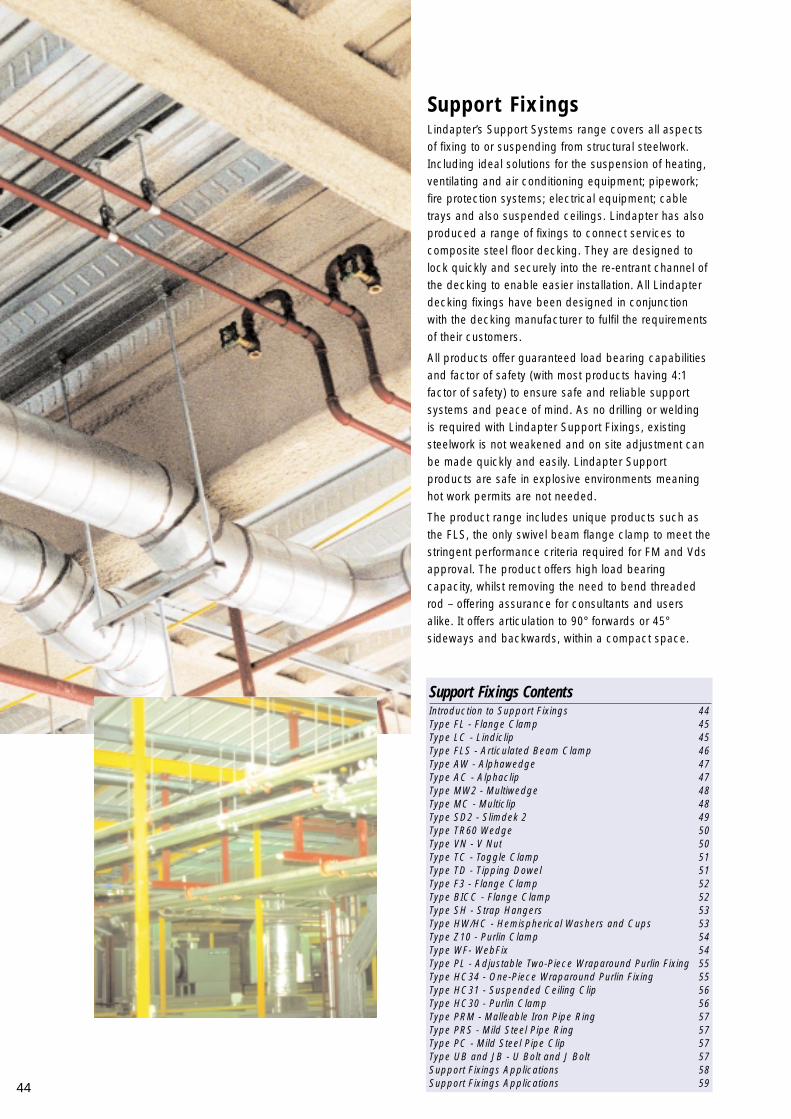
Lindapter’s Support Systems range covers all aspectsof fixing to or suspending from structural steelwork.Including ideal solutions for the suspension of heating,ventilating and air conditioning equipment; pipework;fire protection systems; electrical equipment; cabletrays and also suspended ceilings. Lindapter has alsoproduced a range of fixings to connect services tocomposite steel floor decking. They are designed tolock quickly and securely into the re-entrant channel ofthe decking to enable easier installation. All Lindapterdecking fixings have been designed in conjunctionwith the decking manufacturer to fulfil the requirementsof their customers.
All products offer guaranteed load bearing capabilitiesand factor of safety (with most products having 4:1factor of safety) to ensure safe and reliable supportsystems and peace of mind. As no drilling or weldingis required with Lindapter Support Fixings, existingsteelwork is not weakened and on site adjustment canbe made quickly and easily. Lindapter Supportproducts are safe in explosive environments meaninghot work permits are not needed.
The product range includes unique products such asthe FLS, the only swivel beam flange clamp to meet thestringent performance criteria required for FM and Vdsapproval. The product offers high load bearingcapacity, whilst removing the need to bend threadedrod – offering assurance for consultants and usersalike. It offers articulation to 90° forwards or 45°sideways and backwards, within a compact space.
Support Fixings
44
Support Fixings ContentsIntroduction to Support Fixings 44Type FL - Flange Clamp 45Type LC - Lindiclip 45Type FLS - Articulated Beam Clamp 46Type AW - Alphawedge 47Type AC - Alphaclip 47Type MW2 - Multiwedge 48Type MC - Multiclip 48Type SD2 - Slimdek 2 49Type TR60 Wedge 50Type VN - V Nut 50Type TC - Toggle Clamp 51Type TD - Tipping Dowel 51Type F3 - Flange Clamp 52Type BICC - Flange Clamp 52Type SH - Strap Hangers 53Type HW/HC - Hemispherical Washers and Cups 53Type Z10 - Purlin Clamp 54Type WF- WebFix 54Type PL - Adjustable Two-Piece Wraparound Purlin Fixing 55Type HC34 - One-Piece Wraparound Purlin Fixing 55Type HC31 - Suspended Ceiling Clip 56Type HC30 - Purlin Clamp 56Type PRM - Malleable Iron Pipe Ring 57Type PRS - Mild Steel Pipe Ring 57Type PC - Mild Steel Pipe Clip 57Type UB and JB - U Bolt and J Bolt 57Support Fixings Applications 58Support Fixings Applications 59

45
Supp
ort
Fixi
ngs
5The simplest, quickest and most cost-effective method of suspending building services from steel beams andsuitable for use with parallel or tapered flange beams, the FL can be supplied with the back hole drilled to accepta plain rod or tapped to accept a threaded rod. The FL uses a grade 8.8 cup point setscrew to provide maximumbite into steelwork and maximum load performance.
Installation1. Slide FL onto beam flange and tighten setscrew to recommended torque. To avoid over tightening, a rough
guide to achieve the correct torque is to tighten the setscrew with thumb and forefinger and then apply a furtherquarter turn (90˚) with a spanner. When used with taper flanges it is important to ensure that the setscrew of theFL bites into the tapered face of the flange, rather than the parallel underside.
2. Tighten the locknut to the recommended torque.NB. A Flange Clamp with a Hexagon Head is now available dependent on quantity, please contact Lindapter for details.
*Product Drop Tensile Loads Setscrew LocknutCode Rod Safe Working Torque (Nm) Torque (Nm) T U V W X Y Z
Load 4:1(kN)
FL16 M6 1.1 8 11 36 35 19 17 20 7 8
FL18 M8 1.1 8 11 36 35 19 17 20 9 8
FL210 M10 2.4 8 22 45 40 22 19 22 11 10
FL312 M12 3.1 8 22 50 46 25 23 28 13 10
FL412 M12 3.1 8 22 53 51 26 28 27 13 10
Installation as with Type FL
Type FL - Flange Clamp
A1
Designed to carry lighter loads than the FL or F3 products, the Lindiclip is supplied assembled with an M6 case-hardened cup point setscrew and locknut and will accept threaded rod or cable clips. Standard specification is forboth holes to be tapped M6, but M8 is available as an option.
Product Code Loads Tensile (kN) Setscrew Torque Locknut Torque Dimensions (mm)Factor of safety of 4:1
Tensile X Tensile Y (Nm) (Nm) W X Y
LCLIP 0.18 0.59 4 4.5 20 6 6
Type LC - Lindiclip
Installation
T
V
U
W
Y
X
ZZ
W
X Y
Setscrew
LocknutBody
SetscrewRear Hole(Tapped or Clear)
Locknut
Jaws
Body
A1
On applications supporting pipework above 65mmbore the additional safety strip should be used.NOTE: This style of safety bracket can also be used ontapered flanges. Please contact Lindapter for details.
✗
✓
✓
✓
✓
✓
✓
✗
Parallel Flanges Taper Flanges
* add T or P suffix to indicate preference of plain or tapped hole.
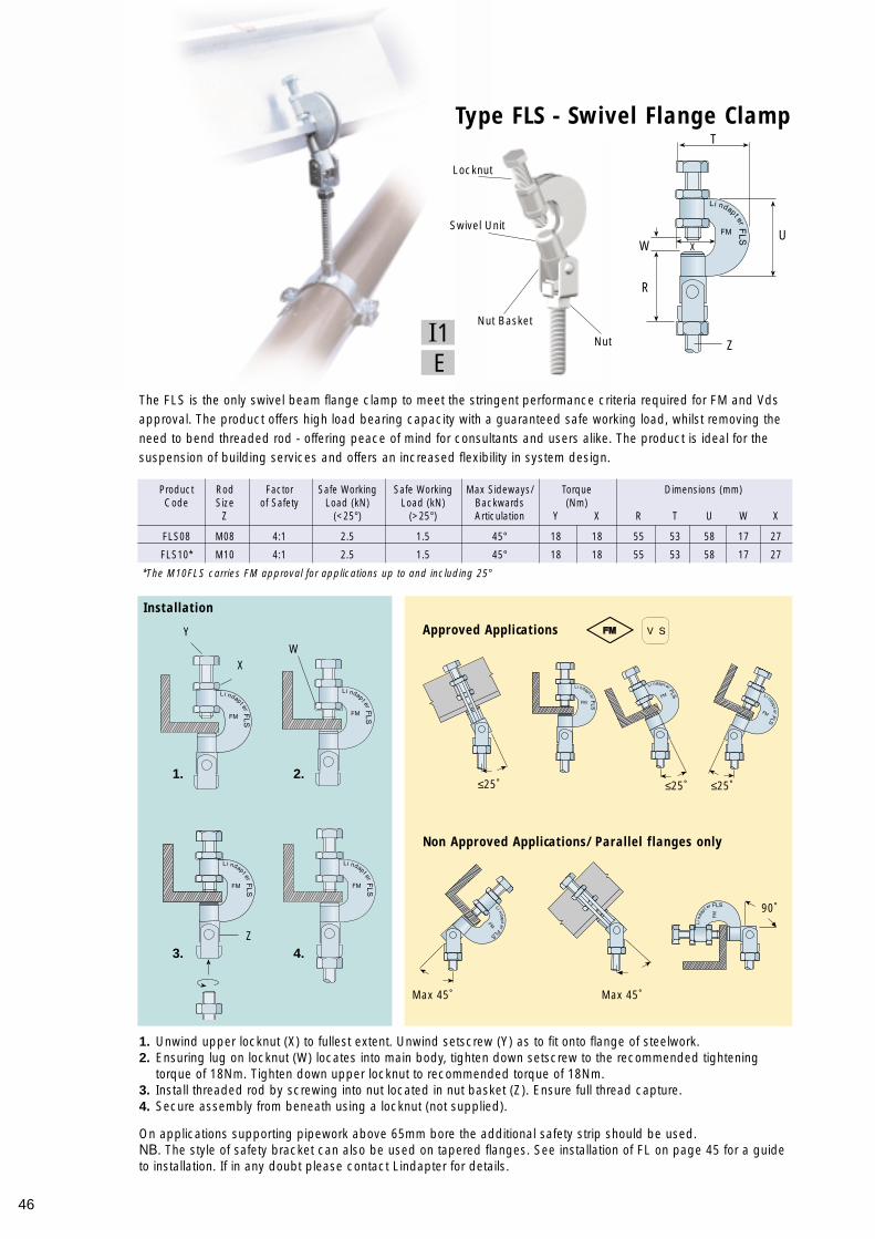
46
The FLS is the only swivel beam flange clamp to meet the stringent performance criteria required for FM and Vdsapproval. The product offers high load bearing capacity with a guaranteed safe working load, whilst removing theneed to bend threaded rod - offering peace of mind for consultants and users alike. The product is ideal for thesuspension of building services and offers an increased flexibility in system design.
1. Unwind upper locknut (X) to fullest extent. Unwind setscrew (Y) as to fit onto flange of steelwork.2. Ensuring lug on locknut (W) locates into main body, tighten down setscrew to the recommended tightening
torque of 18Nm. Tighten down upper locknut to recommended torque of 18Nm.3. Install threaded rod by screwing into nut located in nut basket (Z). Ensure full thread capture.4. Secure assembly from beneath using a locknut (not supplied).
On applications supporting pipework above 65mm bore the additional safety strip should be used.NB. The style of safety bracket can also be used on tapered flanges. See installation of FL on page 45 for a guideto installation. If in any doubt please contact Lindapter for details.
Type FLS - Swivel Flange Clamp
Product Rod Factor Safe Working Safe Working Max Sideways/ Torque Dimensions (mm)Code Size of Safety Load (kN) Load (kN) Backwards (Nm)
Z (<25°) (>25°) Articulation Y X R T U W X
FLS08 M08 4:1 2.5 1.5 45° 18 18 55 53 58 17 27
FLS10* M10 4:1 2.5 1.5 45° 18 18 55 53 58 17 27
Approved Applications
Non Approved Applications/Parallel flanges only
*The M10FLS carries FM approval for applications up to and including 25°
Installation
EI1
1. 2.
3. 4.
YW
X
Z
T
U
R
Z
W X
Locknut
Swivel Unit
Nut Basket
Nut
≤25˚ ≤25˚
Max 45˚ Max 45˚
≤25˚
90˚
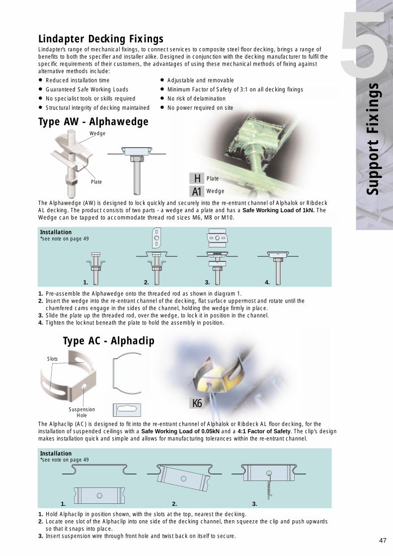
47
Supp
ort
Fixi
ngs
5
1. Hold Alphaclip in position shown, with the slots at the top, nearest the decking.2. Locate one slot of the Alphaclip into one side of the decking channel, then squeeze the clip and push upwards
so that it snaps into place.3. Insert suspension wire through front hole and twist back on itself to secure.
The Alphawedge (AW) is designed to lock quickly and securely into the re-entrant channel of Alphalok or RibdeckAL decking. The product consists of two parts - a wedge and a plate and has a Safe Working Load of 1kN. TheWedge can be tapped to accommodate thread rod sizes M6, M8 or M10.
1. Pre-assemble the Alphawedge onto the threaded rod as shown in diagram 1.2. Insert the wedge into the re-entrant channel of the decking, flat surface uppermost and rotate until the
chamfered cams engage in the sides of the channel, holding the wedge firmly in place.3. Slide the plate up the threaded rod, over the wedge, to lock it in position in the channel.4. Tighten the locknut beneath the plate to hold the assembly in position.
Type AW - Alphawedge
Lindapter Decking Fixings
Type AC - Alphaclip
Installation
Installation
HA1
K6
1. 2. 3. 4.
1. 2. 3.
Plate
SuspensionHole
Slots
Wedge
The Alphaclip (AC) is designed to fit into the re-entrant channel of Alphalok or Ribdeck AL floor decking, for theinstallation of suspended ceilings with a Safe Working Load of 0.05kN and a 4:1 Factor of Safety. The clip’s designmakes installation quick and simple and allows for manufacturing tolerances within the re-entrant channel.
Lindapter’s range of mechanical fixings, to connect services to composite steel floor decking, brings a range ofbenefits to both the specifier and installer alike. Designed in conjunction with the decking manufacturer to fulfil thespecific requirements of their customers, the advantages of using these mechanical methods of fixing againstalternative methods include:
• Reduced installation time • Adjustable and removable
• Guaranteed Safe Working Loads • Minimum Factor of Safety of 3:1 on all decking fixings
• No specialist tools or skills required • No risk of delamination
• Structural integrity of decking maintained • No power required on site
Plate
Wedge
*see note on page 49
*see note on page 49
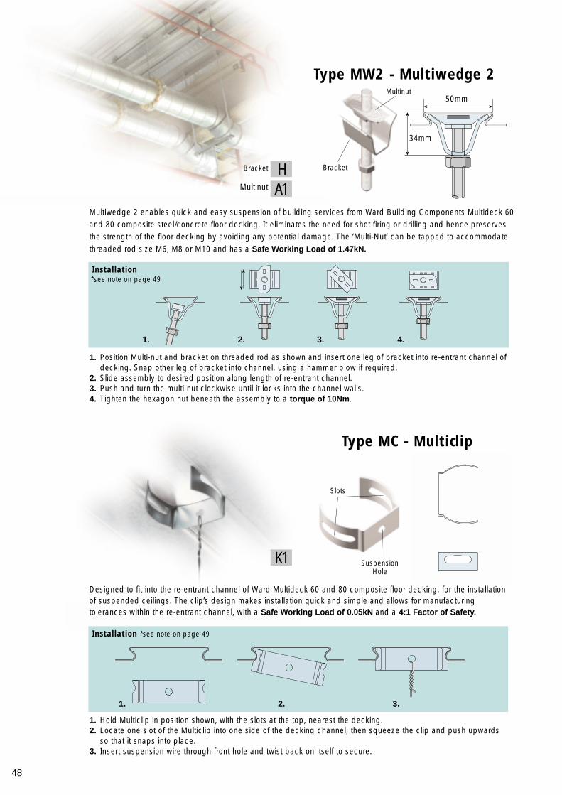
48
Designed to fit into the re-entrant channel of Ward Multideck 60 and 80 composite floor decking, for the installationof suspended ceilings. The clip’s design makes installation quick and simple and allows for manufacturingtolerances within the re-entrant channel, with a Safe Working Load of 0.05kN and a 4:1 Factor of Safety.
1. Hold Multiclip in position shown, with the slots at the top, nearest the decking.2. Locate one slot of the Multiclip into one side of the decking channel, then squeeze the clip and push upwards
so that it snaps into place.3. Insert suspension wire through front hole and twist back on itself to secure.
1. Position Multi-nut and bracket on threaded rod as shown and insert one leg of bracket into re-entrant channel ofdecking. Snap other leg of bracket into channel, using a hammer blow if required.
2. Slide assembly to desired position along length of re-entrant channel.3. Push and turn the multi-nut clockwise until it locks into the channel walls.4. Tighten the hexagon nut beneath the assembly to a torque of 10Nm.
Type MC - Multiclip
Installation
Installation *see note on page 49
Multiwedge 2 enables quick and easy suspension of building services from Ward Building Components Multideck 60and 80 composite steel/concrete floor decking. It eliminates the need for shot firing or drilling and hence preservesthe strength of the floor decking by avoiding any potential damage. The ‘Multi-Nut’ can be tapped to accommodatethreaded rod size M6, M8 or M10 and has a Safe Working Load of 1.47kN.
A1H
K1
1. 2. 3. 4.
Type MW2 - Multiwedge 2
1. 2. 3.
Bracket
Multinut50mm
34mm
SuspensionHole
Slots
Bracket
Multinut
*see note on page 49
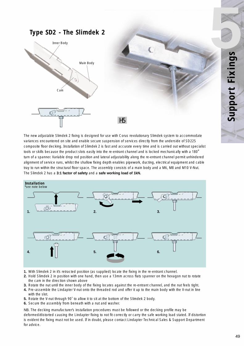
49
The new adjustable Slimdek 2 fixing is designed for use with Corus revolutionary Slimdek system to accommodatevariances encountered on site and enable secure suspension of services directly from the underside of SD225composite floor decking. Installation of Slimdek 2 is fast and accurate every time and is carried out without specialisttools or skills because the product slots easily into the re-entrant channel and is locked mechanically with a 180˚turn of a spanner. Variable drop rod position and lateral adjustability along the re-entrant channel permit unhinderedalignment of service runs, whilst the shallow fixing depth enables pipework, ducting, electrical equipment and cabletray to run within the structural floor space. The assembly consists of a main body and a M6, M8 and M10 V-Nut.The Slimdek 2 has a 3:1 factor of safety and a safe working load of 1kN.
1. With Slimdek 2 in it’s retracted position (as supplied) locate the fixing in the re-entrant channel.2. Hold Slimdek 2 in position with one hand, then use a 13mm across flats spanner on the hexagon nut to rotate
the cam in the direction shown above3. Rotate the nut until the inner body of the fixing locates against the re-entrant channel, and the nut feels tight.4. Pre–assemble the Lindapter V-nut onto the threaded rod and offer it up to the main body with the V-nut in line
with the slot.5. Rotate the V-nut through 90˚ to allow it to sit at the bottom of the Slimdek 2 body. 6. Secure the assembly from beneath with a nut and washer.
Installation
Supp
ort
Fixi
ngs
5Type SD2 - The Slimdek 2
H5
1. 2. 3.
4. 5. 6.
Main Body
Cam
Inner Body
NB. The decking manufacturer’s installation procedures must be followed or the decking profile may bedeformed/distorted causing the Lindapter fixing to not fit correctly or carry the safe working load stated. If distortionis evident the fixing must not be used. If in doubt, please contact Lindapter Technical Sales & Support Departmentfor advice.
*see note below
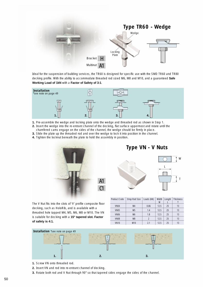
50
Ideal for the suspension of building services, the TR60 is designed for specific use with the SMD TR60 and TR80decking profile. With the ability to accommodate threaded rod sized M6, M8 and M10, and a guaranteed SafeWorking Load of 1kN with a Factor of Safety of 3:1.
1. Pre-assemble the wedge and locking plate onto the wedge and threaded rod as shown in Step 1.2. Insert the wedge into the re-entrant channel of the decking, flat surface uppermost and rotate until the
chamfered cams engage on the sides of the channel, the wedge should be firmly in place.3. Slide the plate up the threaded rod and over the wedge to lock it into position in the channel.4. Tighten the locknut beneath the plate to hold the assembly in position.
The V Nut fits into the slots of ‘V’ profile composite floordecking, such as HoloRib, and is available with athreaded hole tapped M4, M5, M6, M8 or M10. The VNis suitable for decking with a 15° tapered slot. Factorof safety is 4:1.
Type TR60 - Wedge
Type VN - V Nuts
Product Code Drop Rod Size Loads (kN) Width Length ThicknessW L T
VN04 M4 0.86 12.5 25 13
VN05 M5 1.4 12.5 25 13
VN06 M6 1.8 12.5 25 13
VN08 M8 2 12.5 25 13
VN10 M10 2.1 12.5 25 13
1. Screw VN onto threaded rod.
2. Insert VN and rod into re-entrant channel of decking.
3. Rotate both rod and V Nut through 90° so that tapered sides engage the sides of the channel.
Installation
Installation *see note on page 49
C1A1
1. 2. 3.
1. 2. 3.
4.
W
T
L
Wedge
LockingPlate
A1HBracket
Multinut
*see note on page 49
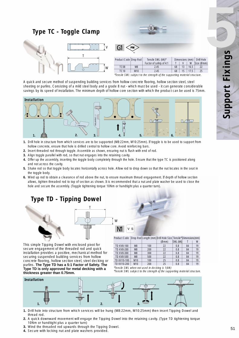
Type TD - Tipping Dowel
51
Supp
ort
Fixi
ngs
5Product Code Drop Rod Tensile SWL (kN)* Dimensions (mm) Drill Hole
Factor of safety of 4:1 T V W Size (Ømm)TC08 M8 2.45 68 13 16.5 22TC10 M10 2.45 68 15 17.5 25
1. Drill hole in structure from which services are to be supported (M8:22mm, M10:25mm). If toggle is to be used to support fromhollow concrete, ensure that hole is drilled central to hollow core. Avoid reinforcing bars.
2. Insert threaded rod through toggle. Assemble as shown, ensuring nut is flush with end of rod.3. Align toggle parallel with rod, so that nut engages into the retaining cavity.4. Offer up the assembly, inserting the toggle body completely through the hole. Ensure that the type TC is positioned along
and not across the cavity.5. Shake rod so that toggle body locates horizontally across hole. Allow rod to drop down so that the nut locates in the seat in
the toggle body.6. Wind up rod to obtain a clearance of rod above the nut, to ensure maximum thread engagement. If depth of hollow section
allows, tighten threaded rod to top of section as shown. It is recommended that a nut and plate washer be used to close the hole and secure the assembly. (Toggle tightening torque 10Nm or handtight plus a quarter turn).
Installation
A quick and secure method of suspending building services from hollow concrete flooring, hollow section steel, steelsheeting or purlins. Consisting of a mild steel body and a grade 8 nut - which must be used - it can generate considerablesavings by its speed of installation. The minimum depth of hollow core section with which the product can be used is 75mm.
Type TC - Toggle Clamp
LIND
AP
TE
R
LINDAPTER
LIND
APTER
LINDAPTER LINDAPTER
LINDAPTER
LIND
AP
TE
R
1. Drill hole into structure from which services will be hung (M8:22mm, M10:25mm) then insert Tipping Dowel and thread rod.
2. A quick downward movement will engage the Tipping Dowel into the retaining cavity. (Type TD tightening torque 10Nm or handtight plus a quarter turn)
3. Wind the threaded rod upwards through the Tipping Dowel. 4. Secure with locking nut and plate washers provided.
Installation
This simple Tipping Dowel with enclosed pivot forsecure engagement of the threaded rod and quickinstallation provides a positive, mechanical method forsecuring suspended building services from hollowconcrete flooring, hollow section steel, steel decking orpurlins. The Type TD has a 5:1 Factor of Safety. TheType TD is only approved for metal decking with athickness greater than 0.75mm.
Product Code Drop Rod Length (mm) Drill Hole Size Tensile* Dimensions(mm)(Ømm) SWL (kN) T W
TD KV8-100 M8 100 22 0.8 84 19TD KV8-200 M8 200 22 0.8 84 19TD KV8-300 M8 300 22 0.8 84 19TD KV8-500 M8 500 22 0.8 84 19TD KV10-100 M10 100 25 0.8 84 19TD KV10-200 M10 200 25 0.8 84 19
G1
N1
V
W
T
T
W
1. 2. 3. 4. 5. 6.
1. 2. 3. 4.
*Tensile SWL when not used in decking is 1(kN)*Tensile SWL subject to the strength of the supporting material structure.
*Tensile SWL subject to the strength of the supporting material structure.
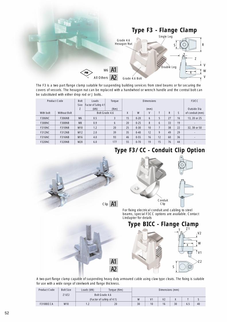
52
*Tensile loads based upon a factor of satey of 4
Type F3 - Flange Clamp
The F3 is a two part flange clamp suitable for suspending building services from steel beams or for securing thecovers of vessels. The hexagon nut can be replaced with a handwheel or wrench handle and the central bolt canbe substituted with either drop rod or J bolts.
Type BICC - Flange Clamp
For fixing electrical conduit and cabling to steelbeams, special F3CC options are available. ContactLindapter for details
Product Code Bolt Loads Torque Dimensions F3/CCSize Factor of Safety 4:1
Z (kN) (Nm) (mm) Outside DiaWith bolt Without Bolt Bolt Grade 4.6 X W V T R S of conduit (mm)
F306NC F306NB M6 0.5 3 15 0-20 6 5 27 16 13, 20 or 25
F308NC F308NB M8 0.9 6 20 0-25 8 6 33 19 -
F310NC F310NB M10 1.2 20 25 0-30 10 7 38 22 32, 38 or 50
F312NC F312NB M12 2.0 39 35 0-40 12 9 49 29 -
F316NC F316NB M16 4.0 93 46 0-55 16 12 60 36 -
F320NC F320NB M20 6.0 177 55 0-70 19 15 76 44 -
Product Code Bolt Size Loads (kN) Torque (Nm) Dimensions (mm)
Z1/Z2 Bolt Grade 4.6
(Factor of safety of 4:1) W V1 V2 X T S
F310BICCA M10 1.2 20 30 10 16 30 6.5 40
A1
A1A2
R
WXV
T
V
Z
S
Type F3/CC - Conduit Clip Option
A two-part flange clamp capable of suspending heavy duty armoured cable using claw type cleats. The fixing is suitablefor use with a wide range of steelwork and flange thickness.
Single Leg
Double Leg
Grade 4.6 Bolt
ConduitClip
Grade 4.6Hexagon Nut
M6
A2All Others
A1Clip
T
WX
V1
Z2
Z1
S
V2
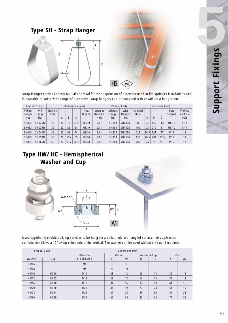
53
Supp
ort
Fixi
ngs
5
Type HW/HC - HemisphericalWasher and Cup
Product Code Dimensions (mm)
Diameter Washer Washer & Cup CupWasher Cup of Bolt/Rod Z X W1 R L Y W2
HW06 - M6 19 9 - - - -
HW08 - M8 22 10 - - - -
HW10 HC10 M10 25 12 13 14 32 12
HW12 HC12 M12 29 12 14 16 35 12
HW16 HC16 M16 34 16 17 19 41 16
HW20 HC20 M20 44 19 22 24 54 19
HW24 HC24 M24 57 25 29 32 67 25
HW30 HC30 M30 67 29 33 35 76 29
Used together to enable building services to be hung via a drilled hole in an angled surface, the cup/washercombination allows a 10° swing either side of the vertical. The washer can be used without the cup, if required.
Strap Hanger carries Factory Mutual approval for the suspension of pipework used in fire sprinkler installations andis available to suit a wide range of pipe sizes, strap hangers can be supplied with or without a hanger nut.
Type SH - Strap Hanger
Product Code Dimensions (mm)
Without With Nominal Nuts WithoutHanger Hanger Bore Tapped Nut/Plain
Nut Nut A B C Hole
SH025 SH025N 25 22 75 57.5 M8/10 9/11
SH032 SH032N 32 22 86 64 M8/10 9/11
SH040 SH040N 40 22 99 74 M8/10 9/11
SH050 SH050N 50 22 116 85 M8/10 9/11
SH065 SH065N 65 22 135 96.5 M8/10 9/11
Product Code Dimensions (mm)
Without With Nominal Nuts WithoutHanger Hanger Bore Tapped Nut/Plain
Nut Nut A B C Hole
SH080 SH080N 80 22 159 114 M8/10 9/11
SH100 SH100N 100 22 219 161 M8/10 9/11
SH125 SH125N 125 26.5 247 177 M12 13
SH150 SH150N 150 26.5 284 199.5 M12 13
SH200 SH200N 200 24 373 261 M16 18
H5
A1
A
B
C
X
W2R
Washer Z
W1 L
Y
Cup
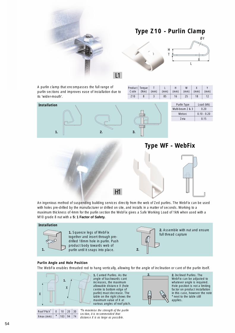
Installation
54
A purlin clamp that encompasses the full range ofpurlin sections and improves ease of installation due toits ‘wider-mouth’.
An ingenious method of suspending building services directly from the web of Zed purlins. The WebFix can be usedwith holes pre-drilled by the manufacturer or drilled on site, and installs in a matter of seconds. Working to amaximum thickness of 4mm for the purlin section the WebFix gives a Safe Working Load of 1kN when used with aM10 grade 8 nut with a 5: 1 Factor of Safety.
Purlin Angle and Hole PositionThe WebFix enables threaded rod to hang vertically, allowing for the angle of inclination or cant of the purlin itself.
2. Inclined Purlins. TheWebFix can be adjusted towhatever angle is required.Hole position is not a limitingfactor on product installationin this case, however the note* next to the table stillapplies.
1. Canted Purlins. As theangle of backwards cantincreases, the maximumallowable distance X (holecentre to bottom edge ofpurlin) must decrease. Thetable on the right shows themaximum value of X atvarious angles of roof pitch.
2. Assemble with nut and ensurefull thread capture1. Squeeze legs of WebFix
together and insert through pre-drilled 18mm hole in purlin. Pushproduct body towards web ofpurlin until it snaps into place.
Type Z10 - Purlin Clamp
Type WF - WebFix
Product Torque T L H W X YCode (Nm) (mm) (mm) (mm) (mm) (mm) (mm)
Z10 8 3 85 16 25 18 12
Purlin Type Load (kN)Multi-beam 2 & 3 0.20
Metsec 0.10 - 0.20
Zeta 0.15
Installation
Roof Pitch˚ 0 10 20 30
Xmax (mm) * 103 94 74
*To maximise the strength of the purlinsection, it is recommended thatdistance X is as large as possible.
L1
H1
ØY
XL
X
X
TH
1. 2. 3.
1. 2.
1.
2.
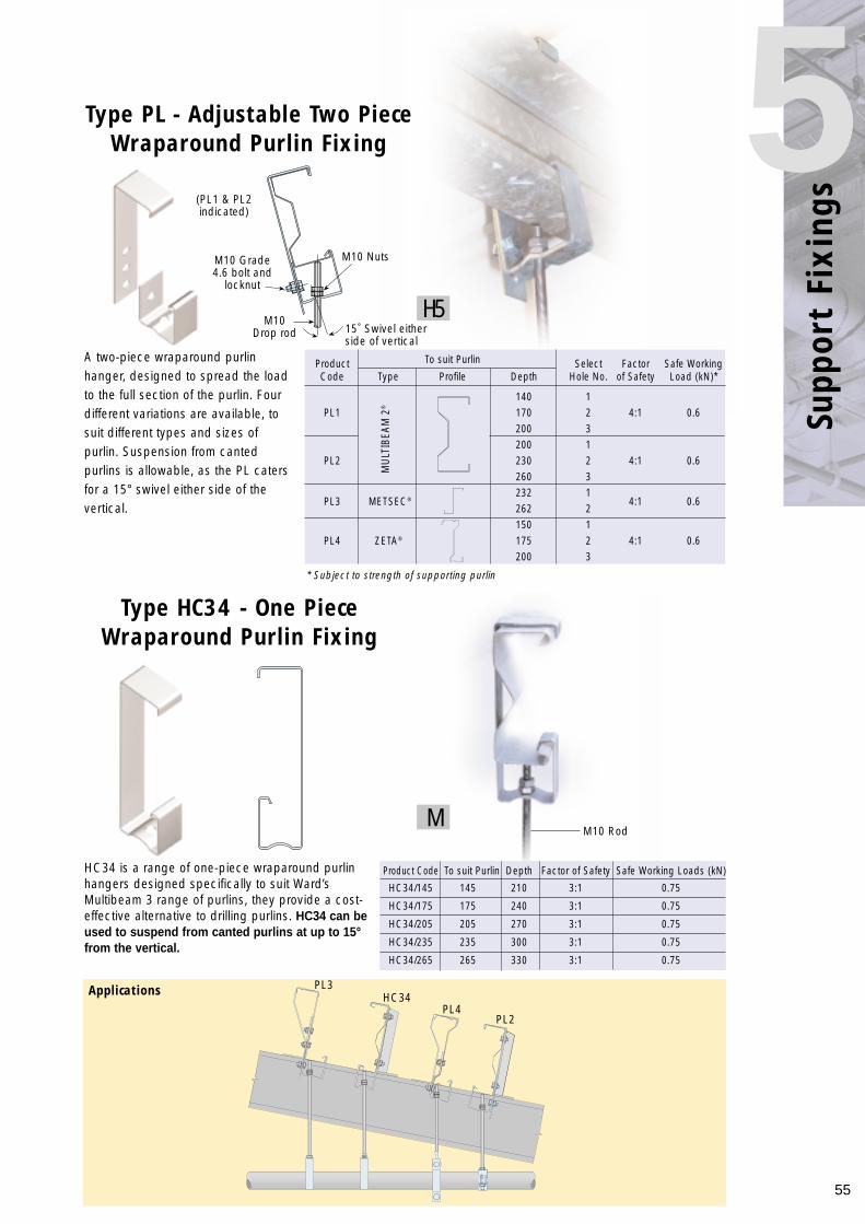
55
Supp
ort
Fixi
ngs
5A two-piece wraparound purlinhanger, designed to spread the loadto the full section of the purlin. Fourdifferent variations are available, tosuit different types and sizes ofpurlin. Suspension from cantedpurlins is allowable, as the PL catersfor a 15° swivel either side of thevertical.
HC34 is a range of one-piece wraparound purlinhangers designed specifically to suit Ward’sMultibeam 3 range of purlins, they provide a cost-effective alternative to drilling purlins. HC34 can beused to suspend from canted purlins at up to 15°from the vertical.
Type PL - Adjustable Two PieceWraparound Purlin Fixing
Type HC34 - One PieceWraparound Purlin Fixing
Product To suit Purlin Select Factor Safe WorkingCode Type Profile Depth Hole No. of Safety Load (kN)*
140 1PL1 170 2 4:1 0.6
200 3200 1
PL2 230 2 4:1 0.6260 3
PL3 METSEC®232 1
4:1 0.6262 2150 1
PL4 ZETA® 175 2 4:1 0.6200 3
MU
LTIB
EAM
2®
Product Code To suit Purlin Depth Factor of Safety Safe Working Loads (kN)
HC34/145 145 210 3:1 0.75
HC34/175 175 240 3:1 0.75
HC34/205 205 270 3:1 0.75
HC34/235 235 300 3:1 0.75
HC34/265 265 330 3:1 0.75
Applications
H5
M
M10 NutsM10 Grade4.6 bolt and
locknut
(PL1 & PL2indicated)
M10 Drop rod
M10 Rod
15˚ Swivel eitherside of vertical
PL3HC34
PL4PL2
* Subject to strength of supporting purlin
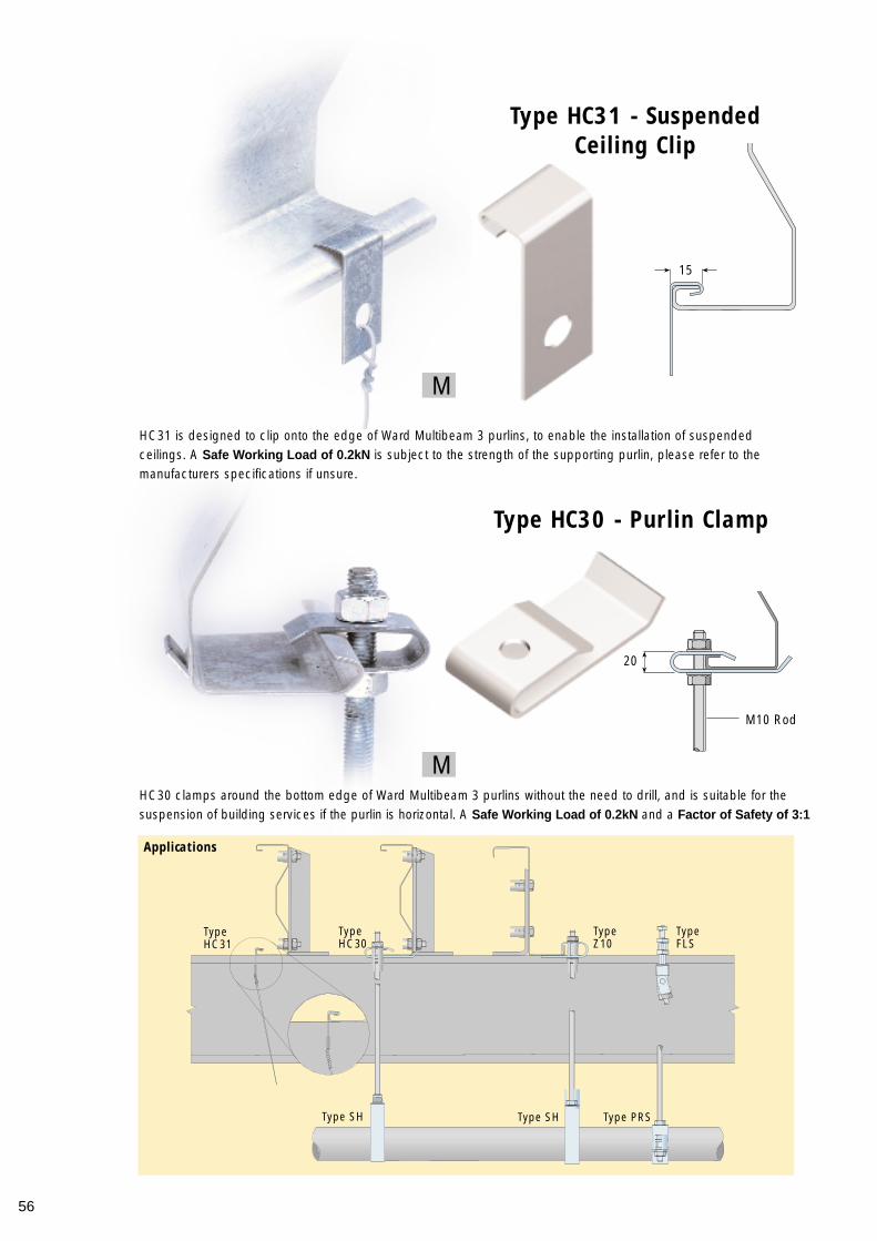
56
HC30 clamps around the bottom edge of Ward Multibeam 3 purlins without the need to drill, and is suitable for thesuspension of building services if the purlin is horizontal. A Safe Working Load of 0.2kN and a Factor of Safety of 3:1
Type HC31 - SuspendedCeiling Clip
HC31 is designed to clip onto the edge of Ward Multibeam 3 purlins, to enable the installation of suspendedceilings. A Safe Working Load of 0.2kN is subject to the strength of the supporting purlin, please refer to themanufacturers specifications if unsure.
Type HC30 - Purlin Clamp
Applications
M
M
15
20
M10 Rod
TypeHC31
TypeHC30
TypeZ10
Type SH Type SH Type PRS
TypeFLS
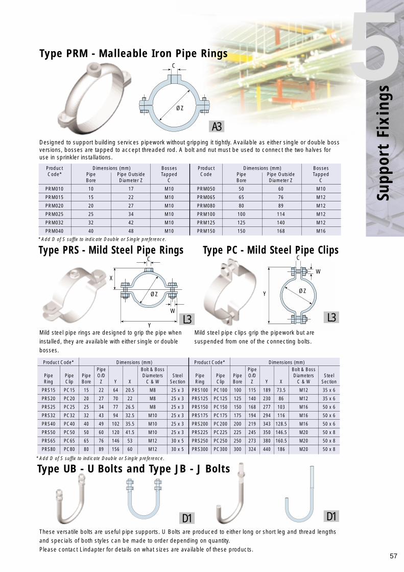
57
Supp
ort
Fixi
ngs
5Designed to support building services pipework without gripping it tightly. Available as either single or double bossversions, bosses are tapped to accept threaded rod. A bolt and nut must be used to connect the two halves foruse in sprinkler installations.
Mild steel pipe rings are designed to grip the pipe wheninstalled, they are available with either single or doublebosses.
Mild steel pipe clips grip the pipework but aresuspended from one of the connecting bolts.
These versatile bolts are useful pipe supports. U Bolts are produced to either long or short leg and thread lengthsand specials of both styles can be made to order depending on quantity.Please contact Lindapter for details on what sizes are available of these products.
Type PRS - Mild Steel Pipe Rings Type PC - Mild Steel Pipe Clips
Product Dimensions (mm) Bosses Product Dimensions (mm) BossesCode* Pipe Pipe Outside Tapped Code Pipe Pipe Outside Tapped
Bore Diameter Z C Bore Diameter Z C
PRM010 10 17 M10 PRM050 50 60 M10
PRM015 15 22 M10 PRM065 65 76 M12
PRM020 20 27 M10 PRM080 80 89 M12
PRM025 25 34 M10 PRM100 100 114 M12
PRM032 32 42 M10 PRM125 125 140 M12
PRM040 40 48 M10 PRM150 150 168 M16
Product Code* Dimensions (mm) Product Code* Dimensions (mm)Pipe Bolt & Boss Pipe Bolt & Boss
Pipe Pipe Pipe O/D Diameters Steel Pipe Pipe Pipe O/D Diameters SteelRing Clip Bore Z Y X C & W Section Ring Clip Bore Z Y X C & W Section
PRS15 PC15 15 22 64 20.5 M8 25 x 3 PRS100 PC100 100 115 189 73.5 M12 35 x 6
PRS20 PC20 20 27 70 22 M8 25 x 3 PRS125 PC125 125 140 230 86 M12 35 x 6
PRS25 PC25 25 34 77 26.5 M8 25 x 3 PRS150 PC150 150 168 277 103 M16 50 x 6
PRS32 PC32 32 43 94 32.5 M10 25 x 3 PRS175 PC175 175 194 294 116 M16 50 x 6
PRS40 PC40 40 49 102 35.5 M10 25 x 3 PRS200 PC200 200 219 343 128.5 M16 50 x 6
PRS50 PC50 50 60 120 41.5 M10 25 x 3 PRS225 PC225 225 245 350 146.5 M20 50 x 8
PRS65 PC65 65 76 146 53 M12 30 x 5 PRS250 PC250 250 273 380 160.5 M20 50 x 8
PRS80 PC80 80 89 156 60 M12 30 x 5 PRS300 PC300 300 324 440 186 M20 50 x 8
A3
L3L3
D1D1
Type PRM - Malleable Iron Pipe Rings
C
C
ØZY
W
C
X
W
ØZ
ØZ
Y
Type UB - U Bolts and Type JB - J Bolts
* Add D of S suffix to indicate Double or Single preference.
* Add D of S suffix to indicate Double or Single preference.
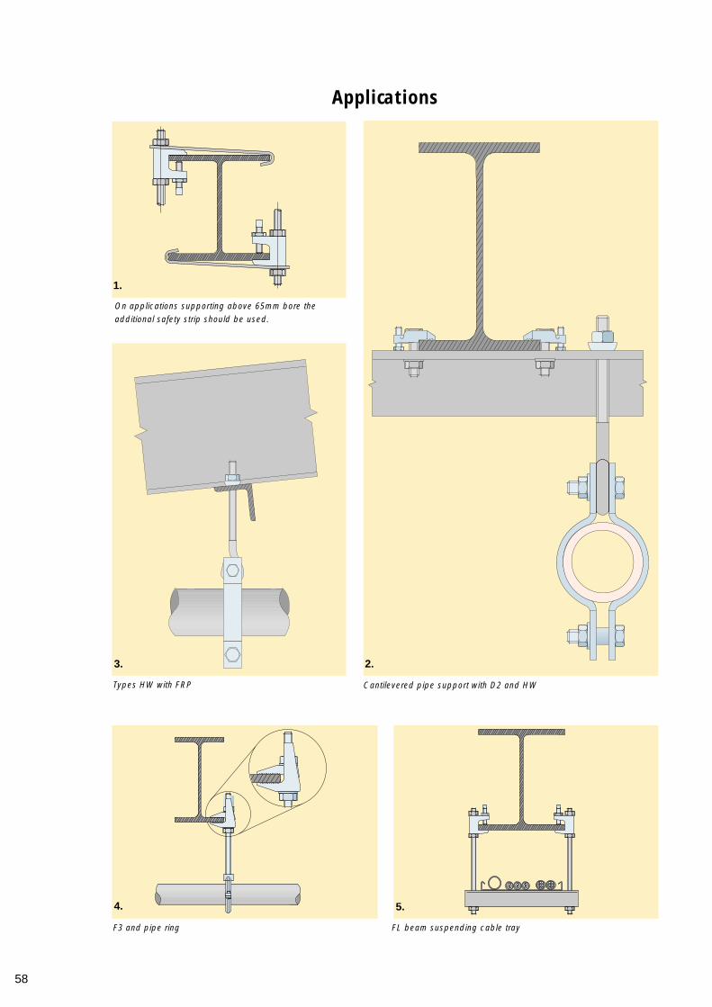
58
Applications
On applications supporting above 65mm bore theadditional safety strip should be used.
Cantilevered pipe support with D2 and HW
F3 and pipe ring FL beam suspending cable tray
Types HW with FRP
1.
2.3.
5.4.
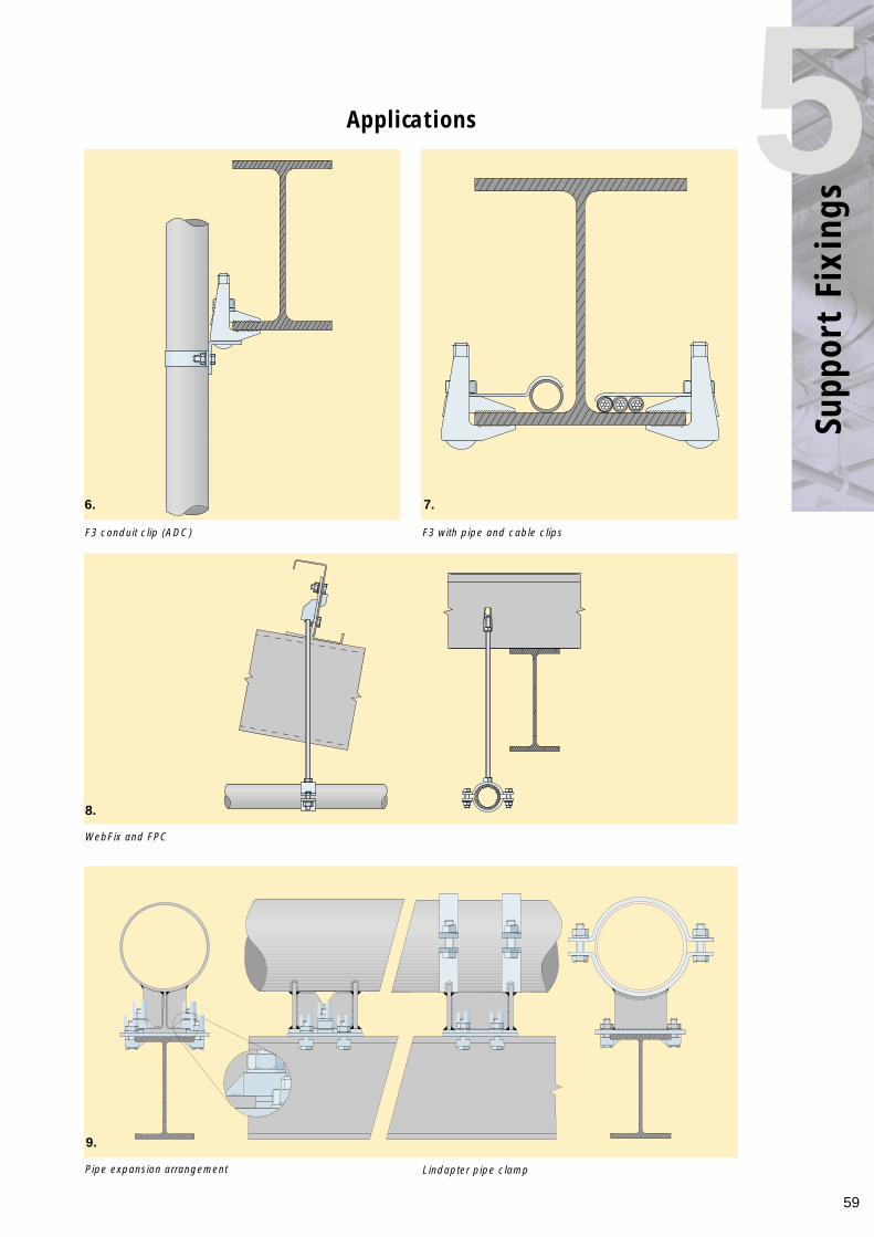
59
Supp
ort
Fixi
ngs
5Applications
F3 conduit clip (ADC)
WebFix and FPC
Pipe expansion arrangement Lindapter pipe clamp
F3 with pipe and cable clips
6.
8.
9.
7.
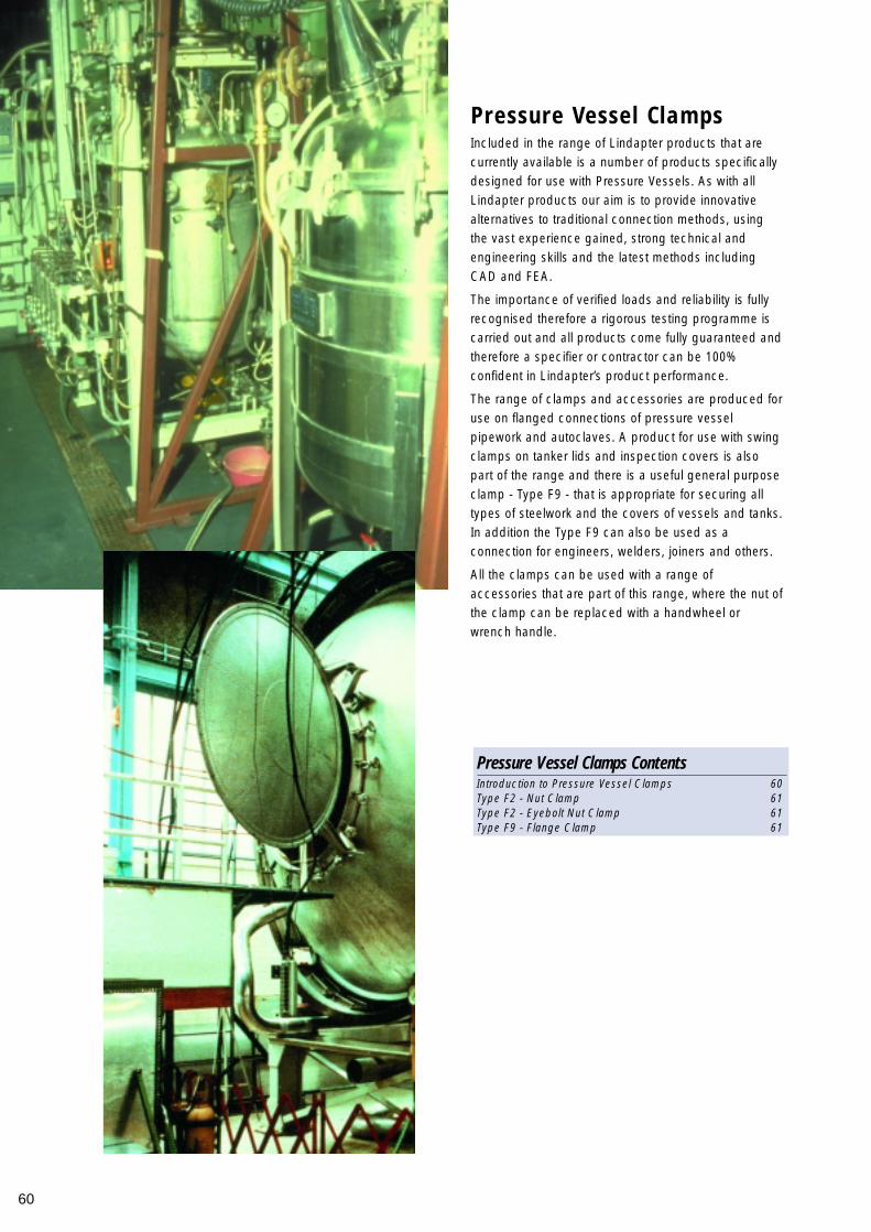
60
Included in the range of Lindapter products that arecurrently available is a number of products specificallydesigned for use with Pressure Vessels. As with allLindapter products our aim is to provide innovativealternatives to traditional connection methods, usingthe vast experience gained, strong technical andengineering skills and the latest methods includingCAD and FEA.
The importance of verified loads and reliability is fullyrecognised therefore a rigorous testing programme iscarried out and all products come fully guaranteed andtherefore a specifier or contractor can be 100%confident in Lindapter’s product performance.
The range of clamps and accessories are produced foruse on flanged connections of pressure vesselpipework and autoclaves. A product for use with swingclamps on tanker lids and inspection covers is alsopart of the range and there is a useful general purposeclamp - Type F9 - that is appropriate for securing alltypes of steelwork and the covers of vessels and tanks.In addition the Type F9 can also be used as aconnection for engineers, welders, joiners and others.
All the clamps can be used with a range ofaccessories that are part of this range, where the nut ofthe clamp can be replaced with a handwheel orwrench handle.
Pressure Vessel Clamps ContentsIntroduction to Pressure Vessel Clamps 60Type F2 - Nut Clamp 61Type F2 - Eyebolt Nut Clamp 61Type F9 - Flange Clamp 61
Pressure Vessel Clamps
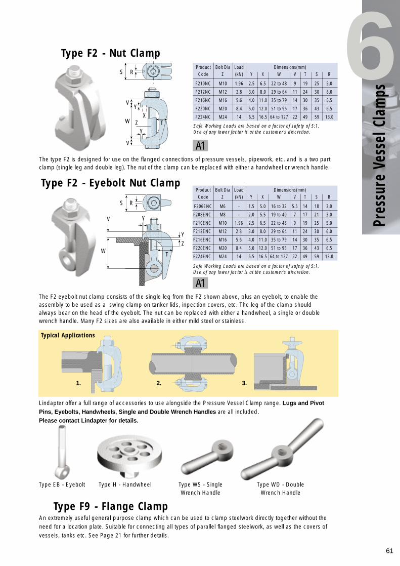
Product Bolt Dia Load Dimensions(mm)Code Z (kN) Y X W V T S R
F210NC M10 1.96 2.5 6.5 22 to 48 9 19 25 5.0
F212NC M12 2.8 3.0 8.0 29 to 64 11 24 30 6.0
F216NC M16 5.6 4.0 11.0 35 to 79 14 30 35 6.5
F220NC M20 8.4 5.0 12.0 51 to 95 17 36 43 6.5
F224NC M24 14 6.5 16.5 64 to 127 22 49 59 13.0
61
Pres
sure
Ves
sel C
lam
ps
6The type F2 is designed for use on the flanged connections of pressure vessels, pipework, etc. and is a two partclamp (single leg and double leg). The nut of the clamp can be replaced with either a handwheel or wrench handle.
An extremely useful general purpose clamp which can be used to clamp steelwork directly together without theneed for a location plate. Suitable for connecting all types of parallel flanged steelwork, as well as the covers ofvessels, tanks etc. See Page 21 for further details.
The F2 eyebolt nut clamp consists of the single leg from the F2 shown above, plus an eyebolt, to enable theassembly to be used as a swing clamp on tanker lids, inpection covers, etc. The leg of the clamp shouldalways bear on the head of the eyebolt. The nut can be replaced with either a handwheel, a single or doublewrench handle. Many F2 sizes are also available in either mild steel or stainless.
Type F2 - Nut Clamp
Type F9 - Flange Clamp
Product Bolt Dia Load Dimensions(mm)Code Z (kN) Y X W V T S R
F206ENC M6 - 1.5 5.0 16 to 32 5.5 14 18 3.0
F208ENC M8 - 2.0 5.5 19 to 40 7 17 21 3.0
F210ENC M10 1.96 2.5 6.5 22 to 48 9 19 25 5.0
F212ENC M12 2.8 3.0 8.0 29 to 64 11 24 30 6.0
F216ENC M16 5.6 4.0 11.0 35 to 79 14 30 35 6.5
F220ENC M20 8.4 5.0 12.0 51 to 95 17 36 43 6.5
F224ENC M24 14 6.5 16.5 64 to 127 22 49 59 13.0
Type F2 - Eyebolt Nut Clamp
Safe Working Loads are based on a factor of safety of 5:1. Use of any lower factor is at the customer's discretion.
Safe Working Loads are based on a factor of safety of 5:1. Use of any lower factor is at the customer's discretion.
Typical Applications
S
W
V
X
V
S
W
V Y
Y
T
Z
R
Y
ZY
T
R
1. 2. 3.
Type EB - Eyebolt Type H - Handwheel Type WS - SingleWrench Handle
Type WD - DoubleWrench Handle
A1
A1
Lindapter offer a full range of accessories to use alongside the Pressure Vessel Clamp range. Lugs and PivotPins, Eyebolts, Handwheels, Single and Double Wrench Handles are all included.Please contact Lindapter for details.
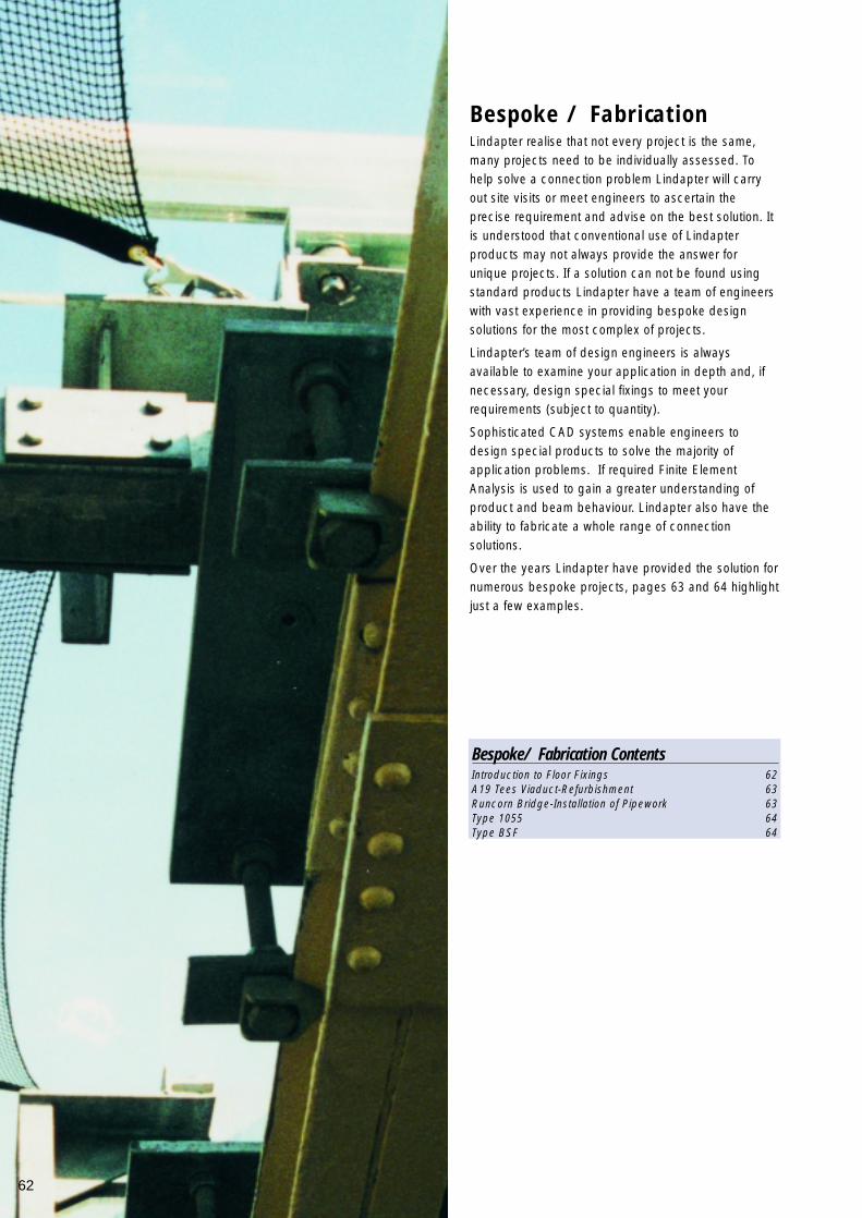
Lindapter realise that not every project is the same,many projects need to be individually assessed. Tohelp solve a connection problem Lindapter will carryout site visits or meet engineers to ascertain theprecise requirement and advise on the best solution. Itis understood that conventional use of Lindapterproducts may not always provide the answer forunique projects. If a solution can not be found usingstandard products Lindapter have a team of engineerswith vast experience in providing bespoke designsolutions for the most complex of projects.
Lindapter’s team of design engineers is alwaysavailable to examine your application in depth and, ifnecessary, design special fixings to meet yourrequirements (subject to quantity).
Sophisticated CAD systems enable engineers todesign special products to solve the majority ofapplication problems. If required Finite ElementAnalysis is used to gain a greater understanding ofproduct and beam behaviour. Lindapter also have theability to fabricate a whole range of connectionsolutions.
Over the years Lindapter have provided the solution fornumerous bespoke projects, pages 63 and 64 highlightjust a few examples.
Bespoke / Fabrication
62
Bespoke/ Fabrication ContentsIntroduction to Floor Fixings 62A19 Tees Viaduct-Refurbishment 63Runcorn Bridge-Installation of Pipework 63Type 1055 64Type BSF 64
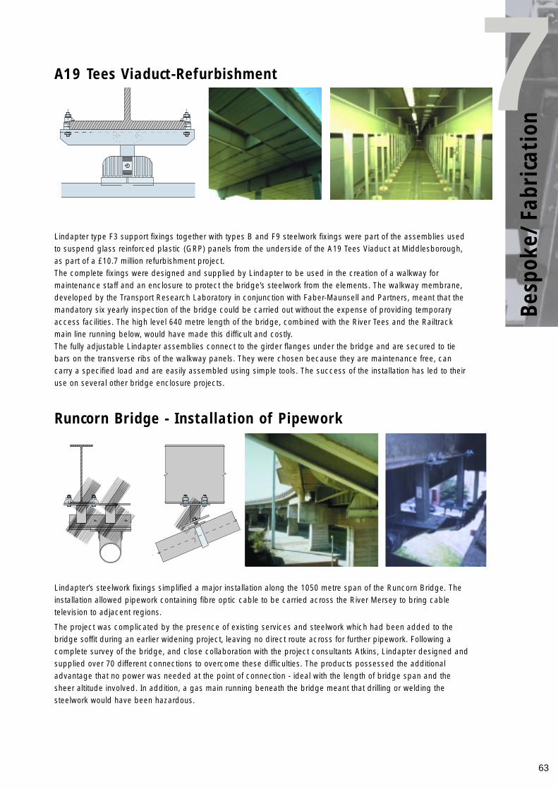
63
Besp
oke/
Fabr
icat
ion7
Lindapter type F3 support fixings together with types B and F9 steelwork fixings were part of the assemblies usedto suspend glass reinforced plastic (GRP) panels from the underside of the A19 Tees Viaduct at Middlesborough,as part of a £10.7 million refurbishment project.The complete fixings were designed and supplied by Lindapter to be used in the creation of a walkway formaintenance staff and an enclosure to protect the bridge’s steelwork from the elements. The walkway membrane,developed by the Transport Research Laboratory in conjunction with Faber-Maunsell and Partners, meant that themandatory six yearly inspection of the bridge could be carried out without the expense of providing temporaryaccess facilities. The high level 640 metre length of the bridge, combined with the River Tees and the Railtrackmain line running below, would have made this difficult and costly.The fully adjustable Lindapter assemblies connect to the girder flanges under the bridge and are secured to tiebars on the transverse ribs of the walkway panels. They were chosen because they are maintenance free, cancarry a specified load and are easily assembled using simple tools. The success of the installation has led to theiruse on several other bridge enclosure projects.
A19 Tees Viaduct-Refurbishment
Runcorn Bridge - Installation of Pipework
Lindapter’s steelwork fixings simplified a major installation along the 1050 metre span of the Runcorn Bridge. Theinstallation allowed pipework containing fibre optic cable to be carried across the River Mersey to bring cabletelevision to adjacent regions.
The project was complicated by the presence of existing services and steelwork which had been added to thebridge soffit during an earlier widening project, leaving no direct route across for further pipework. Following acomplete survey of the bridge, and close collaboration with the project consultants Atkins, Lindapter designed andsupplied over 70 different connections to overcome these difficulties. The products possessed the additionaladvantage that no power was needed at the point of connection - ideal with the length of bridge span and thesheer altitude involved. In addition, a gas main running beneath the bridge meant that drilling or welding thesteelwork would have been hazardous.
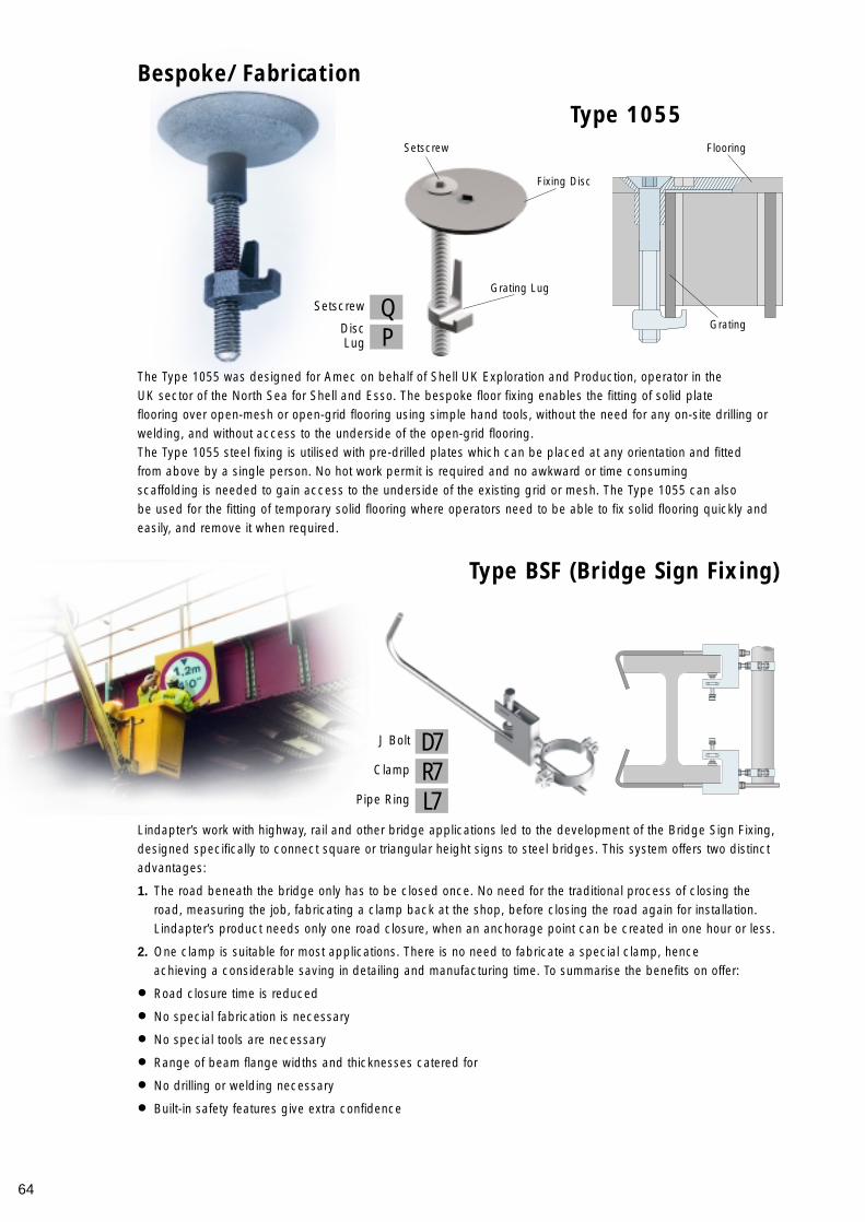
64
The Type 1055 was designed for Amec on behalf of Shell UK Exploration and Production, operator in the UK sector of the North Sea for Shell and Esso. The bespoke floor fixing enables the fitting of solid plate flooring over open-mesh or open-grid flooring using simple hand tools, without the need for any on-site drilling orwelding, and without access to the underside of the open-grid flooring. The Type 1055 steel fixing is utilised with pre-drilled plates which can be placed at any orientation and fitted from above by a single person. No hot work permit is required and no awkward or time consuming scaffolding is needed to gain access to the underside of the existing grid or mesh. The Type 1055 can also be used for the fitting of temporary solid flooring where operators need to be able to fix solid flooring quickly andeasily, and remove it when required.
Lindapter’s work with highway, rail and other bridge applications led to the development of the Bridge Sign Fixing,designed specifically to connect square or triangular height signs to steel bridges. This system offers two distinctadvantages:
1. The road beneath the bridge only has to be closed once. No need for the traditional process of closing the road, measuring the job, fabricating a clamp back at the shop, before closing the road again for installation. Lindapter’s product needs only one road closure, when an anchorage point can be created in one hour or less.
2. One clamp is suitable for most applications. There is no need to fabricate a special clamp, hence achieving a considerable saving in detailing and manufacturing time. To summarise the benefits on offer:
• Road closure time is reduced
• No special fabrication is necessary
• No special tools are necessary
• Range of beam flange widths and thicknesses catered for
• No drilling or welding necessary
• Built-in safety features give extra confidence
Bespoke/Fabrication
Type 1055
Type BSF (Bridge Sign Fixing)
Fixing Disc
Flooring
Grating
Setscrew
Grating Lug
QSetscrew
PDiscLug
D7J Bolt
R7Clamp
L7Pipe Ring
65
Lindapter has operated a Product Development department comprising of both qualifiedengineers and technician apprentices for over twenty-five years.
The Product Development strategy encompasses:Providing high quality technically innovative fixing solutions to the construction industry. Continually improving best practice on-site.Design to strengthen and carry the Lindapter brand across all sales territories.The responsibility of the department includes the introduction of additional core products to therange, continuous research and product testing, forming design and research partnershipsand also the management of Trade Marks and Patents.
The design partnerships already established include:
CorusThe Steel Construction Institute (SCI) The British Constructional Steelwork Association (BCSA)CIDECT. (Comité International pour le Développement et l’ Etude de la Construction Tubulaire)Building Research Establishment (BRE)American Institute of Steel Construction (AISC)Consultant Design Engineering Companies
Research Partnerships which Lindapter have already been involved with include:
Leeds UniversitySheffield UniversityNottingham UniversityOxford UniversityTrento UniversityHERA New Zealand Heavy Engineering Research AssociationUniversity of TorontoTechnische Universität Hamburg-HarburgUniversity of ManchesterOxford BrookesUniversität Karlsruhe (TH)
Product Development within Lindapter has many services it can provide you, the customer:
Product Design / DevelopmentProduct Testing / EvaluationCAD Facility 2D / 3DFinite Element AnalysisProduction Drawing ManagementReport GenerationPatent & Trade Mark ManagementTechnical Assistance
The facility utilises the latest computer aided design systems combined with three separatetest machines. One 2 ton, 5 ton and 100 ton respectively. With computerised data logging,curve mapping and Finite Element systems, real time application analysis can be provided toour customers on a daily basis if required.
Potential customers are regularly invited to the facility to witness Lindapter connection productssubjected to applied load tests. And actual product demonstrations are often critical insecuring projct based business.
In the opinion of Lindapter there are no such connections as non-critical connections - allconnection devices are required to meet known applied loads which should give peace ofmind to specifiers and contractors alike.
For any applications beyond the scope of the standard Lindapter product range, the ProductDevelopment Team will be happy to work alongside your organisation to engineer alternativebespoke solutions based upon suitable product volume.
Product Development

Quality
Testing and Approvals
66
Lindapter believes in gaining the full support of industry approval bodies wherever relevant to our products. As youlook at the products in the Lindapter catalogue, the following symbols are placed alongside products which areapproved by the particular body.
The Lindapter product range offers you a flexible, reliable and cost effective alternative to the more traditionalmethods of securing steelwork, such as site drilling or welding. The range provides the most demanding engineerswith an effective solution to their fixing requirements under the most arduous conditions and in sometimeshazardous and corrosive environments worldwide. Lindapter International continually strives to improve, in order tomaintain the ultimate in quality standards for its products and services. This means that whether you are a specifieror a user you can be 100% confident in Lindapter’s product performance.In accordance with this policy, Lindapter is accredited under two quality schemes:
British Standards InstitutionLindapter is registered under BS EN ISO 9001, as a company with a suitable system of quality management.
A copy of Lindapter’s quality policy is available on request.
Structural ApprovalsThe Deutsche Institut für Bautechnik, Berlin is a body which approves products and materials for use in structural engineering applications in the construction and civil engineering industries.
Lloyds Register Type Approved Products have been subjected to tensile, frictional, shear, vibration and shock tests, witnessed and verified by Lloyds Register.
The TUV approval is the certifying authority for safety, qualityand environmental protection
Det Norske Veritas has approved the use of Lindapter products in lifting applications. This includes their use on both mobile and fixed offshore installations.
Fire Protection ApprovalsThe American Insurance Association, Factory Mutual, offers an approval which is recognised by the fire protection industry world-wide.
Verband der Schadenversicherer e.v. is a German insuranceassociation who also offer a rigorous approval for products used in the fire protection industry.
These approvals serve to reinforce Lindapter’s extensive in-house testing procedures. All Lindapter products arefully tested in all relevant applications, so you can be 100% confident whether specifying or using that Lindapterproducts will perform as per the information detailed in this catalogue. Loads published are the product safeworking loads, taking into account a guaranteed factor of safety (5 or 4 in most cases).
BS EN ISO 9001:1994 Q5143

67

Lindapter InternationalLindsay House
Brackenbeck RoadBradford
West YorkshireBD7 2NFEngland
Tel: +44 (0) 1274 521444Fax: +44 (0) 1274 521130
Email: [email protected]
www.lindapter.com
Your Lindapter Distributor is:
BS EN ISO 9001:1994 Q5143