line of manifolds - ham-letham-let.com/images/fittings/hamlet/cms/products/new_products/ham... · 2...
TRANSCRIPT

Line of Manifolds
TH
E
ST
OP
PI
NG
P
OW
ER
235WAY MANIFOLD

2With its wide variety of solutions, choice of materials, options for standard packing, and range of valve configurations and flow schemes, Ham-let ASTAVA line of manifolds will meet your needs. The comprehensive and simple “HOW TO ORDER” table will guide you to the best configuration for your application.
The Ham-Let ASTAVA line provides a total solution with a full range of instrument hook-ups including protection housings, heating, and junction boxes, all complying with international standards.
All 316 stainless steel construction with packing or O-ring concept. Other material options are available as standard. NACE MR-01-075 as standard. Working pressures up to 10,000 psig. Temperatures up to 550°C (1022°F) with Grafoil® packing.
INTRODUCTION
The Ham-Let Astava Line of Instrument Manifolds consists of a full range of 2, 3 and 5-way instrument manifolds, which are fully compatible with the requirements of the Oil, Gas and Petro-chemical industries, and meet the requirements of most pressure, differential level and flow applications.
INDEX Introduction 02
Manifold features and benefit 03
Bonnet and stem concept 04
Material of construction 05
2 Way Direct mount concept 06
2 Way Direct mount dimensions 07
2 Way Remote mount concept 08
2 Way Remote mount dimensions 09
Ordering information for 2-Way 10
3 Way Direct mount dimensions 11
3 Way Remote mount dimensions 13
Ordering information for 3-Way 14
5 Way Direct mount dimensions 15
5 Way Remote mount dimensions 17
Ordering information for 5-Way 18

3
TE
CH
NIC
AL D
ATA
MANIFOLD FEATURES AND BENEFITS
Blowout-proof stem Safety back seat stem-tip for a secondary seal in the fully opened position Safety stop pin – prevents the bonnet from detaching the body due to vibration Stem seals below stem threads - isolate the stem threads from system fluid Optional Grafoil® packing for high temperature service A choice of O-ring materials Oxygen cleaned manifolds, per ASTM G-93 – optional Full traceability of all construction materials 100% Factory Tested Compliance with MSS–SP-99 Direct mount flange design per IEC61518
The following unique features of the Ham-Let Astava Line of Instrument Manifolds enable tailoring our high-quality products to the exact requirement of the customer and application:
NACE MR-01-75
All Manifolds comply to NACE MR-01-75 as standard.
FULL TRACEABILITY
All products are fully traceable to its components.
CERAMIC STEM BALL TIP
Superior hardness prevents deformation of the sealing tip and wear, significantly increasing the life time of the product for isolation purposes.
BONNET SELECTIONS
O-ring stem-seal bonnet1. No packing adjustment 2. Extremely low operating torque 3. Compact design 4. Long life cycle 5. Sealing below stem thread
Packing stem-seal bonnet1. wide chemical compatibility range 2. High temperature option (Grafoil®) 3. Low operating torque 4. Sealing below stem thread
WIDE VARIETY OF SEALING MATERIALS
PTFE; Grafoil®; Viton®; NBR; EPDM; Silicon; perfluorelastomer – provides wide coverage of applications.
STEM MATERIAL
ST. ST. 316 TI with chromium carbide diffusion coating1. Long life cycle 2. Prevent galling
Features

4The special sealing design applied in all Ham-Let Astava Instrument Manifolds features a non-rotating ceramic ball tip.
The chemical composition of a ceramic ball tip is superior in hardness and functionality to a metal ball tip, eliminating sealing tip deformation and significantly increasing the life of the product.
The stem threads are rolled and an integrated back seat design is applied to the packing type of bonnet. Applying a Stainless Steel 316 Ti stem with a chromium carbide diffusion coating results in maximum operation cycles and minimal risk of stem galling. Both packing and O-ring bonnets are designed with sealing below stem threads for maximum protection of the stem threads. For maximum safety, the bonnet design prevents stem blowout, and a locking pin prevents unintentional disassembling of bonnet.
BONNET AND STEM CONCEPT
For severe-service applications, Ham-Let Astava Manifolds can be configured with a metal-to-metal seal below the bonnet thread, a dust-ring attached to the bonnet thread or tack-weld on the locking pin for extreme vibrating conditions.
Red: Vent Valves
Blue: Isolate Valves
Green: Equalize Valves
PRESSURE AND TEMPERATURE RATING
The valve bonnets have color coded ring labels for service identification:
Grafoil® Down to -200°C (-364°F)
PTFE Down to -160°C (-256°F)
Viton® Down to -20°C (-4°F)
NBR Down to -34°C (-29°F)
Perfluor Down to -40°C (-40°F)
EPDM Down to -45°C (-364°F)®
10,000 psi (690 bar) Available upon request
Handle OptionsThe standard handle of the Ham-Let Astava Line of Instrument Manifolds is a stainless steel T-bar. For high pressure applications of 10,000 psi (690 bar) an extended T-bar or hand wheel can be applied. Anti-tamper bonnet and key lock options assure that the manifold is operated by qualified personnel only.
TestingAll Ham-let instrument manifolds are factory tested with Nitrogen at 800 psig (55 bar) based on MSS-99. Seats have a maximum allowable leak rate of 0.1 std cm3 /min. Hydrostatic and Helium leak test is available upon request.
Cleaning All Ham-let instrument manifolds are cleaned in accordance with ASTAVA cleaning procedure WIQ-016 Oxygen clean is available in accordance with ASTM G-93.
Packing Material
O-Ring Material
690
600
500
400
300
200
100
0 0
1000
2000
3000
4000
5000
6000
7000
8000
9000
10000
0
0 130 230 330 430 530 630 730 830 932 1030 1130 1230
100 200 300 400 500 600 700
Temperature (°C)
Temperature (°F)
Pres
sure
(bar
)
Pres
sure
(Psi
g)
T-bar
Anti-tamper
Hand wheel

Packing Bonnet O-ring Bonnet Metal-to-Metal Bonnet
No Part Qty. Material Qty. Material Qty. Material1 Set Screw 1 St.St. 304 1 St.St. 304 1 St.St. 304
2 Bar Handle 1 St.St. 316L 1 St.St. 316L 1 St.St. 316L
3 Gland 1 St.St. 316L - - - -
4 Locking Nut 1 St.St. 316L - - - -
5A Pressure ring 1 St.St. 316L - - - -
5B Back-up ring - - 2 Virgin PTFE 2 Virgin PTFE
6A Stem Packing 1 Virgin PTFE - - - -
6B Stem O-ring - - 1 Viton® (Fluorocarbon FKM) 1 Viton® (Fluorocarbon FKM)
7 Bonnet 1 St.St. 316L 1 St.St. 316L 1 St.St. 316L
8 Stem 1 St.St. 316Ti Chrome-Carbide diffusion coated
1 St.St. 316Ti Chrome-Carbide diffusion coated
1 St.St. 316Ti Chrome-Carbide diffusion coated
9 Ball 1 Ceramic (AL2-O3) 1 Ceramic (AL2-O3) 1 Ceramic (AL2-O3)
10 Dust Protector - - - - 1 Viton® (Fluorocarbon FKM)
Packing Bonnet
O-ring Bonnet
Metal-to-Metal BonnetBottom metal seal protects bonnet’s threads from the fluid.
5
TE
CH
NIC
AL D
ATA
MATERIAL OF CONSTRUCTION
1
2
3
4
5A
6A
7
8
9
1
2
7
10
8
5B
9
6B
1
2
5B6B
9
7
8

62 Way Direct Mount Design
The direct mount 2 way manifold can accommodate a range of products directly connected to a measuring device by a flanged connection.
The flanged connection is based on IEC61518 with ASTM A193 Grade B8 AISI 304 strain hardened bolt class 2 to cover the complete Pressure/Temperature rating. The direct mount concept reduces the number of threaded connections and potential leak points between the process and measuring device.
The direct mount concept also includes a close coupled design with process and instrument flanged connection. 2 way manifolds apply for static pressure measurement by connection to a pressure gauge or transmitter.
2 WAY DIRECT MOUNT CONCEPT
INTERNAL FINISH
Burr-free internal surfaces and threads reduces potential leaks and improves instruments accuracy.
BONNET DESIGN
O-ring / Packing Seal
CONNECTION
Direct mount flange design per IEC61518.
54mm (2 1/8”) port center lines flange connection.
PTFE flange seals as standard.
CONSTRUCTION MATERIALS
Compliance with NACE MR – 01-75. Full traceability of all construction materials.
LOCKING PIN
Prevents accidental detachment of the bonnet from the body in service.
BODY DESIGN
Compact one piece design.High strength.
IEC 61518 is the common standard for connecting a flanged transmitter to a flanged manifold. The transmitter side is standard form A, with the fixed centre-to-centre connection being 54 mm, bolt distance of 41.3, and 7/16 UNF bolting. For Rosemount 3051(S) CD series with integral design, centre-to-centre distance is 33 mm, where the bolting is at 41.3 mm. Contact [email protected] for more details.
7
2 W
AY
MA
NIF
OLD
LIN
E
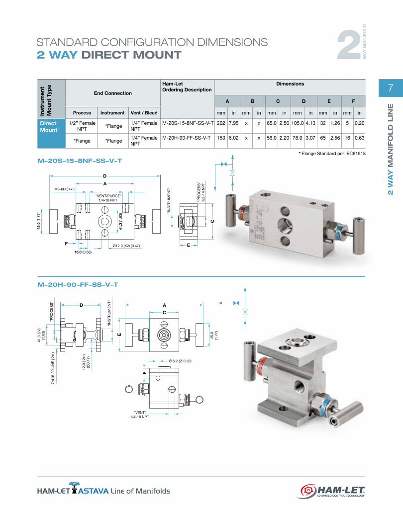
STANDARD CONFIGURATION DIMENSIONS 2 WAY DIRECT MOUNT
Inst
rum
ent
Mo
unt
Typ
e
End Connection
Ham-Let Ordering Description
Dimensions
A B C D E F
Process Instrument Vent / Bleed mm in mm in mm in mm in mm in mm in
Direct Mount
1/2” Female NPT
*Flange1/4” Female NPT
M-20S-15-8NF-SS-V-T 202 7.95 x x 65.0 2.56 105.0 4.13 32 1.26 5 0.20
*Flange *Flange1/4” Female NPT
M-20H-90-FF-SS-V-T 153 6.02 x x 56.0 2.20 78.0 3.07 65 2.56 16 0.63
ISO
LA
TE
PU
RG
E
"P
RO
CE
SS
"1/
2-14
NP
T
"IN
STR
UM
EN
T"
"VENT/PURGE"1/4-18 NPT
M8-6H ( 4x )
41,3
(1.6
3)
16,0 (0.63)
45,
0 (1
.77)
Ø12.0 (X2) (0.47)
D
A
C
EF
ISOLATE
VENT
D A
E
F
C
"P
RO
CE
SS
"
"IN
STR
UM
EN
T"
41,3
(2x)
(1.6
3)
7/4
16-2
0 U
NF
( 2x
)
12,0
( 2x
)(Ø
0.47
)
"VENT"1/4-18 NPT
45,0
(1.7
7)
Ø 8.2 (Ø 0.32)
M-20H-90-FF-SS-V-T
M-20S-15-8NF-SS-V-T* Flange Standard per IEC61518
2 WA
Y M
AN
IFO
LD

82 WAY REMOTE MOUNT DESIGN
The remote concept of the two-valve manifolds’ series combines valves into one block to perform isolation, bleed and calibration of pressure transmitters, gauges and switches. Mainly used in static pressure. Process and instrument ports can be provided in a variety of sizes and threads NPT, BSPT and BSPP.
Ham-Let ASTAVA line of manifolds provides also integral female Let-Lok, male and female connections type as standard.
2 WAY REMOTE MOUNT CONCEPT
LOCKING STOP PIN
Prevents accidental detachment of the bonnet from the body in service.
BODY DESIGN
Compact one piece design. High strength.
INSTRUMENT MOUNTING
Remote mount design with female NPT and Let-Lok end connections.
INTERNAL FINISH
Burr-free internal surfaces and threads. Reduces potential leaks and improves instruments’ accuracy.
CONSTRUCTION MATERIALS
Compliance with NACE MR – 01-75. Full traceability of all construction materials.
BONNET DESIGN
O-ring / Packing Seal

9
2 W
AY
MA
NIF
OLD
LIN
E
"V
EN
T"1/
4-18
NP
T
"PROCESS"1/2-14 NPT
32,0(1.26)
"IN
STR
UM
EN
T"1/
2-14
NP
T
M8-
6H (
2x )
D
VENT
ISO
LA
TE
BE
F
C
A
45.0 (1.77)
Inst
rum
ent
Mo
unt
Typ
e
End Connection
Ham-Let Ordering Description
Dimensions
A B C D E F
Process Instrument Vent / Bleed mm in mm in mm in mm in mm in mm in
Remote Mount
1/2” Female NPT 1/2” Female NPT 1/4” female NPT M-20M-10-8N-SS-V-T 79 3.11 79.0 3.11 32.0 1.26 92.0 3.62 32 1.26 20 0.79
1/2” Female NPT 1/2” Female NPT 1/4” female NPT M-21A-10-8N-SS-V-T 107 4.21 79.4 3.13 65.0 2.56 65.0 2.56 32 1.26 x x
1/2” Female NPT 1/2” Female NPT 1/4” female NPT M-21S-10-8N-SS-V-T 156 6.14 - - 65.0 2.56 59.0 2.32 32 1.26 18 0.71
D
20,0
(0.7
9)
AE
CB
45.0(1.77)
VENT
"VENT"1/4-18 NPT
"IN
STR
UM
EN
T"1/
2-14
NP
T
"P
RO
CE
SS
"1/
2-14
NP
T
M8-6H ( 2x )
F
ISOLATE
M-20M-10-8N-SS-V-T
M-21A-10-8N-SS-V-T
M-21S-10-8N-SS-V-T
ISOLATEV
ENT
A
D
E
E
E
32.0 (1.26)
"PROCESS" 1/2-14 NPT "VENT" 1/4-18 NPT
"INSTRUMENT"1/2-14 NPT
45,0
(1.7
7)
M8-6H ( 2x )
STANDARD CONFIGURATION DIMENSIONS 2 WAY REMOTE MOUNT 2 W
AY
MA
NIF
OLD

10
Ordering information for 2-Way Manifolds:
Option
OC Oxygen Clean
LF LubricantFree
K 10,000 psi (690 bar)
V Vent port1/2”
ValvesPosition
A Angle Flat
S Straight
M Angle Square
H H- Type
Family
M-2 2 Way Manifold
Flow Scheme
0(See
table A)1
End Connection
00 Femaleintegral Let-Lok
10 Female to Female
80 Male to Male
85 Male to Female
15 Female to Flange
90 Flange to Flange
Size
8 1/2”
4 1/4”
6 3/8”
Type End Connection
FF Flange*
N NPT
G BSPP
R BSPT
NF NPT to Flange*
RF BSPT to Flange*
GF BSPP to Flange*
L Female integral Let-Lok
Body Material
SS SS 316
M Monel 400
D Duplex 1.4462
HC Alloy C-276
T Titanium
A8 Alloy 825
A6 Alloy 625
SD SuperDuplex
M-2 1 A 10 8 N SS
Packing
T PTFE
G Grafoil®
V Viton®
EP EPDM
BU NBR
KL Kalrez®
Handle
T T bar
AT Anti Tamper
LD Locking device
T OCLD
(See table A)
Designator Flow Schematic
ValvesPosition Sketch
0
M
H
S
1
S
A
Table A: Flow Schematic and Valve Position
Warning! For your safety The system designer and user have the sole responsibility for selecting products suitable for their special application requirements, ensuring their safe and trouble-free installation, operation, and maintenance. Application details, material compatibility and product ratings should all be considered for each selected product. Improper selection, installation or use of products can cause property damage or personal injury.
* Flange Standard per IEC61518

11
3 W
AY
MA
NIF
OLD
LIN
E
STANDARD CONFIGURATION DIMENSIONS 3 WAY DIRECT MOUNT
M-30H-15-8NF-SS-V-T
M-30I-15-8NF-SS-V-T
41.3
(2X
) (1.
63)
12.0 (X4) 0.47
8.2 (0.32)
54.0 (2X)2.13
EQUALIZE
ISOLATE
ISOLATE
ISOLATE
ISOLATE
D
CA
F
B
E
"P
RO
CE
SS
"(2x
) 1/
2-14
NP
T
45.0 (1.77)
"INSTRUMENT"
EQUALIZ
E
B
C
E
E
E
F
45,0 (1.77)
12.0 (x4) (0.47)
32,0 (1.26)
M8-6H (2x)
41,3
(1.6
3)
"IN
STR
UM
EN
T"
"P
RO
CE
SS
" (2
x)1/
2-14
NP
T
54,0 (2.13)
120,0 (4.72)
Inst
rum
ent
Mo
unt
Typ
e
End Connection
Ham-Let Ordering Description
Dimensions
A B C D E F
Process Instrument Vent / Bleed mm in mm in mm in mm in mm in mm in
Directmount
1/2” Female NPT *Flange - M-30H-15-8NF-SS-V-T 181.0 7.13 95.0 3.74 86.0 3.39 79.0 3.11 66.0 2.60 - -
1/2” Female NPT *Flange - M-30I-15-8NF-SS-V-T 165.0 6.50 106.0 4.17 65.0 2.56 154.0 6.06 32.0 1.26 16.0 0.63
* Flange Standard per IEC61518
3 WA
Y M
AN
IFO
LD

12
M-30A-15-8NF-SS-V-T
"INSTRUMENT"
"P
RO
CE
SS
" ( 2
x )
1/2-
14 N
PT
41,3
(2x)
(1.6
3)
32.0 (1.26)
54.0 (2.13)
M8-6H (2x)
45.
0 (1
.77)
12.0 (4X) 0.47EQU
ALIZE
ISOLATE
BC
DA
EF
ISOLATE
Inst
rum
ent
Mo
unt
Typ
e
End Connection
Ham-Let Ordering Description
Dimensions
A B C D E F
Process Instrument Vent / Bleed mm in mm in mm in mm in mm in mm in
Directmount
1/2” Female NPT *Flange - M-30A-15-8NF-SS-V-T 210.0 8.27 106.0 4.17 65.0 2.56 115.0 4.53 32.0 1.26 16.0 0.63
*Flange *Flange - M-30H-90-FF-SS-V-T 181.0 7.13 95.0 3.74 86.0 3.39 79.0 3.11 66.0 2.60 - -
STANDARD CONFIGURATION DIMENSIONS 3 WAY DIRECT MOUNT
* Flange Standard per IEC61518
EQUALIZE
54
45 (1.77)
41.3
(x2)
(1.6
3)
7/16-20 UNF-2B (4x)
A
D
B
C
E
C
M-30H-90-FF-SS-V-T
3 WA
Y M
AN
IFO
LD

13
3 W
AY
MA
NIF
OLD
LIN
E
STANDARD CONFIGURATION DIMENSIONS 3 WAY REMOTE MOUNT
M-32M-85-8N-SS-V-T
M30S-10-8N-SS-V-T
C
EQ
UA
LIZ
E
ISO
LA
TE
ISO
LA
TE
A D
45,0
(1.7
7)
"PROCESS"(2x)1/4-14 NPT
54,0 (2.13)
"INSTRUMENT"(2x)1/4-14 NPT
54,0 (2.13)
F
n12,0 (0.47)
E
B
B
A
D
"P
RO
CE
SS
"1/
2-14
NP
T
"IN
STR
UM
EN
T"1/
2-14
NP
T
"VENT"1/4-18 NPT
45,0(1.77)
C
33,0(1.30)
E
ISOLATE
ISOLATE
VENT
Inst
rum
ent
Mo
unt
Typ
e
End Connection
Ham-Let Ordering Description
Dimensions
A B C D E F
Process Instrument Vent / Bleed mm in mm in mm in mm in mm in mm in
Remotemount
1/2” Female NPT1/2” Female NPT - M30S-10-8N-SS-V-T 185.0 7.28 79.0 3.11 65.0 2.56 90.0 3.54 32.0 1.26 - -
1/2” Female NPT 1/2”Female NPT 1/4” Female NPT M32M-85-8N-SS-V-T 135.0 5.31 87.0 3.43 40.0 1.57 112.0 4.41 40.0 1.57 - -
3 WA
Y M
AN
IFO
LD

14
Ordering information for 3-Way Manifolds:
ValvesPosition
A Angle Flat
S Straight
M Angle Square
H H- Type
I In - line
Family
M-3 3 Way Manifold
Flow Scheme
0
(See table A)1
2
End Connection
00 Femaleintegral Let-Lok
10 Female to Female
80 Male to Male
85 Male to Female
15 Female to Flange
90 Flange to Flange
Size
8 1/2”
4 1/4”
6 3/8”
Type End Connection
FF Flange*
N NPT
G BSPP
R BSPT
NF NPT to Flange*
RF BSPT to Flange*
GF BSPP to Flange*
L Female integral Let-Lok
Body Material
SS SS 316
M Monel 400
D Duplex 1.4462
HC Alloy C-276
T Titanium
A8 Alloy 825
A6 Alloy 625
SD SuperDuplex
M-3 1 A 10 8 N SS
Packing
T PTFE
G Grafoil®
V Viton®
EP EPDM
BU NBR
KL Kalrez®
Handle
T T bar
AT Anti Tamper
LD Locking device
T OCLD
(See table A)
Designator Flow Schematic
ValvesPosition Sketch
0
S
H
I
A
1 I
2 M
Table A: Flow Schematic and Valve Position
Warning! For your safety The system designer and user have the sole responsibility for selecting products suitable for their special application requirements, ensuring their safe and trouble-free installation, operation, and maintenance. Application details, material compatibility and product ratings should all be considered for each selected product. Improper selection, installation or use of products can cause property damage or personal injury.
* Flange Standard per IEC61518
Option
OC Oxygen Clean
LF LubricantFree
K 10,000 psi (690 bar)
V Vent port1/2”

15
5 W
AY
MA
NIF
OLD
LIN
E
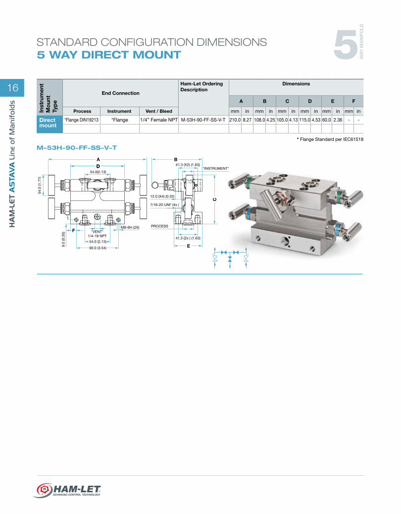
STANDARD CONFIGURATION DIMENSIONS 5 WAY DIRECT MOUNT
M-50A-15-8NF-SS-V-T
B
BE
M8-6H (2x)
"IN
STR
UM
EN
T"
VENT
VENT
D
C
A
PROCESS (2x) 1/2-14NPT
VENT (2x) 1/4-18 NPT
32.0(1.26)
54.0 (2.13)
45.0 (1.77)
45.0 (1.77)
41.3
(1.6
3)
54.0 (2.13)
65.0
(2.5
6)
54.0 (2.13)
ISOLATEISOLATE
EQUALIZE
* Flange Standard per DIN19213 / IEC61518
M-53T-15-8NF-SS-V-T
ISOLATE
VENT
A
A
F
C
B
E
54.0 (2.13)
32.0 (1.26)M8-6H (x2)
41.3
(1.6
3)
54.0 (2.13)
45.0
(1.7
7)
100.
0 (3
.94)
12.0 (x4) (0.47)
INS
TRU
ME
NT
"TEST"( 2x )1/4-18 NPT
PROCESS (2x)1/2-14 NPT VENT
1/4-18 NPT
EQUALIZ
EQUALIZ
Inst
rum
ent
Mo
unt
Typ
e
End Connection
Ham-Let Ordering Description
Dimensions
A B C D E F
Process Instrument Vent / Bleed mm in mm in mm in mm in mm in mm in
Directmount
1/2” Female NPT *Flange 1/4” Female NPT M-50A-15-8NF-SS-V-T 265.0 10.43 41.0 1.61 106.0 4.17 170.0 6.69 32.0 1.26 16.0 0.63
1/2” Female NPT *Flange 1/4” Female NPT M-53T-15-8NF-SS-V-T 220.0 8.66 79.0 3.11 122.0 4.80 140.0 5.51 32.0 1.26 16.0 0.63
* Flange Standard per IEC61518
5 WA
Y M
AN
IFO
LD
16
Inst
rum
ent
Mo
unt
Typ
e
End Connection
Ham-Let Ordering Description
Dimensions
A B C D E F
Process Instrument Vent / Bleed mm in mm in mm in mm in mm in mm in
Directmount
*Flange DIN19213 *Flange 1/4” Female NPT M-53H-90-FF-SS-V-T 210.0 8.27 108.0 4.25 105.0 4.13 115.0 4.53 60.0 2.36 - -
M-53H-90-FF-SS-V-T
ISO
LA
TE
VE
NT
ISO
LA
TE
ISO
LA
TE
B
E
A
F
DD
C
54.0(2.13)
54.0
(1.7
7)
M8-6H (2X)
9.0
(0.3
5) "VENT" 1/4-18 NPT
54.0 (2.13)
90.0 (3.54)
7/16-20 UNF (4x )
41.3 (2x ) (1.63)
"INSTRUMENT"
12.0 (X4) (0.32)
PROCESS
41.3 (X2) (1.63)
EQ
UA
LIZ
STANDARD CONFIGURATION DIMENSIONS 5 WAY DIRECT MOUNT
* Flange Standard per IEC61518
5 WA
Y M
AN
IFO
LD

17
5 W
AY
MA
NIF
OLD
LIN
E
STANDARD CONFIGURATION DIMENSIONS 5 WAY REMOTE MOUNT
M-53S-10-8N-SS-V-T
M-50A-10-8N-SS-V-T
Inst
rum
ent
Mo
unt
Typ
e
End Connection
Ham-Let Ordering Description
Dimensions
A B C D E F
Process Instrument Vent / Bleed mm in mm in mm in mm in mm in mm in
Remotemount
1/2” Female NPT 1/2” Female NPT 1/4” Female NPT M-53S-10-8N-SS-V-T 210.0 8.27 80.0 3.15 113.0 4.45 115.0 4.53 32.0 1.26 45.0 1.77
1/2” Female NPT 1/2” Female NPT 1/4” Female NPT M-50A-10-8N-SS-V-T 265.0 10.43 41.0 1.61 106.0 4.17 170.0 6.69 32.0 1.26 16.0 0.63
ISOLATE
ISOLATE
D
A
B
C
C
B
45.0
(1.7
7)
54.0 (2.13)
M8-6H (2x)
100.
0 (3
.94)
PROCESS (2x)1/2-14 NPT
VENT1/4-18 NPT
32.0 (1.26)
54.0 (2.13)
"TEST PLUG" (2x)1/4-18 NPT
INSTRUMENT (2x) 1/2-14 NPT
EQUALIZ
EQUALIZ
VENT
ISOLAT
E
VENT
VENT
B
65.0
(2.5
6)
DA
EF
C
45,0 (1.77)
PROCESS (2x)
12.0X4 (0.47)
41.3
(1.6
3)
1/2-14 NPT
"IN
STR
UM
EN
T" (
2x )
1/2-
14 N
PT
"VE
NT"
( 2x
)1/
4-18
NP
T
32.0(1.26)
54.0 (2.13)
M8-6H (x2)
110.0 (4.33)
148.0 (5.83)
ISOLATEISOLATEEQUALIZE
5 WA
Y M
AN
IFO
LD

18
Designator Flow Schematic
ValvesPosition Sketch
0 A
1 A
2 T
3
T
S
4
H
A
I
ValvesPosition
A Angle Flat
S Straight
T Taper
H H- Type
Family
M-5 5 Way Manifold
Flow Scheme
0
(See table A)
1
2
3
4
End Connection
00 Femaleintegral Let-Lok
10 Female to Female
15 Female to Flange
90 Flange to Flange
Size
8 1/2”
4 1/4”
6 3/8”
Type End Connection
FF Flange*
N NPT
G BSPP
R BSPT
NF NPT to Flange*
RF BSPT to Flange*
GF BSPP to Flange*
L Female integral Let-Lok
Body Material
SS SS 316
M Monel 400
D Duplex 1.4462
HC Alloy C-276
T Titanium
A8 Alloy 825
A6 Alloy 625
SD SuperDuplex
M-5 0 A 10 8 N SS
Packing
T PTFE
G Grafoil®
V Viton®
EP EPDM
BU NBR
KL Kalrez®
Handle
T T bar
AT Anti Tamper
LD Locking device
T OCLD
(See table A)
Table A: Flow Schematic and Valve Position
Warning! For your safety The system designer and user have the sole responsibility for selecting products suitable for their special application requirements, ensuring their safe and trouble-free installation, operation, and maintenance. Application details, material compatibility and product ratings should all be considered for each selected product. Improper selection, installation or use of products can cause property damage or personal injury.
Ordering information for 5-Way Manifolds:
* Flange Standard per IEC61518
Option
OC Oxygen Clean
LF LubricantFree
K 10,000 psi (690 bar)
V Vent port1/2”

19
MA
NIF
OLD
LIN
E
235WA
Y M
AN
IFO
LD
WA
Y M
AN
IFO
LD
WA
Y M
AN
IFO
LD
Line of Manifolds

Quality you can trust
Ham-Let Germany: Dornacher Strasse 3aD-85622 FeldkirchenTel: +49 89 90778060Fax: +49 89 90778070e-mail: [email protected]
Ham-Let France: Siège Social : PARK AVENIRZone de Sacuny Avenue Marcel MERIEUXbâtiment B7, 69530, BRIGNAISTél: +33 4 78950342 Fax: +33 4 72310576e-mail: [email protected]
Ham-Let Russia: 127083 Moscow 8th March str. 10 building 12 office 207 Tel/Fax: + 7 495 651 62 38e-mail: [email protected]
Ham-Let Israel: Nazareth Illit, 17105Tel: +972 4 6414141 Fax: +972 4 6418377e-mail: [email protected]
Ham-Let Motoyama Japan HMJHam-Let Motoyama Japan (HMJ)Shin-nihonbashi nagaoka-2 bldg 3f,1-10-9,Horidome-cho,nihonbashi,Chuo-ku, tokyo, 103-0012 japanTel +81-3-3668-5321 Fax +81-3-3664-7027
Ham
-Let
Aat
ava
Man
ifold
cat
alog
Rev
_01
3902
174.
Pho
togr
aphy
: war
haft
ig-v
enez
ian,
prin
ted
03.
2011
www.ham-let.com
Ham-Let USA: 12565 West Airport Blvd. Sugar Land, Texas 77478Tel: +1 281 5664900 Fax: +1 281 5664910e-mail: [email protected]
Ham-Let Canada: 3190 Ridgeway Drive, Unit 33Mississauga, Ontario, L5L 5S8Tel: +1 905 6089996 Fax: +1 905 6088661e-mail: [email protected]
Ham-Let UK: Unit 1, Lindfield Enterprise ParkLewes Road, Lindfield Haywards Heath, West Sussex RH16 2LHTel: +44 1444 487555Fax: +44 1444 487666e-mail: [email protected]
® Grafoil – TM UCAR Carbon Company Inc.® Viton, Kalrez – TM DuPont