linear and nonlinear circuits - eecs instructional support...
TRANSCRIPT
CHAPTER
TWO TWO-TERMINAL RESISTORS
Two-terminal elements play a major role in electric circuits. As a matter of fact, many introductory texts on electric circuits consider circuits consisting only of two-terminal elements exclusively. In this chapter we give a com- prehensive treatment of two-terminal resistors. However. unlike the usual terminology, a resistor may be linear, nonlinear. time-invariant. or time- varying. It is characterized by a relation between the branch voltage and the branch current. We speak of the v-i characteristic of a resistor, and we discuss the characteristics of various types of resistors such as a linear resistor ~vhich satisfies Ohm's law, an ideal diode, a dc current source. a pn-junction diode. and a periodically operating switch. All of these are resistors.
By interconnecting two-terminal resistors, we form a resistive circuit. The simplest forms of interconnection, i.e., series, parallel. and series-parallel interconnections, will be treated and illustrated with examples. These require the use of Kirchhoff's laws together with branch equations which characterize the elements. A one-port formed by the interconnection of resistors is charact- erized by its driving-point characteristics relating its port voltage and its port current. We introduce the concepts of equivalence and duality of one-ports by simple examples. These will be generalized in later chapters.
An important problem in nonlinear circuits is the determination of the dc operating points, i.e., the solutions with dc inputs. Various methods and techniques are introduced and illustrated.
Another important problem in nonlinear circuits is the small-signal analysis. Its relation to dc operating points and the derivation of the small- signal equivalent circuit are treated by way of a simple example. This subject will be discussed in a more general fashion in later chapters.

46 LlNEAR AND NONLINEAR CIRCUITS
Finally. we discuss the transfer characteristic of resistive circuits and demonstrate the usefulness of the graphic method in analyzing nonlinear resistive circuits.
1 v-i CHARACTERISTIC OF TWO-TERMINAL RESISTORS
1.1 From Linear Resistor to Resistor
The most familiar circuit element that one encounters in physics or in an elementary electrical engineering course is a two-terminal resistor which satisfies Ohm's law: i.e.. the voltage across such an element is proportional to the current flowing through it . We call such an element a linear resistor. We represent it by the symbol shown in Fig. 1.1, where the current i through the resistor and the voltage v across ir are measured using the associated reference directions. Ohm's law states that, at all times
where the constant R is the resistance of the linear resistor measured in the unit of ohms (R), and G is the condzictance measured in the unit of siemens (S). The voltage u(t ) and the current i(t) in Eq. (1 .l) are expressed in volts (V) and amperes (A). respectively. Equation (1.1) can be plotted on the i-v plane or the v-i plane' as shown in Fig. 1 . 2 ~ and b. where the slope in each is the resistance and the conductance, respectively.
While the linear resistor is perhaps the most prevalent circuit element in electrical engineering, nonlinear devices which can be modeled with nonlinear resistors have become increasingly important. Thus it is necessary to define the concept of nonlinear resistor in a most general way.
Consider a two-terminal element as shown in Fig. 1.3. The voltage v across the element and the current i which enters the element through one terminal and leaves from the other are shown using the associated reference directions. A two-terminal element will be called a resistor if its voltage v and current i
- Figure 1.1 Symbol for a linear resistor with resistance R.
' When we say X-y plane, we denote specifically x as the horizontal axis and y as the vertical axis of the plane. This is consistent with the conventional usage where the first variable denotes the abscissa and the second variable denotes the ordinate.
TWO-TERMINAL RESISTORS 47
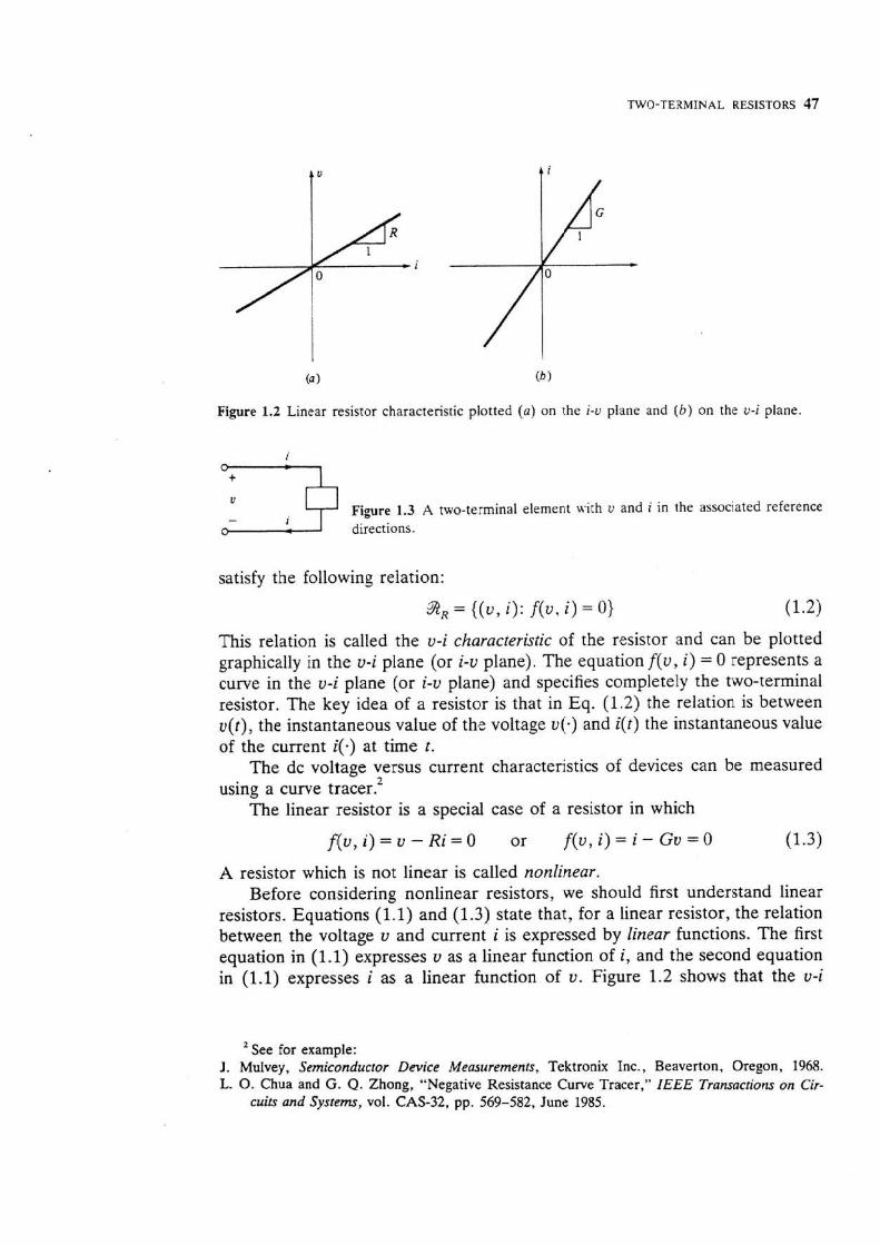
Figure 1.2 Linear resistor characteristic plotted (a) on the i-v plane and ( 6 ) on the v-i plane.
v Figure 1.3 A two-terminal element with v and i in the associated reference directions.
satisfy the following relation:
iRR = {(U, i): f(v, i ) = 0)
This relation is called the v-i characteristic of the resistor and can be plotted graphically in the v-i plane (or i-v plane). The equation f(v, i) = 0 represents a curve in the v-i plane (or i-v plane) and specifies completely the two-terminal resistor. The key idea of a resistor is that in Eq. (1.2) the relation is between v ( t ) , the instantaneous value of the voltage v(-) and i(t) the instantaneous value of the current i(.) at time t .
The dc voltage versus current characteristics of devices can be measured using a curve tracer?
The linear resistor is a special case of a resistor in which
A resistor which is not linear is called nonlinear. Before considering nonlinear resistors, we should first understand linear
resistors. Equations (1.1) and (1.3) state that, for a linear resistor, the relation between the voltage v and current i is expressed by linear functions. The first equation in (1.1) expresses v as a linear function of i, and the second equation in (1.1) expresses i as a linear function of v. Figure 1.2 shows that the v-i
See for example: J . Mulvey, Semiconductor Device Mearurements, Tektronix Inc., Beavenon, Oregon, 1968. L. 0. Chua and G. Q. Zhong, "Negative Resistance Curve Tracer," IEEE Transactions on Cir-
cuits and System, vol. CAS-32, pp. 569-582, June 1985.

TWO-TERMINAL RESISTORS 49
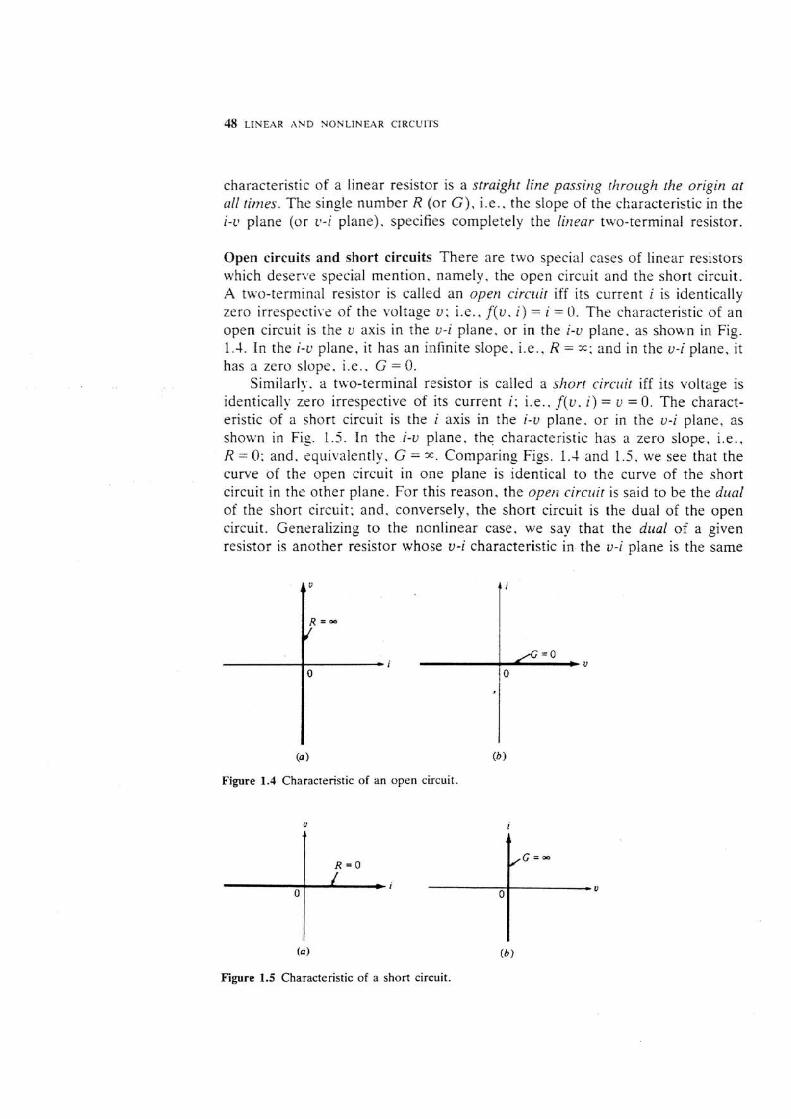
curve as that of the given resistor in the i-v plane. The concept of duality is of utmost importance in circuit theory. It helps us in understanding and analyzing circuits of great generality. We will encounter duality throughout this book.
Exercises 1. A linear resistor of 100 L! is given; what is its dual? 2. If 2, = {(v. i ) : f(v, i ) = v - i3 = 0) specifies a resistor. write down the
relation of the dual resistor. 3. Given the v-i characteristic r of a resistor 9 on the v-i plane, show that
the dual characteristic is obtained by reflecting about the 45" line through the origin.
Power, passive resistors, active resistors, and modeting The symbol for a two-terminal nonlinear resistor 2 is shown in Fig. 1.6. The power delivered ro the resistor at time t by the remainder of the circuit to which it is connected is. from Chap. 1,
If the resistor is linear having resistance R
Thus, the power delivered to a linear resistor is always nonnegative if R 0. We say that a linear resistor is passive iff its resistance is nonnegative. Thus a passive resistor always absorbs energy from the remainder of the circuit.
Also from Eq. (1.4b), the power delivered to a linear resistor is negative if R<O; i.e., as current flows through it, the resistor delivers energy to the remainder of the circuit. Therefore, we call such a linear resistor with negative resistance an active resistor. The characteristic of a linear active resistor is shown in Fig. 1.7; note that the slope is negative. While linear passive resistors are familiar to everyone, linear active resistors are perhaps new to some readers. They are one of the basic circuit elements in the design of negative-
+ Remainder of the U circuit
-
Figure 1.6 Illustrating power delivered to a Figure 1.7 Characteristic of a linear active nonlinear resistor from the remainder of the resistor with resistance R 0. circuit.
resistance amplifiers and oscillators. We ~vill illustrate their applications later. For the present we only wish to mention that the linear active resistor is useful in modeling nonlinear devices and circuits over certain ranges of voltages, currents. and frequencies.
We can easily generalize the above concept to nonlinear resistors. Obvious- ly. from Eq. (1.4~). p ( { ) r 0 if and only if U(() and i ( t ) have the same sign for all t. Thus we call a t~u-terminal resistor ~ ( I S S ~ I ~ Q iff its C-i characteristic lies in the closed first and third quadrants of the L.-i plane or the i-c plane. A resistor is said to be acri\.e if i t is not passive.
At this juncture we wish to recall the concept of modeling introduced in Chap. l . Let us use the term "physical resistor" to refer to the electric device in the laboratory or in a piece of equipment. This is not to be confused with the resistor we defined as a circuit element in Eq. (1 2)). What is remarkable is that for most physical resistors made of metalIic material. we can use the circuit element, a linear passive resistor, to model them almost precisely, i.e., they satisfy Ohm's lalv. The model is good over a large operating range, Only for sscessive voltages or currents, or at ver! high frequencres. is a better model necessary. Often in such a situation the physical resistor fails to be of ordinary use: for example. a physical resistor will burn out if the current exceeds the specified normal operating range. Historically. and in most engineering usage, the term "resistor" is often loosely used to mean the physical resistor, a device which satisfies Ohm's law. In circuit theory we depart from 'the traditional practice and define a resistor as a circrtit element which is specified by a voltage-current relation called the U-i characteristic. This way of defining a resistor has a special significance in modeling electric and electronic devices which, at low frequencies. behave like nonlinear resistors. We nexr turn our attention to nonlinear resistors.
1.2 The Nonlinear Resistor
Recall that a resistor that is not linear is said to be nonlinear. In this section we 1111 first introduce some typical examples of nonlinear resistors and illustrate their properties. We will then point out some essential differences between circuits with linear resistors and those with nonlinear resistors.
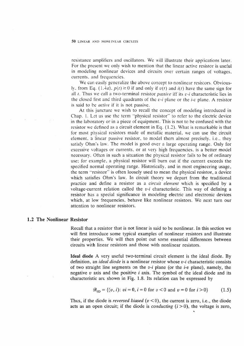
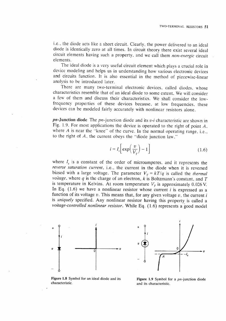
Ideal diode A very useful two-terminal circuit element is the ideal diode. By definition, an ideal diode is a nonlinear resistor whose v-i characteristic consists of two straight line segments on the v-i plane (or the i-L. plane), namely, the negative v axis and the positive i axis. The symbol of the ideal diode and its characteristic arc shown in Fig. 1.8. Its relation can be expressed by
%,,={(v,i): v i = O , i = O f o r v<O and v = O f o r i > O ) (1.5)
Thus, if the diode is reversed biased (v < O ) , the current is zero, i.e., the diode acts as an open circuit; if the diode is conducting (i > O ) , the voltage is zero,
\
TWO-TERMENAL RESISTORS 51
i.e., the diode acts like a short circuit. Clearly. the power delivered to an ideal diode is identically zero at all times. In circuit theory there exist several ideal circuit elements having such a property, and we call them non-energic circuit .
elements. The ideal diode is a very useful circuit element which plays a crucial role in
device modeling and helps us in understanding how various electronic devices and circuits function. It is also essential in the method of piecewise-linear analysis to be introduced later.
There are many two-terminal electronic devices, called diodes. whose characteristics resemble that of an ideal diode to some extent. We wilI consider a few of them and discuss their characteristics. We shall consider the low- frequency properties of these devices because, at low frequencies. these devices can be modeled fairly accurately with nonlinear resistors alone.
pn-Junction diode The pn-junction diode and its v-i characteristic are shown in Fig. 1.9. For most applications the device is operated to the right of point A , where A is near the "knee" of the curve. In the normal operating range. i.e.. .. to the right of A . the current obeys the "diode junction law.
where I, is a constant of the order of microamperes. and it represents the reverse saturnlion current, i.e., the current in the diode when it is reversed biased with a large voltage. The parameter V, = kTJq is called the thermal voltage. where q is the charge of an electron, k is Boltzmann's constant. and T is temperature in Kelvins. A t room temperature V, is approximately 0.036 V. In Eq. (1.6) we have a nonlinear resistor whose current i is expressed as a function of its voltage v. This means that, for any given voltage v, the current i is rtniquely specified. Any nonlinear resistor having this property is called a volrage-controlled nonlinear resistor. While Eq. (1 .6) represents a good model
Figure 1.8 Symbol for an ideal diode and its Figure 1.9 Symbol for a pn-junction diode characteristic. and its characteristic.
for the pn-junction diode at low frequencies, we need to use additional circuit elements. capacitors, inductors, and linear resistors to model it at higher frequencies.
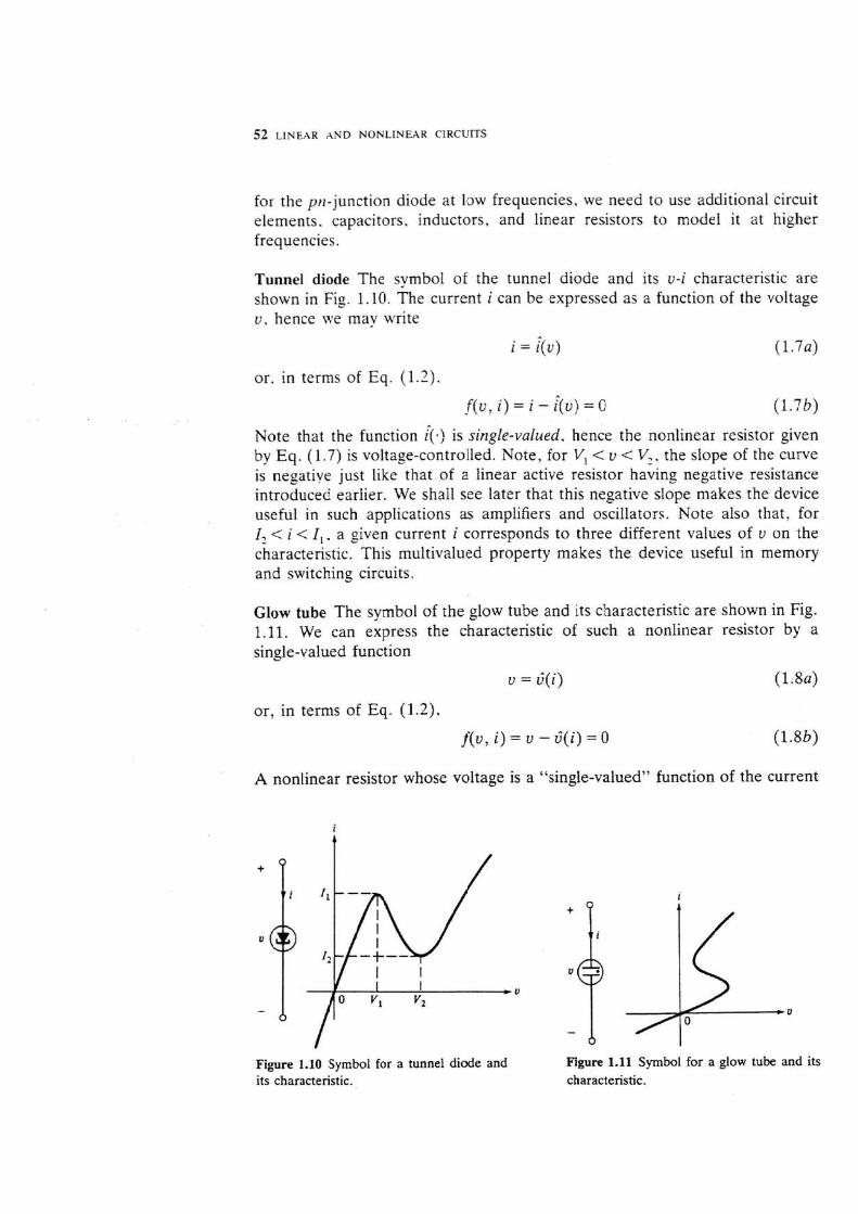
Tunnel diode The symbol of the tunnel diode and its v-i characteristic are shown in Fig. 1.10. The current i can be expressed as a function of the voltage v , hence we may write
i = $U) (1.7a)
or, in terms of Eq. (1.2).
f(v, i) = i - q v ) = 0
Note that the function 4.) is single-valued, hence the nonlinear resistor given by Eq. (1.7) is voltage-controlled, Note, for V* < v < V,. the slope of the curve is negative just like that of a linear active resistor having negative resistance introduced earlier. We shaIl see later that this negative slope makes the device useful in such applications as amplifiers and oscillators. Note also that, for I, < i < I,. a given current i corresponds to three different values of v on the characteristic. This multivalued property makes the device useful in memory and switching circuits.
Glow tube The symbol of the glow tube and its characteristic are shown in Fig. 1.11. We can express the characteristic of such a nonlinear resistor by a single-valued function
v = 6(i> (1.8a)
or, in terms of Eq. (1.21,
f(v, i) = v - ;(i) = O (1.8b)
A nonlinear resistor whose voltage is a "singie-valued" function of the current
Figure 1.10 Symbol for a tunnel diode and Figure 1.11 Symbol for a glow tube and its its characteristic. characteristic.

TWO-TERMINAL RESISTORS 53
is called a crlrrent-corrtro/led resistor. Thus, the glow tube is a current- controlled nonlinear resistor. Since the current is not a (single-valued) function of the voltage. it is not voltage-controlled.
Eote that the ideal diode is neither voltage-controlled nor current- controlled.
Bilateral property In contrast to linear resistors, a nonlinear resistor in general has a v-i characterisric which is not symmetric with respect to the origin of the v-i plane. (See Figs. 1.9 and 1.10.) Consider the tunnel diode in Fig. 1.10. Let us change the reference direction of the current and of the voltage. We redraw the circuit as shown in Fig. 1.12. where i , = - i and v , = -v.
The characteristic jn the v , - i , plane, which corresponds to that of the original two-terminal resistor with the two terminals interchanged, is shown in the figure. For this reason. it is important that the symbol for a nonlinear resistor indicate its orientation. Note that the general s!.mbol for a nonlinear resistor in Fig. 1.13 is dissymmetric with respect to its two terminals: con- sequently. it is possible to specify the correct connection of the two terminals of a nonlinear resistor to a circuit.
The characteristic of a linear resistor is always symmetric with respect to the origin. A circuit element with this kind of symmetry is called bilateral. A bilateral resistor satisfies the property f(v, i) = f(-v, -i) for all (v , i) on its characteristic. A nonlinear resistor may be bilateral, e.g.. have the characteris- tic shown in Fig. 1.14.
Figure 1.12 Characteristic of a tunnel diode with its terminals turned around.
i
Figure 1.13 Symbol for a nonlinear resistor. Figure 1.14 v-i Characteristic of a bilateral nonlinear resistor.
54 LINEAR AND NONLINEAR CIRCUITS
Simple circuits Circuits containing nonlinear resistors have properties totally different from those which have only linear resistors. The following examples illustrate some of the differences.
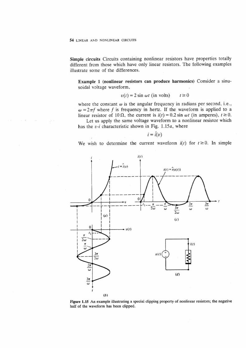
Example I (nonlinear resistors can produce harmonics) Consider a sinu- soidal voltage waveform,
v(r) = 2 sin of (in volts) t r 0
where the constant w is the angular frequency in radians per second, i.e., w = 2 r f where f is frequency in hertz. If the waveform is applied to a linear resistor of 10 a, the current is i(t) = 0.2 sin wt (in amperes), t 2 0.
Let us apply the same voltage waveform to a nonlinear resistor which has the v-i characteristic shown in Fig. 1.15a, where
i = $v>
We wish to determine the current waveform ijt) for t r 0. In simple
Figure 1.15 An example illustrating a special clipping property of nonlinear resistors; the negative half of the waveform has been clipped.

TWO-TERMINAL RESISTORS 55
nonlinear circuit analysis a graphic method is often useful. Let us plot the voltage waveform v(.) as shown in Fig. 1.15b with the r axis lined up with the i axis of Fig. 1.150. Then it is easy to obtain the current i ( t ) shown in Fig. 1 . 1 5 ~ by transcribing points on the voltage waveform u ( t ) at r = 0. r , . - ,'?m. t rim. 3;ii2w. etc., through the v-i curve of the nonlinear resistor. The resulting current waveform i ( - ) is again a periodic function with period 2ir lo; hence i t can be expressed in terms of a Fourier series
i ( t ) = I,, + !, sin kwr k
( 1-91
It contains. besides the fundamental sinusoid, higher harmonics. i.e.. the sinusoidal terms in Eq. ( 1.9) with k > l. What is especially important to note is that. unlike the voltage waveform v(.) . the current waveform i(.) has a direct crlrrenr (dc) component I,,. The term I,, in Eq. (1 .9) is equal to the average value of the current waveform i(.) over a complete period. This dc component can be filtered out with a simple low-pass filter. This. of course, is the basis of all rectifier circuits which convert alternating current to direct current.
Example 2 (piecewise-linear approximation) Another basic method of non- linear circuit analysis is the use of piecewise-linear approximation. The v-i curve in Fig. 1 .15~ can be roughly approximated by two linear segments as shown in Fig. 1.16. With this simple approximation. the current waveform can be obtained immediately. For v negative, i is identically zero. For v positive, the nonlinear resistor behaves like a linear resistor with conduct- ance G. Thus the waveform is given by
2 n ~ (271 + 1)n ( 2 G s i n o t for - s t s
(2n + 1 ) r (2n + 2)n for S l 5
where n runs through nonnegative integers. The result is of course different from that obtained by the graphic method. However, had we used
i nonlinear characteristic.
more linear segments to approximate the v-i curve, we could have obtained a solution closer to the current waveform shown in Fig. 1.15. The subject of piecewise-tinear approximation will be treated in greater detail later in the chapter.
Example 3 (homogeneity and additivityf In this example we will compare the currents in a linear resistor whose characteris~ic is
and in n nonlinear resistor whose characteristic is
The subscript f denotes linear and the subscript n denotes nonlinear. Let us consider three different constant input voltages: v, = 1 V, v, = k V, and L!: = v ; + L', = I + k V. For the linear resistor. from Eq. (1. IOU), we have i,, = Q . l A . i,:=0.1 X k A , and i , , = U . l + O . f x k A . Clearly
and ii3 = &(U[ + v?) = ;((vI) + It (U?) (1. l lb)
Equation ( l . l la) states the homogeneity property of a linear function, while Eq. (l. l l b ) states the additivity properry .
Nest, let us consider the nonlinear resistor defined by Eq. (1.10b). Setting U , = l V, v, = k V, and v, = U , + U, V, we obtain successively in, = 0.12A. i , ,=O.lx k + 0 . 0 2 x k 3 A , and i ,3=0.1(1+k)+0.02(1+k) 'A. Clearly
and
Thus in general for nonlinear resistors, neither the homogeneity property nor the additivity property holds.
1.3 Independent Sources
In circuit theory, independent sources play the same role as external forces in mechanics. Independent sources are circuit elements which are used to model such devices as the battery and the signal generator, The two independent sources we will introduce in this section are the independent voltage source and the independent current source. For convenience, however, we shall often omit the adjective "independent" and simply use the terms "voltage source" and "current source."
Independent voltage source A two-terminal element is called an independent voltage source if the voltage across it is a given waveform v,(.) irrespective of
WO-TERMINAL RESISTORS 57
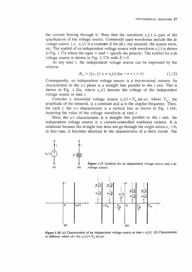
the current flowing through it. Note that the waveform v,(-) is part of the specification of the voltage source. Commonly used waveforms include the dc tpolrage source, i.e.. v,(t) is a constant E for all t , the sinusoid. the square wave. etc. The symbol of an independent voltage source with waveform v,(.) is shown in Fig. 1.17~ where the signs + and - specify the polarity. The symbol for a dc voltage source is shown in Fig. 1.17b with E > 0.
At any time r , the independent voltage source can be expressed by the relation
aU3 = {(U, i): v = vS(f) for - X < i < X ) (1.12)
Consequently, an independent voltage source is a two-terminal resistor. Its characteristic in the v-i plane is a straight line parallel to the i axis. This is shown in Fig. 1.18a, where vs(r) denotes the voltage of the independent voltage source at time r.
Consider a sinusoidal voltage source v,(t) = Vm sin wr. where V,. the amplitude of the sinusoid. is a constant and w is the angular frequency. Then. for each t , the v-i characteristic is a vertical line as shown in Fig. l . lSb, depicting the value of the voltage waveform at time r.
Since the U-i characteristic is a straight line parallel to the i axis. the independent voltage source is a current-controlled nonlinear resistor. It is nonlinear because the straight line does not go through the origin unless v, = 0; in that case. it becomes identical to the characteristic of a short circuit. The
E -
-h Figure 1.17 Symbols for an independent voltage source and a dc (8 1 (a) ,voltage source.
Figure 1.18 (a) Characteristic of an independent voltage source at time r, v,([). ( b ) Characteristic at different values of t for v,([) = V,,, sin wt.
58 LINEAR A N D NONLINE,4R CIRCUKS
property that an independent voltage source v, becomes a short circuit (zero resistance) if v , = 0 is very important in circuit analysis. We shall use this property from time to time throughout the book.
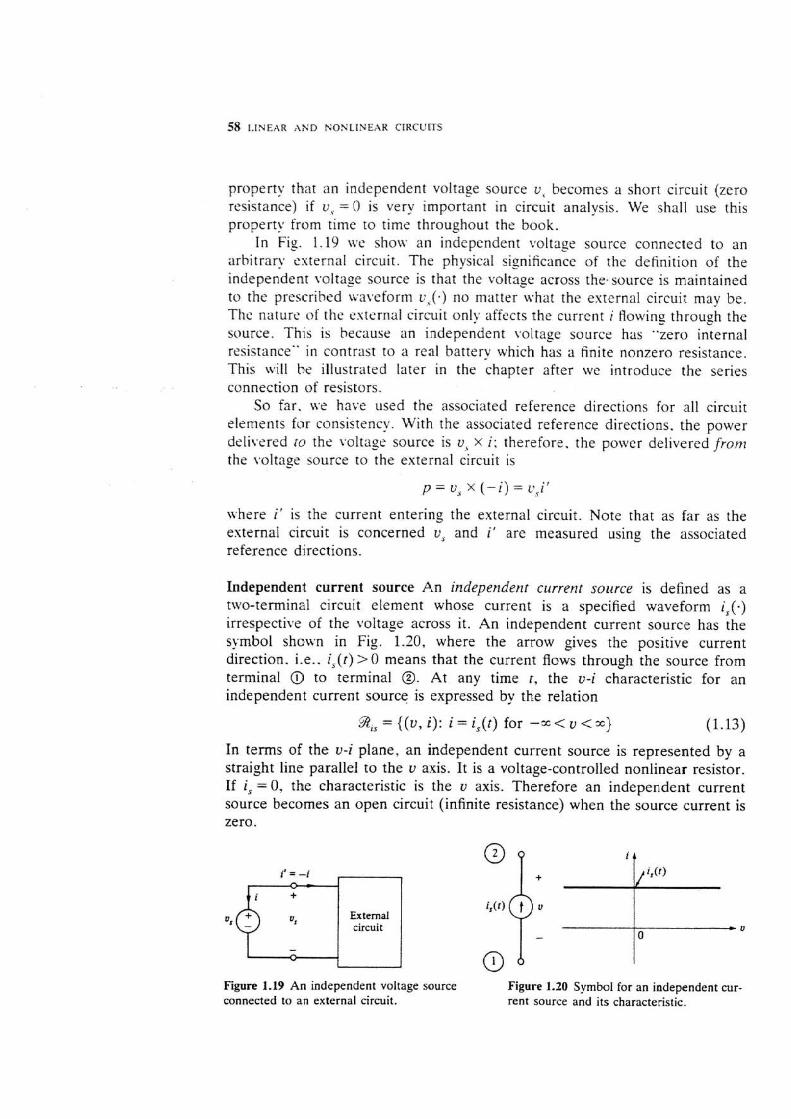
In Fig. 1.19 we show an independent votbage source connected to an arbitrary esternal circuit. The physical significance of the definition of the independent voitase source is that the voltage across the.source is maintained to the prescribed ivaveforrn v,(.) no matter what the esternal circuit may be. The nature of the external circuit only affects the current i flowing through the source. This is because an independent voltage source has "zero internal resistance" in contrast to a real battery which has a finite nonzero resistance. This will be illustrated later in the chapter after we introduce the series connection of resistors.
So far. we have used the associated reference directions for all circuit elements for consistency. With the associated reference directions. the power delitrered ro the voltage source is v, X i: therefore. the power delivered from the voltage source to the esternal circuit is
where i' is the current entering the external circuit. Note that as far as the esternal circuit is concerned v, and i ' are measured using the associated reference directions.
Independent current source An independerzr crrrrent source is defined as a two-terminal circuit element whose current is a specified waveform i , ( . ) irrespective of the voltage across it. An independent current source has the symbol shown in Fig. 1.20, where the arrow gives the positive current direction. i.e.. i , ( r ) > 0 means that the current flows through the source from terminal @ to terminal B. At any time r , the v-i characteristic for an independent current source is expressed by the relation
9, = {(v, i): i = i ,(t) for - X v < x ) (1.13)
In te rns of the v-i plane, an independent current source is represented by a straight line parallel to the v axis. It is a voltage-controlled nonlinear resistor. If is = 0. the characteristic is the v axis. Therefore an independent current source becomes an open circuit (infinite resistance) when the source current is zero.
Figure 1.19 An independent voltage source Figure 1.20 Symbol for an independent cur- connected to an external circuit. rent source and its characteristic.
i &
External circuit
1 i,(t)
, U 0
