linear attenuation coefficients and gas holdup ... · linear attenuation coefficients and gas...
TRANSCRIPT

Linear Attenuation Coefficients and Gas Holdup Distributions in Bubble Column
with Vertical Internal for Fischer-Tropsch (FT) Synthesis
Abbas J. Sultan, Laith S. Sabri, and Muthanna H. Al-Dahhan† †Multiphase Reactors Engineering and Applications Laboratory (mReal)
† Department of Chemical and Biochemical Engineering, Missouri University of Science and
Technology, Rolla, MO 65409-1230. USA
4/26/2017 1

4/26/2017 2
Introduction
Motivations
Results and Discussion
Remarks
Acknowledgment
Multiphase Reactors Engineering and
Applications Laboratory (mReal)
Presentation Outline

4/26/2017 3
Coal
Biomass
Natural Gas
Fuel
& Chemicals
Gasification Syngas
Processing
Fischer-
Tropsch Synthesis
Syncrude
Refining & Upgrading
X L G
Introduction & Motivation
The conversion of natural and bio gas, coal, and biomass to liquid fuels and chemicals vis synthesis gas is currently of
interests to the energy and chemical industries which represents a valuable addition to diversifying in fuels and products
resources.
The key route for the conversion synthesis gas to liquid fuels and chemicals (GTL) technology is the Fisher-Tropsch
(FT) synthesis where the reaction of syngas (H2 and CO) over catalyst into liquid hydrocarbons takes place. FT synthesis
is highly exothermic and hence intense heat exchanging tubes (internals) are needed to control the temperature.
H2+CO (syngas) F-T waxes (C1-C100+)
H2O Water steam

4/26/2017 4
Multiphase Reactors Engineering and
Applications Laboratory (mReal)
Bubble/Slurry bubble column reactor with vertical dense heat
exchanging tubes is one of the reactors of choice to conduct the highly
exothermic FT reaction.
The presence of the dense heat exchange tubes (internals) impacts the
hydrodynamics and mixing behavior of the reactor in a very complex
way and hence, it will affect the performance, selectivity and the yield.
The understanding of such complexity has been completely lacking
due to lack of implementing advanced measurement techniques.
Slurry bubble columns with vertical internals
Gas holdup distribution is the one of the important hydrodynamic
parameters governing the dynamic of the bubble/slurry bubble columns
where gas holdup drives the liquid circulation, and hence the rate of
mixing, mass, and heat transfer.
There is a lack of detailed investigation to understand the effect of the
intense internals on the gas holdup distribution.
Therefore, the focus of this work is to investigate, visualize, and quantify
for the first time the influence of the size, and configurations of the
intense heat exchanging tubes (internals) at wide range of the superficial
gas velocity on the time-averaged cross-sectional gas holdup distribution
and their radial/diametrical profiles by implementing non-invasive
gamma-ray computed tomography (CT) technique.
Industrial heat exchanging tubes (internals)

Dynamic level, L/D=10.3 (158 cm)
14 cm ID
183 cm
7.62 cm
Scan level, L/D=5.1 (78 cm) 2.54 cm O.D Plexiglas
internals Circular configuration
(supports)
Distributor
Drain
Compressed air in
30 cm
4/26/2017 5
Schematic diagram and photo of the stainless steel distributor (perforated plate)
Schematic diagrams and pictures of the circular configurations (spacers/supports)
for 0.5, and 1-inch internals
• The internals was designed to
cover 25% of the cross-
sectional area of the column to
mimic the bundle of heat
exchanging tubes used in FT
synthesis .
Experimental step up
Schematic diagram of 6-inch bubble column equipped with vertical internals
Multiphase Reactors Engineering and
Applications Laboratory (mReal)

To the data
acquisition
system .60
samples at 10
Hz, which took
about 8.25 hours
for a full scan
Cs-137 source
Source collimator
Threaded rods
Aluminum
structure
Motor
Circular
plate
Square
plate
Steeper
motor
Chain
driver
15 NaI detectors
Detectors collimator
(2 mm × 5 mm)
Bubble column
with internals
Flowmeters
Cs-137 source
Source collimator
Bubble column with internals
Detectors collimator
NaI detector
CO-60 source
Source collimator
Detector collimator
15 NaI detectors
Bubble column with internals
Top supporter
Bottom supporter
Lead shield
CS-137 source
Schematic diagram of single gamma-ray computed tomography (CT) technique
with bubble column
Photo of dual-source gamma-ray computed tomography (CT) technique with
bubble column during CT scan
4/26/2017 6
Gamma–ray Computed Tomography (CT) Technique
Multiphase Reactors Engineering and
Applications Laboratory (mReal)
Scanning a bubble column equipped with dense vertical internals
4/26/2017 7
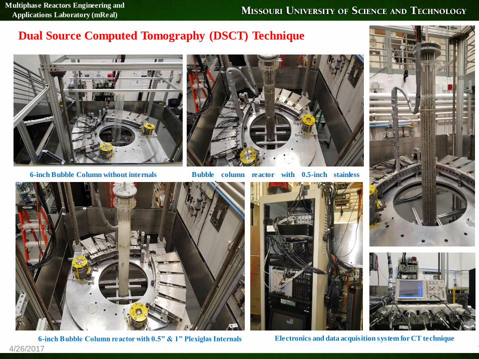
Dual Source Computed Tomography (DSCT) Technique
6-inch Bubble Column without internals Bubble column reactor with 0.5-inch stainless
internals
6-inch Bubble Column reactor with 0.5” & 1” Plexiglas Internals
Multiphase Reactors Engineering and
Applications Laboratory (mReal)
Electronics and data acquisition system for CT technique

4/26/2017 8
0
0.02
0.04
0.06
0.08
0.1
-1 -0.8 -0.6 -0.4 -0.2 0 0.2 0.4 0.6 0.8 1Lin
ear
att
enu
ati
on
co
effi
cien
t,cm
-
1
Dimensionless radius,r/R (-)
0
0.02
0.04
0.06
0.08
0.1
-1 -0.8 -0.6 -0.4 -0.2 0 0.2 0.4 0.6 0.8 1Lin
er a
tten
ua
tio
n c
oef
fici
ent,
cm-1
Dimensionless,radius,r/R (-)
0
0.02
0.04
0.06
0.08
0.1
-1 -0.8 -0.6 -0.4 -0.2 0 0.2 0.4 0.6 0.8 1Lin
ear
att
enu
ati
on
co
effi
cien
t,cm
-
1
Dimensionless radius,r/R(-)
0
0.02
0.04
0.06
0.08
0.1
-1 -0.8 -0.6 -0.4 -0.2 0 0.2 0.4 0.6 0.8 1
Lin
ear
att
enu
ati
on
co
effi
cien
t,cm
-
1
Dimensionless radius,r/R (-)
Multiphase Reactors Engineering and
Applications Laboratory (mReal)
CT Scan Validation by
Phantom
Cross-sectional linear attenuation coefficient distribution(cm-1), and
diameter profile for phantom Case I for case I (empty phantom)
Cross-sectional linear attenuation coefficient
distribution(cm-1), and diameter profile for phantom
case II (the inner cylinder filled with water)
Cross-sectional linear attenuation coefficient distribution(cm-1), and diameter
profile for phantom for case III (the outer cylinder filled with water)
Cross-sectional linear attenuation coefficient,
distribution (cm-1), and diameter profile of linear
for phantom for case IV (the inner and outer
cylinders filled with water)

4/26/2017 9
Results and Discussion
Linear attenuation coefficient distribution for a bubble column without internals: (a) empty column,
(b) column filled with water, and (c) column with air-water at superficial gas velocity 45 cm/s
Linear attenuation coefficient distribution for a bubble column equipped with 0.5-inch internals: (a) empty
column, (b) column filled with water, and (c) column with air-water at superficial gas velocity 45 cm/s
Linear attenuation coefficient distribution for a bubble column equipped with 1.0-inch internals: (a) empty
column, (b) column filled with water, and (c) column with air-water at superficial gas velocity 45 cm/s
Linear attenuation coefficient distribution (μ, cm-1 )for a bubble column with and without internals
Multiphase Reactors Engineering and
Applications Laboratory (mReal)
The reconstructed linear
attenuation images clearly show
that the CT technique was able to
capture and reproduce the
arrangement and location of each
of the internals as well as of the
column wall.
These images confirm the quality
of this CT technique and also the
image reconstruction algorithm
(AM). Hence, the CT is capable
of capturing a small
maldistribution in the multiphase
reactor if it exists and it provides
reliable cross-sectional gas
holdup distribution to validate
CFD simulations and
hydrodynamics models.
4/26/2017 10
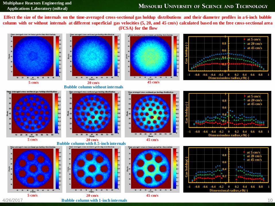
Effect the size of the internals on the time-averaged cross-sectional gas holdup distributions and their diameter profiles in a 6-inch bubble
column with or without internals at different superficial gas velocities (5, 20, and 45 cm/s) calculated based on the free cross-sectional area
(FCSA) for the flow
0
0.2
0.4
0.6
0.8
1
-1 -0.8 -0.6 -0.4 -0.2 0 0.2 0.4 0.6 0.8 1
Gas
hold
up (
-)
Dimensionless radius,r/R(-)
at 5 cm/s
at 20 cm/s
at 45 cm/s
0
0.2
0.4
0.6
0.8
1
-1 -0.8 -0.6 -0.4 -0.2 0 0.2 0.4 0.6 0.8 1
Gas
hold
up
(-)
Dimensionless radius,r/R(-)
at 5 cm/s at 20 cm/s at 45 cm/s
0
0.2
0.4
0.6
0.8
1
-1 -0.8 -0.6 -0.4 -0.2 0 0.2 0.4 0.6 0.8 1G
as
hold
up(-
)
Dimensional radius,r/R(-)
at 5 cm/s at 20 cm/s at 45 cm/s
Bubble column without internals
Bubble column with 0.5-inch internals
Bubble column with 1-inch internals
Multiphase Reactors Engineering and
Applications Laboratory (mReal)
5 cm/s 20 cm/s 45 cm/s
5 cm/s 20 cm/s 45 cm/s
5 cm/s 20 cm/s 45 cm/s
4/26/2017 11
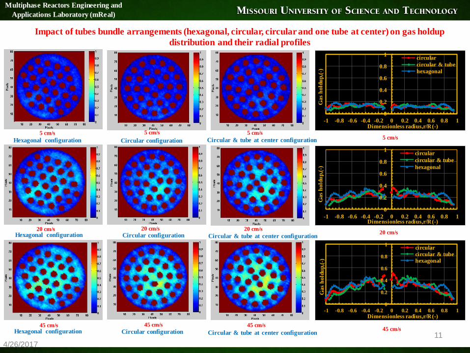
Impact of tubes bundle arrangements (hexagonal, circular, circular and one tube at center) on gas holdup
distribution and their radial profiles
0
0.2
0.4
0.6
0.8
1
-1 -0.8 -0.6 -0.4 -0.2 0 0.2 0.4 0.6 0.8 1
Gas
hold
up,(
-)
Dimensionless radius,r/R (-)
circular
circular & tube
hexagonal
Multiphase Reactors Engineering and
Applications Laboratory (mReal)
0
0.2
0.4
0.6
0.8
1
-1 -0.8 -0.6 -0.4 -0.2 0 0.2 0.4 0.6 0.8 1
Gas
ho
ldu
p,(
-)
Dimensionless radius,r/R (-)
circular
circular & tube
hexagonal
0
0.2
0.4
0.6
0.8
1
-1 -0.8 -0.6 -0.4 -0.2 0 0.2 0.4 0.6 0.8 1
Gas
hold
up
,(-)
Dimensionless radius,r/R (-)
circularcircular & tubehexagonal
5 cm/s
20 cm/s
45 cm/s
5 cm/s
20 cm/s
45 cm/s
5 cm/s
20 cm/s
45 cm/s
5 cm/s
20 cm/s
45 cm/s
Hexagonal configuration
Hexagonal configuration
Hexagonal configuration
Circular configuration
Circular configuration
Circular configuration
Circular & tube at center configuration
Circular & tube at center configuration
Circular & tube at center configuration
4/26/2017 12
0
0.2
0.4
0.6
0.8
1
-1 -0.8 -0.6 -0.4 -0.2 0 0.2 0.4 0.6 0.8 1
Gas h
old
up(-
)
Dimensionless radius,r/R(-)
without internals
with 0.5-inch internals
with 1.0-inch internals
0
0.2
0.4
0.6
0.8
1
-1 -0.8 -0.6 -0.4 -0.2 0 0.2 0.4 0.6 0.8 1
Gas h
old
up,(
-)
Dimensionless radius,r/R (-)
circular
circular & tube
hexagonal
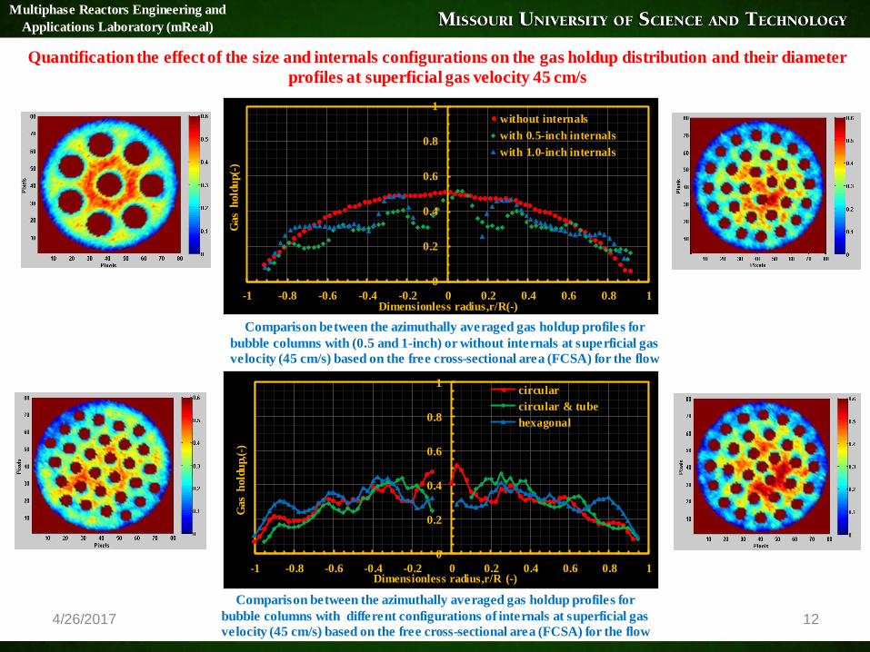
Comparison between the azimuthally averaged gas holdup profiles for
bubble columns with (0.5 and 1-inch) or without internals at superficial gas
velocity (45 cm/s) based on the free cross-sectional area (FCSA) for the flow
Comparison between the azimuthally averaged gas holdup profiles for
bubble columns with different configurations of internals at superficial gas
velocity (45 cm/s) based on the free cross-sectional area (FCSA) for the flow
Multiphase Reactors Engineering and
Applications Laboratory (mReal)
Quantification the effect of the size and internals configurations on the gas holdup distribution and their diameter
profiles at superficial gas velocity 45 cm/s

4/26/2017 13
Remarks
For the first time, cross-sectional gas holdup distributions and their diametrical profiles were visualized and quantified at
different internal sizes, configurations, and superficial gas velocities to study and assess these parameters.
The reconstructed CT images show that the bubble columns equipped with or without internals displayed a symmetric
cross-sectional gas holdup distribution for all studied superficial gas velocities. However, the bubble column with 1-inch
internals (sparse arrangement) produced a more symmetric distribution than the bubble column equipped with 0.5-inch
internals (dense arrangement).
The design of the configurations of internals affect significantly on the gas holdup distribution especially at the core and
wall region of the reactor
The reconstructed linear attenuation coefficients (μ, cm-1 ) values are close to the theoretical values. The comparison
shows good agreement of these for empty columns and bubble column equipped with internals
The gamma-ray computed tomography technique was capable of capturing the wall thickness of a column and the
internals.
The present work provides, for the first time, benchmarking data to validate reactor models and computational fluid
dynamics (CFD) simulations and consequently will facilitate the design and scale-up of bubble column with internals.
Multiphase Reactors Engineering and
Applications Laboratory (mReal)

The authors gratefully acknowledge the financial support in the form of a scholarship provided
by the Higher Committee for Education Development in Iraq (HCED), Ministry of Higher
Education and Scientific Research (Iraq), and the funds provided by Missouri S&T and
Professor Dr. Muthanna Al-Dahhan to develop the CT technique, the experimental set-up, and
to perform the present study. Also, the authors would like to thank Dr. Fadha Ahmed,and Mr.
Jianbin Shao for his help with the gamma-ray computed tomography (CT) technique.
Acknowledgements
4/26/2017 14
Multiphase Reactors Engineering and
Applications Laboratory (mReal)

Computed Tomography (CT)
S10
For Phase Distribution Measurements

Radioactive Particle Tracking (RPT)
R1
R2
δ
Sc
Parylene N
Sc46 particle coated with
parylene-N, tracking solids
Sc46 particle in polypropylene ball,
tracking liquid
Picture of RPT
RPT
Calibration
Tracer particle
holding assembly
In Situ
Manual
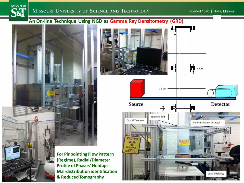
35 cm
35 cm
0.625
35 cm
3.61
Detector
An On-line Technique Using NGD as Gamma Ray Densitometry (GRD)
Source
For Pinpointing Flow Pattern (Regime), Radial/Diameter Profile of Phases’ Holdups Mal-distribution identification & Reduced Tomography
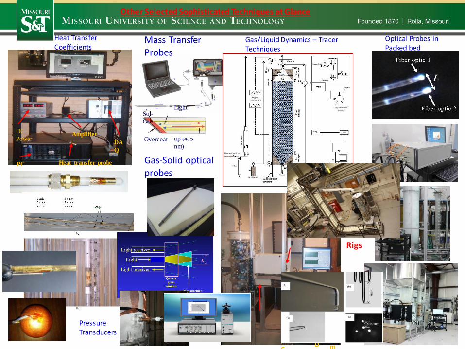
Other Selected Sophisticated Techniques at Glance
Heat Transfer Coefficients
Heat transfer probe
DC
Power
PC
DA
Q
Amplifier
Mass Transfer Probes
Gas-Solid optical probes
Pressure Transducers
FID P
C
Am
Pebble bed unit
Gas/Liquid Dynamics – Tracer Techniques
Optical Probes in Packed bed
Light
going
to the
probe
tip (475
nm)
Sol-
Gel
Overcoat
Rigs

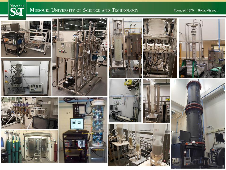
Radioisotope Laboratory for Advancing Industrial Multiphase Processes
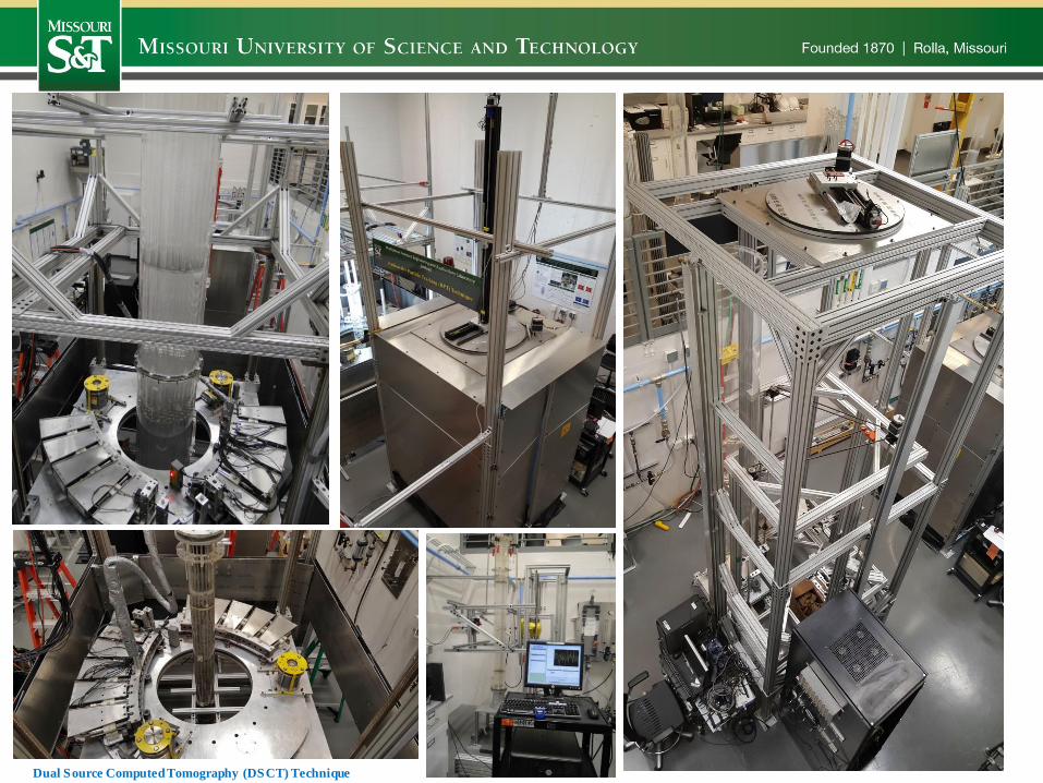
Dual Source Computed Tomography (DSCT) Technique

Non-Radioisotope Laboratory for Advancing Industrial Multiphase Processes

Microalgae Laboratory
(Biological Lab)

4/26/2017 24
Multiphase Reactors Engineering and
Applications Laboratory (mReal)