linear bushings and shafts inch series - bosch rexroth … · linear bushings and shafts inch...
TRANSCRIPT
Linear Bushings and ShaftsInch Series
The Drive & Control Company
2 Bosch Rexroth Corporation Bushings and Shafts Inch Series RA 99 110 (2008.06)
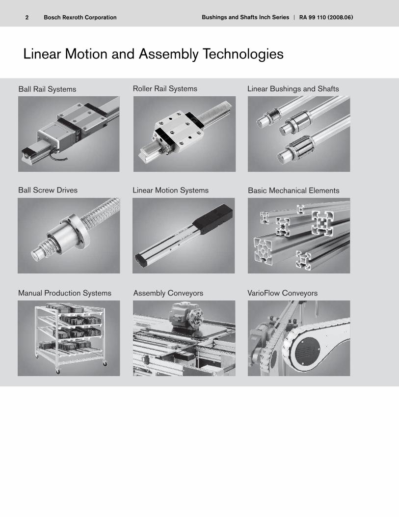
Linear Motion and Assembly Technologies
Ball Rail Systems Roller Rail Systems Linear Bushings and Shafts
Ball Screw Drives Linear Motion Systems Basic Mechanical Elements
Manual Production Systems Assembly Conveyors VarioFlow Conveyors
3Bosch Rexroth CoporationRA 99 110 (2008.06) Bushings and Shafts Inch Series
Product Overview 4Quick Reference 6 Dimensions and Load Capacities
General Technical Data & Mounting Instructions 8Standard Linear Bushings 16 R0750-../ R0752-../ R0753-..
Super Linear Bushings 24 R0755-../ R0756-..
Cast Iron Pillow Block Sets 30 R1750-../ R1752-../ R1753-..
Aluminum Pillow Block Sets 38- Single Sets R1755-../ R1756-../ R1757-..
- Twin Sets R1760-../ R1762-../ R1763-..
Precision Steel Shaft 50 R1700-../ R1771-..
Shaft Support Rail Assemblies 59 R1769-../R1770-..
Shaft Support Rails 62- High Profi le R1767-..
- Low Profi le R1768-..
Shaft Support Blocks 65 R1759-..
External Retaining Rings 66 XR-..A / XRS-..A
4 Bosch Rexroth Corporation Bushings and Shafts Inch Series RA 99 110 (2008.06)
Linear Bushings Standard R0750-..to R0753-.. - closed/adjustable/open - precision bore - with or without internal seals - corrosion-resistant
PRODUCT TYPE FEATURES
Super R0755-..to R0756-.. - closed/open - self-aligning adjustable bore - with or without internal seals - light weight/high load capacity
Linear Pillow Cast Iron Blocks R1750-..to R1753-.. - closed/adjustable/open Block Sets - rigid cast iron - self-aligning sleeve - standard bushing insert
Linear Shaft Aluminum blocks - closed/adjustable/open and Assemblies Single R1755-..to R1757-.. - super bushing insert Twin R1760-..to R1763-.. - lightweight - anodized blocks Precision Steel Shaft R1700-..to R1771-.. - carbon/stainless steel - plain or pre-drilled - class L Shaft Support - aluminum/steel Rail Assemblies R1769-.. to R1770-..
Shaft Supports Support Rails R1767-..to R1768-.. - aluminum/steel material - with or without base fl ange - standard and low profi le - rigid cast iron block
5Bosch Rexroth CoporationRA 99 110 (2008.06) Bushings and Shafts Inch Series
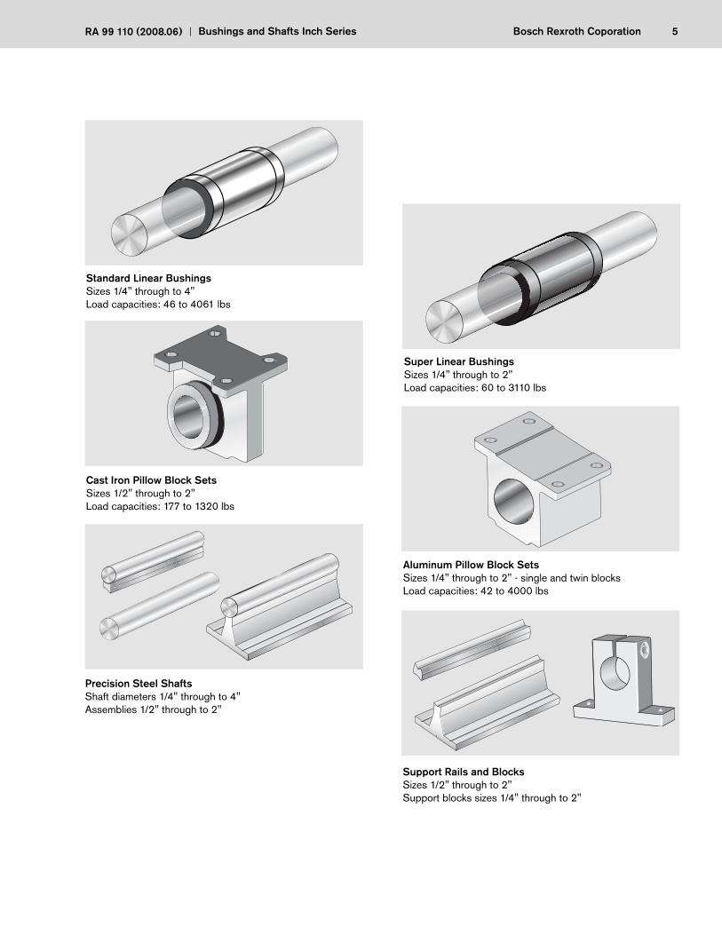
Standard Linear BushingsSizes 1/4" through to 4"Load capacities: 46 to 4061 lbs
Support Rails and BlocksSizes 1/2" through to 2" Support blocks sizes 1/4" through to 2"
6 Bosch Rexroth Corporation Bushings and Shafts Inch Series RA 99 110 (2008.06)
L
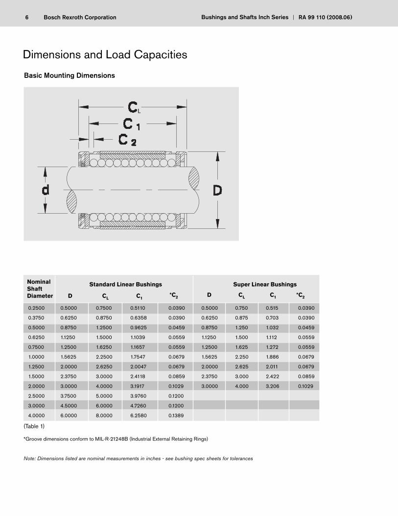
(Table 1)
*Groove dimensions conform to MIL-R-21248B (Industrial External Retaining Rings)
Note: Dimensions listed are nominal measurements in inches - see bushing spec sheets for tolerances
Nominal ShaftDiameter
Standard Linear Bushings Super Linear Bushings
D CL C1*C2 D CL C1 *C2
0.2500
0.3750
0.5000
0.6250
0.7500
1.0000
1.2500
1.5000
2.0000
2.5000
3.0000
4.0000
0.5000
0.6250
0.8750
1.1250
1.2500
1.5625
2.0000
2.3750
3.0000
3.7500
4.5000
6.0000
0.7500
0.8750
1.2500
1.5000
1.6250
2.2500
2.6250
3.0000
4.0000
5.0000
6.0000
8.0000
0.5110
0.6358
0.9625
1.1039
1.1657
1.7547
2.0047
2.4118
3.1917
3.9760
4.7260
6.2580
0.0390
0.0390
0.0459
0.0559
0.0559
0.0679
0.0679
0.0859
0.1029
0.1200
0.1200
0.1389
0.5000
0.6250
0.8750
1.1250
1.2500
1.5625
2.0000
2.3750
3.0000
0.750
0.875
1.250
1.500
1.625
2.250
2.625
3.000
4.000
0.515
0.703
1.032
1.112
1.272
1.886
2.011
2.422
3.206
0.0390
0.0390
0.0459
0.0559
0.0559
0.0679
0.0679
0.0859
0.1029
7Bosch Rexroth CoporationRA 99 110 (2008.06) Bushings and Shafts Inch Series
Load Capacities
Load Correction Factor (fmax)
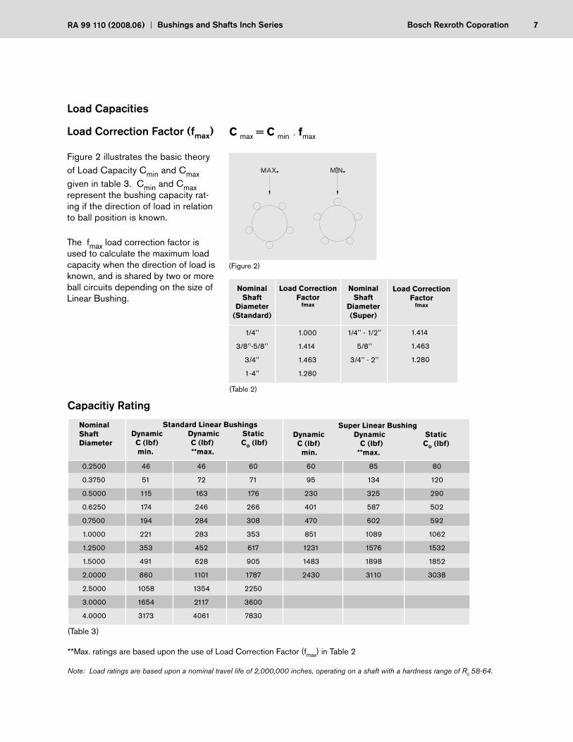
Figure 2 illustrates the basic theory of Load Capacity Cmin and Cmax given in table 3. Cmin and Cmax represent the bushing capacity rat-ing if the direction of load in relation to ball position is known.
The fmax load correction factor is used to calculate the maximum load capacity when the direction of load is known, and is shared by two or more ball circuits depending on the size of Linear Bushing.
NominalShaft
Diameter(Standard)
Load Correction Factor
fmax
(Table 2)
1/4’’
3/8’’-5/8’’
3/4’’
1-4’’
1.000
1.414
1.463
1.280
Nominal Shaft Diameter
Standard Linear BushingsDynamic Dynamic Static C (lbf) C (lbf) Co (lbf) min. **max.
Super Linear Bushing Dynamic Dynamic Static C (lbf) C (lbf) Co (lbf) min. **max.
(Table 3)
**Max. ratings are based upon the use of Load Correction Factor (fmax) in Table 2
Note: Load ratings are based upon a nominal travel life of 2,000,000 inches, operating on a shaft with a hardness range of Rc 58-64.
0.2500
0.3750
0.5000
0.6250
0.7500
1.0000
1.2500
1.5000
2.0000
2.5000
3.0000
4.0000
46
51
115
174
194
221
353
491
860
1058
1654
3173
46
72
163
246
284
283
452
628
1101
1354
2117
4061
60
71
176
266
308
353
617
905
1787
2250
3600
7830
60
95
230
401
470
851
1231
1483
2430
85
134
325
587
602
1089
1576
1898
3110
80
120
290
502
592
1062
1532
1852
3038
NominalShaft
Diameter(Super)
Load Correction Factor
fmax
1/4’’ - 1/2’’
5/8’’
3/4’’ - 2’’
1.414
1.463
1.280
(Figure 2)
C max = C min fmax ·
Capacitiy Rating

8 Bosch Rexroth Corporation Bushings and Shafts Inch Series RA 99 110 (2008.06)
Calculating Travel Life
In determining travel life of a Linear Bushing, there are several factors to be considered. These factors are the load rating of linear bushing, resultant forces acting on the linear bushing, shaft hardness, and operating temperature.
The values for dynamic load capacities (C) have been calculated based on a nominal travel life of 2,000,000 inches.
The formula for calculating travel life is as follows:
L = [ C • fH • ft]3 • 2 • 106
Lh = 2 • s • n • 60
Shaft Hardness Factor - fH
0 10 20 30 40 50 60 70
1,0
0,8
0,6
0,4
0,2
0
L = nominal travel life (inches)
C = basic dynamic load rating (lbs)
P = resultant of external forces (lbs)
fH = shaft hardness factor
ft = temperature factor
Lh = nominal rated life (hrs)
s = stroke length (inches)
n = stroke repetition rate (full cycle) (min-1)
Shaft hardness, Rockwell C
Har
dnes
s fa
ctor
f H
Chart for determination of hardness factor fH
Bushing temperature, oF 212 255 300 345 395Temperature factor, ft 1 0.95 0.90 0.84 0.73
(Table 4)
General Technical Data & Mounting Instructions
P
L
9Bosch Rexroth CoporationRA 99 110 (2008.06) Bushings and Shafts Inch Series
P P
fH ft fL
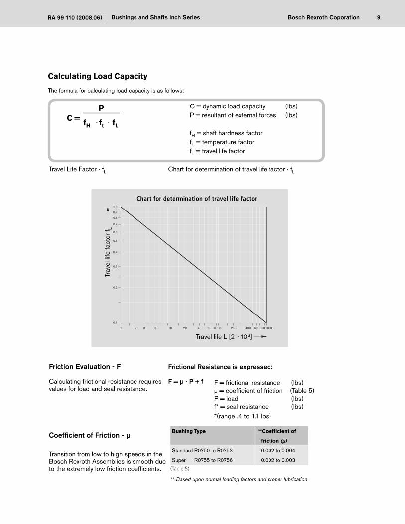
Travel Life Factor - fL Chart for determination of travel life factor - fL
Friction Evaluation - F Frictional Resistance is expressed:
Calculating frictional resistance requires F = μ P + f values for load and seal resistance.
Coeffi cient of Friction - μ
Transition from low to high speeds in theBosch Rexroth Assemblies is smooth due to the extremely low friction coeffi cients.
1 2 3 5 10 10008006004002006020 40 80 100
1.0
0,9
0.8
0.7
0.6
0.5
0.4
0.3
0.2
0.1
Trav
el li
fe fa
ctor
f L
Chart for determination of travel life factor
Calculating Load Capacity
The formula for calculating load capacity is as follows:
C = dynamic load capacity (lbs)P = resultant of external forces (lbs)
fH = shaft hardness factorft = temperature factorfL = travel life factor
F = frictional resistance (lbs)μ = coeffi cient of friction (Table 5)P = load (lbs)f* = seal resistance (lbs)*(range .4 to 1.1 lbs)
C =
(Table 5)
** Based upon normal loading factors and proper lubrication
Bushing Type **Coeffi cient of
friction (μ)
Standard R0750 to R0753 0.002 to 0.004
Super R0755 to R0756 0.002 to 0.003
Travel life L [2 106]
·
·
· ·
10 Bosch Rexroth Corporation Bushings and Shafts Inch Series RA 99 110 (2008.06)
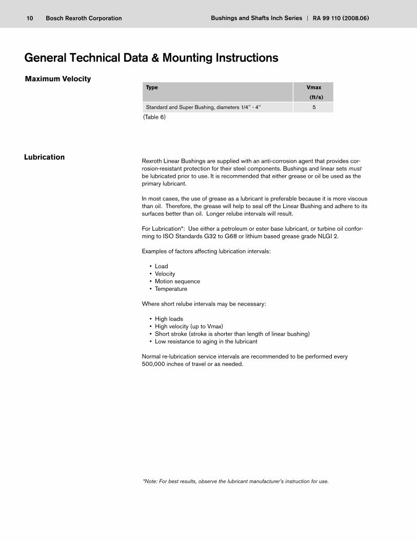
Type Vmax
(ft/s)
Standard and Super Bushing, diameters 1/4’’ - 4’’ 5
(Table 6)
Rexroth Linear Bushings are supplied with an anti-corrosion agent that provides cor-rosion-resistant protection for their steel components. Bushings and linear sets must be lubricated prior to use. It is recommended that either grease or oil be used as the primary lubricant.
In most cases, the use of grease as a lubricant is preferable because it is more viscous than oil. Therefore, the grease will help to seal off the Linear Bushing and adhere to its surfaces better than oil. Longer relube intervals will result.
For Lubrication*: Use either a petroleum or ester base lubricant, or turbine oil confor-ming to ISO Standards G32 to G68 or lithium based grease grade NLGI 2.
Examples of factors affecting lubrication intervals: • Load • Velocity • Motion sequence • Temperature
Where short relube intervals may be necessary:
• High loads • High velocity (up to Vmax) • Short stroke (stroke is shorter than length of linear bushing) • Low resistance to aging in the lubricant
Normal re-lubrication service intervals are recommended to be performed every 500,000 inches of travel or as needed.
*Note: For best results, observe the lubricant manufacturer’s instruction for use.
General Technical Data & Mounting Instructions
11Bosch Rexroth CoporationRA 99 110 (2008.06) Bushings and Shafts Inch Series
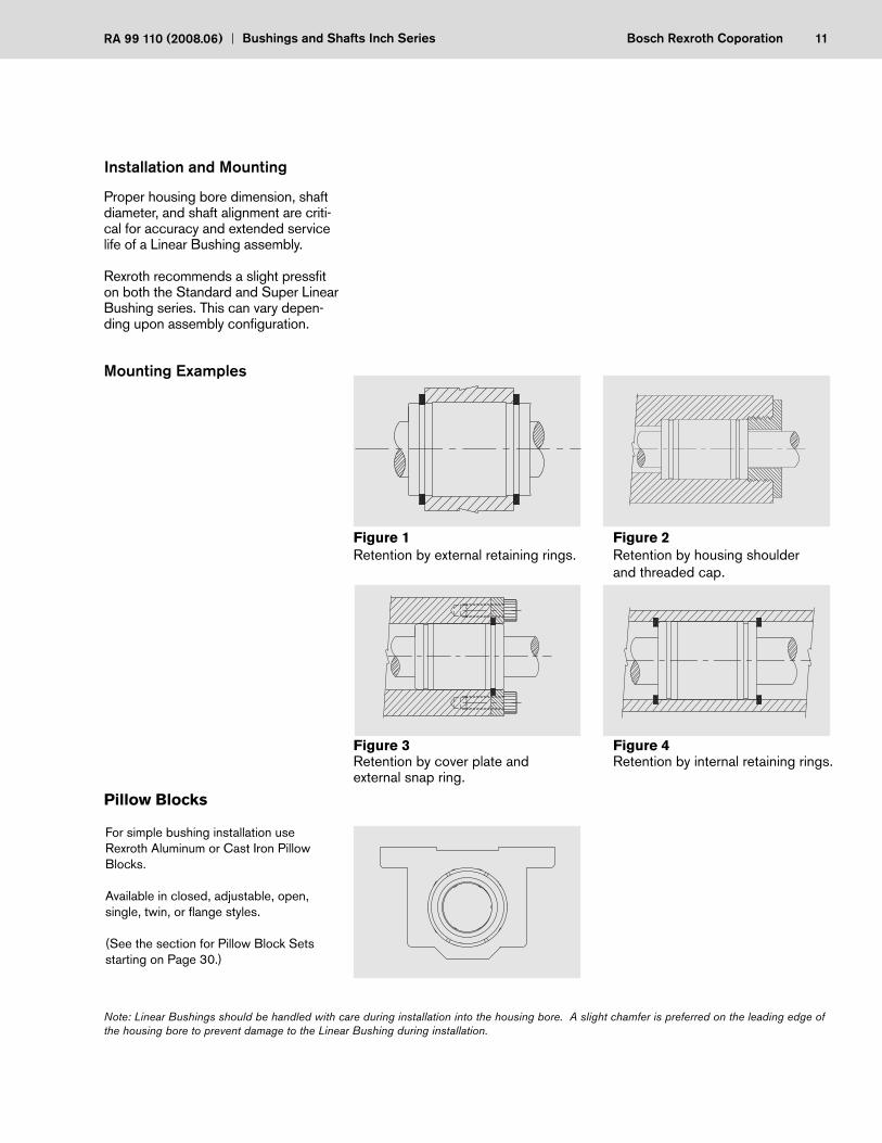
Figure 1 Figure 2Retention by external retaining rings. Retention by housing shoulder and threaded cap.
Figure 3 Figure 4Retention by cover plate and Retention by internal retaining rings.external snap ring.
Note: Linear Bushings should be handled with care during installation into the housing bore. A slight chamfer is preferred on the leading edge of the housing bore to prevent damage to the Linear Bushing during installation.
For simple bushing installation use Rexroth Aluminum or Cast Iron Pillow Blocks.
Available in closed, adjustable, open, single, twin, or fl ange styles.
(See the section for Pillow Block Sets starting on Page 30.)
Proper housing bore dimension, shaft diameter, and shaft alignment are criti-cal for accuracy and extended service life of a Linear Bushing assembly.
Rexroth recommends a slight pressfi t on both the Standard and Super Linear Bushing series. This can vary depen-ding upon assembly confi guration.
Mounting Examples
Pillow Blocks
12 Bosch Rexroth Corporation Bushings and Shafts Inch Series RA 99 110 (2008.06)
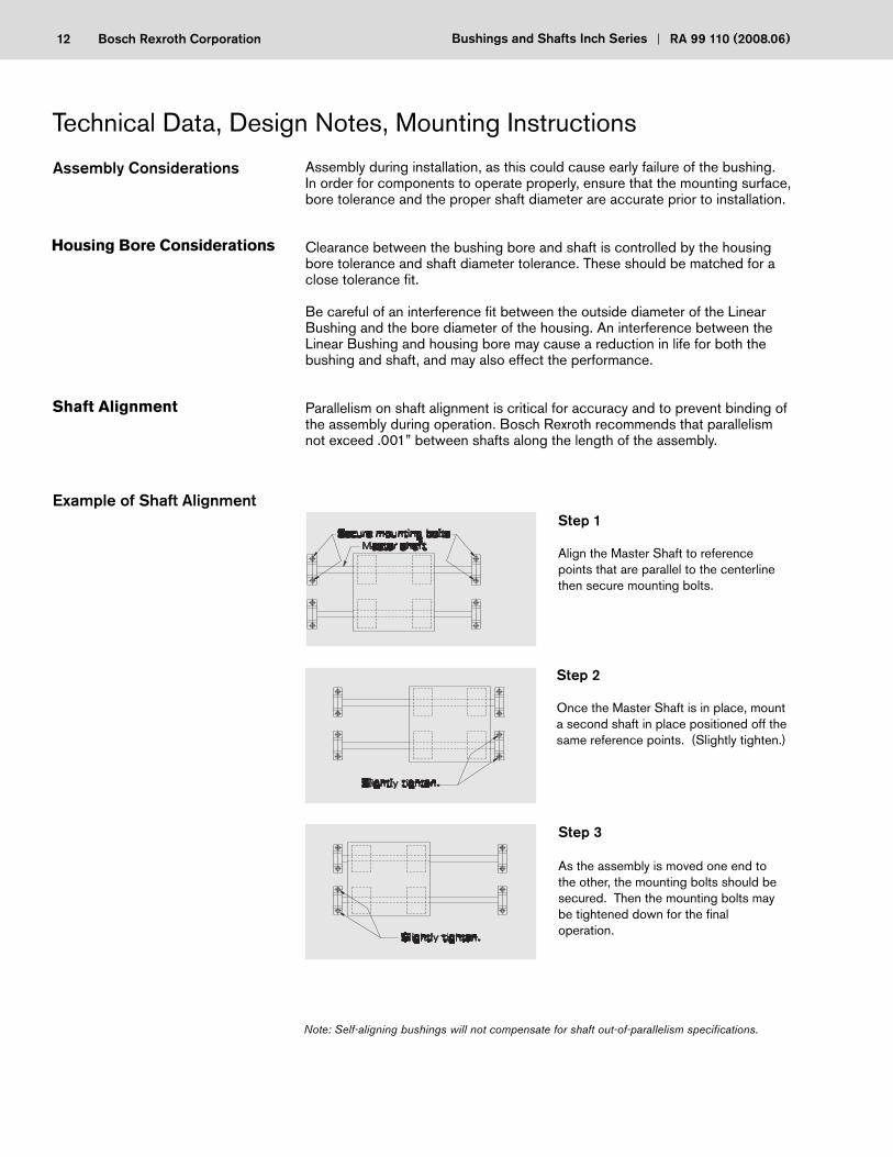
Note: Self-aligning bushings will not compensate for shaft out-of-parallelism specifi cations.
Assembly during installation, as this could cause early failure of the bushing.In order for components to operate properly, ensure that the mounting surface, bore tolerance and the proper shaft diameter are accurate prior to installation.
Clearance between the bushing bore and shaft is controlled by the housing bore tolerance and shaft diameter tolerance. These should be matched for a close tolerance fi t.
Be careful of an interference fi t between the outside diameter of the Linear Bushing and the bore diameter of the housing. An interference between the Linear Bushing and housing bore may cause a reduction in life for both the bushing and shaft, and may also effect the performance.
Parallelism on shaft alignment is critical for accuracy and to prevent binding of the assembly during operation. Bosch Rexroth recommends that parallelism not exceed .001” between shafts along the length of the assembly.
Step 1
Align the Master Shaft to reference points that are parallel to the centerline then secure mounting bolts.
13Bosch Rexroth CoporationRA 99 110 (2008.06) Bushings and Shafts Inch Series
To ensure the optimal performance of Rexroth Linear Bushings, precision shafts and housings are essential.
Appropriate clearance between the Rexroth Bushings and shaft is necessary for reliable performance. Inadequate radial clearance could cause premature failure as well as rough travel.
Dimensional tolerance, hardness and surface fi nish of the shaft greatly affect the operational performance of Linear Bushings.
The shaft must meet these specifi cations:
• Correct O.D. tolerance of the nominal shaft size on table 60, page 52.• Hardness of HRC 60-64. Hardness of less that HRC 60 will dramatically
reduce life and permissible load. Hardness over HRC 64 will accelerate ball wear.
• Depth must be a minimum of .04 inches.• Surface fi nish of 14 RA microinches (Ra 0.35) or less.
Proper selection and sizing of a housing bore will ensure consistent bushing performance. Rexroth Bushing housing bore recommendations offer slip-fi t with the bushing O.D. for improved service life.
See ‘Recommended Housing Bore’ section in the Dimensions and Specifi ca-tions pages for Linear Inch Bushings. ISO recommendations are indicated on Table 7, page 14.
Recommeded Tolerance for Housing Bore
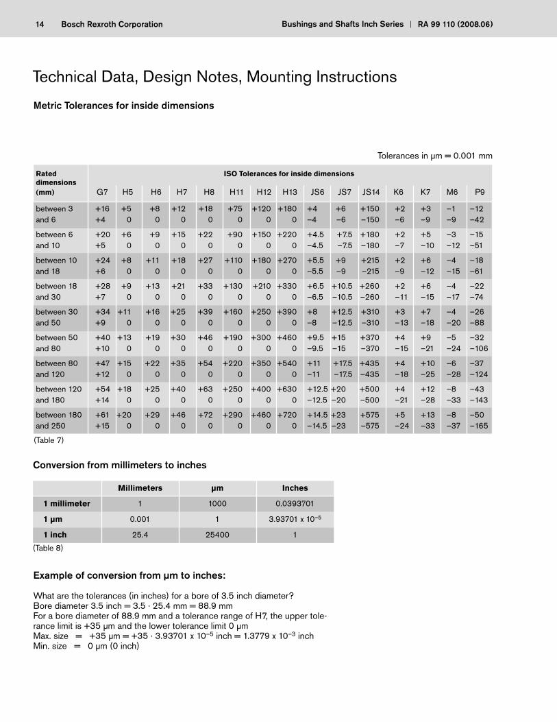
14 Bosch Rexroth Corporation Bushings and Shafts Inch Series RA 99 110 (2008.06)
Einheitsbohrung
Tolerances in μm = 0.001 mm
Millimeters μm Inches
1 millimeter 1 1000 0.0393701
1 μm 0.001 1 3.93701 x 10⁻⁵
1 inch 25.4 25400 1
Conversion from millimeters to inches
Example of conversion from μm to inches:
What are the tolerances (in inches) for a bore of 3.5 inch diameter?Bore diameter 3.5 inch = 3.5 · 25.4 mm = 88.9 mmFor a bore diameter of 88.9 mm and a tolerance range of H7, the upper tole-rance limit is +35 μm and the lower tolerance limit 0 μmMax. size = +35 μm = +35 · 3.93701 x 10–5 inch = 1.3779 x 10⁻³ inchMin. size = 0 μm (0 inch)
Rated ISO Tolerances for inside dimensionsdimensions (mm) G7 H5 H6 H7 H8 H11 H12 H13 JS6 JS7 JS14 K6 K7 M6 P9
between 3 +16 +5 +8 +12 +18 +75 +120 +180 +4 +6 +150 +2 +3 –1 –12and 6 +4 0 0 0 0 0 0 0 –4 –6 –150 –6 –9 –9 –42
between 6 +20 +6 +9 +15 +22 +90 +150 +220 +4.5 +7.5 +180 +2 +5 –3 –15and 10 +5 0 0 0 0 0 0 0 –4.5 –7.5 –180 –7 –10 –12 –51
between 10 +24 +8 +11 +18 +27 +110 +180 +270 +5.5 +9 +215 +2 +6 –4 –18and 18 +6 0 0 0 0 0 0 0 –5.5 –9 –215 –9 –12 –15 –61
between 18 +28 +9 +13 +21 +33 +130 +210 +330 +6.5 +10.5 +260 +2 +6 –4 –22and 30 +7 0 0 0 0 0 0 0 –6.5 –10.5 –260 –11 –15 –17 –74
between 30 +34 +11 +16 +25 +39 +160 +250 +390 +8 +12.5 +310 +3 +7 –4 –26and 50 +9 0 0 0 0 0 0 0 –8 –12.5 –310 –13 –18 –20 –88
between 50 +40 +13 +19 +30 +46 +190 +300 +460 +9.5 +15 +370 +4 +9 –5 –32and 80 +10 0 0 0 0 0 0 0 –9.5 –15 –370 –15 –21 –24 –106
between 80 +47 +15 +22 +35 +54 +220 +350 +540 +11 +17.5 +435 +4 +10 –6 –37and 120 +12 0 0 0 0 0 0 0 –11 –17.5 –435 –18 –25 –28 –124
between 120 +54 +18 +25 +40 +63 +250 +400 +630 +12.5 +20 +500 +4 +12 –8 –43and 180 +14 0 0 0 0 0 0 0 –12.5 –20 –500 –21 –28 –33 –143
between 180 +61 +20 +29 +46 +72 +290 +460 +720 +14.5 +23 +575 +5 +13 –8 –50and 250 +15 0 0 0 0 0 0 0 –14.5 –23 –575 –24 –33 –37 –165
(Table 7)
(Table 8)
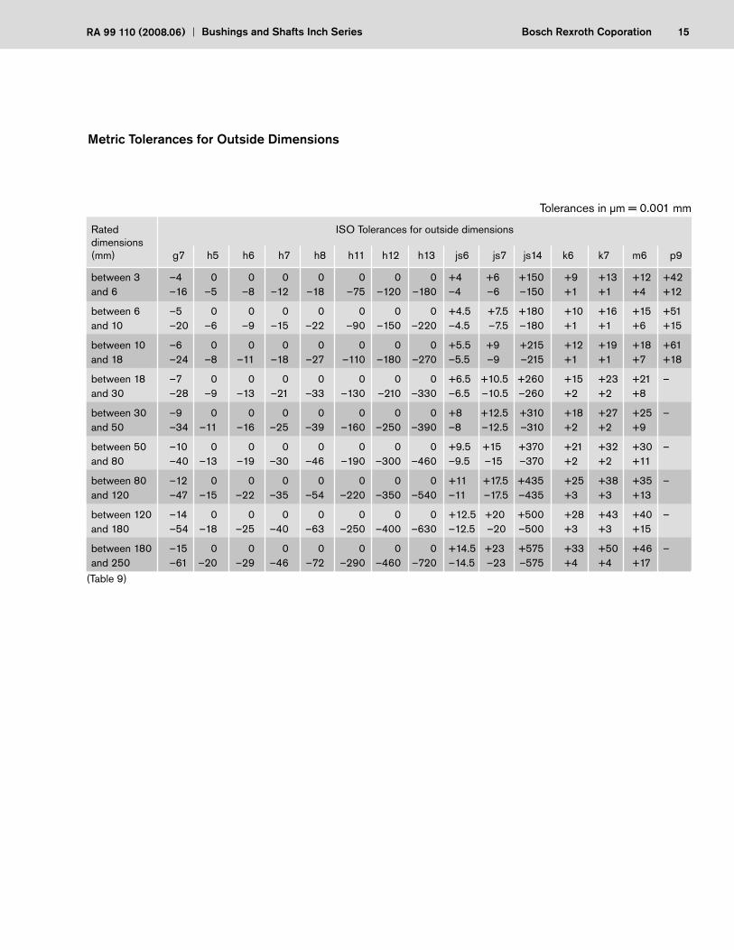
15Bosch Rexroth CoporationRA 99 110 (2008.06) Bushings and Shafts Inch Series
Einheitswelle
Tolerances in μm = 0.001 mm
Rated ISO Tolerances for outside dimensionsdimensions (mm) g7 h5 h6 h7 h8 h11 h12 h13 js6 js7 js14 k6 k7 m6 p9
between 3 –4 0 0 0 0 0 0 0 +4 +6 +150 +9 +13 +12 +42and 6 –16 –5 –8 –12 –18 –75 –120 –180 –4 –6 –150 +1 +1 +4 +12
between 6 –5 0 0 0 0 0 0 0 +4.5 +7.5 +180 +10 +16 +15 +51and 10 –20 –6 –9 –15 –22 –90 –150 –220 –4.5 –7.5 –180 +1 +1 +6 +15
between 10 –6 0 0 0 0 0 0 0 +5.5 +9 +215 +12 +19 +18 +61and 18 –24 –8 –11 –18 –27 –110 –180 –270 –5.5 –9 –215 +1 +1 +7 +18
between 18 –7 0 0 0 0 0 0 0 +6.5 +10.5 +260 +15 +23 +21 –and 30 –28 –9 –13 –21 –33 –130 –210 –330 –6.5 –10.5 –260 +2 +2 +8
between 30 –9 0 0 0 0 0 0 0 +8 +12.5 +310 +18 +27 +25 –and 50 –34 –11 –16 –25 –39 –160 –250 –390 –8 –12.5 –310 +2 +2 +9
between 50 –10 0 0 0 0 0 0 0 +9.5 +15 +370 +21 +32 +30 –and 80 –40 –13 –19 –30 –46 –190 –300 –460 –9.5 –15 –370 +2 +2 +11
between 80 –12 0 0 0 0 0 0 0 +11 +17.5 +435 +25 +38 +35 –and 120 –47 –15 –22 –35 –54 –220 –350 –540 –11 –17.5 –435 +3 +3 +13
between 120 –14 0 0 0 0 0 0 0 +12.5 +20 +500 +28 +43 +40 –and 180 –54 –18 –25 –40 –63 –250 –400 –630 –12.5 –20 –500 +3 +3 +15
between 180 –15 0 0 0 0 0 0 0 +14.5 +23 +575 +33 +50 +46 –and 250 –61 –20 –29 –46 –72 –290 –460 –720 –14.5 –23 –575 +4 +4 +17
(Table 9)
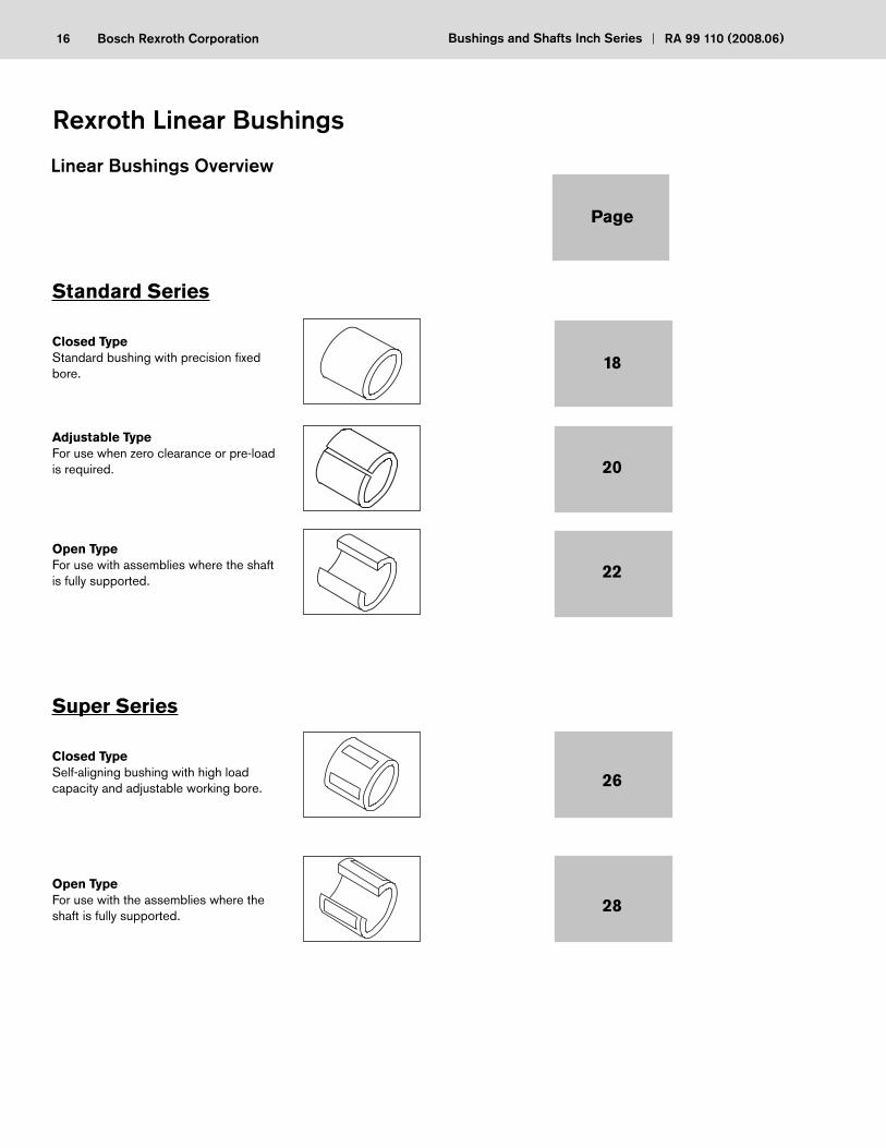
16 Bosch Rexroth Corporation Bushings and Shafts Inch Series RA 99 110 (2008.06)
Standard Series
Closed TypeStandard bushing with precision fi xed bore.
Adjustable TypeFor use when zero clearance or pre-load is required.
Open TypeFor use with assemblies where the shaft is fully supported.
Super Series
Closed TypeSelf-aligning bushing with high load capacity and adjustable working bore.
Open TypeFor use with the assemblies where the shaft is fully supported.
Page
18
20
22
26
28
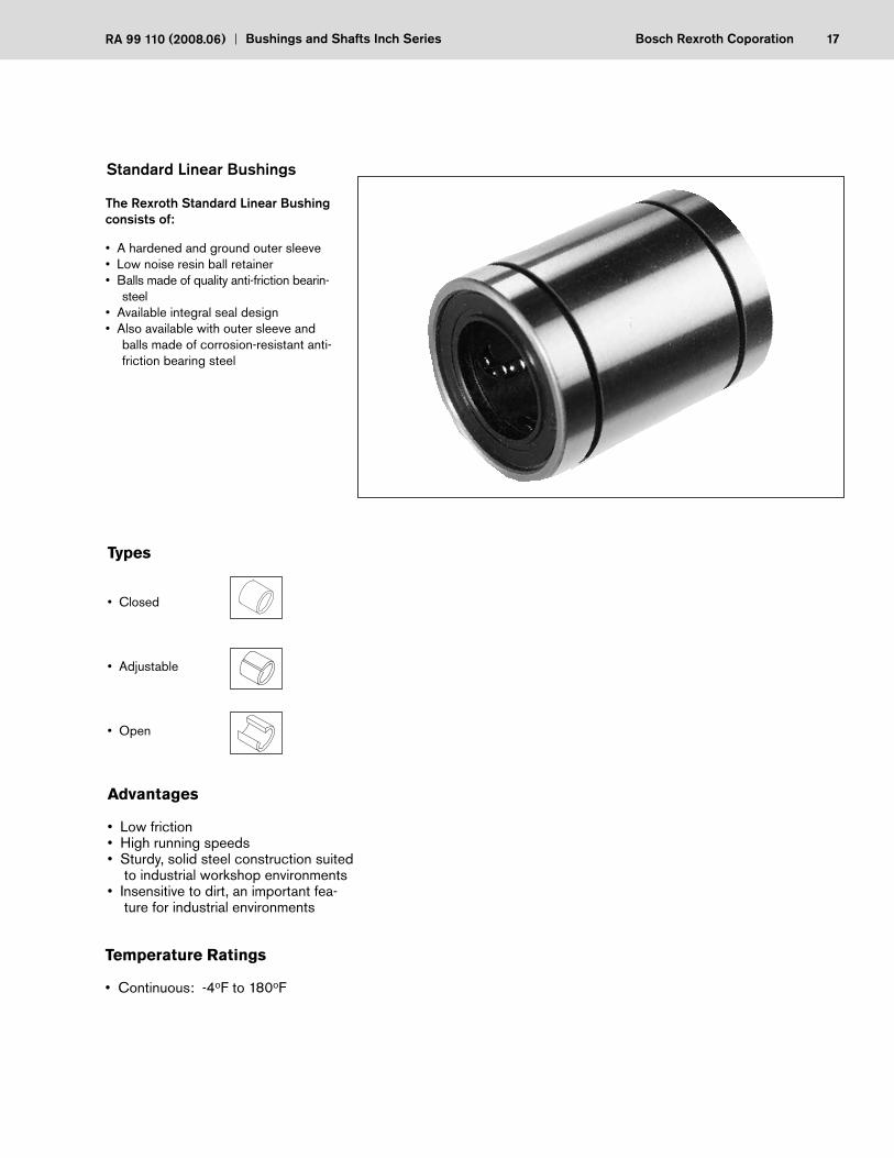
17Bosch Rexroth CoporationRA 99 110 (2008.06) Bushings and Shafts Inch Series
Standard Linear Bushings
Types
• Closed
• Adjustable
• Open
Advantages
• Low friction• High running speeds• Sturdy, solid steel construction suited
to industrial workshop environments• Insensitive to dirt, an important fea-
ture for industrial environments
Temperature Ratings
The Rexroth Standard Linear Bushing consists of:
• A hardened and ground outer sleeve• Low noise resin ball retainer• Balls made of quality anti-friction bearin-
steel• Available integral seal design• Also available with outer sleeve and
balls made of corrosion-resistant anti-friction bearing steel
• Continuous: -4oF to 180oF
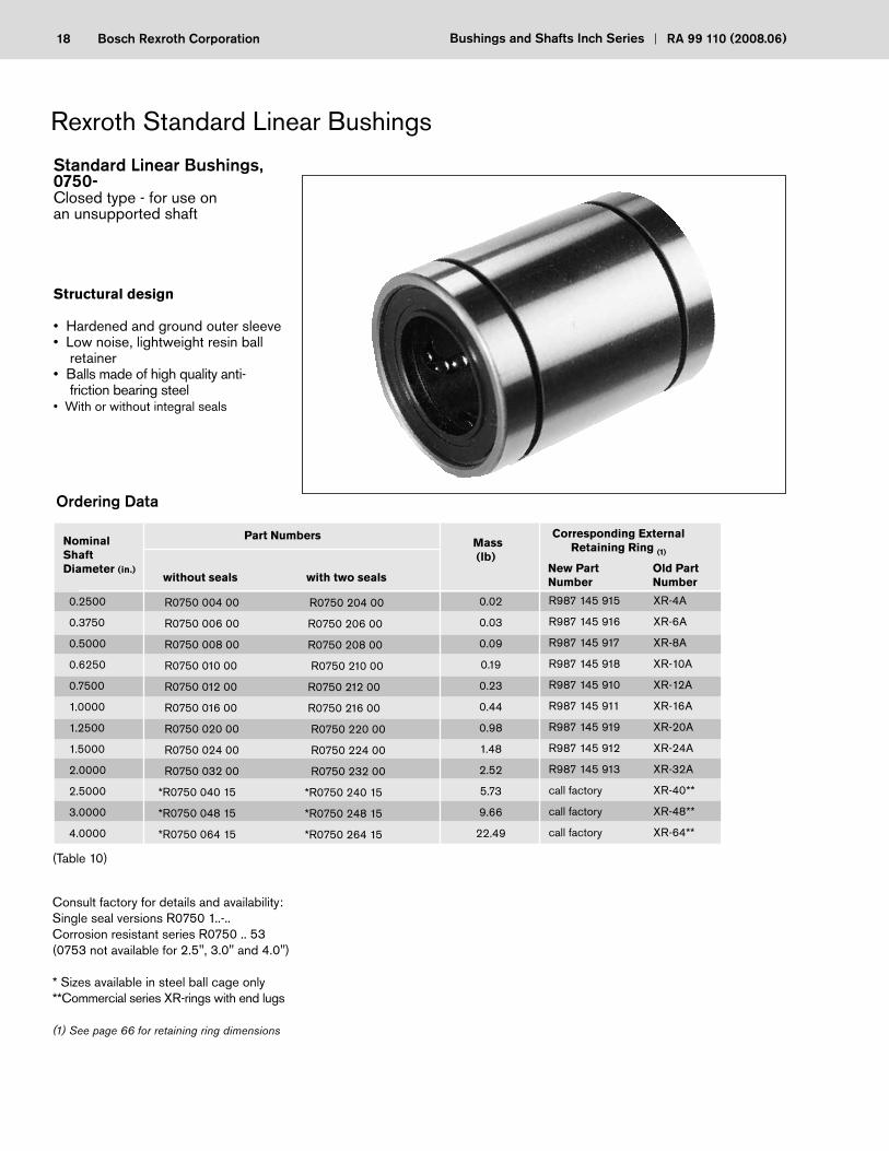
18 Bosch Rexroth Corporation Bushings and Shafts Inch Series RA 99 110 (2008.06)
Standard Linear Bushings, 0750-Closed type - for use on an unsupported shaft
Structural design
• Hardened and ground outer sleeve• Low noise, lightweight resin ball
retainer• Balls made of high quality anti- friction bearing steel• With or without integral seals
(Table 10)
Consult factory for details and availability:Single seal versions R0750 1..-..Corrosion resistant series R0750 .. 53(0753 not available for 2.5", 3.0" and 4.0")
* Sizes available in steel ball cage only**Commercial series XR-rings with end lugs
(1) See page 66 for retaining ring dimensions
NominalShaftDiameter (in.)
without seals with two seals
Part NumbersMass (lb)
Corresponding External Retaining Ring (1)
Ordering Data
0.2500
0.3750
0.5000
0.6250
0.7500
1.0000
1.2500
1.5000
2.0000
2.5000
3.0000
4.0000
R0750 004 00
R0750 006 00
R0750 008 00
R0750 010 00
R0750 012 00
R0750 016 00
R0750 020 00
R0750 024 00
R0750 032 00
*R0750 040 15
*R0750 048 15
*R0750 064 15
R0750 204 00
R0750 206 00
R0750 208 00
R0750 210 00
R0750 212 00
R0750 216 00
R0750 220 00
R0750 224 00
R0750 232 00
*R0750 240 15
*R0750 248 15
*R0750 264 15
0.02
0.03
0.09
0.19
0.23
0.44
0.98
1.48
2.52
5.73
9.66
22.49
R987 145 915 XR-4A
R987 145 916 XR-6A
R987 145 917 XR-8A
R987 145 918 XR-10A
R987 145 910 XR-12A
R987 145 911 XR-16A
R987 145 919 XR-20A
R987 145 912 XR-24A
R987 145 913 XR-32A
call factory XR-40**
call factory XR-48**
call factory XR-64**
New Part Old Part Number Number
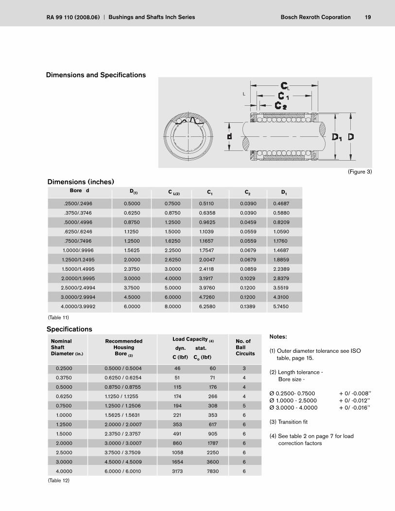
19Bosch Rexroth CoporationRA 99 110 (2008.06) Bushings and Shafts Inch Series
L
Bore d D(1) C L(2) C1 C2 D1
(Table 11)
NominalShaftDiameter (in.)
RecommendedHousingBore (3)
Load Capacity (4)
dyn. stat.
C (lbf) Co (lbf)
No. ofBall Circuits
Specifi cations
(Table 12)
Notes:
(1) Outer diameter tolerance see ISO table, page 15.
(2) Length tolerance - Bore size -
Ø 0.2500- 0.7500 + 0/ -0.008’’Ø 1.0000 - 2.5000 + 0/ -0.012’’Ø 3.0000 - 4.0000 + 0/ -0.016’’
(3) Transition fi t
(4) See table 2 on page 7 for load correction factors
.2500/.2496
.3750/.3746
.5000/.4996
.6250/.6246
.7500/.7496
1.0000/.9996
1.2500/1.2495
1.5000/1.4995
2.0000/1.9995
2.5000/2.4994
3.0000/2.9994
4.0000/3.9992
0.5000
0.6250
0.8750
1.1250
1.2500
1.5625
2.0000
2.3750
3.0000
3.7500
4.5000
6.0000
0.7500
0.8750
1.2500
1.5000
1.6250
2.2500
2.6250
3.0000
4.0000
5.0000
6.0000
8.0000
0.5110
0.6358
0.9625
1.1039
1.1657
1.7547
2.0047
2.4118
3.1917
3.9760
4.7260
6.2580
0.0390
0.0390
0.0459
0.0559
0.0559
0.0679
0.0679
0.0859
0.1029
0.1200
0.1200
0.1389
0.4687
0.5880
0.8209
1.0590
1.1760
1.4687
1.8859
2.2389
2.8379
3.5519
4.3100
5.7450
0.2500
0.3750
0.5000
0.6250
0.7500
1.0000
1.2500
1.5000
2.0000
2.5000
3.0000
4.0000
0.5000 / 0.5004
0.6250 / 0.6254
0.8750 / 0.8755
1.1250 / 1.1255
1.2500 / 1.2506
1.5625 / 1.5631
2.0000 / 2.0007
2.3750 / 2.3757
3.0000 / 3.0007
3.7500 / 3.7509
4.5000 / 4.5009
6.0000 / 6.0010
46
51
115
174
194
221
353
491
860
1058
1654
3173
60
71
176
266
308
353
617
905
1787
2250
3600
7830
3
4
4
4
5
6
6
6
6
6
6
6
(Figure 3)
L
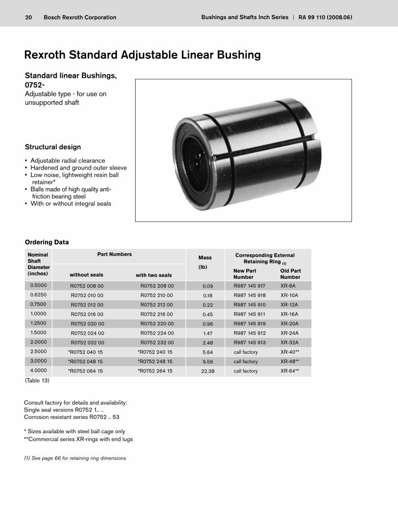
20 Bosch Rexroth Corporation Bushings and Shafts Inch Series RA 99 110 (2008.06)
Standard linear Bushings, 0752-Adjustable type - for use on unsupported shaft
Structural design
• Adjustable radial clearance• Hardened and ground outer sleeve• Low noise, lightweight resin ball
retainer*• Balls made of high quality anti- friction bearing steel• With or without integral seals
Rexroth Standard Adjustable Linear Bushing
NominalShaftDiameter (inches) without seals with two seals
Part NumbersMass
(lb)
Ordering Data
(Table 13)
Consult factory for details and availability:Single seal versions R0752 1.. ..Corrosion resistant series R0752 .. 53
* Sizes available with steel ball cage only**Commercial series XR-rings with end lugs
(1) See page 66 for retaining ring dimensions
0.5000
0.6250
0.7500
1.0000
1.2500
1.5000
2.0000
2.5000
3.0000
4.0000
R0752 008 00
R0752 010 00
R0752 012 00
R0752 016 00
R0752 020 00
R0752 024 00
R0752 032 00
*R0752 040 15
*R0752 048 15
*R0752 064 15
R0752 208 00
R0752 210 00
R0752 212 00
R0752 216 00
R0752 220 00
R0752 224 00
R0752 232 00
*R0752 240 15
*R0752 248 15
*R0752 264 15
0.09
0.18
0.22
0.45
0.96
1.47
2.48
5.64
9.59
22.38
Corresponding External Retaining Ring (1)
R987 145 917 XR-8A
R987 145 918 XR-10A
R987 145 910 XR-12A
R987 145 911 XR-16A
R987 145 919 XR-20A
R987 145 912 XR-24A
R987 145 913 XR-32A
call factory XR-40**
call factory XR-48**
call factory XR-64**
New Part Old Part Number Number
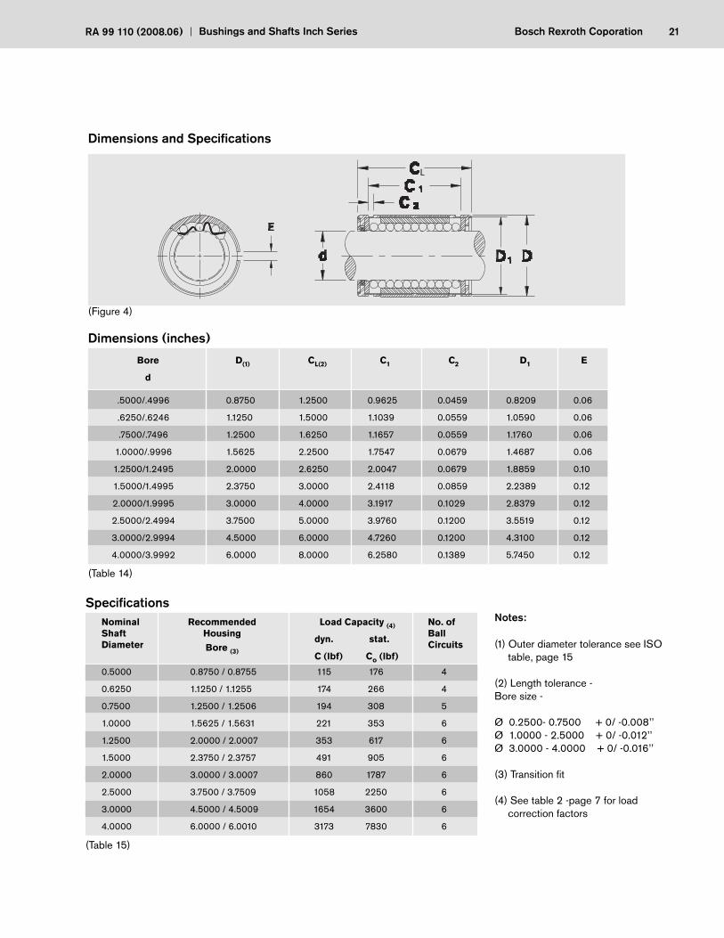
21Bosch Rexroth CoporationRA 99 110 (2008.06) Bushings and Shafts Inch Series
Dimensions and Specifi cations
(Table 14)
Bore
d
D(1) CL(2) C1 C2 D1
Dimensions (inches)
E
NominalShaftDiameter
RecommendedHousing
Bore (3)
Load Capacity (4)
dyn. stat.
C (lbf) Co (lbf)
No. ofBallCircuits
Specifi cations
(Table 15)
Notes:
(1) Outer diameter tolerance see ISO table, page 15
(2) Length tolerance - Bore size -
Ø 0.2500- 0.7500 + 0/ -0.008’’Ø 1.0000 - 2.5000 + 0/ -0.012’’Ø 3.0000 - 4.0000 + 0/ -0.016’’
(3) Transition fi t
(4) See table 2 -page 7 for load correction factors
.5000/.4996
.6250/.6246
.7500/.7496
1.0000/.9996
1.2500/1.2495
1.5000/1.4995
2.0000/1.9995
2.5000/2.4994
3.0000/2.9994
4.0000/3.9992
0.8750
1.1250
1.2500
1.5625
2.0000
2.3750
3.0000
3.7500
4.5000
6.0000
1.2500
1.5000
1.6250
2.2500
2.6250
3.0000
4.0000
5.0000
6.0000
8.0000
0.9625
1.1039
1.1657
1.7547
2.0047
2.4118
3.1917
3.9760
4.7260
6.2580
0.0459
0.0559
0.0559
0.0679
0.0679
0.0859
0.1029
0.1200
0.1200
0.1389
0.8209
1.0590
1.1760
1.4687
1.8859
2.2389
2.8379
3.5519
4.3100
5.7450
0.06
0.06
0.06
0.06
0.10
0.12
0.12
0.12
0.12
0.12
0.5000
0.6250
0.7500
1.0000
1.2500
1.5000
2.0000
2.5000
3.0000
4.0000
0.8750 / 0.8755
1.1250 / 1.1255
1.2500 / 1.2506
1.5625 / 1.5631
2.0000 / 2.0007
2.3750 / 2.3757
3.0000 / 3.0007
3.7500 / 3.7509
4.5000 / 4.5009
6.0000 / 6.0010
115
174
194
221
353
491
860
1058
1654
3173
176
266
308
353
617
905
1787
2250
3600
7830
4
4
5
6
6
6
6
6
6
6
(Figure 4)
L

22 Bosch Rexroth Corporation Bushings and Shafts Inch Series RA 99 110 (2008.06)
Consult factory for details and availability:Single seal versions R0750 1.. ..Corrosion resistant series R0750 .. 53(0753 not available for 2.5", 3.0" and 4.0")
* Sizes available in steel ball cage only**Commercial series XR-rings with end lugs
(1) See page 66 for retaining ring dimensions
Standard Linear Bushing, 0753-Open type - for use on a supported shaft
Structural design
• Hardened and ground outer sleeve• Low noise,lightweight resin ball
retainer* • Balls made of high quality
anti-friction bearing steel• With or without integral seals
NominalShaftDiameter without seals with two seals
Part Numbers Mass (lb)
Ordering Data
(Table 16)
0.5000
0.6250
0.7500
1.0000
1.2500
1.5000
2.0000
2.5000
3.0000
4.0000
R0753 008 00
R0753 010 00
R0753 012 00
R0753 016 00
R0753 020 00
R0753 024 00
R0753 032 00
* R0753 040 15
* R0753 048 15
* R0753 064 15
R0753 208 00
R0753 210 00
R0753 212 00
R0753 216 00
R0753 220 00
R0753 224 00
R0753 232 00
* R0753 240 15
* R0753 248 15
* R0753 264 15
0.07
0.14
0.19
0.42
0.86
1.34
2.47
4.92
8.27
19.27
Corresponding External Retaining Ring (1)
R987 145 917 XR-8A
R987 145 918 XR-10A
R987 145 910 XR-12A
R987 145 911 XR-16A
R987 145 919 XR-20A
R987 145 912 XR-24A
R987 145 913 XR-32A
n/a
n/a
n/a
New Part Old Part Number Number
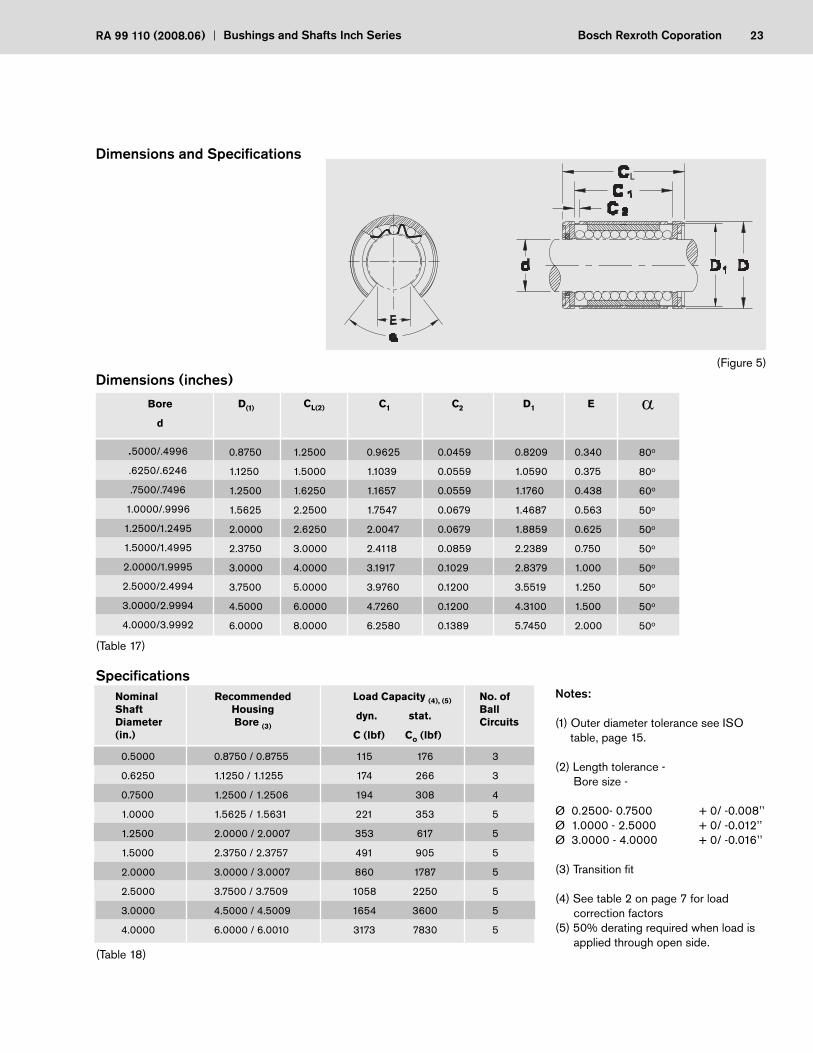
23Bosch Rexroth CoporationRA 99 110 (2008.06) Bushings and Shafts Inch Series
(Table 17)
Bore
d
CL(2) C1 C2 D1 E
NominalShaftDiameter (in.)
RecommendedHousingBore (3)
Load Capacity (4), (5)
dyn. stat.
C (lbf) Co (lbf)
No. ofBallCircuits
Specifi cations
(Table 18)
D(1)
.5000/.4996
.6250/.6246
.7500/.7496
1.0000/.9996
1.2500/1.2495
1.5000/1.4995
2.0000/1.9995
2.5000/2.4994
3.0000/2.9994
4.0000/3.9992
0.8750
1.1250
1.2500
1.5625
2.0000
2.3750
3.0000
3.7500
4.5000
6.0000
1.2500
1.5000
1.6250
2.2500
2.6250
3.0000
4.0000
5.0000
6.0000
8.0000
0.9625
1.1039
1.1657
1.7547
2.0047
2.4118
3.1917
3.9760
4.7260
6.2580
0.0459
0.0559
0.0559
0.0679
0.0679
0.0859
0.1029
0.1200
0.1200
0.1389
0.340
0.375
0.438
0.563
0.625
0.750
1.000
1.250
1.500
2.000
80o
80o
60o
50o
50o
50o
50o
50o
50o
50o
0.8209
1.0590
1.1760
1.4687
1.8859
2.2389
2.8379
3.5519
4.3100
5.7450
0.5000
0.6250
0.7500
1.0000
1.2500
1.5000
2.0000
2.5000
3.0000
4.0000
0.8750 / 0.8755
1.1250 / 1.1255
1.2500 / 1.2506
1.5625 / 1.5631
2.0000 / 2.0007
2.3750 / 2.3757
3.0000 / 3.0007
3.7500 / 3.7509
4.5000 / 4.5009
6.0000 / 6.0010
115
174
194
221
353
491
860
1058
1654
3173
176
266
308
353
617
905
1787
2250
3600
7830
3
3
4
5
5
5
5
5
5
5
(Figure 5)
Notes:
(1) Outer diameter tolerance see ISO table, page 15.
(2) Length tolerance - Bore size -
Ø 0.2500- 0.7500 + 0/ -0.008’’Ø 1.0000 - 2.5000 + 0/ -0.012’’Ø 3.0000 - 4.0000 + 0/ -0.016’’
(3) Transition fi t
(4) See table 2 on page 7 for load correction factors(5) 50% derating required when load is
applied through open side.
L
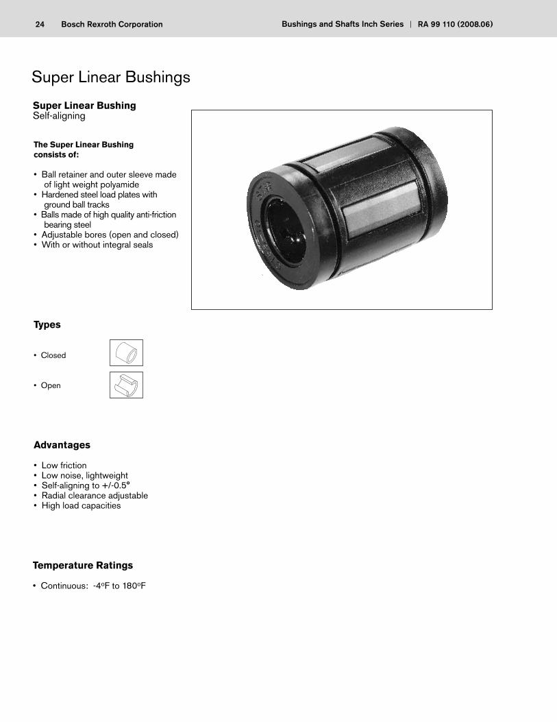
24 Bosch Rexroth Corporation Bushings and Shafts Inch Series RA 99 110 (2008.06)
The Super Linear Bushing consists of:
• Ball retainer and outer sleeve made of light weight polyamide
• Hardened steel load plates with ground ball tracks
• Balls made of high quality anti-friction bearing steel
• Adjustable bores (open and closed)• With or without integral seals
Types
• Closed
• Open
Advantages
• Low friction• Low noise, lightweight• Self-aligning to +/-0.5°• Radial clearance adjustable• High load capacities
Temperature Ratings
• Continuous: -4oF to 180oF
25Bosch Rexroth CoporationRA 99 110 (2008.06) Bushings and Shafts Inch Series
Rexroth’s Super Linear Bushings compensate for alignment errors of up to one degree without reduction of load capacity.
The steel load plates are designed with the central portion of the plate slightly larger than the ends. This design serves as a fulcrum point to allow for each load plate to compensate for minor errors in alignment between shaft and housing bore caused by inaccurate machining or shaft defl ection.
Much smoother operation, higher load capacity and substantially longer travel life than conventional Linear Bushings.
Each load plate has a ground surface raceway providing low friction and high load.
With its high load capacity and ability to compensate for inaccurate machi-ne tolerances, the Super Linear Bushing allows for use of smaller compo-nents in the application. Shaft, bushing, and housing can be reduced, thereby saving money and design consideration of all the elements.
The Super Linear Bushing provides up to three times the load capacity and 27 times the travel life of Standard Linear Bushings, due to its special load plate design.
Note: Contact the factory for details on the Rexroth Super Linear Bushing design and rating information
Results
Ground Ball Tracks
Cost-effective Design
Load Capacity and Travel Life
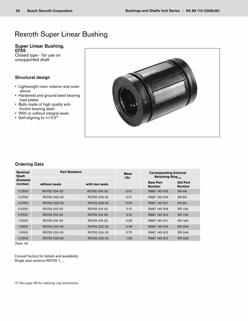
26 Bosch Rexroth Corporation Bushings and Shafts Inch Series RA 99 110 (2008.06)
Consult factory for details and availability:Single seal versions R0755 1.. ..
(1) See page 66 for retaining ring dimensions
Super Linear Bushing, 0755Closed type - for use on unsupported shaft
Structural design
• Lightweight resin retainer and outer sleeve
• Hardened and ground steel bearing load plates
• Balls made of high quality anti- friction bearing steel• With or without integral seals• Self-aligning to +/-0.5°
NominalShaftDiameter(inches) without seals with two seals
Part Numbers Mass (lb)
0.2500
0.3750
0.5000
0.6250
0.7500
1.0000
1.2500
1.5000
2.0000
R0755 004 00
R0755 006 00
R0755 008 00
R0755 010 00
R0755 012 00
R0755 016 00
R0755 020 00
R0755 024 00
R0755 032-00
R0755 204 00
R0755 206 00
R0755 208 00
R0755 210 00
R0755 212 00
R0755 216 00
R0755 220 00
R0755 224 00
R0755 232 00
0.01
0.01
0.04
0.10
0.12
0.26
0.49
0.75
1.39
(Table 16)
Corresponding External Retaining Ring (1)
R987 145 915 XR-4A
R987 145 916 XR-6A
R987 145 917 XR-8A
R987 145 918 XR-10A
R987 145 910 XR-12A
R987 145 911 XR-16A
R987 145 919 XR-20A
R987 145 912 XR-24A
R987 145 913 XR-32A
New Part Old Part Number Number
27Bosch Rexroth CoporationRA 99 110 (2008.06) Bushings and Shafts Inch Series
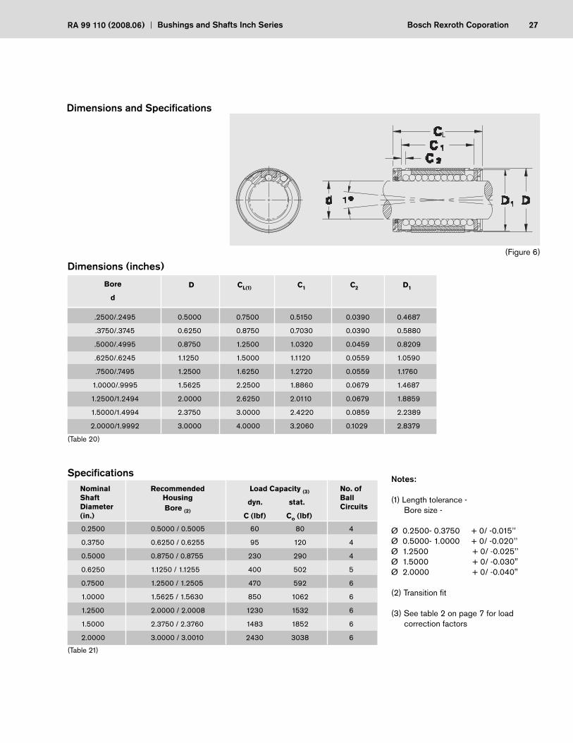
(Figure 6)
Notes:
(1) Length tolerance - Bore size -
Ø 0.2500- 0.3750 + 0/ -0.015’’Ø 0.5000- 1.0000 + 0/ -0.020’’Ø 1.2500 + 0/ -0.025’’Ø 1.5000 + 0/ -0.030"Ø 2.0000 + 0/ -0.040"
(2) Transition fi t
(3) See table 2 on page 7 for load correction factors
Bore
d
D CL(1) C1 C2 D1
(Table 20)
NominalShaftDiameter (in.)
RecommendedHousingBore (2)
Load Capacity (3)
dyn. stat.
C (lbf) Co (lbf)
No. ofBallCircuits
(Table 21)
.2500/.2495
.3750/.3745
.5000/.4995
.6250/.6245
.7500/.7495
1.0000/.9995
1.2500/1.2494
1.5000/1.4994
2.0000/1.9992
0.5000
0.6250
0.8750
1.1250
1.2500
1.5625
2.0000
2.3750
3.0000
0.7500
0.8750
1.2500
1.5000
1.6250
2.2500
2.6250
3.0000
4.0000
0.5150
0.7030
1.0320
1.1120
1.2720
1.8860
2.0110
2.4220
3.2060
0.0390
0.0390
0.0459
0.0559
0.0559
0.0679
0.0679
0.0859
0.1029
0.4687
0.5880
0.8209
1.0590
1.1760
1.4687
1.8859
2.2389
2.8379
0.5000 / 0.5005
0.6250 / 0.6255
0.8750 / 0.8755
1.1250 / 1.1255
1.2500 / 1.2505
1.5625 / 1.5630
2.0000 / 2.0008
2.3750 / 2.3760
3.0000 / 3.0010
60
95
230
400
470
850
1230
1483
2430
80
120
290
502
592
1062
1532
1852
3038
4
4
4
5
6
6
6
6
6
0.2500
0.3750
0.5000
0.6250
0.7500
1.0000
1.2500
1.5000
2.0000
L
28 Bosch Rexroth Corporation Bushings and Shafts Inch Series RA 99 110 (2008.06)
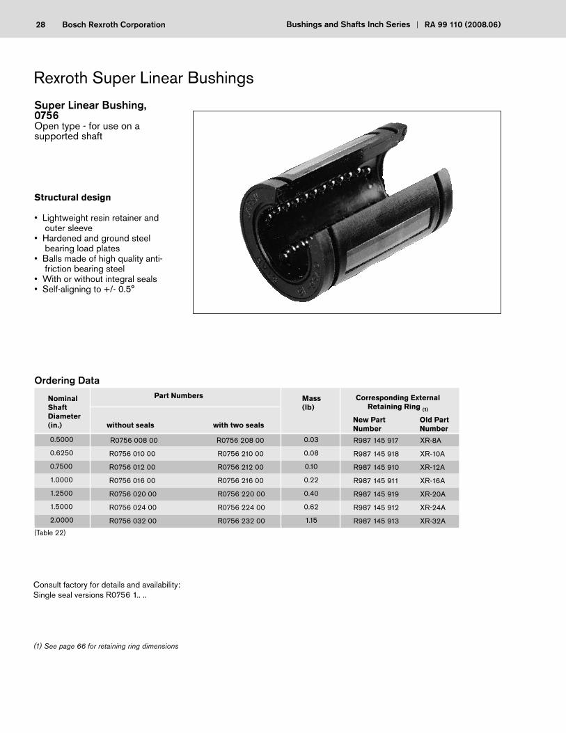
Super Linear Bushing, 0756Open type - for use on a supported shaft
Structural design
• Lightweight resin retainer and outer sleeve
• Hardened and ground steel bearing load plates
• Balls made of high quality anti- friction bearing steel
• With or without integral seals• Self-aligning to +/- 0.5°
NominalShaftDiameter(in.) without seals with two seals
Part Numbers Mass(lb)
Ordering Data
(Table 22)
0.5000
0.6250
0.7500
1.0000
1.2500
1.5000
2.0000
R0756 008 00
R0756 010 00
R0756 012 00
R0756 016 00
R0756 020 00
R0756 024 00
R0756 032 00
R0756 208 00
R0756 210 00
R0756 212 00
R0756 216 00
R0756 220 00
R0756 224 00
R0756 232 00
0.03
0.08
0.10
0.22
0.40
0.62
1.15
Consult factory for details and availability:Single seal versions R0756 1.. ..
(1) See page 66 for retaining ring dimensions
Corresponding External Retaining Ring (1)
R987 145 917 XR-8A
R987 145 918 XR-10A
R987 145 910 XR-12A
R987 145 911 XR-16A
R987 145 919 XR-20A
R987 145 912 XR-24A
R987 145 913 XR-32A
New Part Old Part Number Number
29Bosch Rexroth CoporationRA 99 110 (2008.06) Bushings and Shafts Inch Series
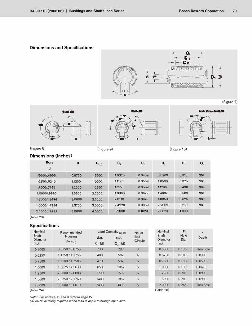
(Table 23)
Bore
d
CL(1) C1 C2 D1 ED
NominalShaftDiameter(in.)
RecommendedHousingBore (2)
Load Capacity (3), (4)
dyn. stat.
C (lbf) Co (lbf)
No. ofBallCircuits
(Table 24)
Nominal Shaft Diameter(in.)
FHoleDia.
J
Depth
(Table 25)
Note: For notes 1, 2, and 3 refer to page 27(4) 50 % derating required when load is applied through open side.
.5000/.4995
.6250/.6245
.7500/.7495
1.0000/.9995
1.2500/1.2494
1.5000/1.4994
2.0000/1.9992
0.8750
1.1250
1.2500
1.5625
2.0000
2.3750
3.0000
1.2500
1.5000
1.6250
2.2500
2.6250
3.0000
4.0000
1.0320
1.1120
1.2720
1.8860
2.0110
2.4220
3.2060
0.0459
0.0559
0.0559
0.0679
0.0679
0.0859
0.1029
0.8209
1.0590
1.1760
1.4687
1.8859
2.2389
2.8379
0.313
0.375
0.438
0.563
0.625
0.750
1.000
0.5000
0.6250
0.7500
1.0000
1.2500
1.5000
2.0000
0.8750 / 0.8755
1.1250 / 1.1255
1.2500 / 1.2505
1.5625 / 1.5630
2.0000 / 2.0008
2.3750 / 2.3760
3.0000 / 3.0010
230
400
470
850
1230
1483
2430
290
502
592
1062
1532
1852
3038
3
4
5
5
5
5
5
0.5000
0.6250
0.7500
1.0000
1.2500
1.5000
2.0000
0.136
0.105
0.136
0.136
0.201
0.201
0.265
(Figure 7)
Thru hole
0.0390
0.0590
0.0470
0.0900
0.0900
Thru hole
L
30o
30o
30o
30o
30o
30o
(Figure 8) (Figure 9) (Figure 10)

30 Bosch Rexroth Corporation Bushings and Shafts Inch Series RA 99 110 (2008.06)
Overview
Cast Iron Series
Closed TypeStandard type with fi xed bore and self-aligning spherical sleeve.
Adjustable TypeFor use when zero clearance or preload is required.
Open TypeFor use with long guideways when the shaft is fully supported.
44
46
48
Single Sets Twin Sets
Aluminum Series
Closed TypeStandard type with self-aligning insert used for high load.
Adjustable TypeFor use when zero clearance or pre-load is required.
Open TypeFor use with long guideways when the shaft is fully supported.
Page
32
34
36
38
40
42
31Bosch Rexroth CoporationRA 99 110 (2008.06) Bushings and Shafts Inch Series
Pillow Block Sets provide high rigidity regardless of the direction of load, even when the maximum load carrying capacities are achieved.
The Super Linear Bushing is completely enclosed in the compact housing to protect it against all external impacts. Pre-machined blocks provide accurate bore tolerance for smooth operation.
Mounting holes in the four corners provide rigid mounting to carriage assemblies.
Adjustable versions are available to achieve zero clearance assemblies.
The tables for the Pillow Block Sets contain tolerance values for the height dimension “A”. These tolerance values have been obtained by statistical meth-ods and are representative of the values to be expected in actual practice.
The Cast Iron series consists of three major components:
1) A rigid, high quality, one-piece cast iron block 2) A precision, machined, spherical sleeve 3) A sealed Linear Bushing
All three series, closed, adjustable, and open, are adjusted to proper clear-ances at the factory. In addition, the integral spherical sleeve provides three degrees self-alignment in all directions.
The Super Pillow Bock Sets combine the many benefi ts of the Super Linear Bushing with the simplicity of a rugged, lightweight mounting assembly.
The Super Pillow Block Set consists of:
1) A precision machined aluminum housing with lube ports 2) A sealed Super Linear Bushing
Advantages/Notes for Mounting
High Load Capacity and Rigidity
Compact Block Design & ease of mounting the Aluminum Series
Vertical Dimensions
Cast Iron Pillow Block Sets
Aluminum Pillow Block Sets
Note: Standard Linear Bushings may be used in some of the Aluminum Pillow Block Sets - contact the factory for details.
32 Bosch Rexroth Corporation Bushings and Shafts Inch Series RA 99 110 (2008.06)
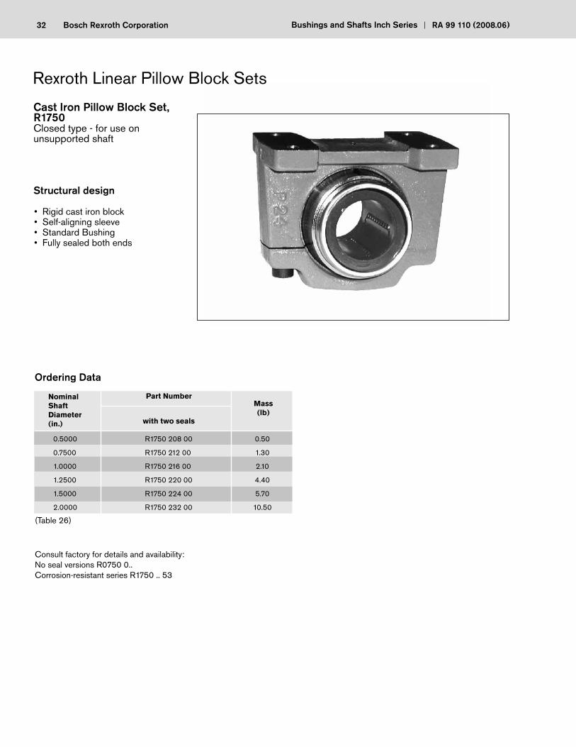
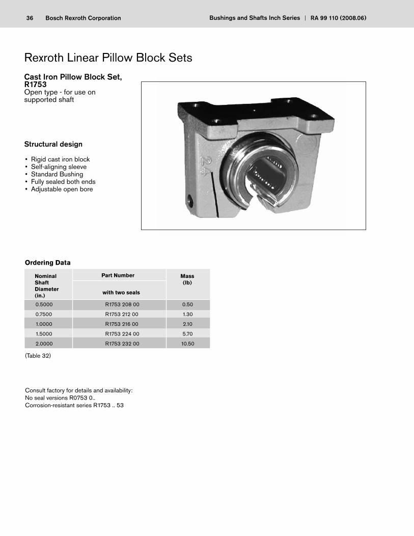
Cast Iron Pillow Block Set, R1750Closed type - for use on unsupported shaft
Structural design
0.5000
0.7500
1.0000
1.2500
1.5000
2.0000
R1750 208 00
R1750 212 00
R1750 216 00
R1750 220 00
R1750 224 00
R1750 232 00
0.50
1.30
2.10
4.40
5.70
10.50
NominalShaftDiameter(in.)
Part Number
with two seals
Mass(lb)
Ordering Data
• Rigid cast iron block• Self-aligning sleeve• Standard Bushing• Fully sealed both ends
Consult factory for details and availability:No seal versions R0750 0..Corrosion-resistant series R1750 .. 53
(Table 26)
33Bosch Rexroth CoporationRA 99 110 (2008.06) Bushings and Shafts Inch Series
(Table 27)
.5000
.7500
1.0000
1.2500
1.5000
2.0000
0.875
1.125
1.375
1.750
2.000
2.500
2.000
2.750
3.250
4.000
4.750
6.000
1.500
2.000
2.250
2.750
3.000
3.500
1.6250
2.1250
2.5625
3.2500
3.7500
4.7500
1.500
2.000
2.500
3.000
3.500
4.500
Nominal Shaft Diameter
B CW D E(2)
1.000
1.375
1.500
1.875
2.000
2.500
F(3)A(1)
1.250
1.625
2.250
2.625
3.000
4.000
G(4) J
0.2500
0.3125
0.3750
0.4375
0.5000
0.6250
K
0.5000
0.6250
1.0000
1.2500
1.4375
1.6250
0.5000
0.7500
1.0000
1.2500
1.5000
2.0000
115
194
221
353
491
860
176
308
353
617
905
1787
4
5
6
6
6
6
NominalShaftDiameter(in.)
Load Capacity
dyn. stat.
C (lbf) Co (lbf)
No. ofBallCircuits
Specifi cations
(Table 28)
HMounting Hole
Bolt Hole
#8
#10
1/4
5/16
5/16
3/8
3/16
7/32
9/32
11/32
11/32
13/32
Notes:
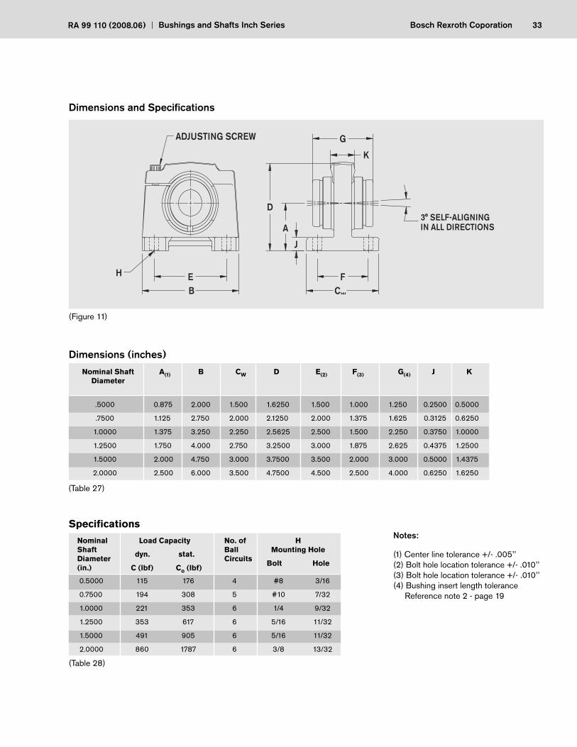
(Figure 11)
BEH
ADJUSTING SCREW
3° SELF-ALIGNINGIN ALL DIRECTIONS
D
A
J
FC
G
K
w
Dimensions and Specifi cations
(1) Center line tolerance +/- .005’’(2) Bolt hole location tolerance +/- .010’’(3) Bolt hole location tolerance +/- .010’’(4) Bushing insert length tolerance Reference note 2 - page 19
34 Bosch Rexroth Corporation Bushings and Shafts Inch Series RA 99 110 (2008.06)
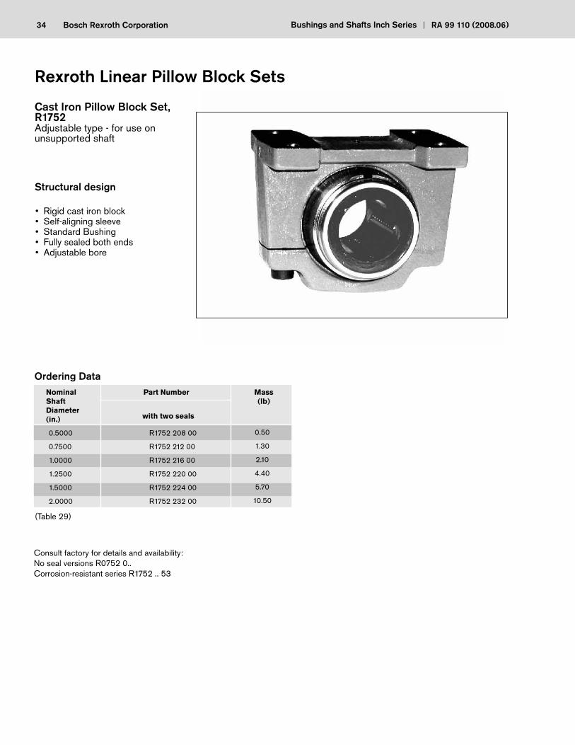
Cast Iron Pillow Block Set, R1752Adjustable type - for use on unsupported shaft
Structural design
Rexroth Linear Pillow Block Sets
0.5000
0.7500
1.0000
1.2500
1.5000
2.0000
R1752 208 00
R1752 212 00
R1752 216 00
R1752 220 00
R1752 224 00
R1752 232 00
0.50
1.30
2.10
4.40
5.70
10.50
NominalShaftDiameter(in.)
Part Number
with two seals
Mass(lb)
Ordering Data
• Rigid cast iron block• Self-aligning sleeve• Standard Bushing• Fully sealed both ends• Adjustable bore
Consult factory for details and availability:No seal versions R0752 0..Corrosion-resistant series R1752 .. 53
(Table 29)
35Bosch Rexroth CoporationRA 99 110 (2008.06) Bushings and Shafts Inch Series
0.5000
0.7500
1.0000
1.2500
1.5000
2.0000
115
194
221
353
491
860
176
308
353
617
905
1787
4
5
6
6
6
6
NominalShaftDiameter(in.)
Load Capacity
dyn. stat.
C (lbf) Co (lbf)
No. ofcircuits
Specifi cations
(Table 31)
HMounting Hole
Bolt Hole
#8
#10
1/4
5/16
5/16
3/8
3/16
7/32
9/32
11/32
11/32
13/32
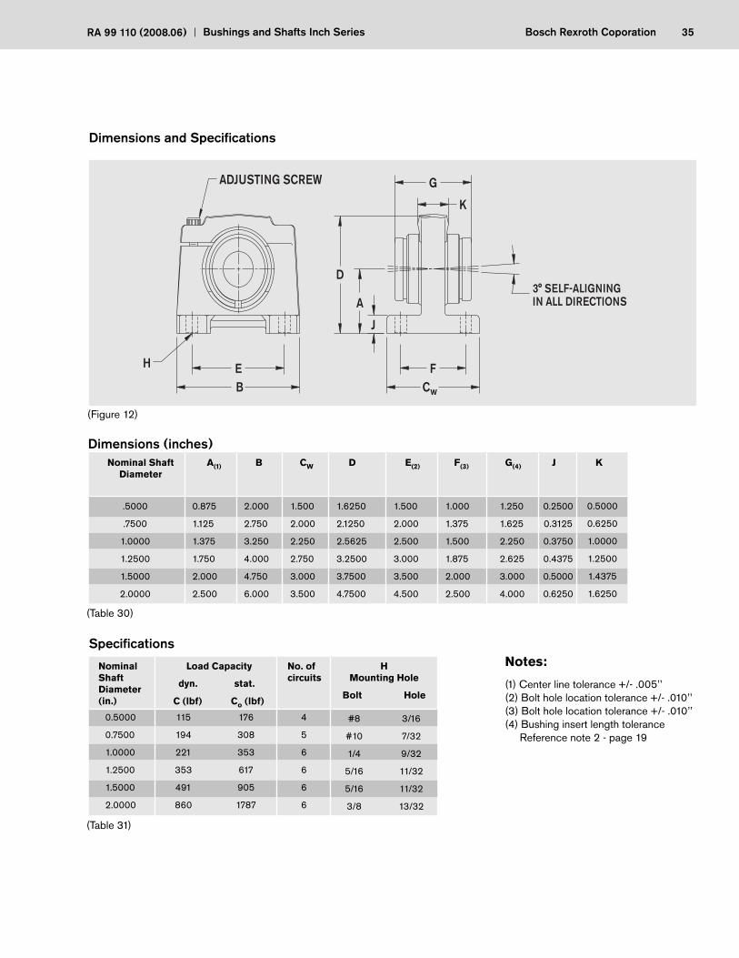
Notes:
(1) Center line tolerance +/- .005’’(2) Bolt hole location tolerance +/- .010’’(3) Bolt hole location tolerance +/- .010’’(4) Bushing insert length tolerance Reference note 2 - page 19
(Table 30)
.5000
.7500
1.0000
1.2500
1.5000
2.0000
0.875
1.125
1.375
1.750
2.000
2.500
2.000
2.750
3.250
4.000
4.750
6.000
1.500
2.000
2.250
2.750
3.000
3.500
1.6250
2.1250
2.5625
3.2500
3.7500
4.7500
1.500
2.000
2.500
3.000
3.500
4.500
Nominal Shaft Diameter
B CW D E(2)
Dimensions (inches)
1.000
1.375
1.500
1.875
2.000
2.500
F(3)A(1)
1.250
1.625
2.250
2.625
3.000
4.000
G(4) J
0.2500
0.3125
0.3750
0.4375
0.5000
0.6250
K
0.5000
0.6250
1.0000
1.2500
1.4375
1.6250
(Figure 12)
BEH
ADJUSTING SCREW
3° SELF-ALIGNINGIN ALL DIRECTIONS
D
A
J
FC
G
K
w
Dimensions and Specifi cations
36 Bosch Rexroth Corporation Bushings and Shafts Inch Series RA 99 110 (2008.06)
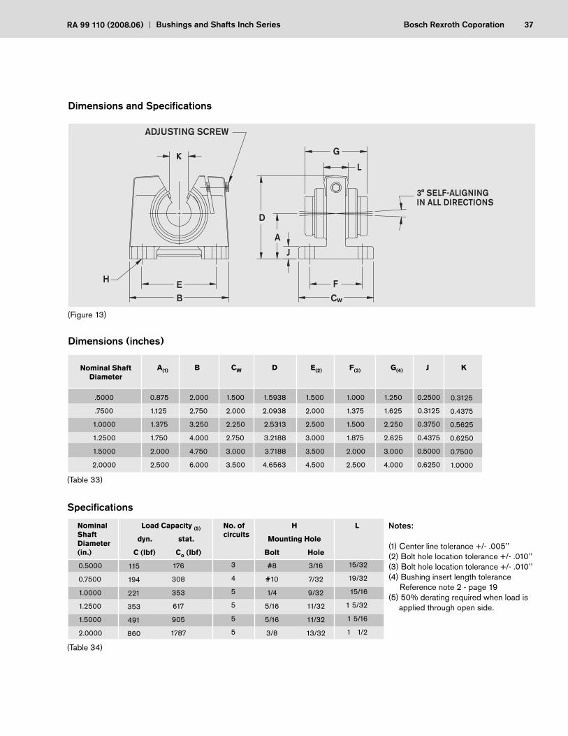
Cast Iron Pillow Block Set, R1753Open type - for use on supported shaft
Structural design
0.5000
0.7500
1.0000
1.5000
2.0000
R1753 208 00
R1753 212 00
R1753 216 00
R1753 224 00
R1753 232 00
0.50
1.30
2.10
5.70
10.50
NominalShaftDiameter(in.)
Part Number
with two seals
Mass(lb)
Ordering Data
(Table 32)
• Rigid cast iron block• Self-aligning sleeve• Standard Bushing• Fully sealed both ends• Adjustable open bore
Consult factory for details and availability:No seal versions R0753 0..Corrosion-resistant series R1753 .. 53
37Bosch Rexroth CoporationRA 99 110 (2008.06) Bushings and Shafts Inch Series
Notes:
(1) Center line tolerance +/- .005’’(2) Bolt hole location tolerance +/- .010’’(3) Bolt hole location tolerance +/- .010’’(4) Bushing insert length tolerance Reference note 2 - page 19(5) 50% derating required when load is
applied through open side.
(Table 33)
.5000
.7500
1.0000
1.2500
1.5000
2.0000
0.875
1.125
1.375
1.750
2.000
2.500
2.000
2.750
3.250
4.000
4.750
6.000
1.500
2.000
2.250
2.750
3.000
3.500
1.5938
2.0938
2.5313
3.2188
3.7188
4.6563
1.500
2.000
2.500
3.000
3.500
4.500
Nominal Shaft Diameter
B CW D E(2)
Dimensions (inches)
1.000
1.375
1.500
1.875
2.000
2.500
F(3)A(1)
1.250
1.625
2.250
2.625
3.000
4.000
G(4) J
0.2500
0.3125
0.3750
0.4375
0.5000
0.6250
K
0.3125
0.4375
0.5625
0.6250
0.7500
1.0000
0.5000
0.7500
1.0000
1.2500
1.5000
2.0000
115
194
221
353
491
860
176
308
353
617
905
1787
3
4
5
5
5
5
NominalShaftDiameter(in.)
Load Capacity (5)
dyn. stat.
C (lbf) Co (lbf)
No. ofcircuits
(Table 34)
H
Mounting Hole
Bolt Hole
#8
#10
1/4
5/16
5/16
3/8
3/16
7/32
9/32
11/32
11/32
13/32
15/32
19/32
15/16
1 5/32
1 5/16
1 1/2
L
BEH
ADJUSTING SCREW
3° SELF-ALIGNINGIN ALL DIRECTIONS
D
A
J
FC
G
L
w
Dimensions and Specifi cations
(Figure 13)
38 Bosch Rexroth Corporation Bushings and Shafts Inch Series RA 99 110 (2008.06)
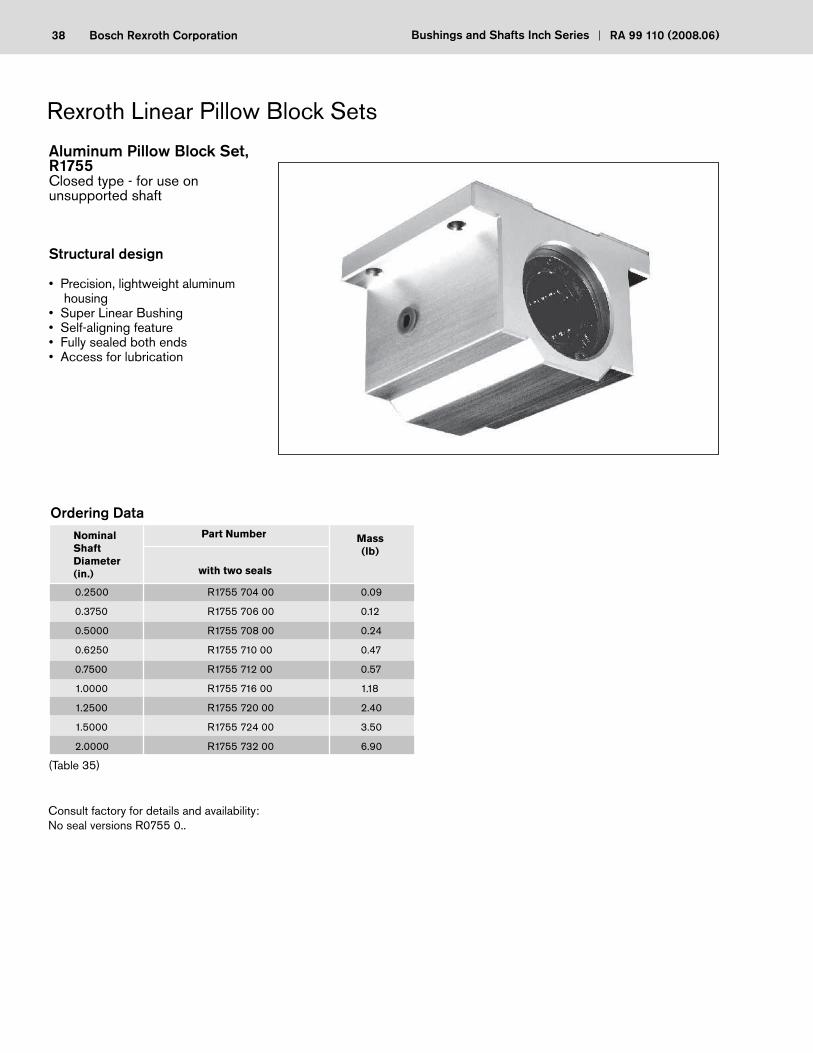
Aluminum Pillow Block Set, R1755Closed type - for use on unsupported shaft
Structural design
• Precision, lightweight aluminum housing
• Super Linear Bushing• Self-aligning feature• Fully sealed both ends• Access for lubrication
0.2500
0.3750
0.5000
0.6250
0.7500
1.0000
1.2500
1.5000
2.0000
R1755 704 00
R1755 706 00
R1755 708 00
R1755 710 00
R1755 712 00
R1755 716 00
R1755 720 00
R1755 724 00
R1755 732 00
0.09
0.12
0.24
0.47
0.57
1.18
2.40
3.50
6.90
NominalShaftDiameter(in.)
Part Number
with two seals
Mass(lb)
Ordering Data
(Table 35)
Consult factory for details and availability:No seal versions R0755 0..

39Bosch Rexroth CoporationRA 99 110 (2008.06) Bushings and Shafts Inch Series
Dimensions and Specifi cations
Notes:
(1) Center line tolerance +/- .0012’’(2) Bolt hole location tolerance +/- .010’’(3) Bolt hole location tolerance +/- .010’’
* Provided with push-in lube fi tting for sizes .2500’’ to .5000’’.
Sizes .6250’’ to 2’’ offer a 1/4 - 28 tapped hole with plug.
(Table 36)
0.2500
0.3750
0.5000
0.6250
0.7500
1.0000
1.2500
1.5000
2.0000
0.4370
0.5000
0.6870
0.8750
0.9370
1.1870
1.5000
1.7500
2.1250
1.625
1.750
2.000
2.500
2.750
3.250
4.000
4.750
6.000
1.188
1.313
1.688
1.938
2.063
2.813
3.625
4.000
5.000
0.813
0.938
1.250
1.625
1.750
2.188
2.813
3.250
4.063
1.312
1.437
1.688
2.125
2.375
2.875
3.500
4.125
5.250
Nominal Shaft Diameter
B CL D E(2)
0.750
0.875
1.000
1.125
1.250
1.750
2.000
2.500
3.250
F(3)A(1)
1.000
1.125
1.375
1.750
1.875
2.375
3.000
3.500
4.500
G J
0.188
0.188
0.250
0.281
0.313
0.375
0.438
0.500
0.625
K
0.750
0.875
1.125
1.437
1.563
1.938
2.500
2.875
3.625
0.2500
0.3750
0.5000
0.6250
0.7500
1.0000
1.2500
1.5000
2.0000
60
95
230
400
470
850
1230
1483
2430
4
4
4
5
6
6
6
6
6
NominalShaftDiameter(in.)
Load Capacity
dyn. stat.
C (lbf) Co (lbf)
No. ofBallCircuits
(Table 37)
H
Mounting Hole
Bolt Hole
#6
#6
#6
#8
#8
#10
#10
1/4
3/8
5/32
5/32
5/32
3/16
3/16
7/32
7/32
9/32
13/32
0.394
0.433
0.591
0.709
0.717
0.969
1.311
1.378
1.654
L
80
120
290
502
592
1062
1532
1852
3038
(Figure 14)
BE
H
LUBRICATION PORT*
DA
J
FC
G
K
+/- 0.5° SELF-ALIGNINGIN ALL DIRECTIONS
L
40 Bosch Rexroth Corporation Bushings and Shafts Inch Series RA 99 110 (2008.06)
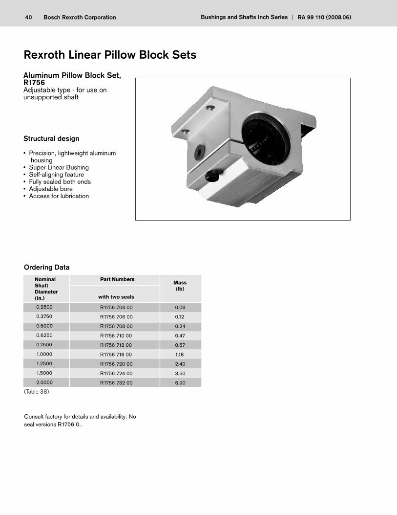
Aluminum Pillow Block Set, R1756Adjustable type - for use on unsupported shaft
Structural design
• Precision, lightweight aluminum housing
• Super Linear Bushing• Self-aligning feature• Fully sealed both ends• Adjustable bore• Access for lubrication
Rexroth Linear Pillow Block Sets
0.2500
0.3750
0.5000
0.6250
0.7500
1.0000
1.2500
1.5000
2.0000
R1756 704 00
R1756 706 00
R1756 708 00
R1756 710 00
R1756 712 00
R1756 716 00
R1756 720 00
R1756 724 00
R1756 732 00
0.09
0.12
0.24
0.47
0.57
1.18
2.40
3.50
6.90
NominalShaftDiameter(in.)
Part Numbers
with two seals
Mass(lb)
Ordering Data
(Table 38)
Consult factory for details and availability: No seal versions R1756 0..
41Bosch Rexroth CoporationRA 99 110 (2008.06) Bushings and Shafts Inch Series
Dimensions and Specifi cations
Notes:
(1) Center line tolerance +/- .0012’’(2) Bolt hole location tolerance +/- .010’’(3) Bolt hole location tolerance +/- .010’’
* Provided with push-in lube fi tting for sizes .2500’’ to .5000’’. Sizes .6250’’ to 2’’ offer a 1/4 - 28
tapped hole with plug.
(Table 39)
0.2500
0.3750
0.5000
0.6250
0.7500
1.0000
1.2500
1.5000
2.0000
0.4370
0.5000
0.6870
0.8750
0.9370
1.1870
1.5000
1.7500
2.1250
1.625
1.750
2.000
2.500
2.750
3.250
4.000
4.750
6.000
1.188
1.313
1.688
1.938
2.063
2.813
3.625
4.000
5.000
0.813
0.938
1.250
1.625
1.750
2.188
2.813
3.250
4.063
1.312
1.437
1.688
2.125
2.375
2.875
3.500
4.125
5.250
Nominal Shaft Diameter
B CL D E(2)
Dimensions (inches)
0.750
0.875
1.000
1.125
1.250
1.750
2.000
2.500
3.250
F(3)A(1)
1.000
1.125
1.375
1.750
1.875
2.375
3.000
3.500
4.500
G J
0.188
0.188
0.250
0.281
0.313
0.375
0.438
0.500
0.625
K
0.750
0.875
1.125
1.437
1.563
1.938
2.500
2.875
3.625
0.2500
0.3750
0.5000
0.6250
0.7500
1.0000
1.2500
1.5000
2.0000
60
95
230
400
470
850
1230
1483
2430
4
4
4
5
6
6
6
6
6
NominalShaftDiameter(in.)
Load Capacity
dyn. stat.
C (lbf) Co (lbf)
No. ofBallCircuits
Specifi cations
(Table 40)
H
Mounting Hole
Bolt Hole
#6
#6
#6
#8
#8
#10
#10
1/4
3/8
5/32
5/32
5/32
3/16
3/16
7/32
7/32
9/32
13/32
0.394
0.433
0.591
0.709
0.717
0.969
1.311
1.378
1.654
L
80
120
290
502
592
1062
1532
1852
3038
(Figure 15)
BE
H
D
A
FC
G
K
J
LUBRICATION PORT*
L
+/- 0.5° SELF-ALIGNINGIN ALL DIRECTIONS
42 Bosch Rexroth Corporation Bushings and Shafts Inch Series RA 99 110 (2008.06)
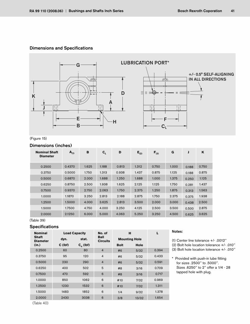
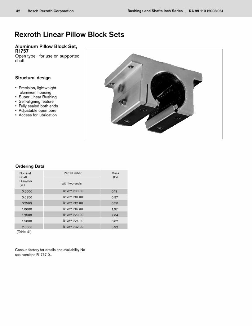
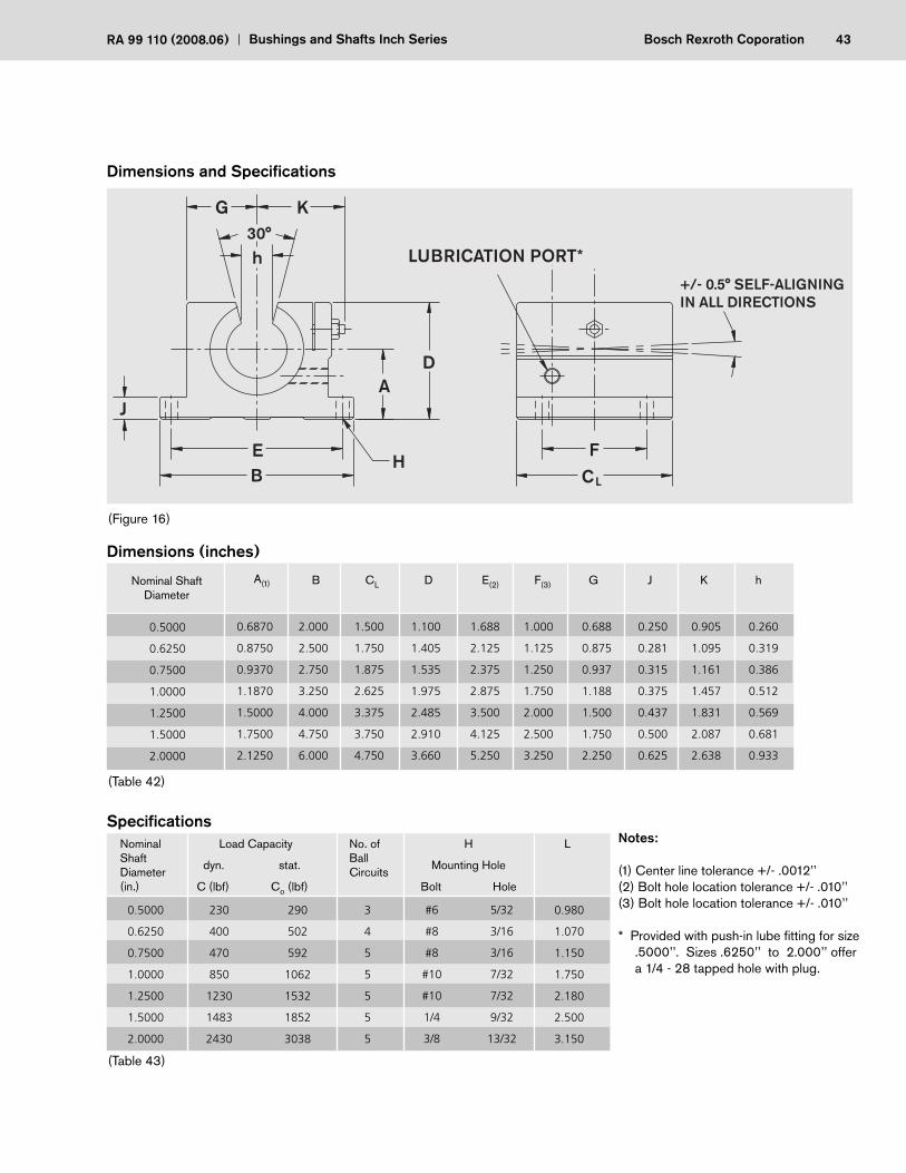
Aluminum Pillow Block Set, R1757Open type - for use on supported shaft
Structural design
• Precision, lightweight aluminum housing
• Super Linear Bushing• Self-aligning feature• Fully sealed both ends• Adjustable open bore• Access for lubrication
Rexroth Linear Pillow Block Sets
Ordering Data
Consult factory for details and availability:No seal versions R1757 0..
0.5000
0.6250
0.7500
1.0000
1.2500
1.5000
2.0000
R1757-708 00
R1757 710 00
R1757 712 00
R1757 716 00
R1757 720 00
R1757 724 00
R1757 732 00
0.19
0.37
0.50
1.07
2.04
3.07
5.92
NominalShaftDiameter(in.)
Part Number
with two seals
Mass(lb)
(Table 41)
43Bosch Rexroth CoporationRA 99 110 (2008.06) Bushings and Shafts Inch Series
0.5000
0.6250
0.7500
1.0000
1.2500
1.5000
2.0000
230
400
470
850
1230
1483
2430
290
502
592
1062
1532
1852
3038
3
4
5
5
5
5
5
NominalShaftDiameter(in.)
Load Capacity
dyn. stat.
C (lbf) Co (lbf)
No. ofBallCircuits
Specifi cations
(Table 43)
H
Mounting Hole
Bolt Hole
#6
#8
#8
#10
#10
1/4
3/8
5/32
3/16
3/16
7/32
7/32
9/32
13/32
0.980
1.070
1.150
1.750
2.180
2.500
3.150
L
(Table 42)
0.5000
0.6250
0.7500
1.0000
1.2500
1.5000
2.0000
0.6870
0.8750
0.9370
1.1870
1.5000
1.7500
2.1250
2.000
2.500
2.750
3.250
4.000
4.750
6.000
1.500
1.750
1.875
2.625
3.375
3.750
4.750
1.100
1.405
1.535
1.975
2.485
2.910
3.660
1.688
2.125
2.375
2.875
3.500
4.125
5.250
Nominal Shaft Diameter
B CL D E(2)
1.000
1.125
1.250
1.750
2.000
2.500
3.250
F(3)A(1)
0.688
0.875
0.937
1.188
1.500
1.750
2.250
G J
0.250
0.281
0.315
0.375
0.437
0.500
0.625
K
0.905
1.095
1.161
1.457
1.831
2.087
2.638
0.260
0.319
0.386
0.512
0.569
0.681
0.933
h
Notes:
(1) Center line tolerance +/- .0012’’(2) Bolt hole location tolerance +/- .010’’(3) Bolt hole location tolerance +/- .010’’
* Provided with push-in lube fi tting for size .5000’’. Sizes .6250’’ to 2.000’’ offer
a 1/4 - 28 tapped hole with plug.
Dimensions and Specifi cations
(Figure 16)
Dimensions (inches)
BE
H
DA
FC
G
J
K
h30°
LUBRICATION PORT*
L
+/- 0.5° SELF-ALIGNINGIN ALL DIRECTIONS

44 Bosch Rexroth Corporation Bushings and Shafts Inch Series RA 99 110 (2008.06)
Aluminum Twin Pillow Block Set, R1760Closed type - for use on unsupported shaft
Structural design
• Precision, lightweight aluminum housing• Twin style housing• Two Super Linear Bushings• Self-aligning feature• Fully sealed both ends• Access for lubrication
Rexroth Linear Twin Pillow Block Sets
0.2500
0.3750
0.5000
0.6250
0.7500
1.0000
1.2500
1.5000
R1760 704 00
R1760 706 00
R1760 708 00
R1760 710 00
R1760 712 00
R1760 716 00
R1760 720 00
R1760 724 00
0.19
0.24
0.49
0.96
1.25
2.50
5.00
7.80
NominalShaftDiameter(in.)
Part Number
with two seals
Mass(lb)
Ordering Data
(Table 44)
Consult factory for details and availability: No seal versions R1760 0..

45Bosch Rexroth CoporationRA 99 110 (2008.06) Bushings and Shafts Inch Series
Dimensions and Specifi cations
Notes:
(1) Center line tolerance +/- .0012’’(2) Bolt hole location tolerance +/- .010’’(3) Bolt hole location tolerance +/- .010’’
* Provided with push-in lube fi tting for sizes .2500’’ to .5000’’. Sizes .6250’’ to 1.500’’ offer a 1/4 - 28 tapped hole with plug.
(Table 45)
0.2500
0.3750
0.5000
0.6250
0.7500
1.0000
1.2500
1.5000
0.4370
0.5000
0.6870
0.8750
0.9370
1.1870
1.5000
1.7500
1.625
1.750
2.000
2.500
2.750
3.250
4.000
4.750
2.500
2.750
3.500
4.000
4.500
6.000
7.500
9.000
0.813
0.938
1.250
1.625
1.750
2.188
2.813
3.250
1.312
1.437
1.688
2.125
2.375
2.875
3.500
4.125
Nominal Shaft Diameter
B CL E(2)
Dimensions (inches)
2.000
2.250
2.500
3.000
3.500
4.500
5.500
6.500
F(3)A(1)
1.000
1.125
1.375
1.750
1.875
2.375
3.000
3.500
G J
0.188
0.188
0.250
0.281
0.313
0.375
0.438
0.500
K
0.750
0.875
1.125
1.437
1.563
1.938
2.500
2.875
0.2500
0.3750
0.5000
0.6250
0.7500
1.0000
1.2500
1.5000
96
150
370
640
750
1360
1925
2360
160
240
580
1000
1184
2124
3064
3685
8
8
8
10
12
12
12
12
NominalShaftDiameter(in.)
Load Capacity
dyn. stat.
C (lbf) Co (lbf)
No. ofBallCircuits
Specifi cations
(Table 46)
H
Mounting Hole
Bolt Hole
#6
#6
#6
#8
#8
#10
#10
1/4
5/32
5/32
5/32
3/16
3/16
7/32
7/32
9/32
D
(Figure 17)
BE H
D
A
FC
G
J
K
LUBRICATION PORT*
L
46 Bosch Rexroth Corporation Bushings and Shafts Inch Series RA 99 110 (2008.06)
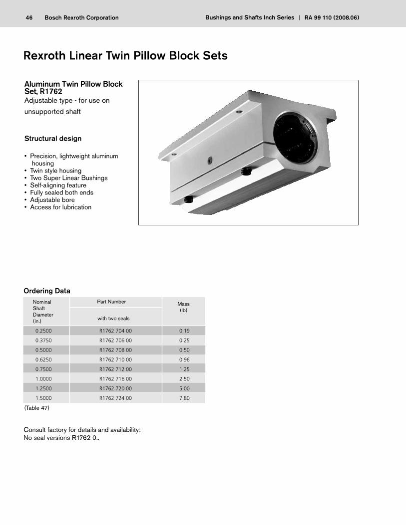
Aluminum Twin Pillow Block Set, R1762Adjustable type - for use on
unsupported shaft
Structural design
• Precision, lightweight aluminum housing
• Twin style housing• Two Super Linear Bushings• Self-aligning feature• Fully sealed both ends• Adjustable bore• Access for lubrication
Rexroth Linear Twin Pillow Block Sets
0.2500
0.3750
0.5000
0.6250
0.7500
1.0000
1.2500
1.5000
R1762 704 00
R1762 706 00
R1762 708 00
R1762 710 00
R1762 712 00
R1762 716 00
R1762 720 00
R1762 724 00
0.19
0.25
0.50
0.96
1.25
2.50
5.00
7.80
NominalShaftDiameter(in.)
Part Number
with two seals
Mass(lb)
Ordering Data
(Table 47)
Consult factory for details and availability: No seal versions R1762 0..
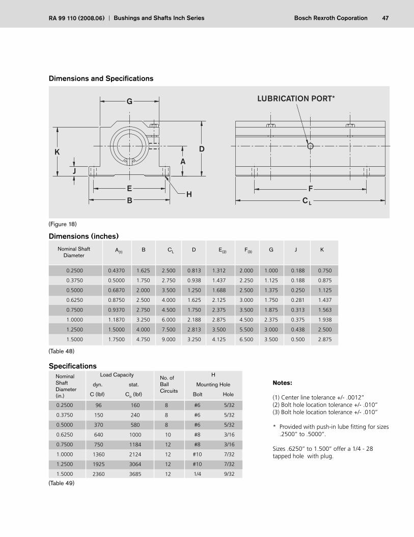
47Bosch Rexroth CoporationRA 99 110 (2008.06) Bushings and Shafts Inch Series
Dimensions and Specifi cations
Notes:
(1) Center line tolerance +/- .0012’’(2) Bolt hole location tolerance +/- .010’’(3) Bolt hole location tolerance +/- .010’’
* Provided with push-in lube fitting for sizes .2500’’ to .5000’’.
Sizes .6250’’ to 1.500’’ offer a 1/4 - 28 tapped hole with plug.
0.2500
0.3750
0.5000
0.6250
0.7500
1.0000
1.2500
1.5000
96
150
370
640
750
1360
1925
2360
160
240
580
1000
1184
2124
3064
3685
8
8
8
10
12
12
12
12
NominalShaftDiameter(in.)
Load Capacity
dyn. stat.
C (lbf) Co (lbf)
No. ofBallCircuits
Specifi cations
(Table 49)
H
Mounting Hole
Bolt Hole
#6
#6
#6
#8
#8
#10
#10
1/4
5/32
5/32
5/32
3/16
3/16
7/32
7/32
9/32
(Table 48)
0.2500
0.3750
0.5000
0.6250
0.7500
1.0000
1.2500
1.5000
0.4370
0.5000
0.6870
0.8750
0.9370
1.1870
1.5000
1.7500
1.625
1.750
2.000
2.500
2.750
3.250
4.000
4.750
2.500
2.750
3.500
4.000
4.500
6.000
7.500
9.000
0.813
0.938
1.250
1.625
1.750
2.188
2.813
3.250
1.312
1.437
1.688
2.125
2.375
2.875
3.500
4.125
Nominal Shaft Diameter
B CL D E(2)
Dimensions (inches)
2.000
2.250
2.500
3.000
3.500
4.500
5.500
6.500
F(3)A(1)
1.000
1.125
1.375
1.750
1.875
2.375
3.000
3.500
G J
0.188
0.188
0.250
0.281
0.313
0.375
0.438
0.500
K
0.750
0.875
1.125
1.437
1.563
1.938
2.500
2.875
(Figure 18)
B
EH
D
A
FC
G
J
K
LUBRICATION PORT*
L
48 Bosch Rexroth Corporation Bushings and Shafts Inch Series RA 99 110 (2008.06)
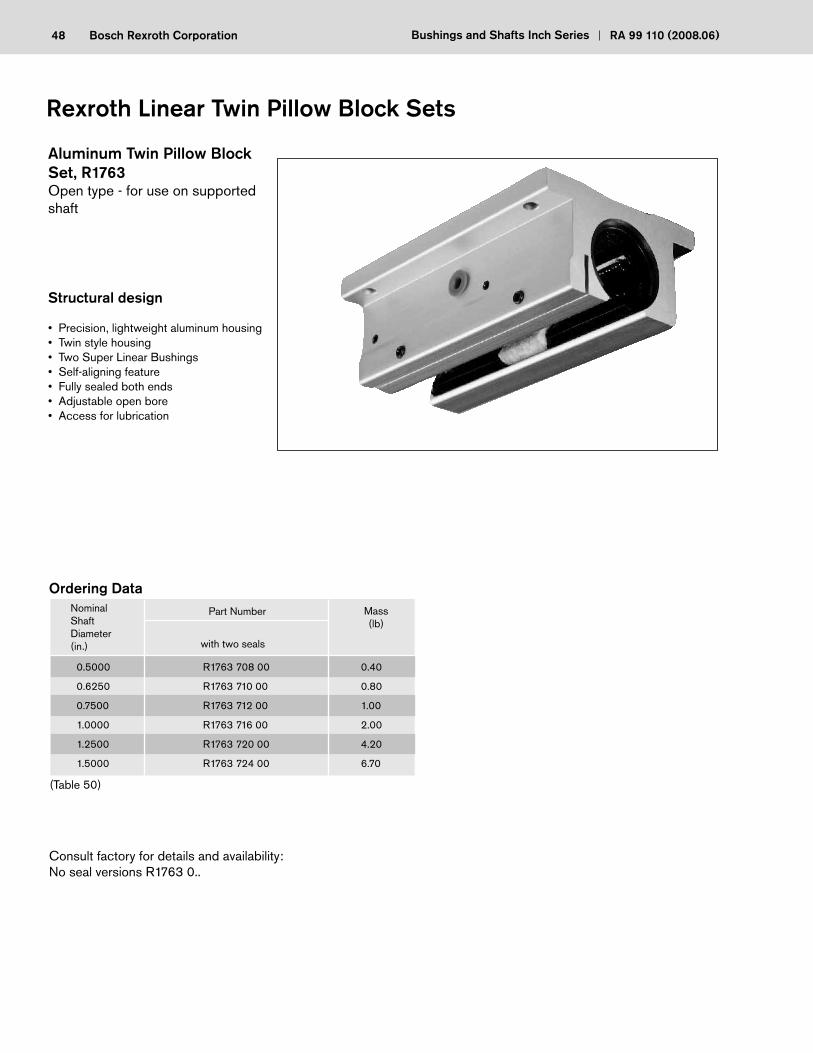
Aluminum Twin Pillow Block Set, R1763Open type - for use on supported shaft
Structural design
• Precision, lightweight aluminum housing• Twin style housing• Two Super Linear Bushings• Self-aligning feature• Fully sealed both ends• Adjustable open bore• Access for lubrication
Rexroth Linear Twin Pillow Block Sets
0.5000
0.6250
0.7500
1.0000
1.2500
1.5000
R1763 708 00
R1763 710 00
R1763 712 00
R1763 716 00
R1763 720 00
R1763 724 00
0.40
0.80
1.00
2.00
4.20
6.70
NominalShaftDiameter(in.)
Part Number
with two seals
Mass(lb)
(Table 50)
Consult factory for details and availability:No seal versions R1763 0..
Ordering Data
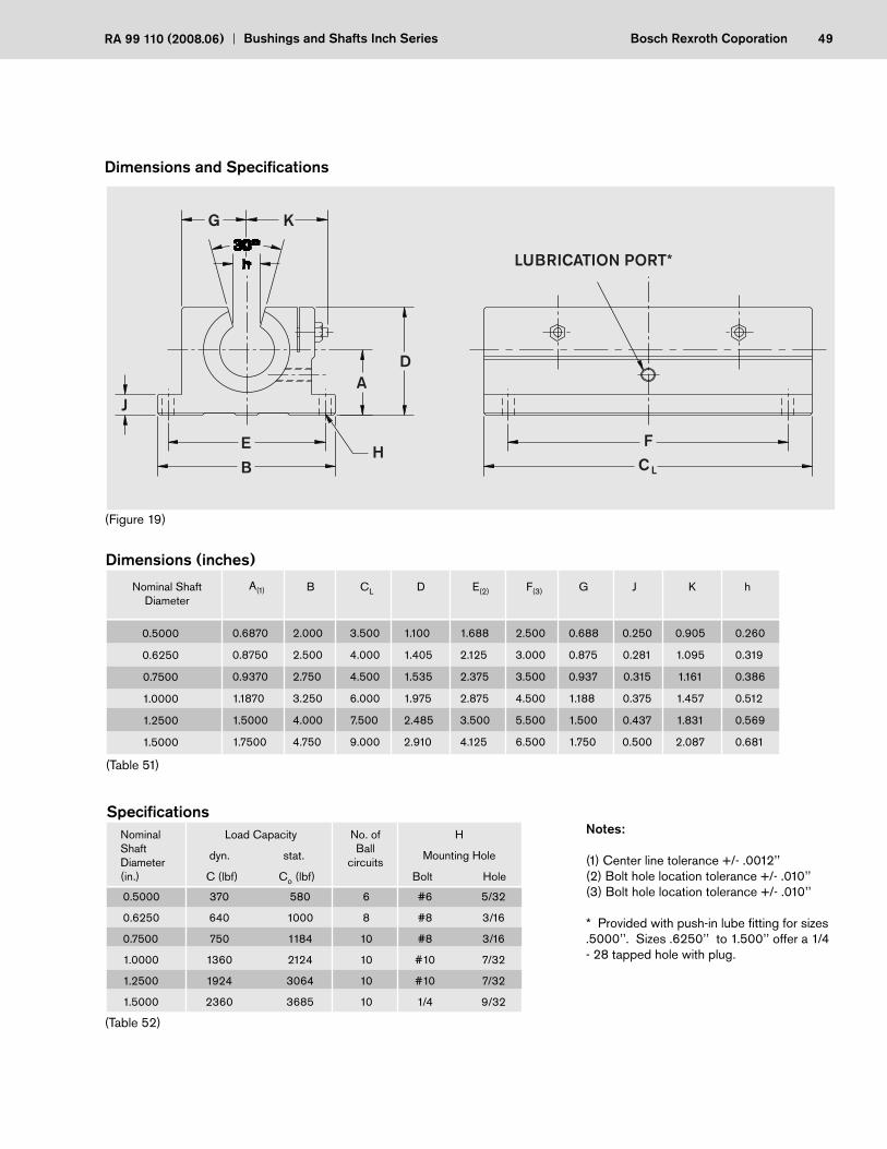
49Bosch Rexroth CoporationRA 99 110 (2008.06) Bushings and Shafts Inch Series
Dimensions and Specifi cations
0.5000
0.6250
0.7500
1.0000
1.2500
1.5000
370
640
750
1360
1924
2360
580
1000
1184
2124
3064
3685
6
8
10
10
10
10
NominalShaftDiameter(in.)
No. ofBall
circuits
Specifi cations
(Table 52)
H
Mounting Hole
Bolt Hole
#6
#8
#8
#10
#10
1/4
5/32
3/16
3/16
7/32
7/32
9/32
(Table 51)
0.5000
0.6250
0.7500
1.0000
1.2500
1.5000
0.6870
0.8750
0.9370
1.1870
1.5000
1.7500
2.000
2.500
2.750
3.250
4.000
4.750
3.500
4.000
4.500
6.000
7.500
9.000
1.100
1.405
1.535
1.975
2.485
2.910
1.688
2.125
2.375
2.875
3.500
4.125
Nominal Shaft Diameter
B CL D E(2)
Dimensions (inches)
2.500
3.000
3.500
4.500
5.500
6.500
F(3)A(1)
0.688
0.875
0.937
1.188
1.500
1.750
G J
0.250
0.281
0.315
0.375
0.437
0.500
K
0.905
1.095
1.161
1.457
1.831
2.087
0.260
0.319
0.386
0.512
0.569
0.681
h
Notes:
(1) Center line tolerance +/- .0012’’(2) Bolt hole location tolerance +/- .010’’(3) Bolt hole location tolerance +/- .010’’
* Provided with push-in lube fi tting for sizes .5000’’. Sizes .6250’’ to 1.500’’ offer a 1/4 - 28 tapped hole with plug.
Load Capacity
dyn. stat.
C (lbf) Co (lbf)
(Figure 19)
B
E H
DA
FC
G
J
K
LUBRICATION PORT*
L
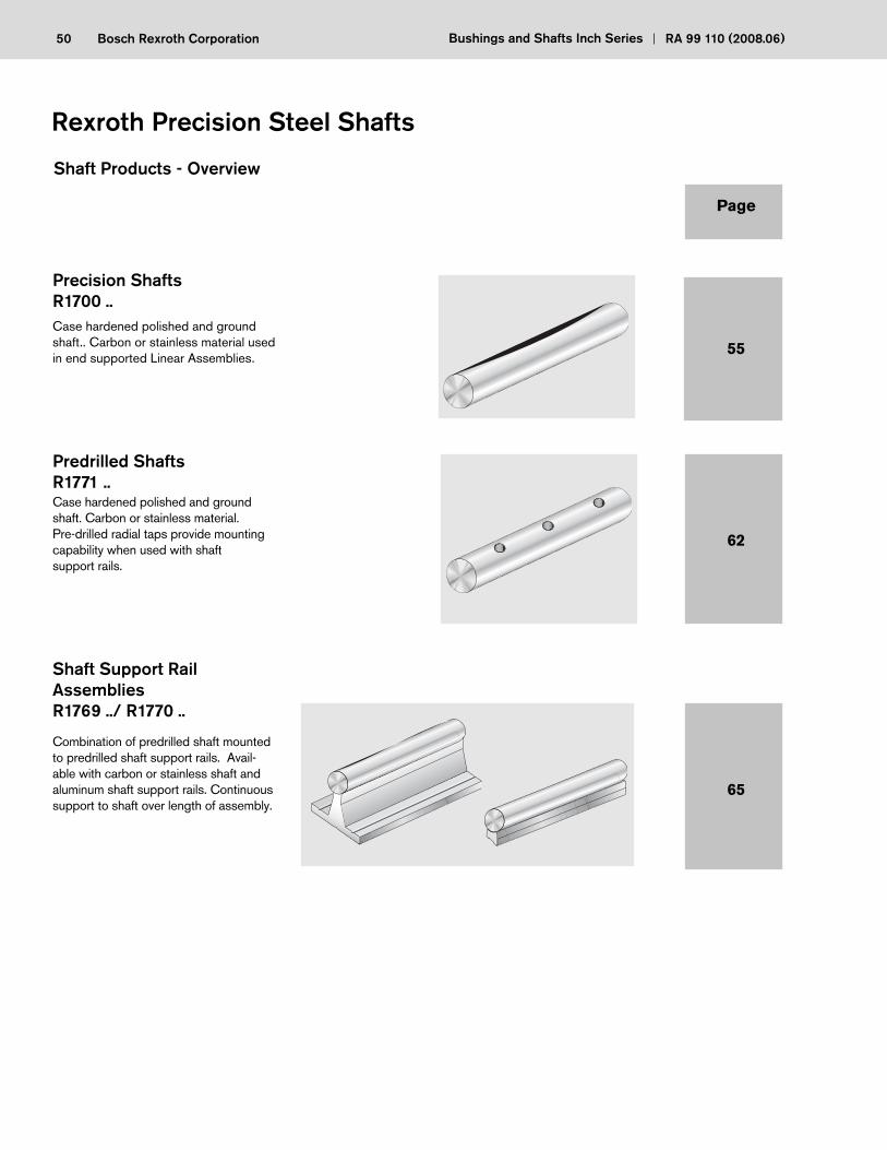
50 Bosch Rexroth Corporation Bushings and Shafts Inch Series RA 99 110 (2008.06)
Precision Shafts R1700 ..Case hardened polished and ground shaft.. Carbon or stainless material used in end supported Linear Assemblies.
Predrilled ShaftsR1771 ..Case hardened polished and ground shaft. Carbon or stainless material. Pre-drilled radial taps provide mounting capability when used with shaft support rails.
Shaft Support Rail AssembliesR1769 ../ R1770 ..
Combination of predrilled shaft mounted to predrilled shaft support rails. Avail-able with carbon or stainless shaft and aluminum shaft support rails. Continuous support to shaft over length of assembly.
Rexroth Precision Steel Shafts
Page
55
62
65
Shaft Products - Overview
51Bosch Rexroth CoporationRA 99 110 (2008.06) Bushings and Shafts Inch Series
• Guide rods
• Control rods
• Rollers
• Pistons
• Axles
• Guide pins
• Tie rods
• Spindles
• Guide columns
• Mandrels and other similar applications
• Diameter range between 1/4’’ to 4’’ nominal diameter
• Class L O.D. tolerances
• Carbon steel and stainless steel materials
• Random lengths up to 244’’ long
• Plain and predrilled shaft material
• Case hardened to Rc60-64
Precision ShaftA critical component of the Linear Bushings Assembly is the shaft. Consideration for proper surface fi nish, hardness, and diameter is essential for performance of the assembly.
Rexroth Precision Steel Shafts are induction hardened and centerless ground to ensure quality fi t and performance, complimenting the Linear Bushing line of Rexroth products.
In addition to the shaft acting as guideways with Linear Bushings, they also have a long and successful service in the following applications:
Precision Shafts offer the following features
52 Bosch Rexroth Corporation Bushings and Shafts Inch Series RA 99 110 (2008.06)
(Table 59)
(Table 60)
Technical Data
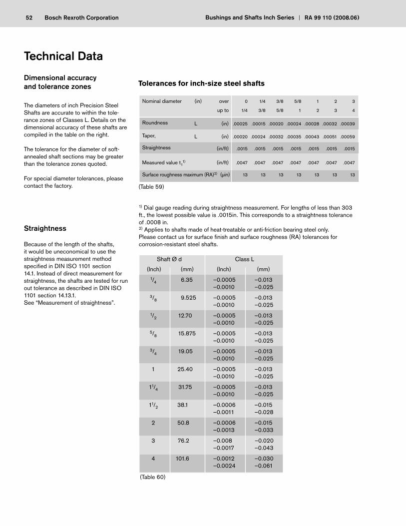
Dimensional accuracy and tolerance zones
The diameters of inch Precision Steel Shafts are accurate to within the tole-rance zones of Classes L. Details on the dimensional accuracy of these shafts are compiled in the table on the right.
The tolerance for the diameter of soft-annealed shaft sections may be greater than the tolerance zones quoted.
For special diameter tolerances, please contact the factory.
Straightness
Because of the length of the shafts, it would be uneconomical to use the straightness measurement method specifi ed in DIN ISO 1101 section 14.1. Instead of direct measurement for straightness, the shafts are tested for run out tolerance as described in DIN ISO 1101 section 14.13.1. See “Measurement of straightness”.
Shaft Ø d Class L
(Inch) (mm) (Inch) (mm)
1/4 6.35 –0.0005 –0.013 –0.0010 –0.025
3/8 9.525 –0.0005 –0.013 –0.0010 –0.025
1/2 12.70 –0.0005 –0.013 –0.0010 –0.025
5/8 15.875 –0.0005 –0.013 –0.0010 –0.025
3/4 19.05 –0.0005 –0.013 –0.0010 –0.025
1 25.40 –0.0005 –0.013 –0.0010 –0.025
11/4 31.75 –0.0005 –0.013 –0.0010 –0.025
11/2 38.1 –0.0006 –0.015 –0.0011 –0.028
2 50.8 –0.0006 –0.015 –0.0013 –0.033
3 76.2 –0.008 –0.020 –0.0017 –0.043
4 101.6 –0.0012 –0.030 –0.0024 –0.061
1) Dial gauge reading during straightness measurement. For lengths of less than 303 ft., the lowest possible value is .0015in. This corresponds to a straightness tolerance of .0008 in.2) Applies to shafts made of heat-treatable or anti-friction bearing steel only. Please contact us for surface fi nish and surface roughness (RA) tolerances for corrosion-resistant steel shafts.
Tolerances for inch-size steel shafts
Nominal diameter (in) over 0 1/4 3/8 5/8 1 2 3
up to 1/4 3/8 5/8 1 2 3 4
Roundness L (in) .00025 .00015 .00020 .00024 .00028 .00032 .00039
Taper, L (in) .00020 .00024 .00032 .00035 .00043 .00051 .00059
Straightness (in/ft) .0015 .0015 .0015 .0015 .0015 .0015 .0015
Measured value t11) (in/ft) .0047 .0047 .0047 .0047 .0047 .0047 .0047
Surface roughness maximum (RA)2) (μin) 13 13 13 13 13 13 13
53Bosch Rexroth CoporationRA 99 110 (2008.06) Bushings and Shafts Inch Series
112/458 MADE IN ENGLAND
THE RANK ORGANISATION, RANK TAYLOR HOBSON DIVISION
SPECIMEN
TALYRONDμ
MAGN FILTER
112/458 MADE IN ENGLAND
THE RANK ORGANISATION, RANK TAYLOR HOBSON DIVISION
SPECIMEN
TALYRONDμ
MAG N FILTER
58o2 58o3
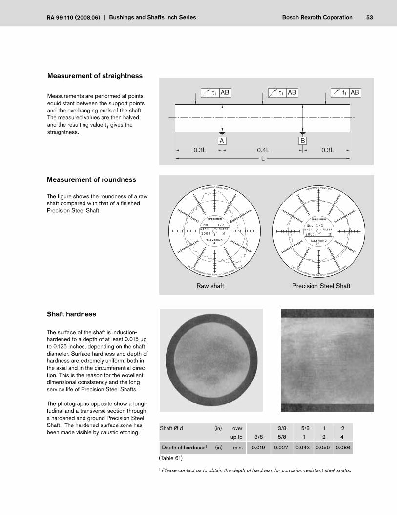
Raw shaft Precision Steel Shaft
Measurement of straightness
Measurements are performed at points equidistant between the support points and the overhanging ends of the shaft. The measured values are then halved and the resulting value t1 gives the straightness.
Measurement of roundness
The fi gure shows the roundness of a raw shaft compared with that of a fi nished Precision Steel Shaft.
Shaft hardness
The surface of the shaft is induction-hardened to a depth of at least 0.015 up to 0.125 inches, depending on the shaft diameter. Surface hardness and depth of hardness are extremely uniform, both in the axial and in the circumferential direc-tion. This is the reason for the excellent dimensional consistency and the long service life of Precision Steel Shafts.
The photographs opposite show a longi-tudinal and a transverse section through a hardened and ground Precision Steel Shaft. The hardened surface zone has been made visible by caustic etching.
Shaft Ø d (in) over 3/8 5/8 1 2
up to 3/8 5/8 1 2 4
Depth of hardness1 (in) min. 0.019 0.027 0.043 0.059 0.086
1 Please contact us to obtain the depth of hardness for corrosion-resistant steel shafts.
(Table 61)
AB
A B
AB AB
0.3LL
0.4L 0.3L
t1 t1 t1
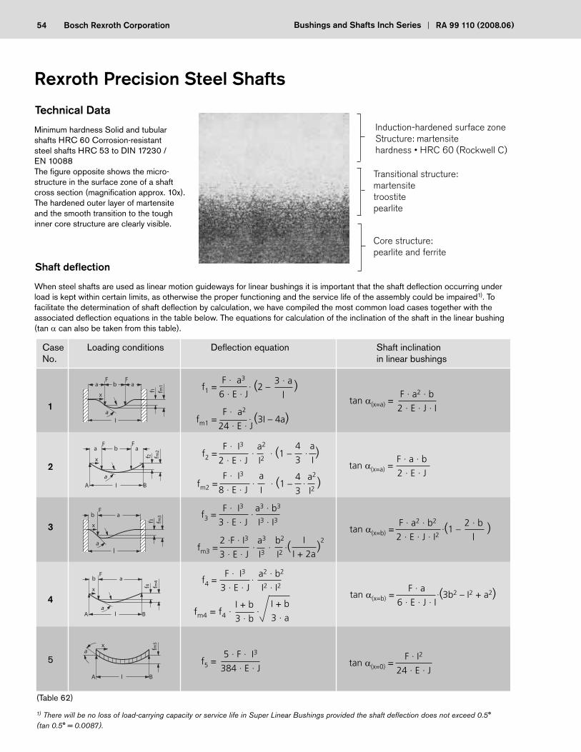
54 Bosch Rexroth Corporation Bushings and Shafts Inch Series RA 99 110 (2008.06)
Rexroth Precision Steel Shafts59o1
Minimum hardness Solid and tubular shafts HRC 60 Corrosion-resistant steel shafts HRC 53 to DIN 17230 / EN 10088The fi gure opposite shows the micro-structure in the surface zone of a shaft cross section (magnifi cation approx. 10x). The hardened outer layer of mar tensite and the smooth transition to the tough inner core structure are clearly visible.
Induction-hardened surface zoneStructure: martensite hardness • HRC 60 (Rockwell C)
Transitional structure:martensitetroostitepearlite
Core structure:pearlite and ferrite
When steel shafts are used as linear motion guideways for linear bushings it is important that the shaft defl ection occurring under load is kept within certain limits, as otherwise the proper functioning and the service life of the assembly could be impaired1). To facilitate the determination of shaft defl ection by calculation, we have compiled the most common load cases together with the associated defl ection equations in the table below. The equations for calculation of the inclination of the shaft in the linear bushing (tan can also be taken from this table).
1) There will be no loss of load-carrying capacity or service life in Super Linear Bushings provided the shaft defl ection does not exceed 0.5° (tan 0.5° = 0.0087).
Case Loading conditions Defl ection equation Shaft inclination No. in linear bushings
1
2
3
4
5
(Table 62)
Shaft defl ection
Technical Data
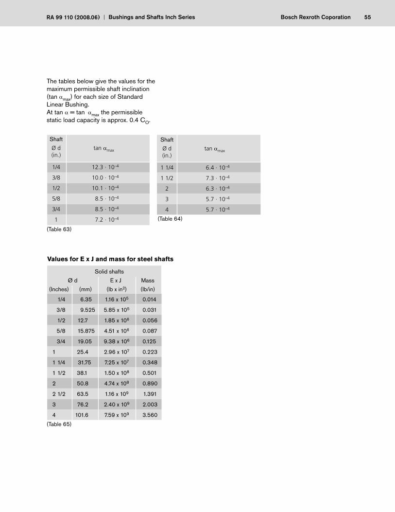
55Bosch Rexroth CoporationRA 99 110 (2008.06) Bushings and Shafts Inch Series
The tables below give the values for the maximum permissible shaft inclination (tan max) for each size of Standard Linear Bushing.At tan = tan max the permissible static load capacity is approx. 0.4 CO.
Shaft
Ø d tan max
(in.)
1/4 12.3 · 10–4
3/8 10.0 · 10–4
1/2 10.1 · 10–4
5/8 8.5 · 10–4
3/4 8.5 · 10–4
1 7.2 · 10–4
Shaft
Ø d tan max
(in.)
1 1/4 6.4 · 10–4
1 1/2 7.3 · 10–4
2 6.3 · 10–4
3 5.7 · 10–4
4 5.7 · 10–4
(Table 63)
(Table 64)
(Table 65)
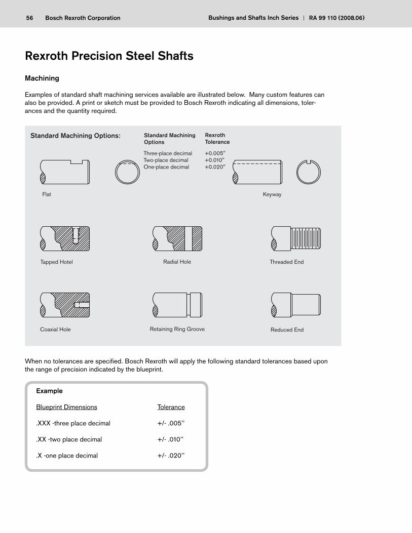
56 Bosch Rexroth Corporation Bushings and Shafts Inch Series RA 99 110 (2008.06)
Machining
Examples of standard shaft machining services available are illustrated below. Many custom features can also be provided. A print or sketch must be provided to Bosch Rexroth indicating all dimensions, toler-ances and the quantity required.
When no tolerances are specifi ed. Bosch Rexroth will apply the following standard tolerances based upon the range of precision indicated by the blueprint.
Rexroth Precision Steel Shafts
Example
Blueprint Dimensions Tolerance
.XXX -three place decimal +/- .005’’
.XX -two place decimal +/- .010’’
.X -one place decimal +/- .020’’
Standard Machining Options: Standard Machining Options
Rexroth Tolerance
Three-place decimal +0.005"Two-place decimal +0.010"One-place decimal +0.020"
Flat Keyway
Tapped Hotel
Coaxial Hole Retaining Ring Groove
Radial Hole Threaded End
Reduced End
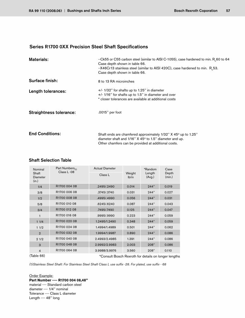
57Bosch Rexroth CoporationRA 99 110 (2008.06) Bushings and Shafts Inch Series
Series R1700 0XX Precision Steel Shaft Specifi cations
(1)Stainless Steel Shaft: For Stainless Steel Shaft Class L use suffi x -28. For plated, use suffi x - 68
Order Example:Part Number ---- R1700 004 08,48’’material ---- Standard carbon steeldiameter ---- 1/4’’ nominalTolerance ---- Class L diameterLength ---- 48’’ long
1/4
3/8
1/2
5/8
3/4
1
1 1/4
1 1/2
2
2 1/2
3
4
R1700 004 08
R1700 006 08
R1700 008 08
R1700 010 08
R1700 012 08
R1700 016 08
R1700 020 08
R1700 024 08
R1700 032 08
R1700 040 08
R1700 048 08
R1700 064 08
.2495/.2490
.3745/.3740
.4995/.4990
.6245/.6240
.7495/.7490
.9995/.9990
1.2495/1.2490
1.4994/1.4989
1.9994/1.9987
2.4993/2.4985
2.9992/2.9983
3.9988/3.9976
0.014
0.031
0.056
0.087
0.125
0.223
0.348
0.501
0.890
1.391
2.003
3.560
244’’
244’’
244’’
244’’
244’’
244’’
244’’
244’’
244’’
244’’
208’’
208’’
0.019
0.027
0.031
0.043
0.047
0.059
0.059
0.062
0.086
0.086
0.086
0.110
Nominal ShaftDiameter(in.)
Part Numbers(1) Class L -08
Actual Diameter
Class L Weight lb/in
*RandomLength(Avg.)
CaseDepth(min.)
(Table 66) *Consult Bosch Rexroth for details on longer lengths
--Ck55 or C55 carbon steel (similar to AISI C-1055), case hardened to min. Rc60 to 64Case depth shown in table 66.--X46Cr13 stainless steel (similar to AISI 420C), case hardened to min. Rc53.Case depth shown in table 66.
8 to 13 RA microinches
+/- 1/32’’ for shafts up to 1.25’’ in diameter+/- 1/16’’ for shafts up to 1.5’’ in diameter and over* closer tolerances are available at additional costs
.0015’’ per foot
Shaft ends are chamfered approximately 1/32’’ X 45o up to 1.25’’ diameter shaft and 1/16’’ X 45o to 1.5’’ diameter and up. Other chamfers can be provided at additional costs.
Materials:
Surface fi nish:
Length tolerances:
Straightness tolerance:
End Conditions:
Shaft Selection Table

58 Bosch Rexroth Corporation Bushings and Shafts Inch Series RA 99 110 (2008.06)
Order Example:Part Number ---- R1771 012 08,144’’material----Standard carbon steeldiameter----3/4’’ nominalTolerance----Class L diameterLength----144’’ long
Rexroth Precision Steel Shafts
1/2
5/8
3/4
1
1 1/4
1 1/2
2
2.00
2.00
3.00
3.00
3.00
4.00
4.00
4.00
4.00
6.00
6.00
6.00
8.00
8.00
200”
200”
200”
200’’
200’’
200’’
200’’
#6-32
#8-32
#10-32
1/4-20
5/16-18
3/8-16
1/2-13
0.250
0.320
0.380
0.500
0.630
0.750
1.000
Nominal ShaftDiameter(in.)
Part Numbers(1)Carbon Steel Ck-55 Stainless Steel X46 Class L Class L
A+/- 0.005
B+/- 0.010
CTSize
DDepth
*Random Lengths (Avg.)
(Table 67)
Shaft Selection Table
Series R1771 0XX Pre-drilled Shaft Specifi cations
R1771 008 08 R1771 008 28
R1771 010 08 R1771 010 28
R1771 012 08 R1771 012 28
R1771 016 08 R1771 016 28
R1771 020 08 R1771 020 28
R1771 024 08 R1771 024 28
R1771 032 08 R1771 032 28
(Figure 23)
(Old Series 1700 5..)
*Consult Bosch Rexroth for details on longer lengths
Thread size CT
Effective thread length D
B ref.B typ.A
Ck-55 carbon steel (similar to AISI C-1055), case hardened to Rc60 to 64X 46 Cr13 stainless steel (similar to AISI 420C), case hardened to Rc53 to 57.
8 to 13 RA microinches
+/- 1/32’’ for shafts up to 1.25’’ in diameter+/- 1/16’’ for shafts up to 1.5’’ in diameter and over
.0015’’ per foot
.
Materials:
Surface fi nish:
Length tolerances:
Straightness tolerance:
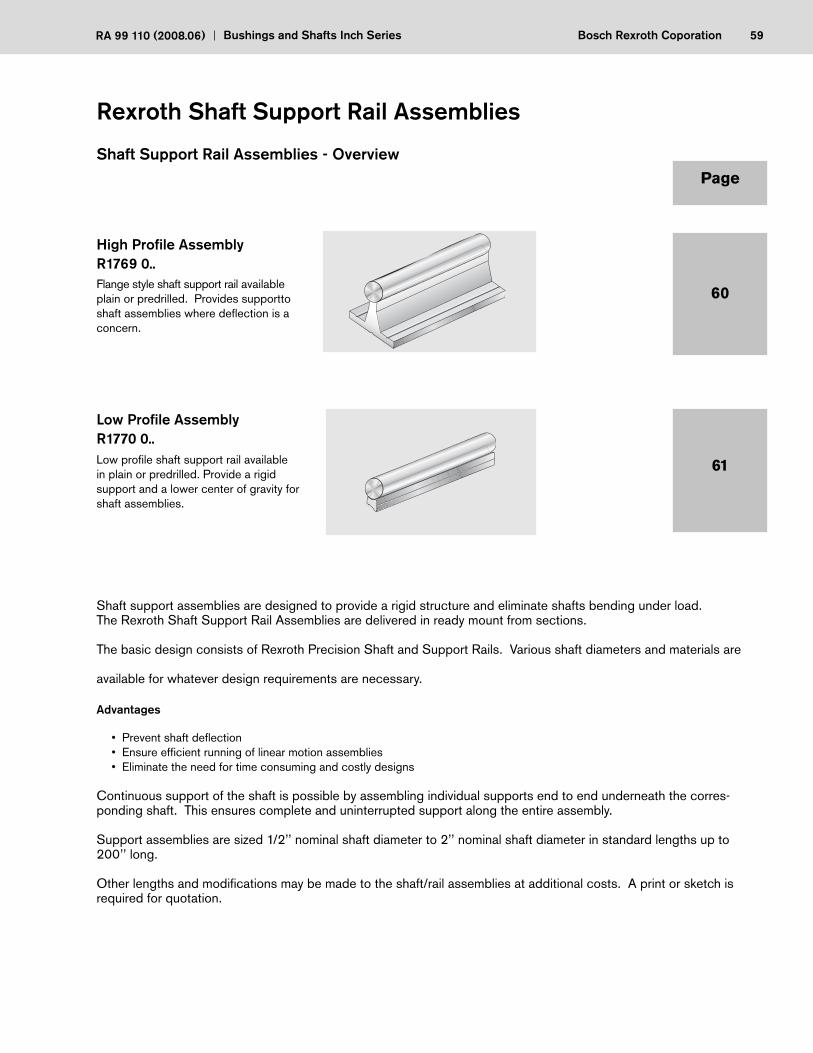
59Bosch Rexroth CoporationRA 99 110 (2008.06) Bushings and Shafts Inch Series
High Profi le AssemblyR1769 0..Flange style shaft support rail available plain or predrilled. Provides supportto shaft assemblies where defl ection is a concern.
Low Profi le AssemblyR1770 0..Low profi le shaft support rail available in plain or predrilled. Provide a rigid support and a lower center of gravity for shaft assemblies.
Rexroth Shaft Support Rail Assemblies
Page
60
61
Shaft Support Rail Assemblies - Overview
Shaft support assemblies are designed to provide a rigid structure and eliminate shafts bending under load. The Rexroth Shaft Support Rail Assemblies are delivered in ready mount from sections.
The basic design consists of Rexroth Precision Shaft and Support Rails. Various shaft diameters and materials are
available for whatever design requirements are necessary.
Advantages
• Prevent shaft defl ection • Ensure effi cient running of linear motion assemblies • Eliminate the need for time consuming and costly designs
Continuous support of the shaft is possible by assembling individual supports end to end underneath the corres-ponding shaft. This ensures complete and uninterrupted support along the entire assembly.
Support assemblies are sized 1/2’’ nominal shaft diameter to 2’’ nominal shaft diameter in standard lengths up to 200’’ long.
Other lengths and modifi cations may be made to the shaft/rail assemblies at additional costs. A print or sketch is required for quotation.
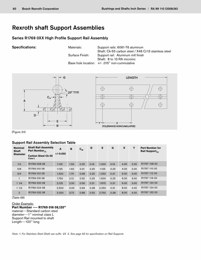
60 Bosch Rexroth Corporation Bushings and Shafts Inch Series RA 99 110 (2008.06)
Series R1769 0XX High Profi le Support Rail Assembly
Specifi cations: Materials: Support rails: 6061-T6 aluminum Shaft: Ck-55 carbon steel / X46 Cr13 stainless steel Surface Finish: Support rail: Aluminum mill fi nish Shaft: 8 to 13 RA microinc Base hole location: +/- .015’’ non-cummulative
Order Example:Part Number ---- R1769 016 08,120’’material----Standard carbon steeldiameter----1’’ nominal class LSupport Rail mounted to shaftLength----120’’ long
(Old Series 1700-6)
(Figure 24)
R1769 008 08
R1769 010 08
R1769 012 08
R1769 016 08
R1769 020 08
R1769 024 08
R1769 032 08
1.125
1.125
1.500
1.750
2.125
2.500
3.250
1.50
1.62
1.75
2.12
2.50
3.00
3.72
0.25
0.31
0.38
0.50
0.56
0.69
0.88
0.19
0.25
0.25
0.25
0.31
0.38
0.50
Nominal ShaftDiameter
Shaft Rail AssemblyPart Number(1)
Carbon Steel Ck-55Class L
B CW
Support Rail Assembly Selection TableD
1.000
1.125
1.250
1.500
1.875
2.250
2.750
0.19
0.25
0.31
0.25
0.31
0.31
0.38
E Part Number for Rail Support(2)
A
+/-0.002
1/2
5/8
3/4
1
1 1/4
1 1/2
2
G
(Table 68)
Note: 1. For Stainless Steel Shaft use suffi x -2X 2. See page 63 for specifi cation on Rail Supports
R1767 108 00
R1767 110 00
R1767 112 00
R1767 116 00
R1767 120 00
R1767 124 00
R1767 132 00
20° TYP.
G
C
D
A
EB
w
Rexroth shaft Support Assemblies
4.00
4.00
6.00
6.00
6.00
8.00
8.00
X
2.00
2.00
3.00
3.00
3.00
4.00
4.00
Y
LENGTHLENGTH
(TOLERANCE NONCUMULATIVE)(TOLERANCE NONCUMULATIVE)XY
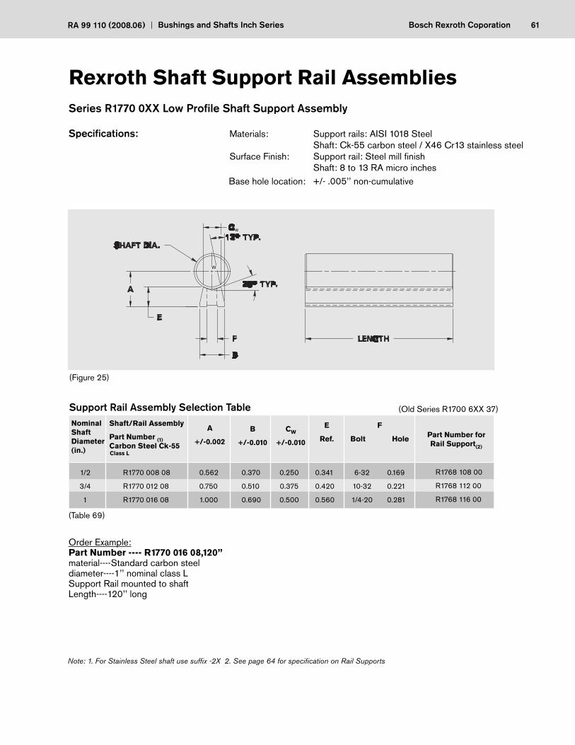
61Bosch Rexroth CoporationRA 99 110 (2008.06) Bushings and Shafts Inch Series
Series R1770 0XX Low Profi le Shaft Support Assembly
Specifi cations: Materials: Support rails: AISI 1018 Steel Shaft: Ck-55 carbon steel / X46 Cr13 stainless steel Surface Finish: Support rail: Steel mill fi nish Shaft: 8 to 13 RA micro inches Base hole location: +/- .005’’ non-cumulative
Order Example:Part Number ---- R1770 016 08,120’’material----Standard carbon steeldiameter----1’’ nominal class LSupport Rail mounted to shaftLength----120’’ long
Rexroth Shaft Support Rail Assemblies
(Figure 25)
(Table 69)
1/2
3/4
1
R1770 008 08
R1770 012 08
R1770 016 08
0.562
0.750
1.000
0.370
0.510
0.690
0.250
0.375
0.500
0.341
0.420
0.560
Nominal ShaftDiameter(in.)
Shaft/Rail Assembly
Part Number (1) Carbon Steel Ck-55 Class L
B
+/-0.010
CW
+/-0.010
Support Rail Assembly Selection Table
E
Ref.
6-32
10-32
1/4-20
0.169
0.221
0.281
R1768 108 00
R1768 112 00
R1768 116 00
F
Bolt Hole Part Number for Rail Support(2)
Note: 1. For Stainless Steel shaft use suffi x -2X 2. See page 64 for specifi cation on Rail Supports
A
+/-0.002
(Old Series R1700 6XX 37)
W
W
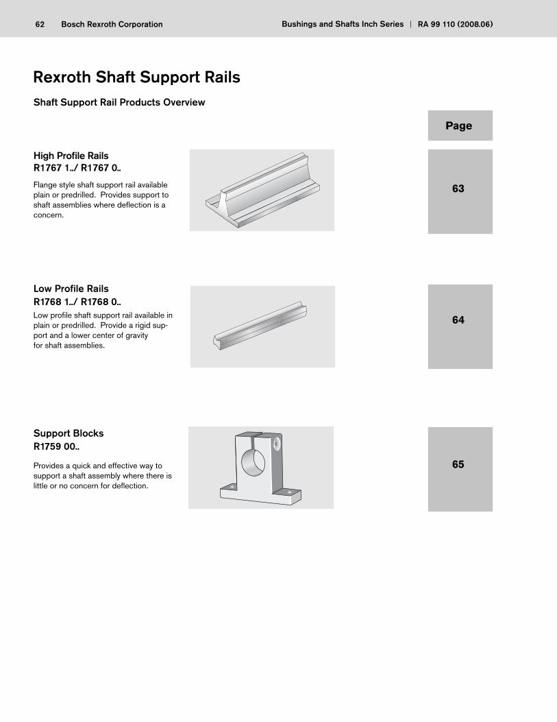
62 Bosch Rexroth Corporation Bushings and Shafts Inch Series RA 99 110 (2008.06)
High Profi le RailsR1767 1../ R1767 0..
Flange style shaft support rail available plain or predrilled. Provides support to shaft assemblies where defl ection is a concern.
Low Profi le RailsR1768 1../ R1768 0..Low profi le shaft support rail available in plain or predrilled. Provide a rigid sup-port and a lower center of gravityfor shaft assemblies.
Support BlocksR1759 00..
Provides a quick and effective way to support a shaft assembly where there is little or no concern for defl ection.
Rexroth Shaft Support Rails
63
64
65
Shaft Support Rail Products Overview
Page
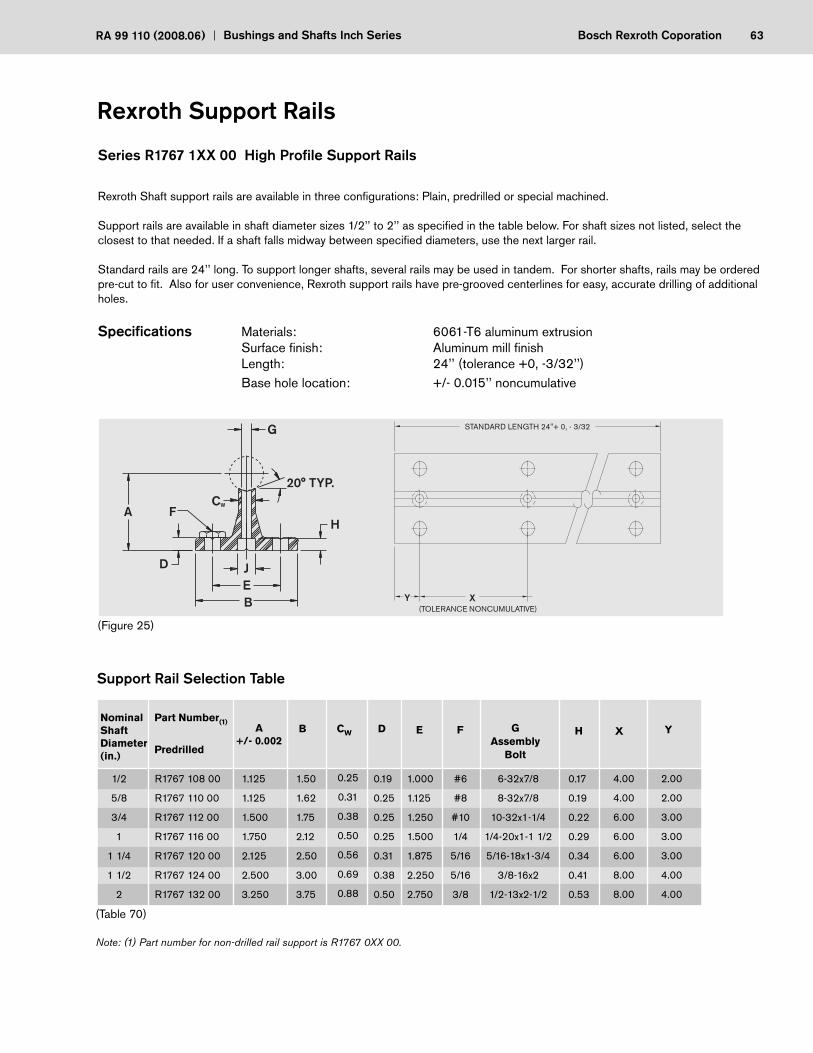
63Bosch Rexroth CoporationRA 99 110 (2008.06) Bushings and Shafts Inch Series
Rexroth Support Rails
1/2
5/8
3/4
1
1 1/4
1 1/2
2
R1767 108 00
R1767 110 00
R1767 112 00
R1767 116 00
R1767 120 00
R1767 124 00
R1767 132 00
1.125
1.125
1.500
1.750
2.125
2.500
3.250
1.50
1.62
1.75
2.12
2.50
3.00
3.75
0.25
0.31
0.38
0.50
0.56
0.69
0.88
0.19
0.25
0.25
0.25
0.31
0.38
0.50
Nominal ShaftDiameter(in.)
Part Number(1)
Predrilled
A+/- 0.002
B CW D
(Table 70)
Support Rail Selection Table
E
1.000
1.125
1.250
1.500
1.875
2.250
2.750
F
#6
#8
#10
1/4
5/16
5/16
3/8
GAssembly
Bolt
6-32x7/8
8-32x7/8
10-32x1-1/4
1/4-20x1-1 1/2
5/16-18x1-3/4
3/8-16x2
1/2-13x2-1/2
H
0.17
0.19
0.22
0.29
0.34
0.41
0.53
Note: (1) Part number for non-drilled rail support is R1767 0XX 00.
X Y
4.00 2.00
4.00 2.00
6.00 3.00
6.00 3.00
6.00 3.00
8.00 4.00
8.00 4.00
Series R1767 1XX 00 High Profi le Support Rails
Rexroth Shaft support rails are available in three confi gurations: Plain, predrilled or special machined.
Support rails are available in shaft diameter sizes 1/2’’ to 2’’ as specifi ed in the table below. For shaft sizes not listed, select the closest to that needed. If a shaft falls midway between specifi ed diameters, use the next larger rail.
Standard rails are 24’’ long. To support longer shafts, several rails may be used in tandem. For shorter shafts, rails may be ordered pre-cut to fi t. Also for user convenience, Rexroth support rails have pre-grooved centerlines for easy, accurate drilling of additional holes.
Specifi cations Materials: 6061-T6 aluminum extrusion Surface fi nish: Aluminum mill fi nish Length: 24’’ (tolerance +0, -3/32’’) Base hole location: +/- 0.015’’ noncumulative
(Figure 25)
STANDARD LENGTH 24"+ 0, - 3/32
(TOLERANCE NONCUMULATIVE)XY
G
20° TYP.
HA F
D JEB
CW
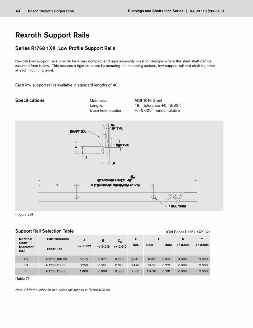
64 Bosch Rexroth Corporation Bushings and Shafts Inch Series RA 99 110 (2008.06)
Series R1768 1XX Low Profi le Support Rails
Rexroth Low support rails provide for a very compact and rigid assembly, ideal for designs where the steel shaft can be mounted from below. This ensures a rigid structure by securing the mounting surface, low support rail and shaft together at each mounting point.
Each low support rail is available in standard lengths of 48’’.
Specifi cations Materials: AISI 1018 Steel Length: 48’’ (tolerance +0, -3/32’’) Base hole location: +/- 0.005’’ noncumulative
(Table 71)
1/2
3/4
1
R1768 108 00
R1768 112 00
R1768 116 00
0.562
0.750
1.000
0.370
0.510
0.690
0.250
0.375
0.500
0.341
0.420
0.560
Nominal ShaftDiameter(in.)
Part Numbers
Predrilled
B
+/-0.010
CW
+/-0.010
Support Rail Selection Table
E
Ref.
6-32
10-32
1/4-20
0.169
0.221
0.281
4.000
6.000
6.000
F
Bolt Hole
X
+/-0.005
Y
+/-0.005
2.000
3.000
3.000
Note: (1) Part number for non-drilled rail support is R1768 0XX 00
A
+/-0.002
(Old Series R1767 XXX 37)
W
(Figure 26)
Rexroth Support Rails

65Bosch Rexroth CoporationRA 99 110 (2008.06) Bushings and Shafts Inch Series
Series R1759 XXX Support Blocks
Rexroth Series R1759 - Shaft Support Blocks may be used at end or intermediate positions on stationary shafts. They are ideal where loads are light and defl ections between supports pose no problem.
Supports must not interfere with bushing or carriage travel. Shimming is suggested for high precision applications to eliminate the effect of variations in base fl atness or support manufacturing tolerances. These blocks provide quick, fi rm clamping of shafts, reducing the need for specialized mountings and miscellaneous hardware.
Rexroth Support Blocks
1/2
3/4
1
1 1/4
1 1/2
2
R1759 008 01
R1759 012 01
R1759 016 01
R1759 020 01
R1759 024 01
R1759 032 01
1.00
1.25
1.50
1.75
2.00
2.50
2.00
2.50
3.06
3.75
4.38
5.50
0.63
0.75
1.00
1.13
1.25
1.50
1.63
2.13
2.56
3.00
3.50
4.50
Nominal ShaftDiameter(in.)
Part Number L N C O
Support Block Selection Table
D
1.50
2.00
2.50
3.00
3.50
4.50
A
0.25
0.31
0.38
0.44
0.50
0.63
P
0.88
1.25
1.50
2.00
2.25
3.00
Weight(lbs)
0.20
0.41
0.76
1.30
1.87
3.74
Nominal ShaftDiameter(in.)
1/2
3/4
1
1 1/4
1 1/2
2
Part Number H
Mounting Hole
Bolt Hole
#8
#10
1/4
5/16
5/16
3/8
3/16
7/32
9/32
11/32
11/32
13/32
R1759 008 01
R1759 012 01
R1759 016 01
R1759 020 01
R1759 024 01
R1759 032 01
(Table 72)
(Figure 27)
LL
CC
OO
DD
NN
PP
HH AA
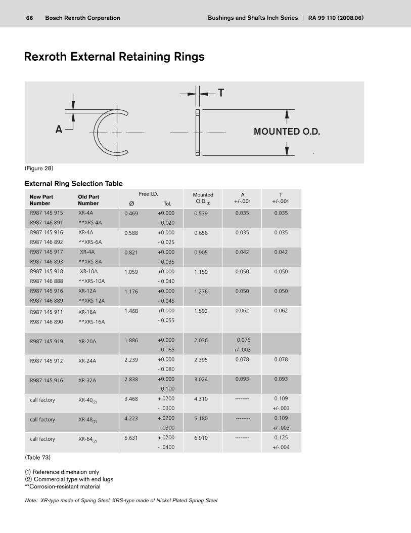
66 Bosch Rexroth Corporation Bushings and Shafts Inch Series RA 99 110 (2008.06)
(Table 73)
(1) Reference dimension only(2) Commercial type with end lugs**Corrosion-resistant material
Note: XR-type made of Spring Steel, XRS-type made of Nickel Plated Spring Steel
(Figure 28)
Free I.D.
Tol.
MountedO.D.(1)
A+/-.001
T+/-.001
R987 145 915 XR-4A
R987 146 891 **XRS-4A
R987 145 916 XR-4A
R987 146 892 **XRS-6A
R987 145 917 XR-4A
R987 146 893 **XRS-8A
R987 145 918 XR-10A
R987 146 888 **XRS-10A
R987 145 916 XR-12A
R987 146 889 **XRS-12A
R987 145 911 XR-16A
R987 146 890 **XRS-16A
R987 145 919 XR-20A
R987 145 912 XR-24A
R987 145 916 XR-32A
call factory XR-40(2)
call factory XR-48(2)
call factory XR-64(2)
0.469
0.588
0.821
1.059
1.176
1.468
1.886
2.239
2.838
3.468
4.223
5.631
+0.000
- 0.020
+0.000
- 0.025
+0.000
- 0.035
+0.000
- 0.040
+0.000
- 0.045
+0.000
- 0.055
+0.000
- 0.065
+0.000
- 0.080
+0.000
- 0.100
+.0200
- .0300
+.0200
- .0300
+.0200
- .0400
0.539
0.658
0.905
1.159
1.276
1.592
2.036
2.395
3.024
4.310
5.180
6.910
0.035
0.035
0.042
0.050
0.050
0.062
0.075
+/-.002
0.078
0.093
--------
--------
--------
0.035
0.035
0.042
0.050
0.050
0.062
0.078
0.093
0.109
+/-.003
0.109
+/-.003
0.125
+/-.004
External Ring Selection Table
Rexroth External Retaining Rings
MOUNTED O.D.A
T
ØNew Part Old Part Number Number

67Bosch Rexroth CoporationRA 99 110 (2008.06) Bushings and Shafts Inch Series
Notes
Bosch Rexroth CorporationCorporate Headquarters5150 Prairie Stone ParkwayHoffman Estates, IL 60192-3707Telephone (847) 645-3600Facsimile (847) 645-6201
Bosch Rexroth CorporationIndustrial Hydraulics2315 City Line RoadBethlehem, PA 18017-2131Telephone (610) 694-8300Facsimile (610) 694-8467
Bosch Rexroth CorporationElectric Drives and Controls5150 Prairie Stone ParkwayHoffman Estates, IL 60192-3707Telephone (847) 645-3600Facsimile (847) 645-6201
Bosch Rexroth CorporationPneumatics1953 Mercer RoadLexington, KY 40511-1021Telephone (859) 254-8031Facsimile (859) 281-3491
Bosch Rexroth CorporationMobile Hydraulics1700 Old Mansfield RoadWooster, OH 44691-0394Telephone (330) 263-3300Facsimile (330) 263-3333
Printed in the United States RA 99 110
Bosch Rexroth CorporationLinear Motion andAssembly Technologies14001 South Lakes DriveCharlotte, NC 28273Telephone (800) 438-5983Facsimile (704) 583-0523www.boschrexroth-us.com