linear drain installation guide - bronte™ collection
TRANSCRIPT
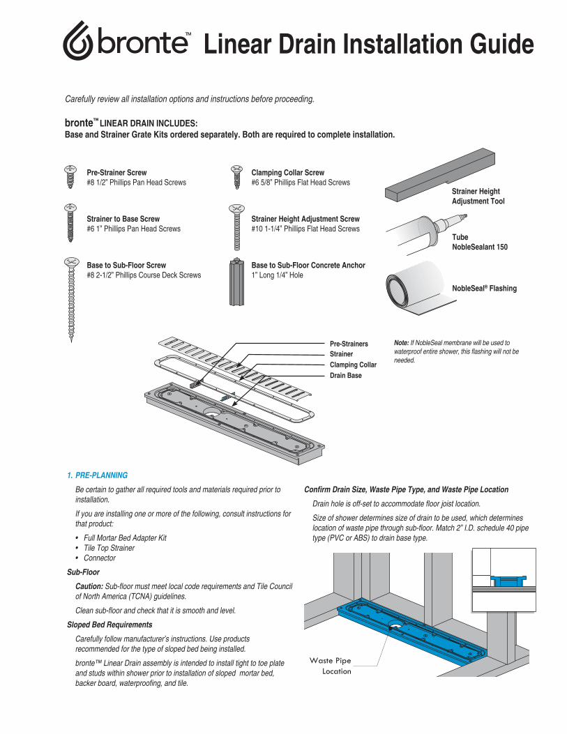
Carefully review all installation options and instructions before proceeding.
bronte™ LINEAR DRAIN INCLUDES:Base and Strainer Grate Kits ordered separately. Both are required to complete installation.
Linear Drain Installation Guide
Note: If NobleSeal membrane will be used to waterproof entire shower, this flashing will not be needed.
Pre-Strainer Screw#8 1/2” Phillips Pan Head Screws
Clamping Collar Screw#6 5/8” Phillips Flat Head Screws
Strainer Height Adjustment Tool
Tube NobleSealant 150
NobleSeal® Flashing
Strainer to Base Screw#6 1” Phillips Pan Head Screws
Strainer Height Adjustment Screw#10 1-1/4” Phillips Flat Head Screws
Base to Sub-Floor Screw#8 2-1/2” Phillips Course Deck Screws
Base to Sub-Floor Concrete Anchor1” Long 1/4” Hole
Pre-StrainersStrainerClamping CollarDrain Base
1. PRE-PLANNING
Be certain to gather all required tools and materials required prior to installation.
If you are installing one or more of the following, consult instructions for that product:
• Full Mortar Bed Adapter Kit• Tile Top Strainer• Connector
Sub-Floor
Caution: Sub-floor must meet local code requirements and Tile Council of North America (TCNA) guidelines.
Clean sub-floor and check that it is smooth and level.
Sloped Bed Requirements
Carefully follow manufacturer’s instructions. Use products recommended for the type of sloped bed being installed.
bronte™ Linear Drain assembly is intended to install tight to toe plate and studs within shower prior to installation of sloped mortar bed, backer board, waterproofing, and tile.
Confirm Drain Size, Waste Pipe Type, and Waste Pipe Location
Drain hole is off-set to accommodate floor joist location.
Size of shower determines size of drain to be used, which determines location of waste pipe through sub-floor. Match 2” I.D. schedule 40 pipe type (PVC or ABS) to drain base type.
2 bronte™ Linear Drain Installation Guide
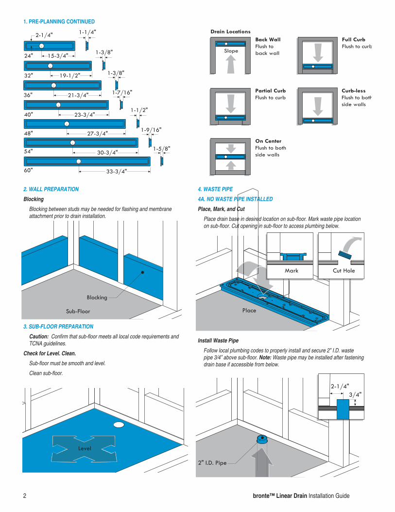
2. WALL PREPARATION
Blocking
Blocking between studs may be needed for flashing and membrane attachment prior to drain installation.
3. SUB-FLOOR PREPARATION
Caution: Confirm that sub-floor meets all local code requirements and TCNA guidelines.
Check for Level. Clean.
Sub-floor must be smooth and level.
Clean sub-floor.
4. WASTE PIPE
4A. NO WASTE PIPE INSTALLED
Place, Mark, and Cut
Place drain base in desired location on sub-floor. Mark waste pipe location on sub-floor. Cut opening in sub-floor to access plumbing below.
Install Waste Pipe
Follow local plumbing codes to properly install and secure 2” I.D. waste pipe 3/4” above sub-floor. Note: Waste pipe may be installed after fastening drain base if accessible from below.
1. PRE-PLANNING CONTINUED
bronte™ Linear Drain Installation Guide 3
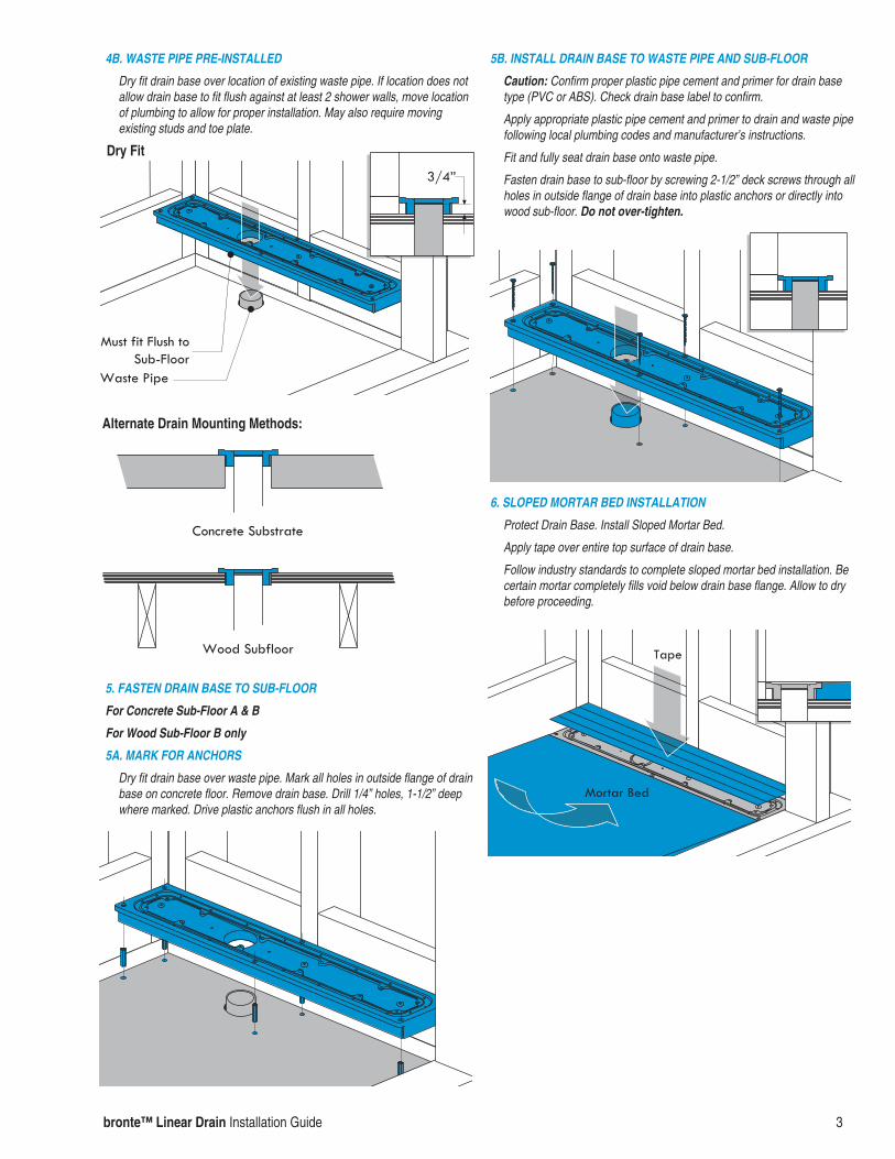
4B. WASTE PIPE PRE-INSTALLED
Dry fit drain base over location of existing waste pipe. If location does not allow drain base to fit flush against at least 2 shower walls, move location of plumbing to allow for proper installation. May also require moving existing studs and toe plate.
5. FASTEN DRAIN BASE TO SUB-FLOOR
For Concrete Sub-Floor A & B
For Wood Sub-Floor B only
5A. MARK FOR ANCHORS
Dry fit drain base over waste pipe. Mark all holes in outside flange of drain base on concrete floor. Remove drain base. Drill 1/4” holes, 1-1/2” deep where marked. Drive plastic anchors flush in all holes.
5B. INSTALL DRAIN BASE TO WASTE PIPE AND SUB-FLOOR
Caution: Confirm proper plastic pipe cement and primer for drain base type (PVC or ABS). Check drain base label to confirm.
Apply appropriate plastic pipe cement and primer to drain and waste pipe following local plumbing codes and manufacturer’s instructions.
Fit and fully seat drain base onto waste pipe.
Fasten drain base to sub-floor by screwing 2-1/2” deck screws through all holes in outside flange of drain base into plastic anchors or directly into wood sub-floor. Do not over-tighten.
6. SLOPED MORTAR BED INSTALLATION
Protect Drain Base. Install Sloped Mortar Bed.
Apply tape over entire top surface of drain base.
Follow industry standards to complete sloped mortar bed installation. Be certain mortar completely fills void below drain base flange. Allow to dry before proceeding.
Dry Fit
Alternate Drain Mounting Methods:

4 bronte™ Linear Drain Installation Guide
MAKING CORNERS - See Prepare Flashing Below
Tucked Corner (when space is available between studs)
Fold and crease to size. Tuck flashing into space between studs.
Folded Corner
Fold and crease to size. Fold corners behind flashing.
7. PREPARE FLASHING
Flashing must turn up the walls a minimum of 3” above shower curb and 6” above floor in showers without curbs.
Measure width of shower floor across drain base. Lay flashing flat. Measure and mark flashing.
Fold and crease for upturns and create corners. Note: Do not secure flashing at this time.
7. PREPARE FLASHING CONTINUED
Flashing must turn up the walls a minimum of 3” above shower curb and 6” above floor in showers without curbs.
Prior to installing flashing, install pre-formed outside corners available separately from bronte™ following manufacturer’s instructions. 2 per side.
Measure width of shower floor across drain base. Measure up and over curb. Lay flashing flat. Measure and mark flashing.
Cut, fold, and crease to proper size and fit. Note: Do not secure flashing at this time.
Note: bronte™ Curb may also be used. See manufacturer’s instructions.
Drain at Back Wall
Drain at Full Curb Entry
Inside Shower Outside Shower

bronte™ Linear Drain Installation Guide 5
7. PREPARE FLASHING CONTINUED
Flashing must turn up the walls a minimum of 3” above shower curb and 6” above floor in showers without curbs.
Prior to installing flashing, install pre-formed outside corners available separately from bronte™ following manufacturer’s instructions. 2 per side.
Measure width of shower floor across drain base. Measure up and over curb. Lay flashing flat. Measure and mark flashing.
Cut, fold, and crease to proper size and fit. Note: Do not secure flashing at this time.
Note: bronte™ Curb may also be used. See manufacturer’s instructions.
7. PREPARE FLASHING CONTINUED
Flashing must turn up the walls a minimum of 3” above shower curb and 6” above floor in showers without curbs.
Measure width of shower floor across drain base.
Lay flashing flat. Measure and mark flashing.
Cut, fold, and crease to proper size and fit. Note: Do not secure flashing at this time.
Flashing must turn up the walls a minimum of 3” above shower curb and 6” above floor in showers without curbs.
Measure width of shower floor across drain base.
Lay flashing flat. Measure and mark flashing.
Fold and crease for upturns. Note: Do not secure flashing at this time.
Drain at Partial Width Curb
Inside Shower Outside Shower
Drain at Curb-less Entry
Inside Shower Outside Shower
Drain On Center

6 bronte™ Linear Drain Installation Guide
8. SECURE FLASHING
8A. SEAL DRAIN BASE
Lift out flashing. Remove tape, leaving tape over drain hole only.
Apply a 1/8” continuous bead of NobleSealant 150 around chamfer on base flange and another bead in groove on drain base.
8B. APPLY ADHESIVES
Apply NobleBond EXT or modified thin-set to mortar bed, walls, and curb as needed. Apply NobleSealant 150 to any pre-formed corners.
8C. PRESS INTO SEALANT AND ADHESIVE
Align membrane and firmly press all areas of membrane into adhesive on walls, floor, curb and sealant on drain base and any pre-formed corners.
9. FASTEN FLASHING
Nail through top 1” of flashing to studs and/or blocking.
10. INSTALL CLAMPING COLLAR
Align collar with drain base under flashing. Press firmly.
Starting at one end, insert 5/8” screw through collar, punch through flashing, and screw into base. Repeat for all screws. Do not over-tighten.
11. CUT OUT FLASHING
With a razor knife, carefully trim out flashing from center of collar. Remove tape from drain hole. Caution: Do not puncture flashing outside of collar.
bronte™ Linear Drain Installation Guide 7
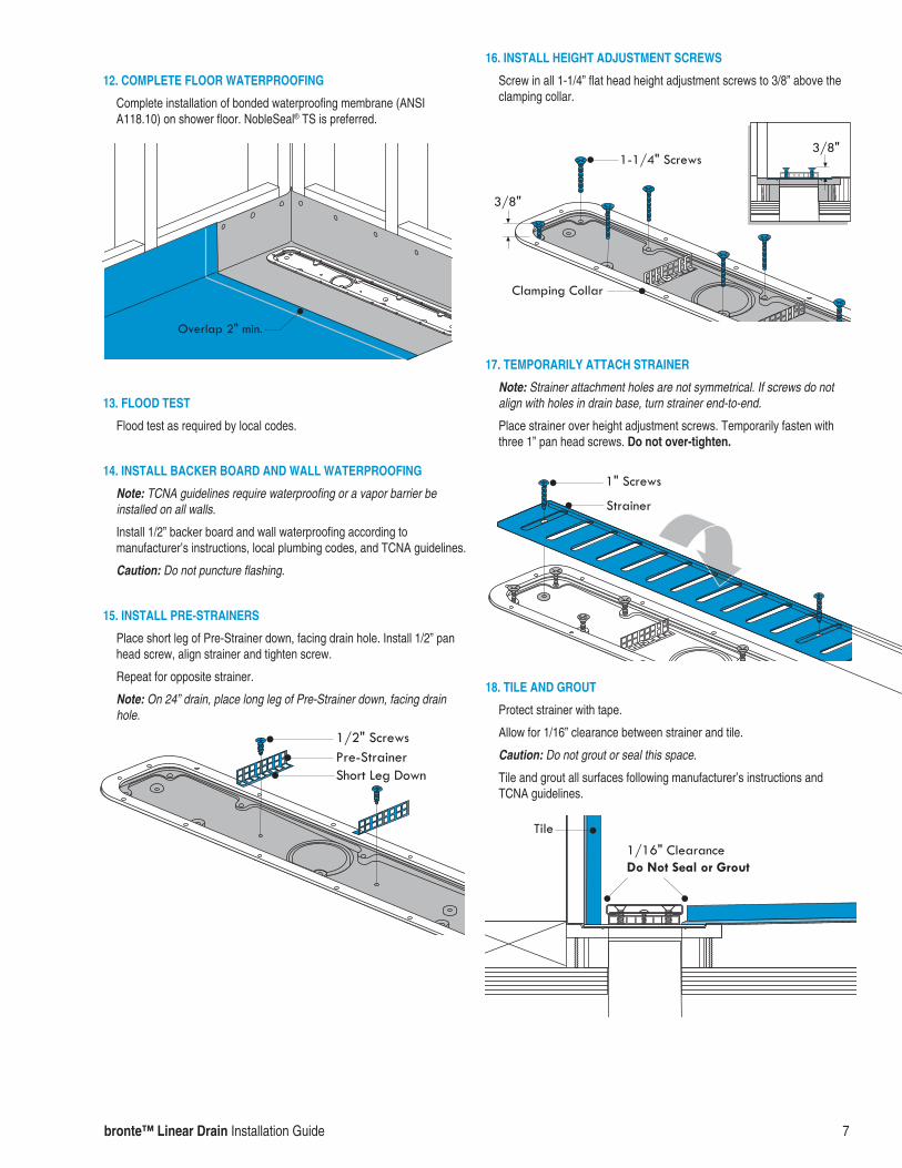
12. COMPLETE FLOOR WATERPROOFING
Complete installation of bonded waterproofing membrane (ANSI A118.10) on shower floor. NobleSeal® TS is preferred.
13. FLOOD TEST
Flood test as required by local codes.
14. INSTALL BACKER BOARD AND WALL WATERPROOFING
Note: TCNA guidelines require waterproofing or a vapor barrier be installed on all walls.
Install 1/2” backer board and wall waterproofing according to manufacturer’s instructions, local plumbing codes, and TCNA guidelines.
Caution: Do not puncture flashing.
15. INSTALL PRE-STRAINERS
Place short leg of Pre-Strainer down, facing drain hole. Install 1/2” pan head screw, align strainer and tighten screw.
Repeat for opposite strainer.
Note: On 24” drain, place long leg of Pre-Strainer down, facing drain hole.
16. INSTALL HEIGHT ADJUSTMENT SCREWS
Screw in all 1-1/4” flat head height adjustment screws to 3/8” above the clamping collar.
17. TEMPORARILY ATTACH STRAINER
Note: Strainer attachment holes are not symmetrical. If screws do not align with holes in drain base, turn strainer end-to-end.
Place strainer over height adjustment screws. Temporarily fasten with three 1” pan head screws. Do not over-tighten.
18. TILE AND GROUT
Protect strainer with tape.
Allow for 1/16” clearance between strainer and tile.
Caution: Do not grout or seal this space.
Tile and grout all surfaces following manufacturer’s instructions and TCNA guidelines.
® NobleSeal is a Registered Trademark of Noble Company | ® ValueSeal is a Registered Trademark of Noble Company, Grand Haven, MI. bronte™ is a Trademark of Oakville Stamping & Bending Ltd.
File #FM-LDIM2 | 09/16 | Supersedes FM-LDIM
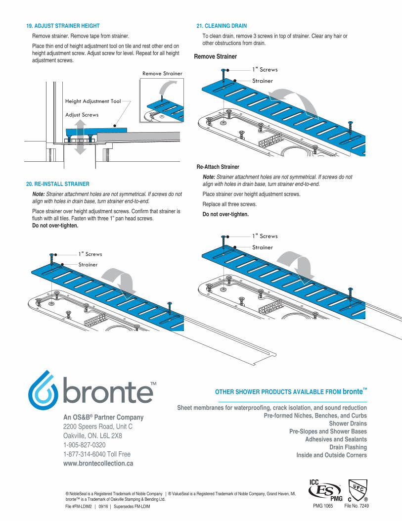
19. ADJUST STRAINER HEIGHT
Remove strainer. Remove tape from strainer.
Place thin end of height adjustment tool on tile and rest other end on height adjustment screw. Adjust screw for level. Repeat for all height adjustment screws.
20. RE-INSTALL STRAINER
Note: Strainer attachment holes are not symmetrical. If screws do not align with holes in drain base, turn strainer end-to-end.
Place strainer over height adjustment screws. Confirm that strainer is flush with all tiles. Fasten with three 1” pan head screws. Do not over-tighten.
21. CLEANING DRAIN
To clean drain, remove 3 screws in top of strainer. Clear any hair or other obstructions from drain.
Re-Attach Strainer
Note: Strainer attachment holes are not symmetrical. If screws do not align with holes in drain base, turn strainer end-to-end.
Place strainer over height adjustment screws.
Replace all three screws.
Do not over-tighten.
Remove Strainer
PMG 1065 File No. 7249
OTHER SHOWER PRODUCTS AVAILABLE FROM bronte™
Sheet membranes for waterproofing, crack isolation, and sound reductionPre-formed Niches, Benches, and Curbs
Shower DrainsPre-Slopes and Shower Bases
Adhesives and SealantsDrain Flashing
Inside and Outside Corners
An OS&B® Partner Company2200 Speers Road, Unit COakville, ON. L6L 2X81-905-827-03201-877-314-6040 Toll Freewww.brontecollection.ca