linear guideways - monguzzisrl.eu vdi 2230.; formula 1.1 f sl = static structural safety for simple...
TRANSCRIPT

Linear Guideways
www.hiwin.de

HIWIN GmbHBrücklesbünd 2D-77654 OffenburgPhone +49 (0) 7 81 9 32 78 - 0Fax +49 (0) 7 81 9 32 78 - [email protected]
All rights reserved.Complete or partial reproduction is not permitted without our permission.
Note:The technical data in this catalog may be changed without prior notice.

Welcome to HIWIN A linear guideway permits linear movement with the aidof rolling elements. By using balls or rollers between therail and block, a linear guideway can attain an extremelyprecise linear movement. Compared with a standardsliding guide, the friction coefficient here is just onefiftieth. The good efficiency and zero play mean that thelinear guideway can be used in various ways.

Linear guideways

General information
1.1 Properties and advantages 61.2 Selection principles 71.3 Load ratings 81.4 Lifetime calculation 91.5 Operating load 111.6 Friction and lubrication 131.7 Mounting position 141.8 Assembly 151.9 Sealing systems 201.10 SynchMotion™ technology 221.11 Heat-resistant linear guideways 23
1. 6
Linear guideways
2.1 Product overview 242.2 Linear guideway, series HG and QH 262.3 Linear guideway, series EG and QE 442.4 Linear guideway, series WE 602.5 Linear guideway, series MG 722.6 Linear guideway, series PM 852.7 Linear guideway, series RG and QR 942.8 Linear guideway, series PG 1102.9 Accessories 117
2. 24
Contents

1. General information
1.1 Properties and advantages
1.1.1 Properties and advantages of linear guideways
1. High positioning accuracy
A carriage mounted with a linear guideway only has to overcome rolling friction. The
difference between the static and dynamic rolling friction is very small so the break-
away force is only slightly greater than the motion force. Stick-slip effects are not
experienced.
2. Long lifetime and highly precise movement
With a sliding guide, the different thicknesses of lubrication film may result in accu-
racy errors. The sliding friction and the fact that lubrication is often insufficient cause
a lot of wear and therefore decreasing accuracy. Contrasted with this, the linear guide-
way has very low rolling friction, coupled with extremely low wear. Guidance accuracy
remains virtually constant over the entire lifetime.
3. High speed and low driving force
The low friction coefficients mean that only low driving forces are needed. The required
power also remains low when reversing.
4. Same high load capacity in all directions
Thanks to the enforced guidance inherent in its design, a linear guideway can absorb
forces in a vertical and horizontal direction.
5. Simple installation and interchangeability
Assembling a linear guideway is a simple process. A high level of accuracy is achieved
with a milled or ground mounting surface if the assembly instructions are followed.
Standard sliding guides require considerably more effort to assemble as the sliding
surfaces have to be scraped. Individual components cannot be interchanged without
scraping. Linear guideways can however be interchanged with very little effort.
6. Simple lubrication
Insufficient lubrication on sliding guides destroys the sliding surfaces. Lubricant must
be used at a large number of points on the sliding surfaces. The linear guideway only
requires minimal lubrication which is provided by a simple supply line to the block.
HIWIN can also supply blocks with an integrated oil lubrication unit and interchange-
able oil tank for long-term lubrication.
7. Corrosion protection
To achieve optimum corrosion protection, blocks and rails can be supplied with differ-
ent coatings. The individual procedures selected depend on the application. Data relat-
ing to the ambient conditions and corrosive substances is needed for an optimum
choice of coating. The miniature linear guideways MG and PM are produced in stainless
steel.
General informationProperties and advantages
6

1.2 Selection principles
1.2.1 Selection principles for a linear guideway
Establish the selection conditions
Machine base Travel distance
Max. installation space Speed of travel, acceleration
Desired accuracy Frequency of use
Rigidity required Lifetime
Type of loading Ambient conditions
Select the series
HG series – Grinding, milling and drilling machines, lathes, machining centres
EG series – Automation technology, high-speed transport, semiconductor equipment,
woodworking, precision measuring equipment
MG/PM series – Miniature technology, semiconductor equipment, medical technology
RG series – Machining centres, injection moulding machines, machines and systems with high rigidity
Select the accuracy class
Classes C, H, P, SP, UP depending on the accuracy required
Define the size and number of blocks
Depending on empirical values
Depending on type of loading
If a ballscrew is used, the nominal size of the linear guideways and the ballscrew should be roughly
the same, e.g. 32 ballscrew and 35 rail
Calculate the maximum load of the blocks
Calculate the maximum load using the sample calculations Ensure that the static structural safety of the
selected linear guideway is higher than the corresponding value in the table on static structural safety
Determine the preload
The preload depends on the rigidity requirements and the accuracy of the mounting surface
Determine the rigidity
Use the rigidity table to calculate the deformation (d); the rigidity increases with preload and as
the guide increases in size
Calculate the lifetime
Establish the lifetime needed taking account of the speed and frequency of travel; base work on
sample calculations
Select the type of lubrication
Grease via grease nipple
Oil via connection line
Selection complete
→
→
←
←
←
→→
→→
→→
→→
→
→
7

1.3 Load ratings
1.3.1 Static load rating C0
If a linear guideway is subject to disproportionately high loads or impact during move-
ment or when stationary, local permanent deformation occurs between the block and
balls. Once this permanent deformation exceeds a particular level, it impacts on how
easily the guide moves. By definition, the static load rating corresponds to a static load
which causes a permanent deformation of 0.0001 × ball diameter at the point of
contact subject to the most loading. The values are stated in the tables for each linear
guideway. These tables can be used to select a suitable linear guideway. The maximum
static load to which a linear guideway is subjected must not exceed the static load
rating.
1.3.2 Permissible static moment M0
The permissible static moment is the moment that corresponds to the greatest
possible loading of moving parts by the static load rating in a defined direction and
magnitude. The permissible static moment is defined in three directions (MX, MY and
MZ) for linear movement systems.
MX MY MZ
1.3.3 Static structural safety
Static structural safety, which depends on the ambient and operating conditions, must
be taken into account for rail systems at rest or moving slowly. A higher level of struc-
tural safety is especially important for guides subject to impact loads, see Table 1.1.
The static structural safety can be calculated using Formula 1.1.
Please note: The load-bearing capacity of the linear guideway is often limited not by
its load-bearing strength, but the screw connection. We therefore recommend checking
the maximum permitted load-bearing capacity of the screw connection in accordance
with VDI 2230.
;
Formula 1.1
fSL = Static structural safety for simple loading
fSM = Static safety factor for torque loading
C0 = Static load rating [N]
M0 = Permissible static moment [Nm]
P = Equivalent static working load [N]
M = Equivalent static moment [Nm]
Table 1.1 Static structural safety
Loading fSL – fSM [min.]Normal loading 1,25 – 3,00
With impact and vibration 3,00 – 5,00
1.3.4 Dynamic load rating Cdyn
The dynamic load rating is the defined loading (in direction and magnitude) at which a
linear guideway achieves a nominal lifetime of 50 km 1) travel distance (HG, QH, EG, QE,
WE, MG, TM) or 100 km 1) (RG). The dynamic load rating is stated for each guide in the
dimension charts. This can be used to calculate the lifetime of one particular guide.
1) Note
The dynamic load rating of linear guideways is stated for a lifetime of 50 or 100 km
travel distance depending on the manufacturer. The following factors can be used to
convert the dynamic load rating.
Cdyn 50 km = 1.26 × Cdyn 100 km (series HG, QH, EG, QE, WE, MG, TM)
Cdyn 50 km = 1.23 × Cdyn 100 km (series RG)
General informationLoad ratings
8

1.4 Lifetime calculation
1.4.1 Definition of lifetime
Continual and repeat loading of the tracks and balls on a linear guideway causes signs
of fatigue on the track surface. Ultimately this results in what is known as pitting.
The lifetime of a linear guideway is defined as the total travel distance covered until
pitting starts to form on the surface of the track or balls.
1.4.2 Nominal lifetime (L)
The lifetime may vary significantly even if the linear guideways are produced in the
same way and used under the same movement conditions. The nominal lifetime should
therefore be viewed as a rough estimate of the lifetime of a linear guideway.
The nominal lifetime corresponds to the total travel distance which 90 % of a group of
identical linear guideways reach under the same conditions without failure.
1.4.2.1 Nominal lifetime calculation
The actual loading affects the nominal lifetime of a linear guideway. The nominal
lifetime can be calculated with Formulas 1.2.1 and 1.2.2 using the selected dynamic
load rating and equivalent dynamic loading.
Table 1.2 Formulas for calculating nominal lifetime (L)
Formel1 Formel2 Symbole50km dyn L = Nominal lifetime [km]
Cdyn = Dynamic load rating [N]
P = Equivalent dynamic loading [N]Formula 1.2.1 (series HG, QH, EG, QE, WE, MG, PM) Formula 1.2.2 (series RG, QR)
1.4.2.2 Factors affecting nominal lifetime
The type of loading, hardness of the track and temperature of the guide have a
considerable impact on the nominal lifetime. Formulas 1.3.1 and 1.3.2 show the
relationship between these factors.
Hardness factor (fh)
The tracks of the linear guideways have a hardness of 58 HRC. A hardness factor of
1.0 applies. If the hardness differs from this, the hardness factor shown on the right
should be used. If the stated hardness is not reached, the permissible loading is
reduced. If this happens, the dynamic and static load ratings must be multiplied by the
hardness factor.
Temperature factor (ft)
Standard rails can be used in an ambient temperature range of –10 to 80 °C. At
ambient temperatures up to 150 °C, linear guideways with a metallic end cap must be
used (identified in the type code by the addition “/SE”). Intermittent ambient tempera-
tures of up to 180 °C are possible. However, we do recommend contacting our techni-
cal support team to be sure. If the temperature of a linear guideway exceeds 100 °C,
the permissible load and lifetime are reduced. The dynamic and static load ratings
must therefore be multiplied by the temperature factor.
9

Load factor (fw)
The loads affecting a linear guideway include the weight of the block, the inertia at the
start and end of movements and load torques which are caused by the projection of the
load. These load factors are particularly hard to estimate when accompanied by vibra-
tion or impact load. The load should therefore be multiplied by the empirical load fac-
tor. The load factor calculated should be doubled for short-stroke applications (stroke
= 2 × block length).
Table 1.3 Load factor
Type of loading Speed of travel fw
No impact and vibration up to 15 m/min 1,0 – 1,2
Normal load 15 m/min to 60 m/min 1,2 – 1,5
Little impact 60 m/min to 120 m/min 1,5 – 2,0
With impact and vibration greater than 120 m/min 2,0 – 3,5
Table 1.4 Formula for calculating nominal lifetime (taking factors into account)
Formel1 Formel2 Symbole
50 km dyn
L = Nominal lifetime [km]
fh = Hardness factor
Cdyn = Dynamic load rating [N]
ft = Temperature factor
P = Equivalent dynamic loading [N]
fW = Load factorFormula 1.3.1 (series HG, QH, EG, QE, WE, MG, PM) Formula 1.3.2 (series RG, QR)
1.4.3 Lifetime calculation (Lh)
The speed of travel and frequency of movement are used to calculate the lifetime in
hours from the nominal lifetime.
Table 1.5 Formula for calculating lifetime (Lh)
Formel1 Formel2 Symbole100.000
10Lh: Lifetime [h]
L: Nominal lifetime [m]
v: Speed [m/min]
C/P: Ratio between load rating and loadFormula 1.4.1 (series HG, QH, EG, QE, WE, MG, PM) Formula 1.4.2 (series RG, QR)
General informationLifetime calculation
10

1.5 Operating load
1.5.1 Operating load
When calculating the loads acting on a linear guideway, various factors must be taken
into account, e.g. the focal point of the load, the motion force's point of entry and the
mass inertia at the start and end of movement. To obtain a correct value, each para-
meter must be taken into account.
Table 1.6 Load on a block (examples of calculating load on a block)
Typical examples Distribution of load Load on a block
F P2
P4
P3
P1
FF
1 2
3 4
F
W W
W
FA
c/2c
b
a
dc/2 d/2d/2
FP2
P4P3
P1
FF
1 2
3 4
F
W W
W
FA
c/2c dc/2 d/2d/2
F
P2
P4
P3
P1 F
h
F
1
2
3
4
W W
FA
c/2c
d
c/2
d/2
d/2
FP2
Pt2
P4
Pt4
P3
Pt3
P1Pt1
F
k
h
F1 2
3 4
W WFA
c/2
c
d
c/2
d/2d/2
P1...P4: Load on the individual block
W: Weight of load
F: Motion force; other force arising
FA: Reaction force
11

1.5.1.1 Load and mass inertia
Table 1.7 Load and mass inertia (examples of calculating load and mass inertia)
Spalte 1 Spalte 2
1 2
3 4
W
W W
FA
FA
VC [m/s]
t [s]
c d
t1 t2 t3
c/2c/2 d/2 d/2
P1...P4: Load on the individual block [N]
F: Motion force [N]
W: Weight of load [N]
g: Acceleration of gravity [m/s2]
Vc: Speed [m/s]
Fa: Reaction force
Table 1.8 Load and mass inertia (examples of calculating load and mass inertia)
Constant speed Acceleration Deceleration
1.5.2 Calculation of equivalent load during changing loads
If loading of a linear guideway fluctuates greatly, an equivalent load must be used in
the lifetime calculation. The equivalent load is defined as the load which causes the
same wear on the bearings as the changing loads. It can be calculated using Table 1.9.
Pm: Equivalent load
Pn: Changing load
Pmin: Minimum load
Pmax: Maximum load
L: Total travel distance
Ln: Travel distance under load
Table 1.9 Examples of calculating equivalent load (Pm)
Gradual change Steady change Sinusoidal change
P P1
L1 L2 Ln
L
P2
Pm
Pn
P
L
Pmax
Pmin
Pm
P
L
Pmax
Pm
General informationOperating load
12

1.6 Friction and lubrication
1.6.1 Frictional resistance
Using rolling elements in the linear guideway mainly reduces friction on the roll
friction of the rolling elements. This makes the friction coefficient of linear guideways
very low, up to one fiftieth of that of traditional sliding guides. Generally, the friction
coefficient is around 0.004 depending on the series. If the loading is only 10 % or less
of the dynamic load rating, most of the frictional resistance is caused by the wiper and
grease and friction between the rolling elements. If the operating load is more than
10 % of the dynamic load rating, the load provides the majority of the frictional
resistance.
Formula 1.5
F: Frictional force [N]
S: Frictional resistance [N]
µ: Friction coefficient
W: Load [N]
1.6.2 Lubrication
Like any other roller bearing, linear guideways need a sufficient supply of lubricant. In
principle, both oil and grease can be used for lubrication. The lubricant is a design
element and should be taken into account when designing a machine.
HIWIN provides greases for various requirements:
○�HIWIN G01 heavy-duty applications
○�HIWIN G02 clean room and vacuum applications
○�HIWIN G03 high-speed clean room and vacuum applications
○�HIWIN G04 high-speed applications
○�HIWIN G05 standard applications
Lubricants reduce wear, protect against contamination, reduce corrosion and their
properties extend the service life. Dirt may build up on unprotected rails. This dirt must
be removed on a regular basis.
You will find information about the HIWIN lubricants in the accessories chapter on page
121. You will also find details about the HIWIN lubricants and lubrication of the linear
guideways in the “HIWIN assembly instructions for linear guideways” available
from www.hiwin.de.
1.6.3 Oil lubrication unit E2
The oil lubrication unit E2 consists of a lubricating unit between the deflection system
and the end seal, and an interchangeable oil tank. The block does not need to be
disassembled in order to interchange the oil tank. Lubrication passes from the oil tank
via the connector to the lubricating unit which then lubricates the track of the rail. Due
to the specific design of the oil tank, the block can be assembled in any position with-
The oil lubrication unit E2 is available for the HG, EG and RG series. You will find the
corresponding dimensions, lubricant volumes and intervals in the chapters for the
corresponding series. Series HG page 39, series EG page 56, series RG page 105.
out influencing the lubrication effect. The oil lubrication unit E2 can be used at an
ambient temperature of –10 °C to +60 °C. The replacement intervals depend greatly
on the loads and the environmental conditions. Environmental influences such as high
loads, vibrations and dirt shorten the replacement intervals.
1) Oil tank
2) Lubrication unit
3) Connector
4) Screw
5) End seal
6) Seal plug
7) Deflection system
1
6 4
3 5 2 7
Applications
○�Machine tools
○�Production machines, injection moulding machines, paper industry, textile
machines, foodstuffs industry, woodworking machines
○�Electronics industry, semiconductor industry, robot technology, cross tables,
measurement and test machines
○�Other areas, medical equipment, automation, industrial handling
13

1.7 Mounting position
1.7.1 Examples of typical mounting positions
A linear guideway can absorb loads from above/below and right/left. The mounting
position depends on the requirements of the machine and the loading direction. The
precision of the rail is defined by the straightness and evenness of the installation
surfaces, since the rail is attached to these while the screws are being tightened.
Profile rails that are not attached to an installation surface may have larger tolerances
in terms of straightness. Below you will find typical mounting situations: Details of the
assembly tolerances can be found in the chapters for the individual series.
A profile bar on a reference edge:
The reference edge is identified by arrows on the top of the rail. For very short rails,
identification is on the front side of the rail.
Two rails with mobile block Two rails with permanently installed block
D
Two external blocks
D
Two internal blocks
D
Setup with permanently installed surface HGW..C block with different mounting directions
D: Spacer
General informationMounting position
14

1.8 Assembly
1.8.1 Types of assembly
Depending on the accuracy required and the linear guideway’s impact and vibration
loading, the following three types of assembly are recommended.
1.8.1.1 Assembly of rails with reference edge and clamp
If the machine is subject to severe vibration, impact or lateral force, guides and blocks
may move. To avoid this problem and achieve a high level of rigidity and guidance
accuracy, we would recommend assembling the linear guideway with reference edges
and clamps on both sides.
1) Reference side
2) Following side
3) Machine bed
4) Carriage
5) Block clamping screw
6) Guide clamping screw
13
26
6
5
4
1.8.1.2 Types of attachment
The following four types of attachment are recommended.
Attachment with a clamping plate Attachment with clamping screws
Attachment with clamping strips Attachment with needle rollers
15

1.8.1.3 Assembly of the rails
1
1) Before beginning, remove all dirt from the surface of the machine. 2) Place the rail carefully on the bed and align it with the reference edge.
3) When aligning the rail on the bed, ensure that the thread engages with the screws used. 4) Tighten clamping screws one after another in order to ensure good contact between
the rail and the reference edge.
5) Tighten rail mounting bolts in three stages using a torque wrench until the specified
torque is reached.
6) Assemble the second rail in the same way as the first.
1.8.1.4 Assembly of the blocks
Carefully place carriage on block. Then provisionally tighten carriage mounting bolts.
Press block against carriage's reference edge and align carriage by tightening
clamping screws.
To assemble carriage evenly, tighten mounting bolts on reference side and following
side in turn four times.
1
2
4
3
General informationAssembly
16

1.8.2 Assembly of rails with reference edge without clamp
To ensure that the reference and following rails are parallel when not using clamping
screws, we would recommend the following methods of assembly. The block is
installed as described above.
1) Reference rail
2) Following rail
3) Machine bed
4) Carriage
5) Block clamping screw
12 3
4
5
1.8.2.1 Assembly of rail on the reference side
Place the guide on the machine bed’s mounting surface. Tighten the mounting bolts
slightly and then use a vice to press the guide against the reference edge of the
machine bed. Then tighten the mounting bolts in turn to the specified torque.
1.8.2.2 Assembly of rail on the following side
Aligning to a straight edge:
Place the straight edge between the guides and align it parallel to the reference edge
on the reference side using a dial gauge. Once the guide on the following side is
aligned parallel to the reference side, tighten the mounting bolts in turn working from
one end of the guide to the other.
Using a carriage:
Install a plate on two blocks on the reference rail. On the following side, loosely secure
the rail to the machine bed and a block on the carriage. Then fit a dial gauge on the
carriage and bring the gauge into contact with the side of the following rail's block.
Then move the carriage from one end to the other and align the following rail parallel
to the reference rail. Tighten the mounting bolts in turn. 1
2
1) Reference rail
2) Following rail
17

Aligning to a reference rail:
When the reference rail is correctly installed, securely fit a plate on two blocks on the
reference rail and one of the two blocks on the following rail. Then move the carriage
from one end of the rails to the other, tightening the mounting bolts of the following
rail.
Using a gauge:
Use a special gauge to establish the position of the following rail and tighten the
mounting bolts to the specified torque.
21(a) (b)
21
1) Reference rail
2) Following rail
1.8.3 Assembly of rails without reference edge and without clamp
To ensure that the reference and following rails are parallel even if there is no
reference edge on the reference side, we would recommend the following type of
assembly. The blocks are installed as described above.
1) Reference side
2) Following side
3) Machine bed
4) Carriage
5) Block clamping screw
5
31
4
2
1.8.3.1 Assembly of rail on the reference side
Aligning to a temporary reference edge:
Closely connect two blocks with a plate. Use an edge on the machine bed to align the
rail from one end to the other. To check, move the block and tighten the mounting
bolts in turn to the specified torque.
Aligning to a straight edge:
Use a dial gauge on a straight edge to align the rail from one end to the other. Be sure
to tighten the mounting bolts in turn.
The following rail is assembled as described under “Assembly of the rail on following
side” (page 17).
General informationAssembly
18

1.8.4 Joint rails
Joint (multi-part) rails must be assembled according to the markings on them. The
joints of each section are identified in consecutive alphabetical order as well as by the
rail/pair number so that each rail section can be clearly assigned.
Section 1
Joint a Joint b
Rail 1
Rail 2
Schiene 1a
Schiene 2a
Schiene 1a
Schiene 2a
Schiene 1b
Schiene 2b
Schiene 1b
Schiene 2b
Section 2 Section 3
Each joint is printed on the top of the rail. This assists with initial assembly and can be
removed at any time using a suitable cleaning agent (e.g. methylated spirit). For paired
multi-part rails, the word “Paar” must also be stated in addition to the rail number.
Paar = pair
Schiene = rail
Section 1
Joint a Joint bPair 1Rail 1
Pair 1Rail 2
Paar 1 1a
Paar 1 2a
Paar 1 1a
Paar 1 2a
Paar 1 1b
Paar 1 2b
Paar 1 1b
Paar 1 2b
Section 2 Section 3
Pair 2Rail 1
Pair 2Rail 2
Paar 2 1a
Paar 2 2a
Paar 2 1a
Paar 2 2a
Paar 2 1b
Paar 2 2b
Paar 2 1b
Paar 2 2b
For paired multi-part rails, the butt joints should be staggered.
Butt joints staggered
P/2 P/2
P P
1.8.5 Tightening torques for mounting bolts
Insufficient tightening of the mounting bolts strongly compromises the precision of the
linear guideway; the following tightening torques are therefore recommended for the
relevant screw sizes.
Table 1.10 Tightening torques of the mounting bolts according to ISO 4762-12.9
M2 0,6
M3 2
M4 4
M5 9
M6 13
Screw size Torque [Nm] Screw size Torque [Nm]M8 30
M10 70
M12 120
M14 160
M16 200
19

1.9 Sealing systems
1.9.1 Sealing systems SS, ZZ, DD, KK
The HIWIN end seals firstly prevent the ingress of foreign substances such as dust par-
ticles, chips or liquid into the block's ball tracks and secondly reduce the amount of
lubricant lost. HIWIN provides various sealing systems for the various ambient condi-
tions of your application. The effectiveness of the end seal impacts directly on the
lifetime of the linear guideway and should therefore be taken into account at the
design stage and selected to suit the ambient conditions of your application.
SS (standard):
End seal with bottom seal
○�For applications with little dirt and dust
○�Only minimal increase in displacement forces
ZZ:
End seal with bottom seal and scraper
○�For applications associated with hot chips or sharp-edged particles of dirt
○�The scraper protects the end seal and prevents it from being damaged
DD:
Double end seal with bottom seal
○�For applications associated with a lot of dirt and dust
○�The double end seal effectively prevents the ingress of dirt into the block
KK:
Double end seal with bottom seal and scraper
○�For applications associated with a lot of dirt and dust and hot chips or sharp-edged
particles of dirt
○�The scraper protects the end seals and prevents them from being damaged
Availability of sealing systems SS, ZZ, DD and KK:
Sealing systems SS, ZZ, DD and KK are available for all series and sizes.
The exceptions are the MG and PM series, for which only the standard sealing system SS is available.
General informationSealing systems
20

1.9.2 Sealing systems SW and ZWX for optimum dust protection
Sealing systems SW and ZWX allow HIWIN linear guideways to also be used in areas
with very high levels of dirt. The sealing systems offer optimum protection against
the ingress of dirt, dust and liquid. The end seal is resistant to oils and greases and
very resistant to wear.
Properties:
○�End seal with double sealing lip
○�Optimized bottom seal
○�Additional top seal
○�Optimized stainless steel scraper
Advantages:
○�Optimum dust protection
○�Lifetime extended ten-fold
○�Longer lubrication intervals
○�Lower maintenance costs
SW:
End seal with double sealing lip, optimized bottom seal and additional top seal
○�Optimum dust protection
○�The additional top seal prevents the ingress of dirt via the top of the rail
○�The optimized bottom seal protects against the ingress of dirt on the rail flank
ZWX:
End seal with double sealing lip, optimized bottom seal, additional top seal and
optimized scraper
○�Optimum dust protection
○�The additional top seal prevents the ingress of dirt via the top of the rail
○�The optimized bottom seal protects against the ingress of dirt on the rail flank
○�The optimized scraper also protects against dirt particles > 0.2 mm in diameter and
prevents damage to the end seal.
Dust test for sealing systems SW and ZWX
Thorough dust tests have shown that the lifetime with sealing
systems SW and ZWX is ten times longer than that with a
standard seal in cases of high dust levels.
Test conditions:
○�Sealed room in which MDF dust is swirled about
○�v = 1.3 m/s
○�Grease lubrication 0
HIWIN block withSW dust protection seal
HIWIN block with standard seal
Manufacturer 1with special seal
Manufacturer 2with special seal
500 1000 1500 2000 2500 3000 3500 4000
Mileage [km]
4500 5000
Table 1.11 Availability of sealing systems SW and ZWX
Series15 20 25 30 35 45 55 65
Sizes
HG
RG
Sealing system SW, sealing system SW (without top seal and optimized bottom seal)
Sealing system ZWX, sealing system ZWX (without top seal and optimized bottom seal)
21

1.10 SynchMotion™ technology
1.10.1 SynchMotion™ technology
The innovative SynchMotion™ technology reduces contact between the rolling ele-
ments and with the block. Like the ball cage of a standard ball bearing, the rolling
elements are kept a defined distance from one another using SynchMotion™ techno-
logy. Reciprocal friction, as is produced in standard linear guideways, is therefore
prevented and synchronous fluctuations are greatly reduced. No uncontrolled ball
movements occur, even at high speeds. SynchMotion™ technology also improves the
transport of lubricant within the block and the storage of lubricant.
Advantages:
○�Improved synchronous performance
○�Optimised for high travel speeds
○�Improved lubrication properties
○�Less running noise
QH series QE series QR series
SynchMotion™ SynchMotion™ SynchMotion™
Table 1.12 Availability of SynchMotion™ technology for HIWIN linear guideways
Series15 20 25 30 35 45 55 65
Sizes
QH
QE
QR
Carriages with SynchMotion™ technology come in identical sizes, are compatible with the HG, EG and RG blocks, are fitted on the standard rail and are very easy to interchange.
General informationSynchMotion™ technology
22

1.11 Heat-resistant linear guideways
1.11.1 Heat-resistant linear guideways
“Solid steel” blocks with steel deflection systems are deployed for permanent use at
temperatures in excess of 80 °C. The standard end seals are replaced by heat-resistant
seals and the plastic cover caps on the rail with brass caps.
Special properties:
○�Good resistance to temperature
○�Operating temperature up to 150 °C
○�Temperature peaks up to 180 °C.
Areas of use:
Devices for heat treatment, welding devices, devices for the production of glass and
devices for use in vacuums.
Table 1.13 Series with steel deflection system option
Series SizeHG 15, 20, 25, 30, 35, 45, 55, 65
EG 20, 25
MG 12
Article number: Add the “/SE” identifier to the article number for the steel deflection system option. Refer to structure of article numbers in the chapter for the individual series.
HG: page 27, EG: page 45, MG: page 74
HG W 25 C C ZA H ZZ SESample order:
23

2. Linear guideways
2.1 Product overview
Linear guideway, series HG and QH
○�4-row recirculation ball bearing guide
○�45° contact angle
○�High loading capacity in all mounting positions
○�High rigidity
○�Block with SynchMotion™ technology (QH series)
Page 26
Linear guideway, series EG and QE
○�4-row recirculation ball bearing guide
○�45° contact angle
○�High loading capacity in all mounting positions
○�Low installation height
○�Block with SynchMotion™ technology (QE series)
Page 44
Linear guideway, series WE
○�4-row recirculating ball bearing guide
○�45° contact angle
○�High torque loading capacity
○�Low installation height
Page 60
Linear guideway, series MG
○�2-row recirculating ball bearing guide
○�45° contact angle
○�Compact construction
○�Narrow and wide designs
Page 72
Linear guidewaysProduct overview
24

Linear guideway, series PM
○�2-row recirculation ball bearing guide
○�45° contact angle
○�Optimized ball deflection
○�Improved synchronous performance
○�Reduced weight
Page 85
Linear guideway, series RG and QR
○�4-row recirculation ball bearing guide
○�45° contact angle
○�Roller guide
○�Very high loading capacity
○�Very high rigidity
○�Block with SynchMotion™ technology (QR series)
Page 94
Linear guideway, series PG
○�HG series with integrated distance measuring system
○�Zero contact distance measurement
○�Simple attachment and assembly
○�Signal output in real time
Page 110
Accessories
○�Grease nipple
○�Lubrication adapter
○�Push-in fittings
Page 117
25

2.2 Linear guideway, series HG and QH
2.2.1 Properties of the linear guideways, series HG and QH
The HIWIN linear guideways of the HG series with four ball tracks are designed for high
loads and rigidities. Due to the 45° arrangement of the ball tracks the HG series can
equally take loads from all directions. Low displacement forces and a high efficiency
are further features of the HG series. The ball retainers prevent the balls from falling
out when the block is pulled off the rail during assembly.
The models of the QH series with SynchMotion™ technology offer all the advantages of
the standard series HG. Controlled movement of the balls at a defined distance also
results in improved synchronous performance, higher reliable travel speeds, extended
lubrication intervals and less running noise. Since the installation dimensions of the
QH blocks are identical to those of the HG blocks, they are also fitted on the HGR
standard rail and can therefore be interchanged with ease. For more information, refer
to page 22.
2.2.2 Structure of the HG/QH series
○�4-row recirculation ball bearing guide
○�45° contact angle of ball tracks
○�Ball retainers prevent the balls from falling out when the block is removed
○�Various sealing variants depending on the field of application
○�6 options for connecting grease nipple or lubrication adapter
○�SynchMotion™ technology (QH series)
Fig. Structure of the QH seriesFig. Structure of the HG series
2.2.3 Advantages
○�Zero play
○�Interchangeable
○�High accuracy
○�High loading capacity in all loading directions
○�Low friction losses even with preload thanks to optimized
ball tracks and 2-point contact
Additional advantages of QH series
○�Improved synchronous performance
○�Optimized for higher travel speeds
○�Extended lubrication intervals
○�Less running noise
2.2.4 Article numbers of the HG/QH series
For HG/QH linear guideways, a distinction is made between interchangeable and non-
interchangeable models. The dimensions of both models are the same. The main differ-
ence is that the block and rail in the interchangeable models can be freely inter-
changed. Block and rail can be ordered separately and fitted by the customer. Their
accuracy extends to class P.
Given their stringent dimensional accuracy check, the interchangeable models are a
good choice for customers who do not use rails in pairs on one axis. Non-interchange-
able linear guideways are always supplied preassembled. The article numbers of the
series include the dimensions, model, accuracy class, preload etc.
Linear guidewaysHG/QH series
26

2.2.4.1 Non-interchangeable models (custom-assembled)
○�Article number of the fully assembled linear guideway
HG W 25 C C 2 R 1600 Z0 H 2 DD E2
Series:HGQH
Block type:W: flange blockH: high square blockL: low square block (HG only)
Size:HG: 15, 20, 25, 30, 35, 45, 55, 65QH: 15, 20, 25, 30, 35, 45
Load type:S: average load (HG only)C: heavy loadH: super heavy load
Block mounting:A: from aboveC: from above or below
Number of blocks per rail
Rail mounting:R: from aboveT: from below
Rail length [mm]
Preload ID: ZO, ZA, ZB
Accuracy class:C, H, P, SP, UP
Rails per axis set1)
Dust protection 2):None: standard (SS)ZZ, DD, KK, SW 3), ZWX 3)
None: standardE2: oil lubrication unit 3)
SE: steel end cap 3)
2.2.4.2 Interchangeable models
○�Article number of HG/QH block
HG W 25 C C Z0 H ZZ E2
Series:HGQH
Block type:W: flange blockH: high square blockL: low square block (HG only)
Size:HG: 15, 20, 25, 30, 35, 45, 55, 65QH: 15, 20, 25, 30, 35, 45
Load type:S: average load (HG only)C: heavy loadH: super heavy load
Block mounting:A: from aboveC: from above or below
Preload ID: ZO, ZA, ZB
Accuracy class: C, H, P
Dust protection 2):None: standard (SS)ZZ, DD, KK, SW 3), ZWX 3)
None: standardE2: oil lubrication unit 3)
SE: steel end cap 3)
○�Article number of HG rail
HG R 25 R 1200 H
HG series
Rail
Size: 15, 20, 25, 30, 35, 45, 55, 65
Rail mounting:R: from aboveT: from below
Rail length [mm]
Accuracy class: C, H, P
Note:1) The figure 2 is also a quantity, i.e. one item of the above-mentioned article consists of a pair of rails. No number is specified for individual rails.2) You will find an overview of the individual sealing systems on page 203) Only available for HG
27

2.2.5 Block types
HIWIN provides square and flange blocks for its linear guideways. Given their low
height and larger mounting surface, flange blocks are better suited to large loads.
Table 2.1 Block types
Type Series/size
Structure Height[mm]
Rail length[mm]
Typical application
High square typeHGH-CA
HGH-HA28 – 90
100 – 4.000
○�Machining centers
○�NC lathes
○�Grinding machines
○�Precision milling machines
○�High-performance cutting machines
○�Automation technology
○�Transport technology
○�Measuring technology
○�Machines and equipment requiring high
positioning accuracy
Low square typeHGL-CA
HGL-HA24 – 70
Flange typeHGW-CC
HGW-HC24 – 90
2.2.6 Rail types
In addition to rails with standard fastening from above, HIWIN also provides rails for
fastening from below.
Table 2.2 Rail types
Fastening from above Fastening from below
HGR_R HGR_T
Linear guidewaysHG/QH series
28

2.2.7 Preload
2.2.7.1 Definition
Every rail type can be preloaded. Oversized balls are used for this purpose. Normally a
linear guideway has negative clearance between track and balls to increase rigidity and
precision. The curve shows that the rigidity doubles at higher preload. For rails below
the nominal size of 20, a preload of no more than ZA is recommended to avoid the life-
time being shortened as a result of preload.
P = 0,07 Cdyn 2,8 P
Z0
Elastic deformation
without preload
ZB
Elastic deformation
with high preload
Operating load
Elas
tic d
efor
mat
ion
2.2.7.2 Preload ID
Table 2.3 Preload ID
ID Preload Application Sample applications
ZO Light preload 0 – 0,02 Cdyn
Constant load direction, little vibration,
lower accuracy needed
Transport technology, automatic
packaging machines, X-Y axis in industrial
machines, welding machines
ZA Medium preload 0,05 – 0,07 Cdyn High accuracy needed
Machining centres, Z axes for industrial
machines, eroding machines, NC lathes,
precision X-Y tables, measuring
technology
ZB High preload above 0,1 Cdyn High rigidity needed, vibration and impact
Machining centres, grinding machines, NC
lathes, horizontal and vertical milling
machines, Z axis of machine tools, high-
performance cutting machines
29

2.2.8 Load ratings and torques
MX MY MZ
Table 2.4 Load ratings and torques for series HG/QH
Series/size Dynamic loadrating Cdyn [N]*
Static loadrating C0 [N]
MX MY MZ
Dynamic moment [Nm]
MOX MOY MOZ
Static moment [Nm]
HG_15C 11380 16970 76 67 67 120 100 100
QH_15C 13880 14360 90 84 84 100 80 80
HG_20S 12190 16110 99 61 61 130 80 80
HG_20C 17750 27760 178 126 126 270 200 200
QH_20C 23080 25630 231 171 171 260 190 190
HG_20H 21180 35900 208 203 203 350 350 350
QH_20H 27530 31670 268 230 230 310 270 270
HG_25C 26480 36490 301 240 240 420 330 330
QH_25C 31780 33680 361 294 294 390 310 310
HG_25H 32750 49440 374 379 379 560 570 570
QH_25H 39300 43620 451 410 410 500 450 450
HG_30C 38740 52190 494 396 396 660 530 530
QH_30C 46490 48170 588 491 491 600 500 500
HG_30H 47270 69160 600 630 630 880 920 920
QH_30H 56720 65090 722 623 623 830 890 890
HG_35C 49520 69160 832 577 577 1160 810 810
QH_35C 60520 63840 1019 720 720 1070 760 760
HG_35H 60210 91630 1011 918 918 1540 1400 1400
QH_35H 73590 86240 1233 1135 1135 1450 1330 1330
HG_45C 77570 102710 1497 1169 1169 1980 1550 1550
QH_45C 89210 94810 1723 1295 1295 1830 1380 1380
HG_45H 94540 136460 1825 1857 1857 2630 2680 2680
QH_45H 108720 128430 2097 2041 2041 2470 2410 2410
HG_55C 114440 148330 2843 2039 2039 3690 2640 2640
HG_55H 139350 196200 3464 3242 3242 4880 4570 4570
HG_65C 163630 215330 5049 3245 3245 6650 4270 4270
HG_65H 208360 303130 6449 5068 5068 9380 7380 7380
* Dynamic load rating for travel distance of 50 000 m
Linear guidewaysHG/QH series
30

2.2.9 Rigidity
Rigidity depends on preload. The adjacent formula can be used to determine
deformation depending on rigidity.
: Deformation [μm]
P: Operating load [N]
k: Rigidity [N/μm]
Table 2.5 Radial rigidity for series HG/QH
Load class Series/size
ZO ZA ZB
Rigidity depending on preload
Average load HG_20S 130 170 190
Heavy load HG_15C 200 260 290
QH_15C 180 230 260
HG_20C 250 320 360
QH_20C 230 290 320
HG_25C 300 390 440
QH_25C 270 350 400
HG_30C 370 480 550
QH_30C 330 430 500
HG_35C 410 530 610
QH_35C 370 480 550
HG_45C 510 660 750
QH_45C 460 590 680
HG_55C 620 800 910
HG_65C 760 980 1120
Super heavy load HG_20H 310 400 460
QH_20H 280 360 410
HG_25H 390 510 580
QH_25H 350 460 520
HG_30H 480 620 710
QH_30H 430 560 640
HG_35H 530 690 790
QH_35H 480 620 710
HG_45H 650 850 970
QH_45H 590 770 870
HG_55H 790 1030 1180
HG_65H 1030 1330 1520
Unit: N⁄μm
31

2.2.10 Dimensions of the HG/QH blocks
2.2.10.1 HGH/QHH
WR
K2 L1
K1
H3
B1
H2
H1
H
T
N
W G L
CB4–M×l
Table 2.6 Dimensions of the block
Series/size
H H1 N
Installationdimensions [mm]
W B B1 C L1 L K1 K2 G M × l T H2 H3
Dimensions of the block [mm]
Cdyn C0
Load ratings [N] Weight[kg]
HGH15CA 28 4,3 9,5 34 26,0 4,0 26 39,4 61,4 10,00 4,85 5,3 M4 × 5 6,0 7,95 7,7 11380 16970 0,18
QHH15CA 28 4,0 9,5 34 26,0 4,0 26 39,4 61,4 10,00 5,00 5,3 M4 × 5 6,0 7,95 8,2 13880 14360 0,18
HGH20CA30 4,6 12,0 44 32,0 6,0
36 50,5 77,5 12,256,00 12,0 M5 × 6 8,0 6,00 6,0
17750 27760 0,30
HGH20HA 50 65,2 92,2 12,60 21180 35900 0,39
QHH20CA30 4,6 12,0 44 32,0 6,0
36 50,5 76,7 11,756,00 12,0 M5 × 6 8,0 6,00 6,0
23080 25630 0,29
QHH20HA 50 65,2 91,4 12,10 27530 31670 0,38
HGH25CA40 5,5 12,5 48 35,0 6,5
35 58,0 84,0 15,706,00 12,0 M6 × 8 8,0 10,00 9,0
26480 36490 0,51
HGH25HA 50 78,6 104,6 18,50 32750 49440 0,69
QHH25CA40 5,5 12,5 48 35,0 6,5
35 58,0 83,4 15,706,00 12,0 M6 × 8 8,0 10,00 9,0
31780 33680 0,50
QHH25HA 50 78,6 104,0 18,50 39300 43620 0,68
HGH30CA45 6,0 16,0 60 40,0 10,0
40 70,0 97,4 20,256,00 12,0 M8 × 10 8,5 9,50 13,8
38740 52190 0,88
HGH30HA 60 93,0 120,4 21,75 47270 69160 1,16
QHH30CA45 6,0 16,0 60 40,0 10,0
40 70,0 97,4 19,506,25 12,0 M8 × 10 8,5 9,50 9,0
46490 48170 0,87
QHH30HA 60 93,0 120,4 21,75 56720 65090 1,15
HGH35CA55 7,5 18,0 70 50,0 10,0
50 80,0 112,4 20,607,00 12,0 M8 × 12 10,2 16,00 19,6
49520 69160 1,45
HGH35HA 72 105,8 138,2 22,50 60210 91630 1,92
QHH35CA55 7,5 18,0 70 50,0 10,0
50 80,0 113,6 19,007,50 12,0 M8 × 12 10,2 15,50 13,5
60520 63840 1,44
QHH35HA 72 105,8 139,4 20,90 73590 86240 1,90
HGH45CA70 9,5 20,5 86 60,0 13,0
60 97,0 139,4 23,0010,00 12,9 M10 × 17 16,0 18,50 30,5
77570 102710 2,73
HGH45HA 80 128,8 171,2 28,90 94540 136460 3,61
QHH45CA70 9,2 20,5 86 60,0 13,0
60 97,0 139,4 23,0010,00 12,9 M10 × 17 16,0 18,50 20,0
89210 94810 2,72
QHH45HA 80 128,8 171,2 29,09 108720 128430 3,59
HGH55CA80 13,0 23,5 100 75,0 12,5
75 117,7 166,7 27,3511,00 12,9 M12 × 18 17,5 22,00 29,0
114440 148330 4,17
HGH55HA 95 155,8 204,8 36,40 139350 196200 5,49
HGH65CA90 15,0 31,5 126 76,0 25,0
70 144,2 200,2 43,1014,00 12,9 M16 × 20 25,0 15,00 15,0
163630 215330 7,00
HGH65HA 120 203,6 259,6 47,80 208360 303130 9,82
For dimensions of the rail see page 35, for standard and optional lubrication adapters see page 117.
Linear guidewaysHG/QH series
32

2.2.10.2 HGL
WR
K2
K1
L1
H3
B1
H2
H1
H
T
N
W
G L
CB4–M×l
Table 2.7 Dimensions of the block
Series/size
H H1 N
Installationdimensions [mm]
W B B1 C L1 L K1 K2 G M × l T H2 H3
Dimensions of the block [mm]
Cdyn C0
Load ratings [N] Weight[kg]
HGL15CA 24 4,3 9,5 34 26,0 4,0 26 39,4 61,4 10,00 4,85 5,3 M4 × 4 6,0 3,95 3,7 11380 16970 0,14
HGL25SA
36 5,5 12,5 48 35,0 6,5
— 38,2 64,2 23,20
6,00 12,0 M6 × 6 8,0 6,00 5,0
18650 24290 0,32
HGL25CA 35 58,0 84,0 15,70 26480 36490 0,42
HGL25HA 50 78,6 104,6 18,50 32750 49440 0,57
HGL30CA42 6,0 16,0 60 40,0 10,0
40 70,0 97,4 20,256,00 12,0 M8 × 10 8,5 6,50 10,8
38740 52190 0,78
HGL30HA 60 93,0 120,4 21,75 47270 69160 1,03
HGL35CA48 7,5 18,0 70 50,0 10,0
50 80,0 112,4 20,607,00 12,0 M8 × 12 10,2 9,00 12,6
49520 69160 1,14
HGL35HA 72 105,8 138,2 22,50 60210 91630 1,52
HGL45CA60 9,5 20,5 86 60,0 13,0
60 97,0 139,4 23,0010,00 12,9 M10 × 17 16,0 8,50 20,5
77570 102710 2,08
HGL45HA 80 128,8 171,2 28,90 94540 136460 2,75
HGL55CA70 13,0 23,5 100 75,0 12,5
75 117,7 166,7 27,3511,00 12,9 M12 × 18 17,5 12,00 19,0
114440 148330 3,25
HGL55HA 95 155,8 204,8 36,40 139350 196200 4,27
For dimensions of the rail see page 35, for standard and optional lubrication adapters see page 117.
33

2.2.10.3 HGW/QHW
K2 L1
K1
H3
G L
HGW/QHW-CCHGW/QHW-HC
HGW-SCWR
K2 L1
K1
H3
B1
H2
H 1
T 1 T 2
H
T
N
W G L
CB
4–M
Table 2.8 Dimensions of the block
Series/size
H H1 N
Installationdimensions [mm]
W B B1 C L1 L K1 K2 M G T T1 T2 H2 H3
Dimensions of the block [mm]
Cdyn C0
Load ratings [N] Weight[kg]
HGW15CC 24 4,3 16,0 47 38,0 4,5 30 39,4 61,4 8,00 4,85 M5 5,3 6,0 8,9 7,0 3,95 3,7 11380 16970 0,17
QHW15CC 24 4,0 16,0 47 38,0 4,5 30 39,4 61,4 8,00 5,00 M5 5,3 6,0 8,9 7,0 3,95 4,2 13880 14360 0,17
HGW20SC
30 4,6 21,5 63 53,0 5,0
— 29,5 54,3 19,65
6,00 M6 12,0 8,0 10,0 9,5 6,00 6,0
12190 16110 0,28
HGW20CC40
50,5 77,5 10,25 17750 27760 0,40
HGW20HC 65,2 92,2 17,60 21180 35900 0,52
QHW20CC30 4,6 21,5 63 53,0 5,0 40
50,5 76,7 9,756,00 M6 12,0 8,0 10,0 9,5 6,00 6,0
23080 25630 0,40
QHW20HC 65,2 91,4 17,10 27530 31670 0,52
HGW25SC
36 5,5 23,5 70 57,0 6,5
— 38,2 64,2 23,20
6,00 M8 12,0 8,0 14,0 10,0 6,00 5,0
18650 24290 0,42
HGW25CC45
58,0 84,0 10,70 26480 36490 0,59
HGW25HC 78,6 104,6 21,00 32750 49440 0,80
QHW25CC36 5,5 23,5 70 57,0 6,5 45
58,0 83,4 10,706,00 M8 12,0 8,0 14,0 10,0 6,00 5,0
31780 33680 0,59
QHW25HC 78,6 104,0 21,00 39300 43620 0,80
HGW30CC42 6,0 31,0 90 72,0 9,0 52
70,0 97,4 14,256,00 M10 12,0 8,5 16,0 10,0 6,50 10,8
38740 52190 1,09
HGW30HC 93,0 120,4 25,75 47270 69160 1,44
QHW30CC42 6,0 31,0 90 72,0 9,0 52
70,0 97,4 13,506,25 M10 12,0 8,5 16,0 10,0 6,50 6,0
46490 48170 1,09
QHW30HC 93,0 120,4 25,75 56720 65090 1,44
HGW35CC48 7,5 33,0 100 82,0 9,0 62
80,0 112,4 14,607,00 M10 12,0 10,1 18,0 13,0 9,00 12,6
49520 69160 1,56
HGW35HC 105,8 138,2 27,50 60210 91630 2,06
QHW35CC48 7,5 33,0 100 82,0 9,0 62
80,0 113,6 13,007,50 M10 12,0 10,1 18,0 13,0 8,50 6,5
60520 63840 1,56
QHW35HC 105,8 139,4 25,90 73590 86240 2,06
HGW45CC60 9,5 37,5 120 100,0 10,0 80
97,0 139,4 13,0010,00 M12 12,9 15,1 22,0 15,0 8,50 20,5
77570 102710 2,79
HGW45HC 128,8 171,2 28,90 94540 136460 3,69
QHW45CC60 9,2 37,5 120 100,0 10,0 80
97,0 139,4 13,0010,00 M12 12,9 15,1 22,0 15,0 8,50 10,0
89210 94810 2,79
QHW45HC 128,8 171,2 28,90 108720 128430 3,69
HGW55CC70 13,0 43,5 140 116,0 12,0 95
117,7 166,7 17,3511,00 M14 12,9 17,5 26,5 17,0 12,00 19,0
114440 148330 4,52
HGW55HC 155,8 204,8 36,40 139350 196200 5,96
HGW65CC90 15,0 53,5 170 142,0 14,0 110
144,2 200,2 23,1014,00 M16 12,9 25,0 37,5 23,0 15,00 15,0
163630 215330 9,17
HGW65HC 203,6 259,6 52,80 208360 303130 12,89
For dimensions of the rail see page 35, for standard and optional lubrication adapters see page 117.
Linear guidewaysHG/QH series
34

2.2.11 Dimensions of the HG rail
The HG rails are used for both the HG and QH blocks.
2.2.11.1 Dimensions of HGR_R
L
h
PE1 E2
WR
HR
Ød
ØD
Table 2.9 Dimensions of rail HGR_R
Series/size
Assembly screwfor rail [mm]
WR HR D h d P
Dimensions of rail [mm] Max. length[mm]
Max. lengthE1 = E2
E1/2 min[mm]
E1/2 max[mm]
Weight[kg/m]
HGR15R M4 × 16 15 15,0 7,5 5,3 4,5 60,0 4000 3900 6 54 1,45
HGR20R M5 × 16 20 17,5 9,5 8,5 6,0 60,0 4000 3900 7 53 2,21
HGR25R M6 × 20 23 22,0 11,0 9,0 7,0 60,0 4000 3900 8 52 3,21
HGR30R M8 × 25 28 26,0 14,0 12,0 9,0 80,0 4000 3920 9 71 4,47
HGR35R M8 × 25 34 29,0 14,0 12,0 9,0 80,0 4000 3920 9 71 6,30
HGR45R M12 × 35 45 38,0 20,0 17,0 14,0 105,0 4000 3885 12 93 10,41
HGR55R M14 × 45 53 44,0 23,0 20,0 16,0 120,0 4000 3840 14 106 15,08
HGR65R M16 × 50 63 53,0 26,0 22,0 18,0 150,0 4000 3750 15 135 21,18
2.2.11.2 Dimensions of HGR_T (rail fastening from below)
WRS
HR
h
E1 E2P
L
Table 2.10 Dimensions of rail HGR_T
Series/size
WR HR S h P
Dimensions of rail [mm] Max. length[mm]
Max. lengthE1 = E2
E1/2 min[mm]
E1/2 max[mm]
Weight[kg/m]
HGR15T 15 15,0 M5 8,0 60,0 4000 3900 6 54 1,48
HGR20T 20 17,5 M6 10,0 60,0 4000 3900 7 53 2,29
HGR25T 23 22,0 M6 12,0 60,0 4000 3900 8 52 3,35
HGR30T 28 26,0 M8 15,0 80,0 4000 3920 9 71 4,67
HGR35T 34 29,0 M8 17,0 80,0 4000 3920 9 71 6,51
HGR45T 45 38,0 M12 24,0 105,0 4000 3885 12 93 10,87
HGR55T 53 44,0 M14 24,0 120,0 4000 3840 14 106 15,67
HGR65T 63 53,0 M20 30,0 150,0 4000 3750 15 135 21,73
Note
1. The tolerance for E is +0.5 to –1 mm for standard rails and 0 to –0.3 mm for joints.
2. If the E1/2 dimensions are not indicated, the maximum possible number of mounting holes will be determined under consideration of E1/2 min.
3. The rails are shortened to the required length. If the E1/2 dimensions are not indicated, these will be carried out symmetrically.
35

2.2.11.3 Calculating the length of rails
HIWIN offers rails in customized lengths. To prevent the risk of the end of the rail
becoming unstable, the value E must not exceed half of the distance between the
mounting holes (P). At the same time, the value E1/2 should be between E1/2 min and
E1/2 max so that the mounting hole does not rupture.
L: Total length of the rail [mm]
n: Number of mounting holes
P: Distance between two mounting holes [mm]
E1/2: Distance from the middle of the last
mounting hole to the end of the rail [mm]
E1 E2
n = Number of mounting holes
2.2.11.4 Tightening torques for mounting bolts
Insufficient tightening of the mounting bolts strongly compromises the precision of the
linear guideway; the following tightening torques are therefore recommended for the
relevant screw sizes.
Table 2.11 Tightening torques of the mounting bolts according to ISO 4762-12.9
HG_15 M4 × 16 4
HG_20 M5 × 16 9
HG_25 M6 × 20 13
HG_30 M8 × 25 30
HG_30 M10 70
Series/size Screw size Torque [Nm] Series/size Screw size Torque [Nm]HG_35 M8 × 25 30
HG_35 M10 70
HG_45 M12 × 35 120
HG_55 M14 × 45 160
HG_65 M16 × 50 200
2.2.11.5 Cover caps for mounting holes of rails
The cover caps are used to keep the mounting holes free of chips and dirt. The stand-
ard plastic caps are provided with each rail. Optional cover caps must be ordered
separately.
Ø D
H
Table 2.12 Cover caps for mounting holes of rails
Rail Screw
Plastic Brass Steel
Article number Ø D [mm] Height H [mm]
HGR15R M4 5-001342 5-001344 — 7,5 1,1
HGR20R M5 5-001348 5-001350 5-001352 9,5 2,2
HGR25R M6 5-001353 5-001355 5-001357 11,0 2,5
HGR30R M8 5-001358 5-001360 5-001362 14,0 3,3
HGR35R M8 5-001358 5-001360 5-001362 14,0 3,3
HGR45R M12 5-001322 5-001324 5-001327 20,0 4,6
HGR55R M14 5-001328 5-001330 5-001332 23,0 5,5
HGR65R M16 5-001333 5-001335 5-001337 26,0 5,5
Linear guidewaysHG/QH series
36

2.2.12 Sealing systems
Various sealing systems are available for HIWIN blocks. You will find an overview
on page 20. The table below shows the total length of the blocks with the different
sealing systems. Sealing systems suitable for these sizes are available.
Table 2.13 Total length of blocks with different sealing systems
Series/size SS DD ZZ KK SW ZWX
Total length L
HG_15C 61,4 68,0 69,0 75,6 63,2 —
QH_15C 61,4 68,0 68,4 75,0 — —
HG_20S 56,5 59,5 57,5 62,5 57,5 61,3
HG_20C 77,5 82,5 82,5 87,5 78,5 82,3
QH_20C 76,7 81,7 81,9 86,9 — —
HG_20H 92,2 97,5 97,2 102,2 93,2 97,0
QH_20H 91,4 96,4 96,6 101,6 — —
HG_25C 84,0 89,0 89,0 94,0 85,0 91,8
QH_25C 83,4 88,4 89,4 94,4 — —
HG_25H 104,6 109,6 109,6 114,6 105,6 112,4
QH_25H 104,4 109,0 110,0 115,0 — —
HG_30C 97,4 104,8 105,4 112,8 99,0 105,8
QH_30C 97,4 104,8 104,8 112,2 — —
HG_30H 120,4 127,8 128,4 135,8 122,0 128,8
QH_30H 120,4 127,8 127,8 135,2 — —
HG_35C 112,4 119,8 120,4 127,8 115,2 122,4
QH_35C 113,6 118,6 119,0 124,0 — —
HG_35H 138,2 145,6 146,2 153,6 141,0 148,2
QH_35H 139,4 144,4 144,8 149,8 — —
HG_45C 139,4 149,4 150,0 160,0 140,0 144,8
QH_45C 139,4 146,6 147,2 154,4 — —
HG_45H 171,2 181,2 181,8 191,8 171,8 176,6
QH_45H 171,2 178,4 179,0 186,2 — —
HG_55C 166,7 177,1 177,1 187,5 163,7 172,9
HG_55H 204,8 215,2 215,2 225,5 201,8 211,0
HG_65C 200,2 209,2 208,2 217,2 196,2 203,4
HG_65H 259,6 268,6 267,6 276,6 255,6 262,8
Unit: mm
37

2.2.12.1 Designation of sealing sets
The sealing sets are always supplied along with the assembly material and include the
parts needed in addition to the standard seal.
HG 15 SS
Series:HGQH
Size:HG: 15, 20, 25, 30, 35, 45, 55, 65QH: 15, 20, 25, 30, 35, 45
Dust protection ID:SS: standard sealZZ: end seal with scraperDD: double end sealKK: double end seals with scraperSW: end seal with double sealing lipZWX: end seal with double sealing lip and scraper
2.2.13 Friction
The table shows the maximum frictional resistance of the individual end seal. Depend-
ing on sealing setup (SS, DD, ZZ, KK), the value may have to be multiplied. The values
indicated apply to blocks on uncoated rails. Higher friction forces occur on coated
rails.
Table 2.14 Frictional resistance of single-lipped seals
HG/QH_15 1,2
HG/QH_20 1,6
HG/QH_25 2,0
HG/QH_30 2,7
HG/QH_35 3,1
Series/size Friction force [N] Series/size Friction force [N]HG_45 3,9
QH_45 5,3
HG_55 4,7
HG_65 5,8
Linear guidewaysHG/QH series
38

2.2.14 Lubrication unit E2
You will find more information about the lubrication unit in the general information
in the lubrication unit E2 chapter (page 13).
T
LV
H
W
Table 2.15 Dimensions of block with lubrication unit E2
ModelW H T V LSS
1) LZZ 1) LDD
1) LKK 1)
Dimensions of the block [mm] Oil quantity[cm3]
Mileage 2)
[km]
HG_15C 32,4 19,5 12,5 3,0 75,4 80,5 82,0 87,1 1,6 2000
HG_20S 43,0 24,4 13,5 3,5 70,9 73,0 75,0 78,0 3,9 4000
HG_20C 43,0 24,4 13,5 3,5 93,5 95,6 97,5 100,6 3,9 4000
HG_20H 43,0 24,4 13,5 3,5 108,2 110,2 112,2 115,2 3,9 4000
HG_25C 46,4 29,5 13,5 3,5 100,0 102,0 104,0 107,0 5,1 6000
HG_25H 46,4 29,5 13,5 3,5 120,6 122,6 124,6 127,6 5,1 6000
HG_30C 58,0 35,0 13,5 3,5 112,9 118,0 119,9 125,0 7,8 8000
HG_30H 58,0 35,0 13,5 3,5 135,9 141,0 142,9 148,0 7,8 8000
HG_35C 68,0 38,5 13,5 3,5 127,9 133,4 135,3 140,8 9,8 10000
HG_35H 68,0 38,5 13,5 3,5 153,7 159,2 161,1 166,6 9,8 10000
HG_45C 82,0 49,0 16,0 4,5 157,2 162,1 166,1 171,7 18,5 20000
HG_45H 82,0 49,0 16,0 4,5 189,0 193,9 197,9 203,5 18,5 20000
HG_55C 97,0 55,5 16,0 4,5 183,9 189,6 193,8 200,0 25,9 30000
HG_55H 97,0 55,5 16,0 4,5 222,0 227,7 231,9 238,1 25,9 30000
HG_65C 121,0 69,0 16,0 4,5 219,2 220,7 226,7 229,7 50,8 40000
HG_65H 121,0 69,0 16,0 4,5 278,6 280,1 286,1 289,1 50,8 40000
1) Total length depending on selected dust protection. SS = Standard dust protection2) Mileage at which the oil tank level should be checked at the very latest
39
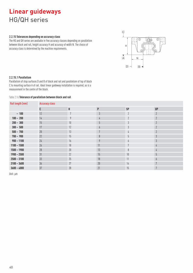
2.2.15 Tolerances depending on accuracy class
The HG and QH series are available in five accuracy classes depending on parallelism
between block and rail, height accuracy H and accuracy of width N. The choice of
accuracy class is determined by the machine requirements.
C
H
A
D B
N
2.2.15.1 Parallelism
Parallelism of stop surfaces D and B of block and rail and parallelism of top of block
C to mounting surface A of rail. Ideal linear guideway installation is required, as is a
measurement in the centre of the block.
Table 2.16 Tolerance of parallelism between block and rail
Rail length [mm]
C H P SP UP
Accuracy class
– 100 12 7 3 2 2
100 – 200 14 9 4 2 2
200 – 300 15 10 5 3 2
300 – 500 17 12 6 3 2
500 – 700 20 13 7 4 2
700 – 900 22 15 8 5 3
900 – 1100 24 16 9 6 3
1100 – 1500 26 18 11 7 4
1500 – 1900 28 20 13 8 4
1900 – 2500 31 22 15 10 5
2500 – 3100 33 25 18 11 6
3100 – 3600 36 27 20 14 7
3600 – 4000 37 28 21 15 7
Unit: µm
Linear guidewaysHG/QH series
40

2.2.15.2 Accuracy – height and width
Height tolerance H
Permissible absolute dimension variance of height H, measured between centre of
screw-on surface C and underside of rail A, with block in any position on the rail.
Height variance of H
Permissible variance of height H between several blocks on a rail, measured in the
same rail position.
Width tolerance N
Permissible absolute dimension variance of width N, measured between centre of
screw-on surfaces D and B, with block in any position on the rail.
Width variance of N
Permissible variance of width N between several blocks on a rail, measured in the
same rail position.
Table 2.17 Height and width tolerances of non-interchangeable types
Series/size Accuracy class Height tolerance of H Width tolerance of N Height variance of H Width variance of N
HG_15, 20
QH_15, 20
Normal (C) ± 0,1 ± 0,1 0,02 0,02
High (H) ± 0,03 ± 0,03 0,01 0,01
Precision (P) 0
– 0
,03
0
– 0
,03
0,006 0,006
Super precision (SP) 0
– 0
,015
0
– 0
,015
0,004 0,004
Ultra precision (UP) 0
– 0
,008
0
– 0
,008
0,003 0,003
HG_25, 30, 35
QH_25, 30, 35
Normal (C) ± 0,1 ± 0,1 0,02 0,03
High (H) ± 0,04 ± 0,04 0,015 0,015
Precision (P) 0
– 0
,04
0
– 0
,04
0,007 0,007
Super precision (SP) 0
– 0
,02
0
– 0
,02
0,005 0,005
Ultra precision (UP) 0
– 0
,01
0
– 0
,01
0,003 0,003
HG_45, 55
QH_45
Normal (C) ± 0,1 ± 0,1 0,03 0,03
High (H) ± 0,05 ± 0,05 0,015 0,02
Precision (P) 0
– 0
,05
0
– 0
,05
0,007 0,01
Super precision (SP) 0
– 0
,03
0
– 0
,03
0,005 0,007
Ultra precision (UP) 0
– 0
,02
0
– 0
,02
0,003 0,005
HG_65 Normal (C) ± 0,1 ± 0,1 0,03 0,03
High (H) ± 0,07 ± 0,07 0,02 0,025
Precision (P) 0
– 0
,07
0
– 0
,07
0,01 0,015
Super precision (SP) 0
– 0
,05
0
– 0
,05
0,007 0,01
Ultra precision (UP) 0
– 0
,03
0
– 0
,03
0,005 0,007
Unit: mm
41

Table 2.18 Height and width tolerances of interchangeable types
Series/size Accuracy class Height tolerance of H Width tolerance of N Height variance of H Width variance of N
HG_15, 20
QH_15, 20
Normal (C) ± 0,1 ± 0,1 0,02 0,02
High (H) ± 0,03 ± 0,03 0,01 0,01
Precision (P) ± 0,015 ± 0,015 0,006 0,006
HG_25, 30, 35
QH_25, 30, 35
Normal (C) ± 0,1 ± 0,1 0,02 0,03
High (H) ± 0,04 ± 0,04 0,015 0,015
Precision (P) ± 0,02 ± 0,02 0,007 0,007
HG_45, 55
QH_45
Normal (C) ± 0,1 ± 0,1 0,03 0,03
High (H) ± 0,05 ± 0,05 0,015 0,02
Precision (P) ± 0,025 ± 0,025 0,007 0,01
HG_65 Normal (C) ± 0,1 ± 0,1 0,03 0,03
High (H) ± 0,07 ± 0,07 0,02 0,025
Precision (P) ± 0,035 ± 0,035 0,01 0,015
Unit: mm
2.2.16 Permissible mounting surface tolerances
Once the requirements relating to the accuracy of the mounting surfaces are met, the
good accuracy, rigidity and lifetime of the HG and QH series linear guideways are
achieved. S1
P
(500)
Parallelism of the reference surface (P)
Table 2.19 Maximum tolerance for parallelism (P)
Series/size
ZO ZA ZB
Preload class
HG/QH_15 25 18 —
HG/QH_20 25 20 18
HG/QH_25 30 22 20
HG/QH_30 40 30 27
HG/QH_35 50 35 30
HG/QH_45 60 40 35
HG_55 70 50 45
HG_65 80 60 55
Unit: μm
Linear guidewaysHG/QH series
42

Table 2.20 Maximum tolerance for height of reference surface (S1)
Series/size
ZO ZA ZB
Preload class
HG/QH_15 130 85 —
HG/QH_20 130 85 50
HG/QH_25 130 85 70
HG/QH_30 170 110 90
HG/QH_35 210 150 120
HG/QH_45 250 170 140
HG_55 300 210 170
HG_65 350 250 200
Unit: μm
2.2.17 Shoulder heights and fillets
Imprecise shoulder heights and fillets of mounting surfaces compromise precision and
may lead to conflicts with the block or rail profiles. The following shoulder heights and
edge profiles must be observed in order to avoid assembly problems.
H1E1
r
r
Block
Rail
E2
r
r
Table 2.21 Shoulder heights and fillets
Series/size Max. edgeradius r
Shoulder height ofreference edge of rail E1
Shoulder height ofreference edge of block E2
Clearanceunder block H1
HG_15 0,5 3,0 4,0 4,3
QH_15 0,5 3,0 4,0 4,0
HG/QH_20 0,5 3,5 5,0 4,6
HG/QH_25 1,0 5,0 5,0 5,5
HG/QH_30 1,0 5,0 5,0 6,0
HG/QH_35 1,0 6,0 6,0 7,5
HG/QH_45 1,0 8,0 8,0 9,5
HG_55 1,5 10,0 10,0 13,0
HG_65 1,5 10,0 10,0 15,0
Unit: mm
43

2.3 Linear guideway, series EG and QE
2.3.1 Properties of the linear guideways, series EG and QE
The HIWIN linear guideways of the EG series with four ball tracks have a low installa-
tion height, making them ideally suited to applications with a low installation space.
Despite this, the EG series has the same properties as the HG series – good loading
capacity, low displacement forces and high efficiency. The ball retainers prevent the
balls from falling out when the block is pulled off the rail during assembly.
The models of the QE series with SynchMotion™ technology offer all the advantages of
the standard series EG. Controlled movement of the balls at a defined distance also
results in improved synchronous performance, higher reliable travel speeds, extended
lubrication intervals and less running noise. Since the installation dimensions of the
QE blocks are identical to those of the EG blocks, they are also fitted on the EGR
standard rail and can therefore be interchanged with ease. For more information, refer
to page 22.
2.3.2 Structure of the EG/QE series
○�4-row recirculation ball bearing guide
○�45° contact angle of ball tracks
○�Ball retainers prevent the balls from falling out when the block is removed
○�Various sealing variants depending on the field of application
○�6 options for connecting grease nipple or lubrication adapter
○�SynchMotion™ technology (QE series)
Fig. Structure of the QE seriesFig. Structure of the EG series
2.3.3 Advantages
○�Zero play
○�Interchangeable
○�High accuracy
○�High loading capacity in all loading directions
○�Low friction losses even with preload thanks to optimized
ball tracks and 2-point contact
Additional advantages of QE series
○�Improved synchronous performance
○�Optimized for higher travel speeds
○�Extendes lubrication intervals
○�Less running noise
2.3.4 Article numbers of the EG/QE series
For EG/QE linear guideways, a distinction is made between interchangeable and non-
interchangeable models. The dimensions of both models are the same. The main differ-
ence is that the block and rail in the interchangeable models can be freely inter-
changed. Block and rail can be ordered separately and fitted by the customer. Their
accuracy extends to class P.
Given their stringent dimensional accuracy check, the interchangeable modules are a
good choice for customers who do not use rails in pairs on one axis. Non-interchange-
able linear guideways are always supplied preassembled. The article numbers of the
series include the dimensions, model, accuracy class, preload etc.
Linear guidewaysEG/QE series
44

2.3.4.1 Non-interchangeable models (custom-assembled)
○�Article number of the fully assembled linear guideway
EG W 25 C C 2 R 1600 ZA H 2 DD E2
Series:EGQE
Block type:W: flange blockH: square block
Size:EG: 15, 20, 25, 30, 35QE: 15, 20, 25, 30, 35
Load type:S: average loadC: heavy load
Block mounting:A: from aboveC: from above or below
Number of blocks per rail
Rail mounting:R: from aboveT: from belowU: from above with large assembly hole(EG/QE15, EG/QE30)
Rail length [mm]
Preload ID: ZO, ZA, ZB
Accuracy class:C, H, P, SP, UP
Rails per axis set 1)
Dust protection 2):None: standard (SS)ZZ, DD, KK
None: standardE2: oil lubrication unit 3)
SE: steel end cap 3)
2.3.4.2 Interchangeable models
○�Article number of EG/QE block
EG W 25 C C Z0 H ZZ E2
Series:EGQE
Block type:W: flange blockH: square block
Size:EG: 15, 20, 25, 30, 35QE: 15, 20, 25, 30, 35
Load type:S: average loadC: heavy load
Block mounting:A: from aboveC: from above or below
Preload ID: ZO, ZA, ZB
Accuracy class: C, H, P
Dust protection 2):None: standard (SS)ZZ, DD, KK
None: standardE2: oil lubrication unit 3)
SE: steel end cap 3)
○�Article number of EG rail
EG R 25 R 1200 H
EG series
Rail
Size: 15, 20, 25, 30, 35Rail mounting:R: from aboveT: from belowU: from above with large assembly hole(EG/QE15, EG/QE30)
Rail length [mm]
Accuracy class: C, H, P
Note:1) The figure 2 is also a quantity, i.e. one item of the above-mentioned article consists of a pair of rails. No number is specified for individual rails.2) You will find an overview of the individual sealing systems on page 20.3) Only available for EG
45

2.3.5 Block types
HIWIN provides square and flange blocks for its linear guideways. Given their low
height and larger mounting surface, flange blocks are better suited to large loads.
Table 2.22 Block types
Type Series/size
Structure Height[mm]
Rail length[mm]
Typical application
Square typeEGH-SA
EGH-CA
24 – 48 100 – 4.000
○�Machining centers
○�NC lathes
○�Grinding machines
○�Precision milling machines
○�High-performance cutting machines
○�Automation technology
○�Transport technology
○�Measuring technology
○�Machines and equipment requiring high
positioning accuracy
Flange typeEGW-SC
EGW-CC
2.3.6 Rail types
In addition to rails with standard fastening from above, HIWIN also provides rails for
fastening from below.
Table 2.23 Rail types
Fastening from above Fastening from below
EGR_R EGR_T
Linear guidewaysEG/QE series
46

2.3.7 Preload
2.3.7.1 Definition
Every rail type can be preloaded. Oversized balls are used for this purpose. Normally a
linear guideway has negative clearance between track and balls to increase rigidity and
precision. The curve shows that the rigidity doubles at higher preload. For rails below
the nominal size of 20, a preload of no more than ZA is recommended to avoid the life-
time being shortened as a result of preload.
P = 0,07 Cdyn 2,8 P
Z0
Elastic deformation
without preload
ZB
Elastic deformation
with high preload
Operating load
Elas
tic d
efor
mat
ion
2.3.7.2 Preload ID
Table 2.24 Preload ID
ID Preload Application Sample applications
Z0 Light preload 0 – 0,02 Cdyn
Constant load direction, low impact, low
accuracy needed
Transport technology, automatic
packaging machines, X-Y axis in industrial
machines, welding machines
ZA Medium preload 0,03 – 0,05 Cdyn High accuracy needed
Machining centres, Z axes for industrial
machines, eroding machines, NC lathes,
precision X-Y tables, measuring
technology
ZB High preload 0,06 – 0,08 Cdyn High rigidity needed, vibration and impact
Machining centres, grinding machines, NC
lathes, horizontal and vertical milling
machines, Z axis of machine tools, high-
performance cutting machines
47

2.3.8 Load ratings and torques
MZ
MYMX
Table 2.25 Load ratings and torques for series EG/QE
Series/size Dynamic loadrating Cdyn [N]*
Static loadrating C0 [N]
MX MY MZ
Dynamic moment [Nm]
MOX MOY MOZ
Static moment [Nm]
EG_15S 5350 9400 45 22 22 80 40 40
QE_15S 8560 8790 68 29 29 70 30 30
EG_15C 7830 16190 62 48 48 130 100 100
QE_15C 12530 15280 98 73 73 120 90 90
EG_20S 7230 12740 73 34 34 130 60 60
QE_20S 11570 12180 123 47 47 130 50 50
EG_20C 10310 21130 107 78 78 220 160 160
QE_20C 16500 20210 171 122 122 210 150 150
EG_25S 11400 19500 134 70 70 230 120 120
QE_25S 18240 18900 212 96 96 220 100 100
EG_25C 16270 32400 190 160 160 380 320 320
QE_25C 26030 31490 305 239 239 370 290 290
EG_30S 16420 28100 233 122 122 400 210 210
QE_30S 26270 27820 377 169 169 400 180 180
EG_30C 23700 47460 339 274 274 680 550 550
QE_30C 37920 46630 544 414 414 670 510 510
EG_35S 22660 37380 339 187 187 560 310 310
QE_35S 36390 36430 609 330 330 610 330 330
EG_35C 33350 64840 504 354 354 980 690 690
QE_35C 51180 59280 863 648 648 1000 750 750
* Dynamic load rating for travel distance of 50 000 m
Linear guidewaysEG/QE series
48

2.3.9 Rigidity
Rigidity depends on preload. The adjacent formula can be used to determine
deformation depending on rigidity.
: Deformation [μm]
P: Operating load [N]
k: Rigidity [N/μm]
Table 2.26 Radial rigidity for series EG/QE
Load class Series/size
ZO ZA ZB
Rigidity depending on preload
Average load EG_15S 105 126 141
QE_15S 96 115 128
EG_20S 126 151 168
QE_20S 116 139 153
EG_25S 156 187 209
QE_25S 137 165 184
EG_30S 184 221 246
QE_30S 169 203 226
EG_35S 221 265 295
QE_35S 214 257 287
Heavy load EG_15C 172 206 230
QE_15C 157 187 209
EG_20C 199 238 266
QE_20C 183 219 245
EG_25C 246 296 329
QE_25C 219 263 293
EG_30C 295 354 395
QE_30C 271 326 363
EG_35C 354 425 474
QE_35C 333 399 445
Unit: N⁄μm
49

2.3.10 Dimensions of the EG/QE blocks
2.3.10.1 EGH/QEH
WRN
H1
H
WBB1
T H2
G
EGH/QEH-CA
L1K2
L
4–M × lC
H3
K1
EGH/QEH-SAE
GLL1
2–M × l
K1
K2
Table 2.27 Dimensions of the block
Series/size
H H1 N
Installationdimensions [mm]
W B B1 C L1 L K1 K2 G M × l T H2 H3
Dimensions of the block [mm]
Cdyn C0
Load ratings [N] Weight[kg]
EGH15SA24 4,5 9,5 34 26,0 4,0
— 23,1 40,1 14,803,50 5,7 M4 × 6 6,0 5,50 6,0
5350 9400 0,09
EGH15CA 26 39,8 56,8 10,15 7830 16190 0,15
QEH15SA24 4,0 9,5 34 26,0 4,0
— 23,1 40,1 14,803,50 5,7 M4 × 6 6,0 5,50 6,0
8560 8790 0,09
QEH15CA 26 39,8 56,8 10,15 12530 15280 0,15
EGH20SA28 6,0 11,0 42 32,0 5,0
— 29,0 50,0 18,754,15 12,0 M5 × 7 7,5 6,00 6,0
7230 12740 0,15
EGH20CA 32 48,1 69,1 12,30 10310 21130 0,24
QEH20SA28 6,0 11,0 42 32,0 5,0
— 29,0 50,0 18,754,15 12,0 M5 × 7 7,5 6,00 6,5
11570 12180 0,15
QEH20CA 32 48,1 69,1 12,30 16500 20210 0,23
EGH25SA33 7,0 12,5 48 35,0 6,5
— 35,5 59,1 21,904,55 12,0 M6 × 9 8,0 8,00 8,0
11400 19500 0,25
EGH25CA 35 59,0 82,6 16,15 16270 32400 0,41
QEH25SA33 6,2 12,5 48 35,0 6,5
— 35,5 60,1 21,905,00 12,0 M6 × 9 8,0 8,00 8,0
18240 18900 0,24
QEH25CA 35 59,0 83,6 16,15 26030 31490 0,40
EGH30SA42 10,0 16,0 60 40,0 10,0
— 41,5 69,5 26,756,00 12,0 M8 × 12 9,0 8,00 9,0
16420 28100 0,45
EGH30CA 40 70,1 98,1 21,05 23700 47460 0,76
QEH30SA42 10,0 16,0 60 40,0 10,0
— 41,5 67,5 25,756,00 12,0 M8 × 12 9,0 8,00 9,0
26270 27820 0,44
QEH30CA 40 70,1 96,1 20,05 37920 46630 0,75
EGH35SA48 11,0 18,0 70 50,0 10,0
— 45,0 75,0 28,507,00 12,0 M8 × 12 10,0 8,50 8,5
22660 37380 0,74
EGH35CA 50 78,0 108,0 20,00 33350 64840 1,10
QEH35SA48 11,0 18,0 70 50,0 10,0
— 51,0 76,0 30,306,25 12,0 M8 × 12 10,0 8,50 8,5
36390 36430 0,58
QEH35CA 50 83,0 108,0 21,30 51180 59280 0,90
For dimensions of rail, see page 52, for standard and optional lubrication adapter, see page 117.
Linear guidewaysEG/QE series
50

2.3.10.2 EGW/QEW
H1
WRN
T 1H
WBB1
T H2
G
EGW/QEW-CC
C
LL1
4–M
H3
K1
EGW/QEW-SCE
GLL1
2–M
K1
K2 K2
Table 2.28 Dimensions of the block
Series/size
H H1 N
Installationdimensions [mm]
W B B1 C L1 L K1 K2 G M T T1 H2 H3
Dimensions of the block [mm]
Cdyn C0
Load Ratings[N]
Weight[kg]
EGW15SC24 4,5 18,5 52 41,0 5,5
— 23,1 40,1 14,803,50 5,7 M5 5,0 7,0 5,50 6,0
5350 9400 0,12
EGW15CC 26 39,8 56,8 10,15 7830 16190 0,21
QEW15SC24 4,0 18,5 52 41,0 5,5
— 23,1 40,1 14,803,50 5,7 M5 5,0 0,0 5,50 6,0
8560 8790 0,12
QEW15CC 26 39,8 56,8 10,15 12530 15280 0,21
EGW20SC28 6,0 19,5 59 49,0 5,0
— 29,0 50,0 18,754,15 12,0 M6 7,0 9,0 6,00 6,0
7230 12740 0,19
EGW20CC 32 48,1 69,1 12,30 10310 21130 0,32
QEW20SC28 6,0 19,5 59 49,0 5,0
— 29,0 50,0 18,754,15 12,0 M6 7,0 0,0 6,00 6,5
11570 12180 0,19
QEW20CC 32 48,1 69,1 12,30 16500 20210 0,31
EGW25SC33 7,0 25,0 73 60,0 6,5
— 35,5 59,1 21,904,55 12,0 M8 7,5 10,0 8,00 8,0
11400 19500 0,35
EGW25CC 35 59,0 82,6 16,15 16270 32400 0,59
QEW25SC33 6,2 25,0 73 60,0 6,5
— 35,5 60,1 21,905,00 12,0 M8 7,5 0,0 8,00 8,0
18240 18900 0,34
QEW25CC 35 59,0 83,6 16,15 26030 31490 0,58
EGW30SC42 10,0 31,0 90 72,0 9,0
— 41,5 69,5 26,756,00 12,0 M10 7,0 10,0 8,00 9,0
16420 28100 0,62
EGW30CC 40 70,1 98,1 21,05 23700 47460 1,04
QEW30SC42 10,0 31,0 90 72,0 9,0
— 41,5 67,5 25,756,00 12,0 M10 7,0 0,0 8,00 9,0
26270 27820 0,61
QEW30CC 40 70,1 96,1 20,05 37920 46630 1,03
EGW35SC48 11,0 33,0 100 82,0 9,0
— 45,0 75,0 28,507,00 12,0 M10 10,0 13,0 8,50 8,5
22660 37380 0,91
EGW35CC 50 78,0 108,0 20,00 33350 64840 1,40
QEW35SC48 11,0 33,0 100 82,0 9,0
— 51,0 76,0 30,306,25 12,0 M10 10,0 13,0 8,50 8,5
36390 36430 0,77
QEW35CC 50 83,0 108,0 21,30 51180 59280 1,19
For dimensions of rail, see page 52, for standard and optional lubrication adapter, see page 117.
51
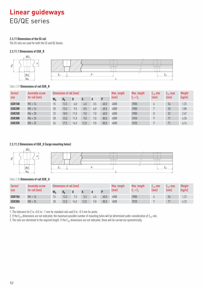
2.3.11 Dimensions of the EG rail
The EG rails are used for both the EG and QE blocks.
2.3.11.1 Dimensions of EGR_R
ØD
ØdLWR
h
E1 P E2
HR
Table 2.29 Dimensions of rail EGR_R
Series/size
Assembly screwfor rail [mm]
WR HR D h d P
Dimensions of rail [mm] Max. length[mm]
Max. lengthE1 = E2
E1/2 min[mm]
E1/2 max[mm]
Weight[kg/m]
EGR15R M3 × 16 15 12,5 6,0 4,5 3,5 60,0 4000 3900 6 54 1,25
EGR20R M5 × 16 20 15,5 9,5 8,5 6,0 60,0 4000 3900 7 53 2,08
EGR25R M6 × 20 23 18,0 11,0 9,0 7,0 60,0 4000 3900 8 52 2,67
EGR30R M6 × 25 28 23,0 11,0 9,0 7,0 80,0 4000 3920 9 71 4,35
EGR35R M8 × 25 34 27,5 14,0 12,0 9,0 80,0 4000 3920 9 71 6,14
2.3.11.2 Dimensions of EGR_U (large mounting holes)
ØD
ØdLWR
h
E1 P E2
HR
Table 2.30 Dimensions of rail EGR_U
Series/size
Assembly screwfor rail [mm]
WR HR D h d P
Dimensions of rail [mm] Max. length[mm]
Max. lengthE1 = E2
E1/2 min[mm]
E1/2 max[mm]
Weight[kg/m]
EGR15U M4 × 16 15 12,5 7,5 5,3 4,5 60,0 4000 3900 6 54 1,23
EGR30U M8 × 25 28 23,0 14,0 12,0 9,0 80,0 4000 3920 9 71 4,23
Note:
1. The tolerance for E is +0.5 to –1 mm for standard rails and 0 to –0.3 mm for joints.
2. If the E1/2 dimensions are not indicated, the maximum possible number of mounting holes will be determined under consideration of E1/2 min.
3. The rails are shortened to the required length. If the E1/2 dimensions are not indicated, these will be carried out symmetrically.
Linear guidewaysEG/QE series
52

2.3.11.3 Dimensions of EGR_T (rail mounting from below)
LWR S
HR
h
E1 P E2
Table 2.31 Dimensions of rail EGR_T
Series/size
WR HR S h P
Dimensions of rail [mm] Max. length[mm]
Max. lengthE1 = E2
E1/2 min[mm]
E1/2 max[mm]
Weight[kg/m]
EGR15T 15 12,5 M5 7,0 60,0 4000 3900 6 54 1,26
EGR20T 20 15,5 M6 9,0 60,0 4000 3900 7 53 2,15
EGR25T 23 18,0 M6 10,0 60,0 4000 3900 8 52 2,79
EGR30T 28 23,0 M8 14,0 80,0 4000 3920 9 71 4,42
EGR35T 34 27,5 M8 17,0 80,0 4000 3920 9 71 6,34
Note:
1. The tolerance for E is +0.5 to –1 mm for standard rails and 0 to –0.3 mm for joints.
2. If the E1/2 dimensions are not indicated, the maximum possible number of mounting holes will be determined under consideration of E1/2 min.
3. The rails are shortened to the required length. If the E1/2 dimensions are not indicated, these will be carried out symmetrically.
2.3.11.4 Calculating the length of rails
HIWIN offers rails in customised lengths. To prevent the risk of the end of the rail
becoming unstable, the value E must not exceed half of the distance between the
mounting holes (P). At the same time, the value E1/2 should be between E1/2 min and
E1/2 max so that the mounting hole does not rupture.
L: Total length of the rail [mm]
n: Number of mounting holes
P: Distance between two mounting holes [mm]
E1/2: Distance from the middle of the last
mounting hole to the end of the rail [mm]
PL
E2E1
n = Number of mounting holes
2.3.11.5 Tightening torques for mounting bolts
Insufficient tightening of the mounting bolts strongly compromises the precision of the
linear guideway; the following tightening torques are therefore recommended for the
relevant screw sizes.
Table 2.32 Tightening torques of the mounting bolts according to ISO 4762-12.9
EG_15 M3 × 16 2
EG_15U M4 × 16 4
EG_20 M5 × 16 9
EG_25 M6 × 20 13
Series/size Screw size Torque [Nm] Series/size Screw size Torque [Nm]EG_30 M6 × 25 13
EG_30U M8 × 25 30
EG_35 M8 × 25 30
53
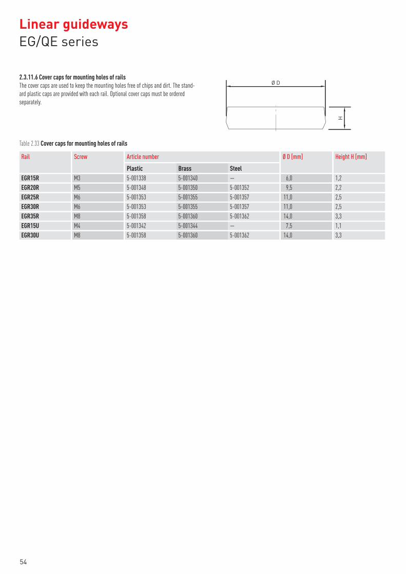
2.3.11.6 Cover caps for mounting holes of rails
The cover caps are used to keep the mounting holes free of chips and dirt. The stand-
ard plastic caps are provided with each rail. Optional cover caps must be ordered
separately.
Ø D
H
Table 2.33 Cover caps for mounting holes of rails
Rail Screw
Plastic Brass Steel
Article number Ø D [mm] Height H [mm]
EGR15R M3 5-001338 5-001340 — 6,0 1,2
EGR20R M5 5-001348 5-001350 5-001352 9,5 2,2
EGR25R M6 5-001353 5-001355 5-001357 11,0 2,5
EGR30R M6 5-001353 5-001355 5-001357 11,0 2,5
EGR35R M8 5-001358 5-001360 5-001362 14,0 3,3
EGR15U M4 5-001342 5-001344 — 7,5 1,1
EGR30U M8 5-001358 5-001360 5-001362 14,0 3,3
Linear guidewaysEG/QE series
54

2.3.12 Sealing systems
Various sealing systems are available for HIWIN blocks. You will find an overview
on page 20. The table below shows the total length of the blocks with the different
sealing systems. Sealing systems suitable for these sizes are available.
Table 2.34 Total length of blocks with different sealing systems
Series/size SS DD ZZ KK SW ZWX
Total length L
EG_15S 40,1 44,1 41,7 45,7 — —
QE_15S 40,1 44,1 42,1 46,1 — —
EG_15C 56,8 60,8 58,4 62,4 — —
QE_15C 56,8 60,8 58,8 62,8 — —
EG_20S 50,0 54,0 51,6 55,6 — —
QE_20S 50,0 54,0 52,0 56,0 — —
EG_20C 69,1 73,1 70,7 74,7 — —
QE_20C 69,1 73,1 71,1 75,1 — —
EG_25S 59,1 63,1 61,1 65,1 — —
QE_25S 60,1 65,1 62,1 67,1 — —
EG_25C 82,6 86,6 84,6 88,6 — —
QE_25C 83,6 88,6 85,6 90,6 — —
EG_30S 69,5 73,5 71,5 75,5 — —
QE_30S 67,5 72,5 69,5 74,5 — —
EG_30C 98,1 102,1 100,1 104,1 — —
QE_30C 96,1 101,1 98,1 103,1 — —
EG_35S 75,0 79,0 78,0 82,0 — —
QE_35S 76,0 80,0 79,0 83,0 — —
EG_35C 108,0 112,0 111,0 115,0 — —
QE_35C 108,0 112,0 111,0 115,0 — —
Unit: mm
2.3.12.1 Designation of sealing sets
The sealing sets are always supplied along with the assembly material and include the
parts needed in addition to the standard seal.
EG 15 SS
Series:EGQE
Size:EG: 15, 20, 25, 30, 35QE: 15, 20, 25, 30, 35
Dust protection ID:SS: standard sealZZ: end seal with scraperDD: double end sealKK: double end seal with scraper
55

2.3.13 Friction
The table shows the maximum frictional resistance of the individual end seal. Depend-
ing on sealing setup (SS, ZZ, DD, KK), the value may have to be multiplied. The values
indicated apply to blocks on uncoated rails. Higher friction forces occur on coated
rails.
Table 2.35 Frictional resistance of single-lipped seals
EG_15 1,0
EG_20 1,0
EG_25 1,0
EG_30 1,5
EG_35 2,0
Series/size Friction force [N] Series/size Friction force [N]QE_15 1,1
QE_20 1,4
QE_25 1,7
QE_30 2,1
QE_35 2,3
2.3.14 Lubrication unit E2
You will find more information about the lubrication unit in the general information in
the lubrication unit E2 chapter (page 13).
T
LV
H
W
Table 2.36 Dimensions of block with lubrication unit E2
ModelW H T V LSS
1) LZZ 1) LDD
1) LKK 1)
Dimensions of the block [mm] Oil quantity[cm3]
Mileage 2)
[km]
EG_15S 33,3 18,7 11,5 3,0 54,6 56,2 58,6 60,2 1,7 2000
EG_15C 33,3 18,7 11,5 3,0 71,3 72,9 75,3 76,9 1,7 2000
EG_20S 41,3 20,9 13,0 3,0 66,0 67,6 70,0 71,6 2,9 3000
EG_20C 41,3 20,9 13,0 3,0 85,1 86,7 89,1 90,7 2,9 3000
EG_25S 47,3 24,9 13,0 3,0 75,1 77,1 79,1 81,1 4,8 5000
EG_25C 47,3 24,9 13,0 3,0 98,6 100,6 102,6 104,6 4,8 5000
EG_30S 59,3 31,0 13,0 3,0 85,5 87,5 89,5 91,5 8,9 9000
EG_30C 59,3 31,0 13,0 3,0 114,1 116,1 118,1 120,1 8,9 9000
1) Total length depending on selected dust protection. SS = Standard dust protection2) Mileage at which the oil tank level should be checked at the very latest
Linear guidewaysEG/QE series
56

2.3.15 Tolerances depending on accuracy class
The EG and QE series are available in five accuracy classes depending on parallelism
between block and rail, height accuracy H and accuracy of width N. The choice of
accuracy class is determined by the machine requirements.
NA
H
BD
C
2.3.15.1 Parallelism
Parallelism of stop surfaces D and B of block and rail and parallelism of top of block
C to mounting surface A of rail. Ideal linear guideway installation is required, as is a
measurement in the centre of the block.
Table 2.37 Tolerance of parallelism between block and rail
Rail length [mm]
C H P SP UP
Accuracy class
– 100 12 7 3 2 2
100 – 200 14 9 4 2 2
200 – 300 15 10 5 3 2
300 – 500 17 12 6 3 2
500 – 700 20 13 7 4 2
700 – 900 22 15 8 5 3
900 – 1100 24 16 9 6 3
1100 – 1500 26 18 11 7 4
1500 – 1900 28 20 13 8 4
1900 – 2500 31 22 15 10 5
2500 – 3100 33 25 18 11 6
3100 – 3600 36 27 20 14 7
3600 – 4000 37 28 21 15 7
Unit: µm
57

2.3.15.2 Accuracy – height and width
Height tolerance H
Permissible absolute dimension variance of height H, measured between centre of
screw-on surface C and underside of rail A, with block in any position on the rail.
Height variance of H
Permissible variance of height H between several blocks on a rail, measured in the
same rail position.
Width tolerance N
Permissible absolute dimension variance of width N, measured between centre of
screw-on surfaces D and B, with block in any position on the rail.
Width variance of N
Permissible variance of width N between several blocks on a rail, measured in the
same rail position.
Table 2.38 Height and width tolerances of non-interchangeable types
Series/size Accuracy class Height tolerance of H Width tolerance of N Height variance of H Width variance of N
EG_15, 20
QE_15, 20
Normal (C) ± 0,1 ± 0,1 0,02 0,02
High (H) ± 0,03 ± 0,03 0,01 0,01
Precision (P) 0
– 0
,03
0
– 0
,03
0,006 0,006
Super precision (SP) 0
– 0
,015
0
– 0
,015
0,004 0,004
Ultra precision (UP) 0
– 0
,008
0
– 0
,008
0,003 0,003
EG_25, 30, 35
QE_25, 30, 35
Normal (C) ± 0,1 ± 0,1 0,02 0,03
High (H) ± 0,04 ± 0,04 0,015 0,015
Precision (P) 0
– 0
,04
0
– 0
,04
0,007 0,007
Super precision (SP) 0
– 0
,02
0
– 0
,02
0,005 0,005
Ultra precision (UP) 0
– 0
,01
0
– 0
,01
0,003 0,003
Unit: mm
Table 2.39 Height and width tolerances of interchangeable types
Series/size Accuracy class Height tolerance of H Width tolerance of N Height variance of H Width variance of N
EG_15, 20
QE_15, 20
Normal (C) ± 0,1 ± 0,1 0,02 0,02
High (H) ± 0,03 ± 0,03 0,01 0,01
Precision (P) ± 0,015 ± 0,015 0,006 0,006
EG_25, 30, 35
QE_25, 30, 35
Normal (C) ± 0,1 ± 0,1 0,02 0,03
High (H) ± 0,04 ± 0,04 0,015 0,015
Precision (P) ± 0,02 ± 0,02 0,007 0,007
Unit: mm
Linear guidewaysEG/QE series
58

2.3.16 Permissible mounting surface tolerances
Once the requirements relating to the accuracy of the mounting surfaces are met, the
good accuracy, rigidity and lifetime of the EG and QE series linear guideways are
achieved.
S1
(500)P
Parallelism of the reference surface (P)
Table 2.40 Maximum tolerance for parallelism (P)
Series/size
ZO ZA ZB
Preload class
EG/QE_15 25 18 —
EG/QE_20 25 20 18
EG/QE_25 30 22 20
EG/QE_30 40 30 27
EG/QE_35 50 35 30
Unit: μm
Table 2.41 Maximum height tolerance of reference surface (S1)
Series/size
ZO ZA ZB
Preload class
EG/QE_15 130 85 —
EG/QE_20 130 85 50
EG/QE_25 130 85 70
EG/QE_30 170 110 90
EG/QE_35 210 150 120
Unit: μm
2.3.17 Shoulder heights and fillets
Imprecise shoulder heights and fillets of mounting surfaces compromise precision and
may lead to conflicts with the block or rail profiles. The following shoulder heights and
edge profiles must be observed in order to avoid assembly problems.H1 E1
r1
r2
r2
Block
Rail
E2
Table 2.42 Shoulder heights and fillets
Series/size Max. edgeradius r1
Max. edgeradius r2
Shoulder height ofreference edge of rail E1
Shoulder height ofreference edge of block E2
Clearanceunder block H1
EG/QE_15 0,5 0,5 2,7 5,0 4,5
EG/QE_20 0,5 0,5 5,0 7,0 6,0
EG/QE_25 1,0 1,0 5,0 7,5 7,0
EG/QE_30 1,0 1,0 7,0 7,0 10,0
EG_35 1,0 1,0 7,5 9,5 11,0
QE_35 1,0 1,5 7,5 9,5 11,0
Unit: mm
59

2.4 Linear guideway, series WE
2.4.1 Properties of the linear guideway, series WE
The HIWIN linear guideways of the WE series are based on proven HIWIN technology.
Their large rail width and low installation height permit a compact design and high
torque loading capacity.
2.4.2 Structure of the WE series
○�4-row recirculation ball bearing guide
○�45° contact angle
○�Ball retainers prevent the balls from falling out when the block is removed
○�Low installation height
○�Wide linear guideway for high torque loading capacity
○�Large mounting surface on block
Fig. Structure of the WE series
2.4.3 Advantages
○�Compact and low-cost design thanks to high torque loading capacity
○�High efficiency thanks to low friction losses
2-row mounting holes
50 % wider than standard series
○�The block’s large mounting surface supports the transfer of higher torques
○�The 45° arrangement of ball tracks permits high loading from all directions
○�Optimized geometry and high loading capacity thanks to FEM analysis of rail and
block
Linear guidewaysWE series
60

2.4.4 Article numbers of the WE series
For WE linear guideways, a distinction is made between interchangeable and non-
interchangeable models. The dimensions of both models are the same. The main
difference is that the block and rail in the interchangeable models can be freely
interchanged. Block and rail can therefore be ordered separately and fitted by the
customer.
Their accuracy extends to class P. Given their stringent dimensional accuracy check,
the interchangeable modules are a good choice for customers who do not use rails in
pairs on one axis. Non-interchangeable linear guideways are always supplied pre-
assembled. The article numbers of the series include the dimensions, model, accuracy
class, preload etc.
2.4.4.1 Non-interchangeable models (custom-assembled)
○�Item number of the fully assembled linear guideway
WE W 27 C C 2 R 1600 ZA H 2 KK
WE series
Block type:W: flange blockH: square block
Size: 17, 21, 27, 35, 50
Load type:C: heavy load
Block mounting:A: from aboveC: from above or below
Number of blocks per rail
Rail mounting:R: from above
Rail length [mm]
Preload ID: ZO, ZA, ZB
Accuracy class:C, H, P, SP, UP
Rails per axis set 1)
Dust protection 2):None: standard (SS)ZZ, DD, KK
2.4.4.2 Interchangeable models
○�Article number of WE block
WE W 27 C C ZA H ZZ
WE series
Block type:W: flange blockH: square block
Size: 17, 21, 27, 35, 50
Load type:C: heavy load
Block mounting:A: from aboveC: from above or below
Preload ID: ZO, ZA, ZB
Accuracy class: C, H, P
Dust protection 2):None: standard (SS)ZZ, DD, KK
○�Article number of WE rail
WE R 27 R 1200 H
WE series
Rail
Size: 17, 21, 27, 35, 50Rail mounting:R: from above
Rail length [mm]
Accuracy class: C, H, P
Note1) The figure 2 is also a quantity, i.e. one item of the above-mentioned article consists of a pair of rails. No number is specified for individual rails.2) You will find an overview of the individual sealing systems on page 20.
61

2.4.5 Block types
HIWIN provides square and flange blocks for its linear guideways. Given their low
height and larger mounting surface, flange blocks are better suited for large loads.
Table 2.43 Block types
Type SeriesSize
Structure Height[mm]
Rail length[mm]
Typical application
Square type WEH-CA
17 – 50 100 – 4.000
○�Automation
○�Handling industry
○�Measuring and test technology
○�Semiconductor industry
○�Injection moulding machines
○�Linear axesFlange type WEW-CC
2.4.6 Preload
2.4.6.1 Definition
Every rail type can be preloaded. Oversized balls are used for this purpose. Normally a
linear guideway has negative clearance between track and balls to increase rigidity and
precision. The curve shows that the rigidity doubles at higher preload.
P = 0,07 Cdyn 2,8 P
Z0
Elastic deformation
without preload
ZB
Elastic deformation
with high preload
Operating load
Elas
tic d
efor
mat
ion
2.4.6.2 Preload ID
Table 2.44 Preload ID
ID Preload ApplicationZO Light preload 0 – 0,02 Cdyn Constant load direction, low impact, low accuracy needed
ZA Medium preload 0,03 – 0,05 Cdyn High accuracy needed
ZB High preload 0,06 – 0,08 Cdyn High rigidity needed, vibration and impact
Linear guidewaysWE series
62

2.4.7 Load ratings and torques
MX MY
MZ
Table 2.45 Load ratings and torques for series WE
Series/size Dynamic loadrating Cdyn [N]*
Static loadrating C0 [N]
MX MY MZ
Dynamic moment [Nm]
MOX MOY MOZ
Static moment [Nm]
WE_17C 5230 9640 82 34 34 150 62 62
WE_21C 7210 13700 122 53 53 230 100 100
WE_27C 12400 21600 242 98 98 420 170 170
WE_35C 29800 49400 893 405 405 1480 670 670
WE_50C 61520 97000 2556 1244 1244 4030 1960 1960
* Dynamic load rating for travel distance of 50 000 m
2.4.8 Rigidity
Rigidity depends on preload. The adjacent formula can be used to determine
deformation depending on rigidity.
: Deformation [μm]
P: Operating load [N]
k: Rigidity [N/μm]
Table 2.46 Radial rigidity for series WE
Load class Series/size
ZO ZA ZB
Rigidity depending on preload
Heavy load WE_17C 128 166 189
WE_21C 154 199 228
WE_27C 187 242 276
WE_35C 281 364 416
WE_50C 428 554 633
Unit: N⁄μm
63

2.4.9 Dimensions of the WE blocks
2.4.9.1 WEH
WR
WB
K2 L1
K1
H3
B1
H2
H1
HT
N
WG L
CB
6–M×l
K1
4–M×l
WE_17WE_21
WE_27WE_35WE_50
Table 2.47 Dimensions of the block
Series/size
H H1 N
Installationdimensions [mm]
W B B1 C L1 L K1 K2 G M × l T H2 H3
Dimensions of the block [mm]
Cdyn C0
Load ratings [N] Weight[kg]
WEH17CA 17 2,5 8,5 50 29,0 10,5 15 35,0 50,6 — 3,10 4,9 M4 × 5 6,0 4,00 3,0 5230 9640 0,12
WEH21CA 21 3,0 8,5 54 31,0 11,5 19 41,7 59,0 14,68 3,65 12,0 M5 × 6 8,0 4,50 4,2 7210 13700 0,20
WEH27CA 27 4,0 10,0 62 46,0 8,0 32 51,8 72,8 14,15 3,50 12,0 M6 × 6 10,0 6,00 5,0 12400 21600 0,35
WEH35CA 35 4,0 15,5 100 76,0 12,0 50 77,6 102,6 18,35 5,25 12,0 M8 × 8 13,0 8,00 6,5 29800 49400 1,10
WEH50CA 50 7,5 20,0 130 100,0 15,0 65 112,0 140,0 28,05 6,00 12,9 M10 × 15 19,5 12,00 10,5 61520 97000 3,16
For dimensions of rail, see page 66, for standard and optional lubrication adapter, see page 117.
Linear guidewaysWE series
64

2.4.9.2 WEW
WR
WB
K2 L1
K1
H3
B1
H2
H1
T 1H
T
N
WG L
CB
6–M
Table 2.48 Dimensions of the block
Series/size
H H1 N
Installationdimensions [mm]
W B B1 C L1 L K1 K2 G M T T1 H2 H3
Dimensions of the block [mm]
Cdyn C0
Load Ratings[N]
Weight[kg]
WEW17CC 17 2,5 13,5 60 53,0 3,5 26 35,0 50,6 — 3,10 4,9 M4 5,3 6,0 4,00 3,0 5230 9640 0,13
WEW21CC 21 3,0 15,5 68 60,0 4,0 29 41,7 59,0 9,68 3,65 12,0 M5 7,3 8,0 4,50 4,2 7210 13700 0,23
WEW27CC 27 4,0 19,0 80 70,0 5,0 40 51,8 72,8 10,15 3,50 12,0 M6 8,0 10,0 6,00 5,0 12400 21600 0,43
WEW35CC 35 4,0 25,5 120 107,0 6,5 60 77,6 102,6 13,35 5,25 12,0 M8 11,2 14,0 8,00 6,5 29800 49400 1,26
WEW50CC 50 7,5 36,0 162 144,0 9,0 80 112,0 140,0 20,55 6,00 12,9 M10 14,0 18,0 12,00 10,5 61520 97000 3,71
For dimensions of rail, see page 66, for standard and optional lubrication adapter, see page 117.
65

2.4.10 Dimensions of the WE rail
2.4.10.1 Dimensions of WER_R
L
h
P
WB
WR
HR
E
N
E
d
D
Table 2.49 Dimensions of rail WER_R
Series/size
Assembly screwfor rail [mm]
WR WB HR D h d P
Dimensions of the rail [mm] Max. length[mm]
E1/2 min[mm]
E1/2 max[mm]
Weight[kg/m]
WER17R M4 × 12 33 18 9,3 7,5 5,3 4,5 40,0 4000 6 34 2,20
WER21R M4 × 12 37 22 11,0 7,5 5,3 4,5 50,0 4000 6 44 3,00
WER27R M4 × 16 42 24 15,0 7,5 5,3 4,5 60,0 4000 6 54 4,70
WER35R M6 × 20 69 40 19,0 11,0 9,0 7,0 80,0 4000 8 72 9,70
WER50R M8 × 25 90 60 24,0 14,0 12,0 9,0 80,0 4000 9 71 14,60
Note
1. The tolerance for E is +0.5 to –1 mm for standard rails and 0 to –0.3 mm for joints.
2. If the E1/2 dimensions are not indicated, the maximum possible number of mounting holes will be determined under consideration of E1/2 min.
3. The rails are shortened to the required length. If the E1/2 dimensions are not indicated, these will be carried out symmetrically.
2.4.10.2 Calculating the length of rails
HIWIN offers rails in customized lengths. To prevent the risk of the end of the rail
becoming unstable, the value E must not exceed half of the distance between the
mounting holes (P). At the same time, the value E1/2 should be between E1/2 min and
E1/2 max so that the mounting hole does not rupture.
L: Total length of the rail [mm]
n: Number of mounting holes
P: Distance between two mounting holes [mm]
E: Distance from the middle of the last mounting
hole to the end of the rail [mm]
L = (n-1)×P+2×E
n = Number of mounting holes
LE P E
Linear guidewaysWE series
66

2.4.10.3 Tightening torques for mounting bolts
Insufficient tightening of the mounting bolts compromises the function and precision
of the linear guideways. The following tightening torques are recommended for the
screw sizes.
Table 2.50 Tightening torques of the mounting bolts according to ISO 4762-12.9
WE_17 M4 4
WE_21 M4 4
WE_27 M4 4
Series/size Screw size Torque [Nm] Series/size Screw size Torque [Nm]WE_35 M6 13
WE_50 M8 30
2.4.10.4 Cover caps for mounting holes of rails
The cover caps are used to keep the mounting holes free of chips and dirt. The stand-
ard plastic caps are provided with each rail. Optional cover caps must be ordered
separately.
Ø D
H
Table 2.51 Cover caps for mounting holes of rails
Rail Screw
Plastic Brass Steel
Article number Ø D [mm] Height H [mm]
WER17R M4 5-001342 5-001344 — 7,5 1,1
WER21R M4 5-001342 5-001344 — 7,5 1,1
WER27R M4 5-001342 5-001344 — 7,5 1,1
WER35R M6 5-001353 5-001355 5-001357 11,0 2,5
WER50R M8 5-001358 5-001360 5-001362 14,0 3,3
67

2.4.11 Sealing systems
Various sealing systems are available for HIWIN blocks. You will find an overview
on page 20. The table below shows the total length of the blocks with the different
sealing systems. Sealing systems suitable for these sizes are available.
Table 2.52 Total length of block with different sealing systems
Series/size SS DD ZZ KK SW ZWX
Total length L
WE_17C 50,6 53,8 52,6 55,8 — —
WE_21C 59,0 63,0 61,0 65,0 — —
WE_27C 72,8 76,8 74,8 78,8 — —
WE_35C 102,6 106,6 105,6 109,6 — —
WE_50C 140,0 145,0 142,0 147,0 — —
Unit: mm
2.4.11.1 Designation of sealing sets
The sealing sets are always supplied along with the assembly material and include the
parts needed in addition to the standard seal.
WE 21 SS
WE series
Size: 17, 21, 27, 35, 50
Dust protection ID:SS: standard sealZZ: end seal with scraperDD: double end sealKK: double end seals with scrape
2.4.12 Friction
The table shows the maximum frictional resistance of the individual end seal. Depend-
ing on sealing setup (SS, ZZ, DD, KK), the value may have to be multiplied. The values
indicated apply to blocks on uncoated rails. Higher friction forces occur on coated
rails.
Table 2.53 Frictional resistance of single-lipped seals
WE_17 1,2
WE_21 2,0
WE_27 2,9
Series/size Friction force [N] Series/size Friction force [N]WE_35 3,9
WE_50 3,9
Linear guidewaysWE series
68

2.4.13 Tolerances depending on accuracy class
The WE series are available in five accuracy classes depending on parallelism between
block and rail, height accuracy H and accuracy of width N. The choice of accuracy class
is determined by the machine requirements.
H
AN
C
D B
2.4.13.1 Parallelism
Parallelism of stop surfaces D and B of block and rail and parallelism of top of block
C to mounting surface A of rail. Ideal linear guideway installation is required, as is a
measurement in the centre of the block.
Table 2.54 Tolerance of parallelism between block and rail
Rail length [mm]
C H P SP UP
Accuracy class
– 100 12 7 3 2 2
100 – 200 14 9 4 2 2
200 – 300 15 10 5 3 2
300 – 500 17 12 6 3 2
500 – 700 20 13 7 4 2
700 – 900 22 15 8 5 3
900 – 1100 24 16 9 6 3
1100 – 1500 26 18 11 7 4
1500 – 1900 28 20 13 8 4
1900 – 2500 31 22 15 10 5
2500 – 3100 33 25 18 11 6
3100 – 3600 36 27 20 14 7
3600 – 4000 37 28 21 15 7
Unit: µm
69

2.4.13.2 Accuracy – height and width
Height tolerance H
Permissible absolute dimension variance of height H, measured between centre of
screw-on surface C and underside of rail A, with block in any position on the rail.
Width tolerance N
Permissible absolute dimension variance of width N, measured between centre of
screw-on surfaces D and B, with block in any position on the rail.
Height variance of H
Permissible variance of height H between several blocks on a rail, measured in the
same rail position.
Width variance of N
Permissible variance of width N between several blocks on a rail, measured in the
same rail position.
Table 2.55 Height and width tolerances of non-interchangeable types
Series/size Accuracy class Height tolerance of H Width tolerance of N Height variance of H Width variance of N
WE_17, 21 Normal (C) ± 0,1 ± 0,1 0,02 0,02
High (H) ± 0,03 ± 0,03 0,01 0,01
Precision (P) 0
–0
,03
0
–0
,03
0,006 0,006
Super precision (SP) 0
–0
,015
0
–0
,015
0,004 0,004
Ultra precision (UP) 0
–0
,008
0
–0
,008
0,003 0,003
WE_27, 35 Normal (C) ± 0,1 ± 0,1 0,02 0,03
High (H) ± 0,04 ± 0,04 0,015 0,015
Precision (P) 0
–0
,04
0
–0
,04
0,007 0,007
Super precision (SP) 0
–0
,02
0
–0
,02
0,005 0,005
Ultra precision (UP) 0
–0
,01
0
–0
,01
0,003 0,003
WE_50 Normal (C) ± 0,1 ± 0,1 0,03 0,03
High (H) ± 0,05 ± 0,05 0,02 0,02
Precision (P) 0
–0
,05
0
–0
,05
0,01 0,01
Super precision (SP) 0
–0
,03
0
–0
,03
0,01 0,01
Ultra precision (UP) 0
–0
,02
0
–0
,02
0,01 0,01
Unit: mm
Table 2.56 Height and width tolerances of interchangeable types
Series/size Accuracy class Height tolerance of H Width tolerance of N Height variance of H Width variance of N
WE_17, 21 Normal (C) ± 0,1 ± 0,1 0,02 0,02
High (H) ± 0,03 ± 0,03 0,01 0,01
Precision (P) ± 0,015 ± 0,015 0,006 0,006
WE_27, 35 Normal (C) ± 0,1 ± 0,1 0,02 0,03
High (H) ± 0,04 ± 0,04 0,015 0,015
Precision (P) ± 0,02 ± 0,02 0,007 0,007
WE_50 Normal (C) ± 0,1 ± 0,1 0,03 0,03
High (H) ± 0,05 ± 0,05 0,015 0,02
Precision (P) ± 0,025 ± 0,025 0,007 0,01
Unit: mm
Linear guidewaysWE series
70

2.4.14 Permissible mounting surface tolerances
Once the requirements relating to the accuracy of the mounting surfaces are met, the
good accuracy, rigidity and lifetime of the WE series linear guideways are achieved.
P
S1
(500)
Parallelism of the reference surface (P)
Table 2.57 Maximum tolerance for parallelism (P)
Series/size
ZO ZA ZB
Preload class
WE_17 20 15 9
WE_21 25 18 9
WE_27 25 20 13
WE_35 30 22 20
WE_50 40 30 27
Unit: μm
Table 2.58 Maximum tolerance for height of reference surface (S1)
Series/size
ZO ZA ZB
Preload class
WE_17 65 20 —
WE_21 130 85 45
WE_27 130 85 45
WE_35 130 85 70
WE_50 170 110 90
Unit: μm
2.4.15 Shoulder heights and fillets
Imprecise shoulder heights and fillets of mounting surfaces compromise precision and
may lead to conflicts with the block or rail profiles. The following shoulder heights and
edge profiles must be observed in order to avoid assembly problems. H1 E1
r1
r1
r2
r2Block
Rail
E2
Table 2.59 Shoulder heights and fillets
Series/size Max. edgeradius r1
Max. edgeradius r2
Shoulder height ofreference edge of rail E1
Shoulder height ofreference edge of block E2
Clearanceunder block H1
WE_17 0,4 0,4 2,0 4,0 2,5
WE_21 0,4 0,4 2,5 5,0 3,0
WE_27 0,5 0,4 3,0 7,0 4,0
WE_35 0,5 0,5 3,5 10,0 4,0
WE_50 0,8 0,8 6,0 10,0 7,5
Unit: mm
71

2.5 Linear guideway, series MG
2.5.1 Properties of the linear guideway, series MGN
The HIWIN linear guideway of the MGN series is based on proven HIWIN technology.
The Gothic arch contact design absorbs loads in all directions and is particularly rigid
and precise. Given its compact and lightweight design, it is particularly suited to use in
small devices.
2.5.2 Structure of the MGN series
Fig. Structure of the MGN series
○�2-row recirculation ball bearing guide
○�Gothic arch contact design
○�Stainless steel block
○�Rails made from standard or stainless steel
○�Compact and lightweight design
○�Steel balls are secured in the block by retaining wire
○�Grease nipple available for MGN15
○�End seal
○�Bottom seal (optional for sizes 12 and 15)
○�Interchangeable models are available in defined accuracy classes
Linear guidewaysMG series
72

2.5.3 Properties of the linear guideway, series MGW
The HIWIN linear guideway of the MGW series is based on proven HIWIN technology.
The Gothic arch contact design absorbs loads in all directions and is particularly rigid
and precise. The MGW series has a wider rail than the MGN series so can absorb con-
siderably higher load torques.
2.5.4 Structure of the MGW series
Fig. Structure of the MGW series
○�2-row recirculation ball bearing guide
○�Gothic arch contact design
○�Stainless steel block
○�Rails made from standard or stainless steel
○�Compact and lightweight design
○�Steel balls are secured in the block by retaining wire
○�Grease nipple available for MGW15
○�End seal
○�Bottom seal (optional for sizes 12 and 15)
○�Interchangeable models are available in defined accuracy classes
2.5.5 Applications of the MG series
The MGN and MGW series can be used in many sectors, e.g. in the semiconductor
industry, PCB population, medical technology, robot applications, measurement
devices, office automation and other sectors needing miniature guides.
73

2.5.6 Article numbers of the MG series
For MGN and MGW linear guideways, a distinction is made between interchangeable
and non-interchangeable models. The dimensions of both models are the same. The
main difference is that the block and rail in the interchangeable models can be freely
interchanged. Block and rail can therefore be ordered separately and fitted by the
customer.
Given their stringent dimensional accuracy check, the interchangeable modules are a
good choice for customers who do not use rails in pairs on one axis. The article num-
bers include the dimensions, model, accuracy class, preload etc.
2.5.6.1 Non-interchangeable models (custom-assembled)
○�Article number of the fully assembled linear guideway
MGW 12 C 2 R1600 Z1 H M 2 U SE
Series:MGNMGW
Size: 7, 9, 12, 15
Load type:C: average loadH: high load
Number of blocks per rail
Rail length [mm]
Preload ID: ZF 4), ZO, Z1
Accuracy class:C, H, P
None: standard steel (rail only)M: stainless steel
Rails per axis set 2)
Option: bottom seal 1)
None: standardSE: steel end cap 3)
2.5.6.2 Interchangeable models
○�Article number of MG block
MGN 12 C Z1 H M U
Series:MGNMGW
Size: 7, 9, 12, 15
Load type:C: average loadH: high load Preload ID:
ZF, ZO, Z1
Accuracy class: C, H, P
M: stainless steel
Option: bottom seal 1)
○�Article number of MG rail
MGN R 12 R1000 H M
Series:MGNMGW
Rail
Size: 7, 9, 12, 15
Rail length [mm]
Accuracy class: C, H, P
None: standard steel (rail only)M: stainless steel
Note1) Bottom seal is available for MGN and MGW series in sizes 12 and 15.2) The figure 2 is also a quantity, i.e. one item of the above-mentioned article consists of a pair of rails. No number is specified for individual rails.3) Only available for MGN 9, 12, 15 and MGW 12, 15.4) Not available for paired rails.
Linear guidewaysMG series
74

2.5.7 Preload
The MGN/MGW series offers three preload classes for various applications.
Table 2.60 Preload ID
ID Preload Accuracy class
ZF Slight play: 4 – 10 μm C, H
Z0 Zero-play, very slight preload C – P
Z1 slight preload: 0 – 0.02 Cdyn C – P
2.5.8 Load ratings and torques
MX MY MZ
Table 2.61 Load ratings and torques for MG series
Series/size Dynamic loadrating Cdyn [N]*
Static loadrating C0 [N]
MX MY MZ
Dynamic moment [Nm]
M0X M0Y M0Z
Static moment [Nm]
MGN07C 980 1245 3 2 2 4,7 2,8 2,8
MGN07H 1370 1960 5 3 3 7,6 4,8 4,8
MGN09C 1860 2550 8 5 5 11,8 7,4 7,4
MGN09H 2550 4020 12 12 12 19,6 18,6 18,6
MGN12C 2840 3920 18 10 10 25,5 13,7 13,7
MGN12H 3720 5880 24 23 23 38,2 36,3 36,3
MGN15C 4610 5590 37 18 18 45,1 21,6 21,6
MGN15H 6370 9110 52 41 41 73,5 57,8 57,8
MGW07C 1370 2060 10 4 4 15,7 7,1 7,1
MGW07H 1770 3140 13 8 8 23,5 15,5 15,5
MGW09C 2750 4120 27 12 12 40,1 18,0 18,0
MGW09H 3430 5890 32 20 20 54,5 34,0 34,0
MGW12C 3920 5590 50 19 19 70,3 27,8 27,8
MGW12H 5100 8240 64 36 36 102,7 57,4 57,4
MGW15C 6770 9220 149 42 42 199,3 56,7 56,7
MGW15H 8930 13380 196 80 80 299,0 122,6 122,6
* Dynamic load rating for travel distance of 50 000 m
75

2.5.9 Rigidity
Rigidity depends on preload. The adjacent formula can be used to determine
deformation depending on rigidity.
: Deformation [μm]
P: Operating load [N]
k: Rigidity [N/μm]
Table 2.62 Radial rigidity for series MGN
Load Class Series/size
Z0 Z1
Preload
Average load MGN07C 26 33
MGN09C 37 48
MGN12C 44 56
MGN15C 57 74
High load MGN07H 39 51
MGN09H 56 73
MGN12H 63 81
MGN15H 87 113
Unit: N/µm
Table 2.63 Radial rigidity for series MGW
Load Class Series/size
Z0 Z1
Preload
Average load MGW07C 38 49
MGW09C 55 71
MGW12C 63 81
MGW15C 78 101
High load MGW07H 54 70
MGW09H 74 95
MGW12H 89 114
MGW15H 113 145
Unit: N/µm
Linear guidewaysMG series
76

2.5.10 Dimensions of the MG block
2.5.10.1 MGN
WR
WR
L1
L1
B1
B1
H2
H2
HR
HR
h
hGn
Gn
H1
H1
HH
N
N
W
W G
L
L
ØD
ØD
Ød
Ød
E
E
E
E
P
P
C
C
B
B
4–M×l
4–M×l
MGN07, MGN09, MGN12
MGN15
Table 2.64 Dimensions of the block
Series/size
H H1 N
Installation dimensions[mm]
W B B1 C L1 L G Gn M × l H2
Dimensions of the block [mm]
Cdyn C0
Load Ratings [N] Weight[kg]
MGN07C8 1,5 5,0 17 12 2,5
8 13,5 22,5— Ø 1,2 M2 × 2,5 1,5
980 1245 0,01
MGN07H 13 21,8 30,8 1370 1960 0,02
MGN09C10 2 5,5 20 15 2,5
10 18,9 28,9— Ø 1,4 M3 × 3 1,8
1860 2550 0,02
MGN09H 16 29,9 39,9 2550 4020 0,03
MGN12C13 3 7,5 27 20 3,5
15 21,7 34,7— Ø 2 M3 × 3,5 2,5
2840 3920 0,03
MGN12H 20 32,4 45,4 3720 5880 0,05
MGN15C16 4 8,5 32 25 3,5
20 26,7 42,14,5 M3 M3 × 4 3
4610 5590 0,06
MGN15H 25 43,4 58,8 6370 9110 0,09
For dimensions of rail, see page 79, for standard and optional lubrication adapter, see page 117.
77

2.5.10.2 MGW
WR
WR
WB
L1
L1
B1
B1
H2
HR
HR
h
h
Gn
Gn
H1
H1
H
H
N
N
W
WG
L
L
ØD
ØD
Ød
Ød
E
P
P
C
C
B
B
4–M×l
4–M×l
MGW07, MGW09, MGW12
MGW15
Table 2.65 Dimensions of the block
Series/size
H H1 N
Installation dimensions[mm]
W B B1 C L1 L G Gn M × l H2
Dimensions of the block [mm]
Cdyn C0
Load Ratings [N] Weight[kg]
MGW07C9 1,9 5,5 25 19 3
10 21 31,2— Ø1,2 M3 × 3 1,85
1370 2060 0,02
MGW07H 19 30,8 41,0 1770 3140 0,03
MGW09C12 2,9 6,0 30
21 4,5 12 27,5 39,3— Ø1,4 M3 × 3 2,4
2750 4120 0,04
MGW09H 23 3,5 24 38,5 50,7 3430 5890 0,06
MGW12C14 3,4 8,0 40 28 6
15 31,3 46,1— Ø2 M3 × 3,6 2,8
3920 5590 0,07
MGW12H 28 45,6 60,4 5100 8240 0,10
MGW15C16 3,4 9,0 60 45 7,5
20 38 54,85,2 M3 M4 × 4,2 3,2
6770 9220 0,14
MGW15H 35 57 73,8 8930 13380 0,22
For dimensions of rail, see page 79, for standard and optional lubrication adapter, see page 117.
Linear guidewaysMG series
78

2.5.11 Dimensions of the MG rail
2.5.11.1 Dimensions of MGN_R
L
h
PE1 E2
WR
HR
Ød
ØD
Table 2.66 Dimensions of rail MGN_R
Series/size
Assembly screwfor rail [mm]
WR HR D h d P
Dimensions of rail [mm] Max. length[mm]
Max. lengthE1 = E2
E1/2 min[mm]
E1/2 max[mm]
Weight[kg/m]
MGNR07R M2 × 6 7 4,8 4,2 2,3 2,4 15,0 600 585 5 12 0,22
MGNR09R M3 × 8 9 6,5 6,0 3,5 3,5 20,0 1200 1180 5 15 0,38
MGNR12R M3 × 8 12 8,0 6,0 4,5 3,5 25,0 2000 1975 5 20 0,65
MGNR15R M3 × 10 15 10,0 6,0 4,5 3,5 40,0 2000 1960 6 34 1,06
2.5.11.2 Dimensions of MGW_R
L
h
PE1 E2
WB
WR
HR
Ød
ØD
Table 2.67 Dimensions of rail MGW_R
Series/size
Screwsfor rail [mm]
WR HR WB D h d P
Dimensions of the rail [mm] Max. length[mm]
Max. lengthE1 = E2 [mm]
E1/2 min[mm]
E1/2 max[mm]
Weight[kg/m]
MGWR07R M3 × 6 14 5,2 — 6,0 3,2 3,5 30 600 570 6 24 0,51
MGWR09R M3 × 8 18 7,0 — 6,0 4,5 3,5 30 1200 1170 6 24 0,91
MGWR12R M4 × 8 24 8,5 — 8,0 4,5 4,5 40 2000 1960 8 32 1,49
MGWR15R M4 × 10 42 9,5 23 8,0 4,5 4,5 40 2000 1960 8 32 2,86
Note:
1. The tolerance for E is +0.5 to –1.0 mm for standard rails and 0 to –0.3 mm for joints.
2. If the E1/2 dimensions are not indicated, the maximum possible number of mounting holes will be determined under consideration of E1/2 min.
3. The rails are shortened to the required length. If the E1/2 dimensions are not indicated, these will be carried out symmetrically.
79
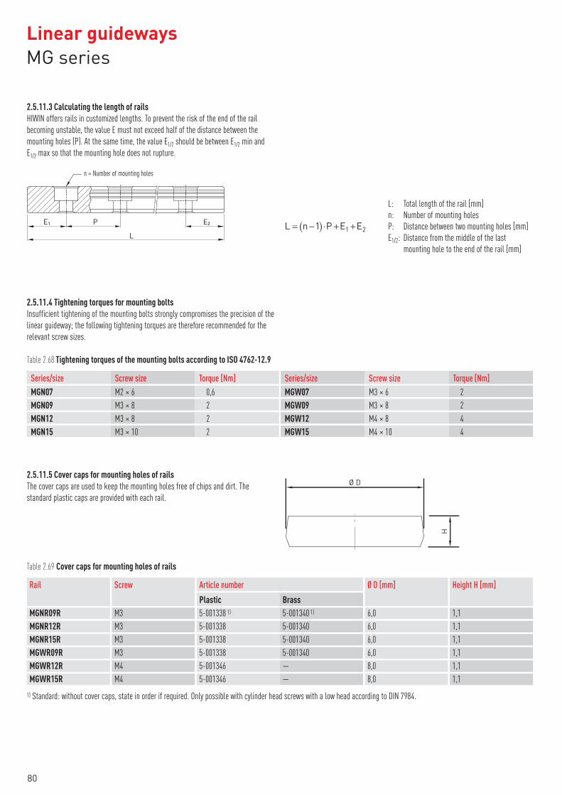
2.5.11.3 Calculating the length of rails
HIWIN offers rails in customized lengths. To prevent the risk of the end of the rail
becoming unstable, the value E must not exceed half of the distance between the
mounting holes (P). At the same time, the value E1/2 should be between E1/2 min and
E1/2 max so that the mounting hole does not rupture.
L: Total length of the rail [mm]
n: Number of mounting holes
P: Distance between two mounting holes [mm]
E1/2: Distance from the middle of the last
mounting hole to the end of the rail [mm]
E1 P
L
E2
n = Number of mounting holes
2.5.11.4 Tightening torques for mounting bolts
Insufficient tightening of the mounting bolts strongly compromises the precision of the
linear guideway; the following tightening torques are therefore recommended for the
relevant screw sizes.
Table 2.68 Tightening torques of the mounting bolts according to ISO 4762-12.9
MGN07 M2 × 6 0,6
MGN09 M3 × 8 2
MGN12 M3 × 8 2
MGN15 M3 × 10 2
Series/size Screw size Torque [Nm] Series/size Screw size Torque [Nm]MGW07 M3 × 6 2
MGW09 M3 × 8 2
MGW12 M4 × 8 4
MGW15 M4 × 10 4
2.5.11.5 Cover caps for mounting holes of rails
The cover caps are used to keep the mounting holes free of chips and dirt. The
standard plastic caps are provided with each rail.
Ø D
H
Table 2.69 Cover caps for mounting holes of rails
Rail ScrewPlastic Brass
Article number Ø D [mm] Height H [mm]
MGNR09R M3 5-001338 1) 5-001340 1) 6,0 1,1
MGNR12R M3 5-001338 5-001340 6,0 1,1
MGNR15R M3 5-001338 5-001340 6,0 1,1
MGWR09R M3 5-001338 5-001340 6,0 1,1
MGWR12R M4 5-001346 — 8,0 1,1
MGWR15R M4 5-001346 — 8,0 1,1
1) Standard: without cover caps, state in order if required. Only possible with cylinder head screws with a low head according to DIN 7984.
Linear guidewaysMG series
80

2.5.12 Dust protection
The blocks of the MG series are equipped on both sides with an end seal to protect
against dirt as standard. Additional seals can be fitted underneath on the side of the
block. Bottom seals can be ordered using the “+U” identifier in the article number.
They are available as options for sizes 12 and 15. They cannot be fitted for sizes 7 and
9 due to the limited installation space H1. When fitting a bottom seal, the side
mounting surface of the rail must not exceed H1.
H1
Table 2.70 Installation space H1
MGN07 — —
MGN09 — —
MGN12 • 2,0
MGN15 • 3,0
Series/size Bottom seal H1 Series/size Bottom seal H1
MGW07 — —
MGW09 — —
MGW12 • 2,6
MGW15 • 2,6
2.5.13 Friction
The table shows the maximum frictional resistance of the seals of a block. The values
indicated apply to blocks on uncoated rails. Higher friction forces occur on coated
rails.
Table 2.71 Frictional resistance for standard block
MGN07 0,1
MGN09 0,1
MGN12 0,2
MGN15 0,2
Series/size Friction force [N] Series/size Friction force [N]MGW07 0,2
MGW09 0,2
MGW12 0,3
MGW15 0,3
81

2.5.14 Tolerances depending on accuracy class
The MG series are available in three accuracy classes depending on parallelism
between block and rail, height accuracy H and accuracy of width N. The choice of
accuracy class is determined by the machine requirements.
W
H
N
B
A D
C
2.5.14.1 Parallelism
Parallelism of stop surfaces D and B of block and rail and parallelism of top of block
C to mounting surface A of rail. Ideal linear guideway installation is required, as is a
measurement in the centre of the block.
Table 2.72 Tolerance of parallelism between block and rail
– 50 12 6 2
50 – 80 13 7 3
80 – 125 14 8 3,5
125 – 200 15 9 4
200 – 250 16 10 5
250 – 315 17 11 5
Rail length [mm] Accuracy classC H P
Rail length [mm] Accuracy classC H P
315 – 400 18 11 6
400 – 500 19 12 6
500 – 630 20 13 7
630 – 800 22 14 8
800 – 1000 23 16 9
1000 – 1200 25 18 11
Unit: µm
2.5.14.2 Accuracy – height and width
Height tolerance H
Permissible absolute dimension variance of height H, measured between centre of
screw-on surface C and underside of rail A, with block in any position on the rail.
Width tolerance N
Permissible absolute dimension variance of width N, measured between centre of
screw-on surfaces D and B, with block in any position on the rail.
Height variance of H
Permissible variance of height H between several blocks on a rail, measured in the
same rail position.
Width variance of N
Permissible variance of width N between several blocks on a rail, measured in the
same rail position.
Table 2.73 Height and width tolerances of non-interchangeable models
Series/size Accuracy class Height tolerance of H Width tolerance of N Height variance of H Width variance of N
MG_07 –
MG_15
Normal (C) ± 0,04 ± 0,04 0,03 0,03
High (H) ± 0,02 ± 0,025 0,015 0,02
Precision (P) ± 0,01 ± 0,015 0,007 0,01
Unit: mm
Table 2.74 Height and width tolerances of interchangeable types
Series/size Accuracy class Height tolerance of H Width tolerance of N Height variance of H Width variance of N Height variance of H 1)
MG_07 –
MG_15
Normal (N) ± 0,04 ± 0,04 0,03 0,03 0,07
High (H) ± 0,02 ± 0,025 0,015 0,02 0,04
Precision (P) ± 0,01 ± 0,015 0,007 0,01 0,02
Unit: mm1) Permissible deviation of height H between several blocks on a pair of rails
Linear guidewaysMG series
82

2.5.15 Permissible mounting surface tolerances
Once the requirements relating to the accuracy of the mounting surfaces are met, the
good accuracy, rigidity and lifetime of the MG series linear guideways are achieved. S1
P
(200)
Parallelism of the reference surface (P)
Table 2.75 Maximum tolerance for parallelism (P)
Series/size
ZF Z0 Z1
Preload class
MG_07 3 3 3
MG_09 4 4 3
MG_12 9 9 5
MG_15 10 10 6
Unit: μm
Table 2.76 Maximum tolerance for height of reference surface (S1)
Series/size
ZF Z0 Z1
Preload class
MG_07 25 25 3
MG_09 35 35 6
MG_12 50 50 12
MG_15 60 60 20
Unit: μm
Table 2.77 Requirements for the mounting surface
Series/size Required evenness of the mounting surface
MG_07 0,025/200
MG_09 0,035/200
MG_12 0,050/200
MG_15 0,060/200
Note: The values in the table are applicable to the preload classes ZF and Z0. For Z1 or if more than one rail is to be mounted on the same surface, the table values must be at
least halved.
83

2.5.16 Shoulder heights and fillets
Imprecise shoulder heights and fillets of mounting surfaces compromise precision and
may lead to conflicts with the block or rail profiles. The following shoulder heights and
edge profiles must be observed in order to avoid assembly problems.
r2
r1
H2
H1
Table 2.78 Shoulder heights and fillets
Series/size Max. edgeradius r1
Max. edgeradius r2
Shoulder height of H1 Shoulder height of H2
MGN07 0,2 0,2 1,2 3
MGN09 0,2 0,3 1,7 3
MGN12 0,3 0,4 1,7 4
MGN15 0,5 0,5 2,5 5
MGW07 0,2 0,2 1,7 3
MGW09 0,3 0,3 2,5 3
MGW12 0,4 0,4 3 4
MGW15 0,4 0,8 3 5
Unit: mm
Linear guidewaysMG series
84

2.6 Linear guideway, series PM
2.6.1 Properties of the linear guideway, series PMN
The HIWIN linear guideway of the PMN series is based on the proven MGN series.
Thanks to the optimised ball return in the plastic duct, the synchronous performance
and quiet running are improved and the weight is reduced by around 20 %. The Gothic
race profile absorbs loads in all directions and is particularly rigid and precise. Given
its compact and lightweight design, it is particularly suited to use in small devices.
2.6.2 Structure of the PMN series
Fig. Structure of the PMN series
○�2-row recirculation ball bearing guide
○�Gothic arch contact design
○�Stainless steel block and balls
○�Rails made from standard or stainless steel
○�Compact and lightweight design
○�Balls are secured in the block by retaining wire
○�End seal
○�Interchangeable models are available in defined accuracy classes
○�Optimized ball deflection
○�Improved synchronous performance
○�Reduced weight
2.6.3 Applications of the PM series
The PM series was developed for use in restricted spaces, e.g. in the semiconductor
industry, PCB population, medical technology, robot applications, measurement de-
vices, office automation and other sectors needing miniature guides.
85

2.6.4 Article numbers of the PM series
For PM linear guideways, a distinction is made between interchangeable and non-
interchangeable models. The dimensions of both models are the same. The main
difference is that the block and rail in the interchangeable models can be freely
interchanged. Block and rail can therefore be ordered separately and fitted by the
customer.
Given their stringent dimensional accuracy check, the interchangeable modules are a
good choice for customers who do not use rails in pairs on one axis. The article num-
bers include the dimensions, model, accuracy class, preload etc.
2.6.4.1 Non-interchangeable models (custom-assembled)
○�Article number of the fully assembled linear guideway
PMN 12 C 2 R1600 Z1 H M 2
Series:PMN
Size: 5, 9, 12
Load type:C: average loadH: high load
Number of blocks per rail
Rail length [mm]
Preload ID: ZF 2) 3), ZO, Z1
Accuracy class:C, H, P
None: standard steel (rail only)M: stainless steel
Rails per axis set 1)
2.6.4.2 Interchangeable models
○�Article number of PM block
PMN 12 C Z1 H M
Series:PMN
Size: 5, 9, 12
Load type:C: average loadH: high load
Preload ID:ZF 2), ZO, Z1
Accuracy class: C, H, P
M: stainless steel
○�Article number of PM rail
PMN R 12 R1000 H M
Series:PMN
Rail
Size: 5, 9, 12Rail length [mm]
Accuracy class: C, H, P
None: standard steelM: stainless steel
Note:1) The figure 2 is also a quantity, i.e. one item of the above-mentioned article consists of a pair of rails. No number is specified for individual rails.2) Not available for size 5.3) Not available for paired rails.
Linear guidewaysPM series
86

2.6.5 Preload
The PM series offers three preload classes for various applications.
Table 2.79 Preload ID
ID Preload Accuracy class
ZF 1) Slight play: 4 – 10 μm C, H
Z0 Zero-play, very slight preload C – P
Z1 Slight preload: 0 – 0,02 Cdyn C – P
1) Not available for size 5
2.6.6 Load ratings and torques
MX MY MZ
Table 2.80 Load ratings and torques for PM series
Series/size Dynamic loadrating Cdyn [N]*
Static loadrating C0 [N]
MX MY MZ
Dynamic moment [Nm]
M0X M0Y M0Z
Static moment [Nm]
PMN05C 540 840 1,3 0,8 0,8 2,0 1,3 1,3
PMN05H 667 1089 2,5 2,2 2,2 2,6 2,3 2,3
PMN09C 2010 2840 9,2 6,3 6,3 13,0 9,0 9,0
PMN12C 2840 3920 18,5 9,9 9,9 25,5 13,7 13,7
* Dynamic load rating for travel distance of 50 000 m
87

2.6.7 Dimensions of the PM blocks
2.6.7.1 PMN
WR
WR
L1
L1
B1
B1
H2
H2
HR
HR
hh
Gn
Gn
H1
H1
HH
N
N
W
W
L
L
ØD
ØD
Ød
Ød
E
E E
EP
P
CB
B
4–M×l
2–M×l
PMN05
PMN09, PMN12
Table 2.81 Dimensions of the block
Series/size
H H1 N
Installation dimensions[mm]
W B B1 C L1 L Gn M × l H2
Dimensions of the block[mm]
Cdyn C0
Load ratings [N] Weight[kg]
PMN05C6 1,5 3,5 12 8 2 —
9,6 16Ø0,8 M2 × 1,5 1,0
540 840 0,008
PMN05H 12,6 19 667 1089 0,010
PMN09C 10 2,2 5,5 20 15 2,5 10 19,4 30 Ø1,4 M3 × 3 1,8 2010 2840 0,012
PMN12C 13 3,0 7,5 27 20 3,5 15 22 35 Ø2 M3 × 3,5 2,5 2840 3920 0,025
For dimensions of rail, see page 89, for standard and optional lubrication adapter, see page 117.
Linear guidewaysPM series
88

2.6.8 Dimensions of the PM rail
2.6.8.1 Dimensions of PMN_R
L
h
PE1 E2
WR
HR
Ød
ØD
Table 2.82 Dimensions of rail PMN_R
Series/size
Assembly screwfor rail [mm]
WR HR D h d P
Dimensions of rail [mm] Max. length[mm]
Max. lengthE1 = E2
E1/2 min[mm]
E1/2 max[mm]
Weight[kg/m]
PMNR05R M2 × 6 5 3,6 3,6 0,8 2,4 15,0 250 225 4 11 0,15
PMNR09R M3 × 8 9 6,5 6,0 3,5 3,5 20,0 1200 1180 5 15 0,38
PMNR12R M3 × 8 12 8,0 6,0 4,5 3,5 25,0 2000 1975 5 20 0,65
The special screws needed for mounting rail PMN05R are delivered with the rail order.
Note:
1. The tolerance for E is +0.5 to –1.0 mm for standard rails and 0 to –0.3 mm for joints.
2. If the E1/2 dimensions are not indicated, the maximum possible number of mounting holes will be determined under consideration of E1/2 min.
3. The rails are shortened to the required length. If the E1/2 dimensions are not indicated, these will be carried out symmetrically.
2.6.8.2 Calculating the length of rails
HIWIN offers rails in customised lengths. To prevent the risk of the end of the rail
becoming unstable, the value E must not exceed half of the distance between the
mounting holes (P). At the same time, the value E1/2 should be between E1/2 min and
E1/2 max so that the mounting hole does not rupture.
L: Total length of the rail [mm]
n: Number of mounting holes
P: Distance between two mounting holes [mm]
E1/2: Distance from the middle of the last
mounting hole to the end of the rail [mm]
E1 P
L
E2
n = Number of mounting holes
2.6.8.3 Tightening torques for mounting bolts
Insufficient tightening of the mounting bolts strongly compromises the precision of the
linear guideway; the following tightening torques are therefore recommended for the
relevant screw sizes.
Table 2.83 Tightening torques of the mounting bolts according to ISO 4762-12.9
PMN05 M2 × 6 0,6
PMN09 M3 × 8 2,0
Series/size Screw size Torque [Nm] Series/size Screw size Torque [Nm]PMN12 M3 × 8 2,0
89

2.6.8.4 Cover caps for mounting holes of rails
The cover caps are used to keep the mounting holes free of chips and dirt. The stand-
ard plastic caps are provided with each rail.
Ø D
H
Table 2.84 Cover caps for mounting holes of rails
Rail ScrewPlastic Brass
Article number Ø D [mm] Height H [mm]
PMNR05R — — — — —
PMNR09R M3 5-001338 1) 5-001340 1) 6,0 1,1
PMNR12R M3 5-001338 5-001340 6,0 1,1
1) Standard without cover caps, state in order if required. Only possible with cylinder head screws with a low head according to DIN 7984.
2.6.9 Dust protection
The blocks of the PM series are equipped on both sides with an end seal to protect
against dirt as standard. Additional seals can be fitted underneath on the side of the
block. Bottom seals can be ordered using the “+U” identifier in the article number.
They are available as options for sizes 9 and 12. They cannot be fitted for size 5 due to
the limited installation space H1. When fitting a bottom seal, the side mounting
surface of the rail must not exceed H1.
H1
Table 2.85 Installation space H1
PMN05 — —
PMN09 • 1,2
Series/size Bottom seal H1 Series/size Bottom seal H1
PMN12 • 2,0
2.6.10 Friction
The table shows the maximum frictional resistance of the seals of a block. The values
indicated apply to blocks on uncoated rails. Higher friction forces occur on coated
rails.
Table 2.86 Frictional resistance for standard block
PMN05 0,1
PMN09 0,1
Series/size Friction force [N] Series/size Friction force [N]PMN12 0,2
Linear guidewaysPM series
90

2.6.11 Tolerances depending on accuracy class
The PM series are available in three accuracy classes depending on parallelism
between block and rail, height accuracy H and accuracy of width N. The choice of
accuracy class is determined by the machine requirements.
W
H
N
B
A D
C
2.6.11.1 Parallelism
Parallelism of stop surfaces D and B of block and rail and parallelism of top of block
C to mounting surface A of rail. Ideal linear guideway installation is required, as is a
measurement in the centre of the block.
Table 2.87 Tolerance of parallelism between block and rail
– 50 12 6 2
50 – 80 13 7 3
80 – 125 14 8 3,5
125 – 200 15 9 4
200 – 250 16 10 5
250 – 315 17 11 5
315 – 400 18 11 6
400 – 500 19 12 6
500 – 630 20 13 7
630 – 800 22 14 8
800 – 1000 23 16 9
Rail length [mm] Accuracy classC H P
Rail length [mm] Accuracy classC H P
1000 – 1200 25 18 11
1200 – 1300 25 18 11
1300 – 1400 26 19 12
1400 – 1500 27 19 12
1500 – 1600 28 20 13
1600 – 1700 29 20 14
1700 – 1800 30 21 14
1800 – 1900 30 21 15
1900 – 2000 31 22 15
2000 – 31 22 16
Unit: µm
91

2.6.11.2 Accuracy – height and width
Height tolerance H
Permissible absolute dimension variance of height H, measured between centre of
screw-on surface C and underside of rail A, with block in any position on the rail.
Width tolerance N
Permissible absolute dimension variance of width N, measured between centre of
screw-on surfaces D and B, with block in any position on the rail.
Height variance of H
Permissible variance of height H between several blocks on a rail, measured in the
same rail position.
Width variance of N
Permissible variance of width N between several blocks on a rail, measured in the
same rail position.
Table 2.88 Height and width tolerances of non-interchangeable models
Series/size Accuracy class Height tolerance of H Width tolerance of N Height variance of H Width variance of N
PMN05 –
PMN12
Normal (C) ± 0,04 ± 0,04 0,03 0,03
High (H) ± 0,02 ± 0,025 0,015 0,02
Precision (P) ± 0,01 ± 0,015 0,007 0,01
Unit: mm
Table 2.89 Height and width tolerances of interchangeable types
Series/size Accuracy class Height tolerance of H Width tolerance of N Height variance of H Width variance of N Height variance of H 1)
PMN05 –
PMN12
Normal (N) ± 0,04 ± 0,04 0,03 0,03 0,07
High (H) ± 0,02 ± 0,025 0,015 0,02 0,04
Precision (P) ± 0,01 ± 0,015 0,007 0,01 0,02
Unit: mm1) Permissible deviation of height H between several blocks on a pair of rails
2.6.12 Permissible mounting surface tolerances
Once the requirements relating to the accuracy of the mounting surfaces are met, the
good accuracy, rigidity and lifetime of the PM series linear guideways are achieved. S1
P
(200)
Parallelism of the reference surface (P)
Table 2.90 Maximum tolerance for parallelism (P)
Series/size
ZF Z0 Z1
Preload class
PM_05 2 2 2
PM_09 4 4 3
PM_12 9 9 5
Unit: μm
Linear guidewaysPM series
92

Table 2.91 Maximum tolerance for height of reference surface (S1)
Series/size
ZF Z0 Z1
Preload class
PM_05 20 20 2
PM_09 35 35 6
PM_12 50 50 12
Unit: μm
Table 2.92 Requirements for the mounting surface
Series/size Required evenness of the mounting surface
PM_05 0,015/200
PM_09 0,035/200
PM_12 0,050/200
Unit: mm
Note: The values in the table are applicable to the preload classes ZF and Z0. For Z1 or if more than one rail is to be mounted on the same surface, the table values must be at
least halved.
2.6.13 Shoulder heights and fillets
Imprecise shoulder heights and fillets of mounting surfaces compromise precision and
may lead to conflicts with the block or rail profiles. The following shoulder heights and
edge profiles must be observed in order to avoid assembly problems.
r2
r1
H2
H1
Table 2.93 Shoulder heights and fillets
Series/size Max. edgeradius r1
Max. edgeradius r2
Shoulder height of H1 Shoulder height of H2
PMN05 0,1 0,2 1,2 2
PMN09 0,2 0,3 1,7 3
PMN12 0,3 0,4 1,7 4
Unit: mm
93

2.7 Linear guideway, series RG and QR
2.7.1 Properties of the linear guideways, series RG and QR
The HIWIN linear guideways of the RG series use rollers rather than balls as rolling
elements. The RG series provides extremely good rigidity and very good loading
capacity. It is designed with a 45° contact angle. Its linear contact surface greatly
reduces deformation from the loading produced and therefore ensures very good
rigidity and loading capacity in all 4 loading directions. The linear guides of the RG
series are therefore ideal for use in high-precision manufacturing.
The models of the QR series with SynchMotion™ technology offer all the positive
properties of the standard series RG. Controlled movement of the rollers at a defined
distance also results in improved synchronous performance, higher reliable travel
speeds, extended lubrication intervals and less running noise. Since the installation
dimensions of the QR blocks are identical to those of the RG blocks, they are also
fitted on the RGR standard rail and can therefore be interchanged with ease. For more
information, refer to page 22.
2.7.2 Structure of the RG/QR series
○�4-row recirculation roller bearing guide
○�45° contact angle
○�Ball retainers prevent the rollers from falling out when the block is removed
○�Various sealing variants depending on the field of application
○�6 options for connecting grease nipple and lubrication adapter
○�SynchMotion™ technology (QR series)
Fig. Structure of the QR seriesFig. Structure of the RG series
2.7.3 Advantages
○�Zero play
○�Interchangeable
○�Very high load ratings
○�Very high rigidity
○�Low displacement forces even with high preload
Additional advantages of QR series
○�Improved synchronous performance
○�Optimized for higher travel speeds
○�Extended lubrication intervals
○�Less running noise
2.7.4 Article numbers of the RG/QR series
For RG/QR linear guideways, a distinction is made between interchangeable and non-
interchangeable models. The dimensions of both models are the same. The main differ-
ence is that the block and rail in the interchangeable models can be freely inter-
changed. The article numbers of the series include the dimensions, model, accuracy
class, preload etc.
Linear guidewaysRG/QR series
94

2.7.4.1 Non-interchangeable models (custom-assembled)
○�Article number of the fully assembled linear guideway
RG W 35 C C 2 R 1640 ZA P 2 KK E2
Series:RGQR
Block type:W: flange blockH: square block
Size:RG: 15, 20, 25, 30, 35, 45, 55, 65QR: 25, 30, 35, 45
Load type:C: heavy loadH: super heavy load
Block mounting:A: from aboveC: from above or below
Number of blocks per rail
Rail mounting:R: from aboveT: from below
Rail length [mm]
Preload ID: ZO, ZA, ZB
Accuracy class:H, P, SP, UP
Rails per axis set 1)
Dust protection 2):None: standard (SS)ZZ, DD, KK, SW 3), ZWX 3)
None: standardE2: oil lubrication unit 3)
2.7.4.2 Interchangeable models
○�Article number of RG/QR block
RG W 25 C C ZA H ZZ E2
Series:RGQR
Block type:W: flange blockH: square block
Size:RG: 15, 20, 25, 30, 35, 45, 55, 65QR: 25, 30, 35, 45
Load type:C: heavy loadH: super heavy load
Block mounting:A: from aboveC: from above or below
Preload ID: ZO, ZA, ZB
Accuracy class: H, P
Dust protection 2):None: standard (SS)ZZ, DD, KK, SW 3), ZWX 3)
None: standardE2: oil lubrication unit 3)
○�Article number of RG rail
RG R 25 R 1240 H
RG series
Rail
Size: 15, 20, 25, 30, 35, 45, 55, 65Rail mounting:R: from aboveT: from below
Rail length [mm]
Accuracy class: H
Note:1) The figure 2 is also a quantity, i.e. one item of the above-mentioned article consists of a pair of rails. No number is specified for individual rails.2) You will find an overview of the individual sealing systems on page 20.3) Only available for RG
95

2.7.5 Block types
HIWIN provides square and flange blocks for the linear guideways. Given their low
height and large mounting surface, flange blocks are suited to large loads.
Table 2.94 Block types
Type Series/size
Structure Height[mm]
Rail length[mm]
Typical application
Square typeRGH-CA
RGH-HA28 – 90
100 – 4.000
○�Automation technology
○�Transport technology
○�CNC machining centers
○�High-performance cutting machines
○�CNC grinding machines
○�Injection moulding machines
○�Portal milling machines
○�Machines and systems requiring high
rigidity
○�Machines and systems requiring high
load rating
○�Spark erosion machines
Flange typeRGW-CC
RGW-HC24 – 90
2.7.6 Rail types
In addition to rails with standard fastening from above, HIWIN also provides rails for
fastening from below.
Table 2.95 Rail types
Fastening from above Fastening from below
RGR_R RGR_T
Linear guidewaysRG/QR series
96

2.7.7 Preload
2.7.7.1 Definition
Every rail type can be preloaded. Oversized rollers are used for this purpose. Normally a
linear guideway has negative clearance between track and rollers to increase rigidity
and precision. The linear guideways of the RG/QR series offer three standard preloads
for various applications and conditions.
P = 0,07 Cdyn 2,8 P
Z0
Elastic deformation
without preload
ZB
Elastic deformation
with high preload
Operating load
Elas
tic d
efor
mat
ion
2.7.7.2 Preload ID
Table 2.96 Preload ID
ID Preload Application
ZO Light preload 0,02 – 0,04 Cdyn Constant load direction, little impact, low precision required
ZA Medium preload 0,07 – 0,09 Cdyn High precision needed
ZB High preload 0,12 – 0,14 Cdyn Very high rigidity required, with vibration and impact
The diagram shows the relationship between rigidity, frictional resistance and nominal
lifetime. For smaller models, a preload of no more than ZA is recommended to avoid
the lifetime being shortened as a result of preload.Rigidity
Friction
Lifetime
ZBZAZ0
97

2.7.8 Load ratings and torques
MX MY MZ
Table 2.97 Load ratings and torques for series RG/QR
Series/size Dynamic loadrating Cdyn [N]*
Static loadrating C0 [N]
MX MY MZ
Dynamic moment [Nm]
MOX MOY MOZ
Static moment [Nm]
RG_15C 11300 24000 147 82 82 311 173 173
RG_20C 21300 46700 296 210 210 647 460 460
RG_20H 26900 63000 373 358 358 872 837 837
RG_25C 27700 57100 367 293 293 758 605 605
QR_25C 38500 54400 511 444 444 722 627 627
RG_25H 33900 73400 450 457 457 975 991 991
QR_25H 44700 65300 594 621 621 867 907 907
RG_30C 39100 82100 688 504 504 1445 1060 1060
QR_30C 51500 73000 906 667 667 1284 945 945
RG_30H 48100 105000 845 784 784 1846 1712 1712
QR_30H 64700 95800 1138 1101 1101 1685 1630 1630
RG_35C 57900 105200 1194 792 792 2170 1440 1440
QR_35C 77000 94700 1590 1083 1083 1955 1331 1331
RG_35H 73100 142000 1508 1338 1338 2930 2600 2600
QR_35H 95700 126300 1975 1770 1770 2606 2335 2335
RG_45C 92600 178800 2340 1579 1579 4520 3050 3050
QR_45C 123200 156400 3119 2101 2101 3959 2666 2666
RG_45H 116000 230900 3180 2748 2748 6330 5470 5470
QR_45H 150800 208600 3816 3394 3394 5278 4694 4694
RG_55C 130500 252000 4148 2796 2796 8010 5400 5400
RG_55H 167800 348000 5376 4942 4942 11150 10250 10250
RG_65C 213000 411600 8383 5997 5997 16200 11590 11590
RG_65H 275300 572700 10839 10657 10657 22550 22170 22170
* Dynamic load rating for travel distance of 100 000 m
Linear guidewaysRG/QR series
98

2.7.9 Rigidity
Rigidity depends on preload. The adjacent formula can be used to determine
deformation depending on rigidity.
: Deformation [μm]
P: Operating load [N]
k: Rigidity [N/μm]
Table 2.98 Radial rigidity for series RG/QR
Load class Series/size
ZO ZA ZB
Rigidity depending on preload
Heavy load RG_15C 482 504 520
RG_20C 586 614 633
RG_25C 682 717 740
QR_25C 616 645 665
RG_30C 809 849 876
QR_30C 694 726 748
RG_35C 954 1002 1035
QR_35C 817 856 882
RG_45C 1433 1505 1554
QR_45C 1250 1310 1350
RG_55C 1515 1591 1643
RG_65C 2120 2227 2300
Super heavy load RG_20H 786 823 848
RG_25H 873 917 947
QR_25H 730 770 790
RG_30H 1083 1136 1173
QR_30H 910 950 980
RG_35H 1280 1344 1388
QR_35H 1090 1140 1170
RG_45H 1845 1938 2002
QR_45H 1590 1660 1720
RG_55H 2079 2182 2254
RG_65H 2931 3077 3178
Unit: N⁄μm
99

2.7.10 Dimensions of the RG/QR blocks
2.7.10.1 RGH/QRH
WR
K2L1
K1
H3
B1
H2
H1
H
T
N
W G L
C
B
6–M×l
Table 2.99 Dimensions of the block
Series/size
H H1 N
Installationdimensions [mm]
W B B1 C L1 L K1 K2 G M × l T H2 H3
Dimensions of the block [mm]
Cdyn C0
Load ratings [N] Weight[kg]
RGH15CA 28 4,0 9,5 34 26,0 4,0 26 45,0 68,0 13,40 4,70 5,3 M4 × 8 6,0 7,60 10,1 11300 24000 0,20
RGH20CA34 5,0 12,0 44 32,0 6,0
36 57,5 86,0 15,806,00 5,3 M5 × 8 8,0 8,30 8,3
21300 46700 0,40
RGH20HA 50 77,5 106,0 18,80 26900 63000 0,53
RGH25CA40 5,5 12,5 48 35,0 6,5
35 64,5 97,9 20,757,25 12,0 M6 × 8 9,5 10,20 10,0
27700 57100 0,61
RGH25HA 50 81,0 114,4 21,50 33900 73400 0,75
QRH25CA40 5,5 12,5 48 35,0 6,5
35 66,0 97,9 20,757,25 12,0 M6 × 8 9,5 10,20 10,0
38500 54400 0,60
QRH25HA 50 81,0 112,9 21,50 44700 65300 0,74
RGH30CA45 6,0 16,0 60 40,0 10,0
40 71,0 109,8 23,508,00 12,0 M8 × 10 9,5 9,50 10,3
39100 82100 0,90
RGH30HA 60 93,0 131,8 24,50 48100 105000 1,16
QRH30CA45 6,0 16,0 60 40,0 10,0
40 71,0 109,8 23,508,00 12,0 M8 × 10 9,5 9,50 10,3
51500 73000 0,89
QRH30HA 60 93,0 131,8 24,50 64700 95800 1,15
RGH35CA55 6,5 18,0 70 50,0 10,0
50 79,0 124,0 22,5010,00 12,0 M8 × 12 12,0 16,00 19,6
57900 105200 1,57
RGH35HA 72 106,5 151,5 25,25 73100 142000 2,06
QRH35CA55 6,5 18,0 70 50,0 10,0
50 79,0 124,0 22,5010,00 12,0 M8 × 12 12,0 16,00 19,6
77000 94700 1,56
QRH35HA 72 106,5 151,5 25,25 95700 126300 2,04
RGH45CA70 8,0 20,5 86 60,0 13,0
60 106,0 153,2 31,0010,00 12,9 M10 × 17 16,0 20,00 24,0
92600 178800 3,18
RGH45HA 80 139,8 187,0 37,90 116000 230900 4,13
QRH45CA70 8,0 20,5 86 60,0 13,0
60 106,0 153,2 31,0010,00 12,9 M10 × 17 16,0 20,00 24,0
123200 156400 3,16
QRH45HA 80 139,8 187,0 37,90 150800 208600 4,10
RGH55CA80 10,0 23,5 100 75,0 12,5
75 125,5 183,7 37,7512,50 12,9 M12 × 18 17,5 22,00 27,5
130500 252000 4,89
RGH55HA 95 173,8 232,0 51,90 167800 348000 6,68
RGH65CA90 12,0 31,5 126 76,0 25,0
70 160,0 232,0 60,8015,80 12,9 M16 × 20 25,0 15,00 15,0
213000 411600 8,89
RGH65HA 120 223,0 295,0 67,30 275300 572700 12,13
For dimensions of rail, see page 102, for standard and optional lubrication adapter, see page 117.
Linear guidewaysRG/QR series
100

2.7.10.2 RGW/QRW
WR
K2L1
K1
C1
H3
B1
H2
H1
T 1H
T
N
W G L
C
B
6–M
Table 2.100 Dimensions of the block
Series/size
H H1 N
Installationdimensions [mm]
W B B1 C C1 L1 L K1 K2 G M T T1 H2 H3
Dimensions of the block [mm]
Cdyn C0
Load ratings [N] Weight[kg]
RGW15CC 24 4,0 16,0 47 38 4,5 30 26 45,0 68,0 11,40 4,70 5,3 M5 6,0 7 3,60 6,1 11300 24000 0,22
RGW20CC30 5,0 21,5 63 53 5 40 35
57,5 86,0 13,806,00 5,3 M6 8,0 10 4,30 4,3
21300 46700 0,47
RGW20HC 77,5 106,0 23,80 26900 63000 0,63
RGW25CC36 5,5 23,5 70 57 6,5 45 40
64,5 97,9 15,757,25 12,0 M8 9,5 10 6,20 6,0
27700 57100 0,72
RGW25HC 81,0 114,4 24,00 33900 73400 0,91
QRW25CC36 5,5 23,5 70 57 6,5 45 40
66,0 97,9 15,757,25 12,0 M8 9,5 10 6,20 6,0
38500 54400 0,71
QRW25HC 81,0 112,9 24,00 44700 65300 0,90
RGW30CC42 6,0 31,0 90 72 9 52 44
71,0 109,8 17,508,00 12,0 M10 9,5 10 6,50 7,3
39100 82100 1,16
RGW30HC 93,0 131,8 28,50 48100 105000 1,52
QRW30CC42 6,0 31,0 90 72 9 52 44
71,0 109,8 17,508,00 12,0 M10 9,5 10 6,50 7,3
51500 73000 1,15
QRW30HC 93,0 131,8 28,50 64700 95800 1,51
RGW35CC48 6,5 33,0 100 82 9 62 52
79,0 124,0 16,5010,00 12,0 M10 12,0 13 9,00 12,6
57900 105200 1,75
RGW35HC 106,5 151,5 30,25 73100 142000 2,40
QRW35CC48 6,5 33,0 100 82 9 62 52
79,0 124,0 16,5010,00 12,0 M10 12,0 13 9,00 12,6
77000 94700 1,74
QRW35HC 106,5 151,5 30,25 95700 126300 2,38
RGW45CC60 8,0 37,5 120 100 10 80 60
106,0 153,2 21,0010,00 12,9 M12 14,0 15 10,00 14,0
92600 178800 3,43
RGW45HC 139,8 187,0 37,90 116000 230900 4,57
QRW45CC60 8,0 37,5 120 100 10 80 60
106,0 153,2 21,0010,00 12,9 M12 14,0 15 10,00 14,0
123200 156400 3,41
QRW45HC 139,8 187,0 37,90 150800 208600 4,54
RGW55CC70 10,0 43,5 140 116 12 95 70
125,5 183,7 27,7512,50 12,9 M14 16,0 17 12,00 17,5
130500 252000 5,43
RGW55HC 173,8 232,0 51,90 167800 348000 7,61
RGW65CC90 12,0 53,5 170 142 14 110 82
160,0 232,0 40,8015,80 12,9 M16 22,0 23 15,00 15,0
213000 411600 11,63
RGW65HC 223,0 295,0 72,30 275300 572700 16,58
For dimensions of rail, see page 102, for standard and optional lubrication adapter, see page 117.
101

2.7.11 Dimensions of the RG rail
The RG rails are used for both the RG and QR blocks.
2.7.11.1 Dimensions of RGR_R
WR
ØD
Ød
HR
h
E1 E2PL
Table 2.101 Dimensions of rail RGR_R
Series/size
Assembly screwfor rail [mm]
WR HR D h d P
Dimensions of rail [mm] Max. length[mm]
Max. lengthE1 = E2
E1/2 min[mm]
E1/2 max[mm]
Weight[kg/m]
RGR15R M4 × 16 15 16,5 7,5 5,7 4,5 30,0 4000 3960 6 24 1,70
RGR20R M5 × 20 20 21,0 9,5 8,5 6,0 30,0 4000 3960 7 23 2,66
RGR25R M6 × 20 23 23,6 11,0 9,0 7,0 30,0 4000 3960 8 22 3,08
RGR30R M8 × 25 28 28,0 14,0 12,0 9,0 40,0 4000 3920 9 31 4,41
RGR35R M8 × 25 34 30,2 14,0 12,0 9,0 40,0 4000 3920 9 31 6,06
RGR45R M12 × 35 45 38,0 20,0 17,0 14,0 52,5 4000 3937,5 12 40,5 9,97
RGR55R M14 × 45 53 44,0 23,0 20,0 16,0 60,0 4000 3900 14 46 13,98
RGR65R M16 × 50 63 53,0 26,0 22,0 18,0 75,0 4000 3900 15 60 20,22
2.7.11.2 Dimensions RGR_T (rail mounting from below)
WRS
HR
h
E1 E2P
L
Table 2.102 Dimensions of rail RGR_T
Series/size
WR HR S h P
Dimensions of rail [mm] Max. length[mm]
Max. lengthE1 = E2
E1/2 min[mm]
E1/2 max[mm]
Weight[kg/m]
RGR15T 15 16,5 M5 8,0 30,0 4000 3960 6 24 1,86
RGR20T 20 21,0 M6 10,0 30,0 4000 3960 7 23 2,76
RGR25T 23 23,6 M6 12,0 30,0 4000 3960 8 22 3,36
RGR30T 28 28,0 M8 15,0 40,0 4000 3920 9 31 4,82
RGR35T 34 30,2 M8 17,0 40,0 4000 3920 9 31 6,48
RGR45T 45 38,0 M12 24,0 52,5 4000 3937,5 12 40,5 10,83
RGR55T 53 44,0 M14 24,0 60,0 4000 3900 14 46 15,15
RGR65T 63 53,0 M20 30,0 75,0 4000 3900 15 60 21,24
Note:
1. The tolerance for E is +0.5 to –1 mm for standard rails and 0 to –0.3 mm for joints.
2. If the E1/2 dimensions are not indicated, the maximum possible number of mounting holes will be determined under consideration of E1/2 min.
3. The rails are shortened to the required length. If the E1/2 dimensions are not indicated, these will be carried out symmetrically.
Linear guidewaysRG/QR series
102

2.7.11.3 Calculating the length of rails
HIWIN offers rails in customized lengths. To prevent the risk of the end of the rail
becoming unstable, the value E must not exceed half of the distance between the
mounting holes (P). At the same time, the value E1/2 should be between E1/2 min and
E1/2 max so that the mounting hole does not rupture.
L: Total length of the rail [mm]
n: Number of mounting holes
P: Distance between two mounting holes [mm]
E1/2: Distance from the middle of the last
mounting hole to the end of the rail [mm]
E1 PL
E2
n = Number of mounting holes
2.7.11.4 Tightening torques for mounting bolts
Insufficient tightening of the mounting bolts strongly compromises the precision of the
linear guideway. The following tightening torques are recommended for the relevant
screw sizes.
Table 2.103 Tightening torques of the mounting bolts according to ISO 4762-12.9
RG_15 M4 × 16 4
RG_20 M5 × 20 9
RG_25 M6 × 20 14
RG_30 M8 × 25 31
Series/size Screw size Torque [Nm] Series/size Screw size Torque [Nm]RG_35 M8 × 25 31
RG_45 M12 × 35 120
RG_55 M14 × 45 160
RG_65 M16 × 50 200
2.7.11.5 Cover caps for mounting holes of rails
The cover caps are used to keep the mounting holes free of chips and dirt. The stand-
ard plastic caps are provided with each rail. Optional cover caps must be ordered
separately.
Ø D
H
Table 2.104 Cover caps for mounting holes of rails
Rail Screw
Plastic Brass Steel
Article number Ø D [mm] Height H [mm]
RGR15R M4 5-001342 5-001344 — 7,5 1,1
RGR20R M5 5-001348 5-001350 5-001352 9,5 2,2
RGR25R M6 5-001353 5-001355 5-001357 11 2,5
RGR30R M8 5-001358 5-001360 5-001362 14 3,3
RGR35R M8 5-001358 5-001360 5-001362 14 3,3
RGR45R M12 5-001322 5-001324 5-001327 20 4,6
RGR55R M14 5-001328 5-001330 5-001332 23 5,5
RGR65R M16 5-001333 5-001335 5-001337 26 5,5
103

2.7.12 Sealing systems
Various sealing systems are available for HIWIN blocks. You will find an overview
on page 20. The table below shows the total length of the blocks with the different
sealing systems. Sealing systems suitable for these sizes are available.
Table 2.105 Total length of block with different sealing systems
Series/size SS DD ZZ KK SW ZWX
Total length L
RG_15C 68 72,4 70 74,4 — —
RG_20C 86 90,4 88 92,4 — —
RG_20H 106 110,4 108 112,4 — —
RG_25C 97,9 102,3 99,9 104,3 — —
QR_25C 97,7 102,3 99,9 104,3 — —
RG_25H 114,4 118,8 116,4 120,8 — —
QR_25H 112,9 117,3 114,9 119,3 — —
RG_30C 109,8 114,6 112,8 117,6 — —
QR_30C 109,8 114,6 112,8 117,6 — —
RG_30H 131,8 136,6 134,8 139,6 — —
QR_30H 131,8 136,6 134,8 139,6 — —
RG_35C 124,0 129,0 127,0 132,0 — —
QR_35C 124,0 129,0 127,0 132,0 — —
RG_35H 151,5 156,5 154,5 159,5 — —
QR_35H 151,5 156,5 154,5 159,5 — —
RG_45C 153,2 160,4 156,2 163,4 156,5 166,2
QR_45C 153,2 160,4 156,2 163,4 — —
RG_45H 187,0 194,2 190,0 197,2 190,3 200,0
QR_45H 187,0 194,2 190,0 197,2 — —
RG_55C 183,7 190,9 186,7 193,9 186,9 198,3
RG_55H 232,0 239,2 235,0 242,2 235,2 246,6
RG_65C 232,0 240,8 235,0 243,8 235,2 245,3
RG_65H 295,0 303,8 298,0 306,8 298,2 308,3
Unit: mm
2.7.12.1 Designation of seal sets
The sealing sets are always supplied along with the assembly material and include the
parts needed in addition to the standard seal.
RG 25 SS
Series:RGQR
Size:RG: 15, 20, 25, 30, 35, 45, 55, 65QR: 25, 30, 35, 45
Dust protection ID:SS: standard sealZZ: end seal with scraperDD: double end sealKK: double end seal with scraperSW: end seal with double sealing lipZWX: end seal with double sealing lip and scraper
Linear guidewaysRG/QR series
104

2.7.12.2 Friction
The table shows the maximum frictional resistance of the individual end seal. Depend-
ing on sealing setup (SS, ZZ, DD, KK), the value may have to be multiplied. The values
indicated apply to blocks on uncoated rails. Higher friction forces occur on coated
rails.
Table 2.106 Frictional resistance of the single-lipped seals
RG_15 2,0
RG_20 2,5
RG/QR_25 2,8
RG/QR_30 3,3
Series/size Friction force [N] Series/size Friction force [N]RG/QR_35 3,5
RG/QR_45 4,2
RG_55 5,1
RG_65 6,7
2.7.13 Lubrication unit E2
You will find more information about the lubrication unit in the general information in
the lubrication unit E2 chapter, see page 13.
T
LV
H
W
Table 2.107 Dimensions of block with lubrication unit E2
ModelW H T V LSS
1) LZZ 1) LDD
1) LKK 1)
Dimensions of the block [mm] Oil quantity[cm3]
Mileage 2)
[km]
RG_25C 46,8 29,2 13,5 3,5 114,9 116,9 119,3 121,3 5,0 6000
RG_25H 46,8 29,2 13,5 3,5 131,4 133,4 135,8 137,8 5,0 6000
RG_30C 58,8 34,9 13,5 3,5 126,8 129,8 131,6 134,6 7,5 8000
RG_30H 58,8 34,9 13,5 3,5 148,8 151,8 153,6 156,6 7,5 8000
RG_35C 68,8 40,3 13,5 3,5 141,0 144,0 146,0 149,0 10,7 10000
RG_35H 68,8 40,3 13,5 3,5 168,5 171,5 173,5 176,5 10,7 10000
RG_45C 83,8 50,2 16,0 4,5 173,7 176,7 180,9 183,9 18,5 20000
RG_45H 83,8 50,2 16,0 4,5 207,5 210,5 214,7 217,7 18,5 20000
RG_55C 97,6 58,4 16,0 4,5 204,2 207,2 211,4 214,4 26,5 30000
RG_55H 97,6 58,4 16,0 4,5 252,5 255,5 259,7 262,7 26,5 30000
RG_65C 121,7 76,1 16,0 4,5 252,5 255,5 261,3 264,3 50,5 40000
RG_65H 121,7 76,1 16,0 4,5 315,5 318,5 324,3 327,3 50,5 40000
1) Total length depending on selected dust protection. SS = Standard dust protection2) Mileage at which the oil tank level should be checked at the very latest.
105

2.7.14 Tolerances depending on accuracy class
The RG and QR series are available in four accuracy classes depending on parallelism
between block and rail, height accuracy H and accuracy of width N. The choice of
accuracy class is determined by the machine requirements. H
ND B
C
A
2.7.14.1 Parallelism
Parallelism of stop surfaces D and B of block and rail and parallelism of top of block
C to mounting surface A of rail. Ideal linear guideway installation is required, as is a
measurement in the centre of the block.
Table 2.108 Tolerance of parallelism between block and rail
Rail length [mm]
H P SP UP
Accuracy class
– 100 7 3 2 2
100 – 200 9 4 2 2
200 – 300 10 5 3 2
300 – 500 12 6 3 2
500 – 700 13 7 4 2
700 – 900 15 8 5 3
900 – 1100 16 9 6 3
1100 – 1500 18 11 7 4
1500 – 1900 20 13 8 4
1900 – 2500 22 15 10 5
2500 – 3100 25 18 11 6
3100 – 3600 27 20 14 7
3600 – 4000 28 21 15 7
Unit: µm
2.7.14.2 Accuracy – height and width
Height tolerance H
Permissible absolute dimension variance of height H, measured between centre of
screw-on surface C and underside of rail A, with block in any position on the rail.
Width tolerance N
Permissible absolute dimension variance of width N, measured between centre of
screw-on surfaces D and B, with block in any position on the rail.
Height variance of H
Permissible variance of height H between several blocks on a rail, measured in the
same rail position.
Width variance of N
Permissible variance of width N between several blocks on a rail, measured in the
same rail position.
Linear guidewaysRG/QR series
106

Table 2.109 Height and width tolerances of non-interchangeable models
Series/size Accuracy class Height tolerance of H Width tolerance of N Height variance of H Width variance of N
RG_15, 20 High (H) ± 0,03 ± 0,03 0,01 0,01
Precision (P) 0
– 0
,03
0
– 0
,03
0,006 0,006
Super precision (SP) 0
– 0
,015
0
– 0
,015
0,004 0,004
Ultra precision (UP) 0
– 0
,008
0
– 0
,008
0,003 0,003
RG_25, 30, 35
QR_25, 30, 35
High (H) ± 0,04 ± 0,04 0,015 0,015
Precision (P) 0
– 0
,04
0
– 0
,04
0,007 0,007
Super precision (SP) 0
– 0
,02
0
– 0
,02
0,005 0,005
Ultra precision (UP) 0
– 0
,01
0
– 0
,01
0,003 0,003
RG_45, 55
QR_45
High (H) ± 0,05 ± 0,05 0,015 0,02
Precision (P) 0
– 0
,05
0
– 0
,05
0,007 0,01
Super precision (SP) 0
– 0
,03
0
– 0
,03
0,005 0,007
Ultra precision (UP) 0
– 0
,02
0
– 0
,02
0,003 0,005
RG_65 High (H) ± 0,07 ± 0,07 0,02 0,025
Precision (P) 0
– 0
,07
0
– 0
,07
0,01 0,015
Super precision (SP) 0
– 0
,05
0
– 0
,05
0,007 0,01
Ultra precision (UP) 0
– 0
,03
0
– 0
,03
0,005 0,007
Unit: mm
Table 2.110 Height and width tolerances of interchangeable types
Series/size Accuracy class Height tolerance of H Width tolerance of N Height variance of H Width variance of N
RG_15, 20 High (H) ± 0,03 ± 0,03 0,01 0,01
Precision (P) ± 0,0015 ± 0,0015 0,006 0,006
RG_25, 30, 35
QR_25, 30, 35
High (H) ± 0,04 ± 0,04 0,015 0,015
Precision (P) ± 0,02 ± 0,02 0,007 0,007
RG_45, 55
QR_45
High (H) ± 0,05 ± 0,05 0,015 0,02
Precision (P) ± 0,025 ± 0,025 0,007 0,01
RG_65 High (H) ± 0,07 ± 0,07 0,02 0,025
Precision (P) ± 0,035 ± 0,035 0,01 0,015
Unit: mm
107

2.7.15 Permissible mounting surface tolerances
Once the requirements relating to the accuracy of the mounting surfaces are met, the
good accuracy, rigidity and lifetime of the RG and QR series linear guideways are
achieved.
P
a
C
S1
0.010 C
0.010Accuracy requirement forall rail-mounting reference surfaces
○�Tolerance for the parallelism of the reference surface (P)
Table 2.111 Maximum tolerance for parallelism (P)
Series/size
ZO ZA ZB
Preload class
RG_15 5 3 3
RG_20 8 6 4
RG/QR_25 9 7 5
RG/QR_30 11 8 6
RG/QR_35 14 10 7
RG/QR_45 17 13 9
RG_55 21 14 11
RG_65 27 18 14
Unit: μm
○�Tolerance for the height of the reference surface (S1)
S1: Max. height tolerance
a: Distance between rails
K: Coefficient of the height tolerance
S1 = a × K
Table 2.112 Coefficient of height tolerance (K)
Series/size
Z0 ZA ZB
Preload class
RG_15 – 65/QR_25 – 45 2,2 × 10⁻⁴ 1,7 × 10⁻⁴ 1,2 × 10⁻⁴
Height tolerance of the block mounting surface
○�The height tolerance of the reference surface in the parallel use of two or more
blocks (S2)
S2: Max. height tolerance
b: Distance between blocksS2 = b × 4.2 × 10⁻⁵
b
A
0.010
S2
A 0.010 A
B0.010 A 0.010 B
0.010 Accuracy requirement forall block-mounting reference surfaces
Linear guidewaysRG/QR series
108
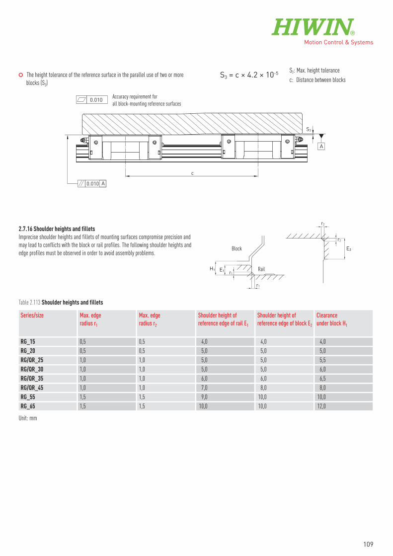
○�The height tolerance of the reference surface in the parallel use of two or more
blocks (S3)
S3: Max. height tolerance
c: Distance between blocksS3 = c × 4.2 × 10⁻⁵
c
S3
0.010
A
0.010 A
Accuracy requirement for
all block-mounting reference surfaces
2.7.16 Shoulder heights and fillets
Imprecise shoulder heights and fillets of mounting surfaces compromise precision and
may lead to conflicts with the block or rail profiles. The following shoulder heights and
edge profiles must be observed in order to avoid assembly problems.
H1 E1 r1
r1
r2
r2
Block
Rail
E2
Table 2.113 Shoulder heights and fillets
Series/size Max. edgeradius r1
Max. edgeradius r2
Shoulder height ofreference edge of rail E1
Shoulder height ofreference edge of block E2
Clearanceunder block H1
RG_15 0,5 0,5 4,0 4,0 4,0
RG_20 0,5 0,5 5,0 5,0 5,0
RG/QR_25 1,0 1,0 5,0 5,0 5,5
RG/QR_30 1,0 1,0 5,0 5,0 6,0
RG/QR_35 1,0 1,0 6,0 6,0 6,5
RG/QR_45 1,0 1,0 7,0 8,0 8,0
RG_55 1,5 1,5 9,0 10,0 10,0
RG_65 1,5 1,5 10,0 10,0 12,0
Unit: mm
109

2.8 Linear guideway, series PG
2.8.1 Properties of the linear guideways, series PG
The HIWIN linear guideways of the PG series are a special type of the HG/QH series
with the integrated, magnetic distance measuring system MAGIC. The distance
measuring systems of the MAGIC series are optimised for measuring the distances
travelled in linear movements and particularly on linear motor axes. The measuring
system consists of a magnetic measuring gauge on a stainless steel carrier tape and a
sensing unit. The robust housing with excellent electrical shielding and real-time
signal output make the HIWIN MAGIC series the distance measuring system of choice
for demanding applications.
In the PG series, the stylus is fitted directly on the HG/QH series block. The magnetic
tape is integrated in an additional groove in the HGR rail. The MAGIC distance
measuring system is also available as a model not dependent on the rail. The customer
can specify where the magnetic tape and stylus are positioned. For details, please refer
to the catalogue “Electric drive technology – linear motors, torque motors, positioning
measurement systems”.
2.8.2 Structure of the PG series
○�HG/QH series block
○�HG series rail with additional groove for measuring scale
○�Encoder can be fitted on HG-20, HG-25, QH-20 and QH-25 size blocks
○�Assembly direction: Looking towards the reference edge of the block, the encoder
is fitted on the left as standard. The encoder cable is also on the side of the
reference edge
2.8.3 Advantages
○�Zero contact measurement with 1 Vpp or digital output
○�Digital resolution of up to 0.5 μm
○�Encoder and housing are not sensitive to dust, humidity, oil and chips
○�Encoder with metal housing and IP67 protection mode
○�Simple assembly
○�Signal output in real time
○�Special housing for EMC optimization
Linear guidewaysPG series
110

2.8.4 Article numbers of the PG series
PG H W 20 C A 1 /2 T 1600 ZA H
PG series
H: based on HG seriesQ: based on QH series
Block type:W: flange blockH: high square blockL: low square block
Size: 20, 25 5)
Load type:C: heavy loadH: super heavy load
Block mounting:A: from aboveC: from above or below
Total number of blocks withsensors per axis set 6)
Blocks per axis set 6)
Rail mounting:R: from aboveT: from below (HGR20 only)
Rail length [mm]
Preload ID: Z0, ZA, ZB
Accuracy class: H
Continuation of article numbers of PG series
1 /2 KK E2 M A M 2500 L 1
Number of rails withmeasurement system
Rails per axis set 1)
Dust protection:SS, ZZ, DD, KK, SW, ZWX 2)
None: standardE2: with E2 oil lubrication unit
Measurementsystem type:M: MAGIC
Output signal:A: analogue 1 VppD: digital TTL
Index:M: multi index
Cable length [mm] 3)
Cable assembly:L: open end 3)
R: M17 round plug connector (male connector)S: sub-D connector for display PMED 4)
Encoder orientation 7):1: Orientation 1 (default)2: Orientation 23: Orientation 34: Orientation 4
Note:1) The figure 2 is also a quantity, i.e. one item of the above-mentioned article consists of a pair of rails. No number is specified for individual rails.2) If nothing is specified, the block is supplied with standard dust protection (standard end seal and bottom seal). For an overview of the various sealing systems, see page 20.3) With open ends, the 5000 cable length should be selected as standard.4) The display must be ordered separately.5) Not the same design as the HGR25R standard rail without groove. M5 assembly screw rather than M6.6) For the PG series, the total number of blocks per axis is specified (all blocks of the ordered article)7) See Chapter 2.8.8
111

2.8.5 Dimensions of the PG blocks
The following figure shows a HGH20CA/HGH25CA block. It is also possible to use the
modules with HG20, HG25, QH20 and QH25 block sizes. The overall dimensions then
change accordingly. The dimensions of all block sizes are shown in table 2.114.
L
B1
L1
B
H1H
Table 2.114 Dimensions of the block
Series/size L [mm] L1 [mm] B [mm] B1 [mm] H [mm] H1 [mm]HG_20C 118,0 41,5 44,0 43,0 30,0 4,6
HG_20H 132,7 41,5 44,0 43,0 30,0 4,6
HG_25C 124,5 41,5 48,0 46,4 40,0 5,5
HG_25H 145,1 41,5 48,0 46,4 40,0 5,5
QH_20C 117,2 41,5 44,0 43,0 30,0 4,6
QH_20H 131,9 41,5 44,0 43,0 30,0 4,6
QH_25C 123,9 41,5 48,0 46,4 40,0 5,5
QH_25H 144,5 41,5 48,0 46,4 40,0 5,5
2.8.6 Dimensions of the PG rails
WR
HR
Ød
ØD
h
P E2E1
L
Table 2.115 Dimensions of HGR_R G1
Series/size
Assembly screwfor rail [mm]
WR HR D h d P
Dimensions of rail [mm] Max. length[mm]
Max. lengthE1 = E2
E1/2 min[mm]
E1/2 max[mm]
Weight[kg/m]
HGR20R G1 M5 × 16 20,0 17,5 9,5 8,5 6,0 60,0 4000 3900 7 53 2,05
HGR25R G1C M5 × 20 23,0 22,0 9,5 8,5 6,0 60,0 2500 2500 7 53 3,05
Linear guidewaysPG series
112

h
S
HR
WR
P E2E1
L
Table 2.116 Dimensions of HGR_T G1
Series/size
WR HR S h P
Dimensions of rail [mm] Max. length[mm]
Max. lengthE1 = E2
E1/2 min[mm]
E1/2 max[mm]
Weight[kg/m]
HGR20T G1 20,0 17,5 M6 10,0 60,0 2500 2500 7 53 2,13
2.8.7 Tightening torques for mounting bolts
Insufficient tightening of the mounting bolts strongly compromises the precision of the
linear guideway; the following tightening torques are therefore recommended for the
relevant screw sizes.
Table 2.117 Tightening torques of the mounting bolts according to ISO 4762-12.9
HGR20R G1 M5 × 16 9
HGR20T G1 M6 13
Series/size Screw size Torque [Nm] Series/size Screw size Torque [Nm]HGR25R G1C M5 × 20 9
2.8.8 Orientation of the HIWIN MAGIC-PG encoder
According to the ordering code (Chapter 2.8.4) the HIWIN MAGIC-PG encoder is
available in four orientations as shown below. Without a statement about the required
orientation the encoder is delivered by default (orientation 1).
Orientation 1
Orientation 3
Positive countingdirection
Stop edge
Orientation 2
Orientation 4
113

2.8.9 Technical data for MAGIC positioning measurement system
Table 2.118 Electrical properties of MAGIC encoder
Type Analogue (1 Vpp) Digital (TTL)Output signal specification sin/cos 1 VPP (0,85 VPP – 1,2 VPP) Quadrature signal acc. to RS422
Resolution Infinite, signal period 1 mm 1 µm
Repetition accuracy bidirectional ± 0,003 mm ± 0,002 mm
Absolute accuracy ± 20 µm/m ± 20 µm/m
Reference signal 1) Periodic index impulse at a distance of 1 mm Periodic index impulse at a distance of 1 mm
Phase angle 90° ± 0,1° el 90°
DC component 2,5 V ± 0,3 V —
Distortion factor typ. < 0,1 % —
Operating voltage 5 V ± 5 % 5 V ± 5 %
Power consumption typ. 35 mA, max. 70 mA typ. 70 mA, max. 120 mA
Max. measurement speed 10 m/s 5 m/s
EMC class 3, according to IEC 801 3, according to IEC 801
1) Can be used with proximity switch
Table 2.119 Mechanical properties of MAGIC encoder
Type Analogue (1 Vpp) Digital (TTL)Housing material Aluminium alloy, encoder bottom made of stainless steel Aluminium alloy, encoder bottom made of stainless steel
Dimensions of MAGIC encoder L × B × H: 45 mm × 12 mm × 14 mm L × B × H: 45 mm × 12 mm × 14 mm
Standard cable length 2) 5000 mm 5000 mm
Min. bending radius cable 40 mm 40 mm
Protection class IP67 IP67
Operating temperature 0 °C to + 50 °C 0 °C to + 50 °C
Weight of MAGIC encoder 80 g 80 g
Weight of MAGIC-PG encoder 80 g 80 g
MAGIC-PG suitable for blocks HG-20, HG-25, QH-20, QH-25 HG-20, HG-25, QH-20, QH-25
2) For the use in drag chains we recommend our pre-assembled encoder cable with a pre-mounted round connector M17 (coupling, female) on one side, which matches the optional
round plug conector M17 (male) of the encoder. For details, please contact your HIWIN technician.
Linear guidewaysPG series
114

Table 2.120 Technical data of the magnetic scale
Ordering code(xxxx = length [mm])
8-08-0028-xxxx(incl. stainless steel protective cover tape)
Accuracy class 1) ± 20 µm/m
Linear expansion coefficient 11,5 × 10⁻⁶ m/K
Period 1 mm
Thickness magnetic scale 1,70 ± 0,10 mm
Thickness magnetic scale + protective cover tape 1,85 ± 0.15 mm
Width 10,05 ± 0,10 mm
Maximum length 24 m
Magnetic remanence > 240 mT
Pole pitch (distance north/south pole) 1 mm
Single reference marks optional
Material Elastomers, nitrile and EPDM
Temperature range 0 °C to +50 °C
Weight 70 g/m
1) At 20 °C
Fig. Seperate magnetic scale (left) without protective cover tape and integrated into
a profile rail (right) with stailess steel protective cover tape
115

2.8.10 Connection for MAGIC positioning measurement system
Cable assignment (analogue and digital variant) A high-quality, 8-core cable
(1 each of V1+, V1–, V2+, V2– and V0+, V0– (or A, Ā; B, B̄ and Z, Z̄ for the digital
variant) suitable for cable track is used twisted in pairs.
In drag lines, we generally recommend our pre-assembled extension cables, which
are designed especially for use in such lines. The extension cables are supplied with
a round plug connector on one end (female coupling) or customized.
2.8.11 MAGIC measuring system formats and outputs (analogue)
Signal format of sine/cosine 1 VPP output The electrical signals after the differential
input of the subsequent electronics. The HIWIN MAGIC sine/cosine 1 VPP interface is
cos = V1
sin = V2
V1–
V1+
V0–
V0+
V2–
V2+
GND
GND GND
GND
R3
R9
R11
R7
R5
R10
R6
U3
U2
R12
R8
Z2
R4
R13
R14
Z3+
5V4,
7k4,
7k
4
4
4
7
7
23
23
6
623
R2
7
U1 6R1Z1
120
120
120
V1
R
V2
Diagram on left:
Output signals within a benchmark period (1000 μm) in degrees (360° = 1000 μm).
Diagram on right:
Recommended subsequent electronics circuit for sine/cosine 1 VPP output
V1: V1 channel, V2: V2 channel, R: reference channel
strictly oriented towards the Siemens specification. The period length of the sine
output signal is 1 mm. The period length of the reference signal is 1 mm.
2.8.12 MAGIC measuring system formats and outputs (digital)
Digital TTL output The signals on A and B channels have a 90° phase shift (according
to RS422 specification in DIN 66259). Recommended terminal resistance Z = 120 Ω,
R
A B
A signal
B signal
Z signal (reference signal)
120 Ω
Z0
120 Ω
Z1
120 Ω
Z2
A
A B
B
Z
Z
GND
RS422
GND
RS422
GND
RS422
+5V +5V
+5V
Diagram on left:A: A signal, B: B signal, R: reference signal
Diagram on right:Recommended subsequent electronics circuit for TTL output
A: A channel, B: B channel, R: reference channel
output signals: A, Ā; B, B̄ und Z, Z̄, individual reference pulse (optional), defi-
nition of a minimum pulse duration possible as an option.
Linear guidewaysPG series
116

2.9 Accessories
2.9.1 Lubrication adapters
A grease nipple is attached to the front side of the block as standard (1). The
lubrication connection on the opposite side is sealed with a plug screw. Alternatively,
lubrication can also be carried out through one of the four laterally provided
connections on the recirculation unit (2) or from above (3). Grease nipples, lubrication
adapters or push-on connectors can be used for lubrication.
(1) Front side lubrication (2) Side lubrication (3) Lubrication from above
Table 2.121 Overview blocktype/thread size
Block type Thread sizefront/side
HG_15 M4
HG_20, HG_25, HG_30, HG_35 M6 × 0,75
HG_45, HG_55, HG_65 1/8 PT
QH_15 M4
QH_20, QH_25, QH_30, QH_35 M6 × 0,75
QH_45 1/8 PT
EG_15 M4
EG_20, EG_25, EG_30, EG_35 M6 × 0,75
QE_15 M4
QE_20, QE_25, QE_30, QE_35 M6 × 0,75
WE_17 M3
WE_21, WE_27, WE_35 M6 × 0,75
WE_50 1/8 PT
MG_15 M3
RG_15, RG_20 M4
RG_25, RG_30, RG_35 M6 × 0,75
RG_45, RG_55, RG_65 1/8 PT
QR_25, QR_30, QR_35 M6 × 0,75
QR_45 1/8 PT
117

○�Grease nipples M3 × 0,5P
Art.No.: 20-000275(standard)
Art.No.: 5-000061(option)
○�Grease nipples and lubrication fittings M4 × 0,7P
M6 × 0,75P
M4 × 0,7P
8
16,5
4
Ø5
107
LF-64 Art.No.: 20-000019
Art.No.: 20-000272(standard)
Art.No.: 20-000325(option)
The stated article numbers apply to the standard dust protection. Article numbers for optional dust protection available on request.
Linear guidewaysAccessories
118

○�Grease nipples and lubrication fittings M6 × 0,75P
M8 × 1,0P
M6 × 0,75P
10
19,5
3
Ø8
10
19,5
M8×1,0P 18
10M6×0,75P
3
Ø8
10
PT 1/8
M6 × 0,75P
12
23,5
Ø8
5
11
PT 1/8
M6×0,75PØ8
11
12
23,5
5
11
SF-76 Art.No.: 20-000006 LF-76 Art.No.: 20-000007 SF-86 Art.No.: 20-000008 LF-86 Art.No.: 20-000009
Art.No.: 20-000273(standard)
Art.No.: 20-000283(option)
Art.No.: 20-000290(option)
○�Grease nipples and lubrication fittings 1/8 PT
M8 × 1,0P
PT 1/8
10
20 2
Ø10
10
M8×1,0P
PT 1/8
18
10
202
Ø10
10
PT 1/8
PT 1/8
12
25 5
Ø11
12
PT 1/8
PT 1/8
12
25
Ø10
5
1212
SF-78 Art.No.: 20-000010 LF-78 Art.No.: 20-000011 SF-88 Art.No.: 20-000012 LF-88 Art.No.: 20-000013
Art.No.: 20-000280(standard)
Art.No.: 20-000292(option)
The stated article numbers apply to the standard dust protection. Article numbers for optional dust protection available on request.
119

Table 2.122 Push-in fittings
Steckverschraubung1 Steckverschraubung2
G
H
L
Ø D
G
H
L1
L2
Ø D
Straight push-in fitting 90° angled push-in fitting
M5
M6 × 0,75P
1018 2
Ø10
10 G 1/8
G 1/8
1223 3
Ø12
12Art.No.: 20-000416 – Adapter M5* Art.No.: 20-000418 – Adapter G 1/8*
* The adapters shown are needed for push-in fittings with threads M5 or G 1/8. Push-in fittings with thread M6 are screwed in the block without adapter.
Table 2.123 Dimensions of push-in fittings
Article number G Ø D Shape H L L1 L220-000439 M5 × 0,8 4 Straight 4 20,5 — —
20-000462 M5 × 0,8 6 Straight 4 22,5 — —
20-000465 M5 × 0,8 4 Angled 4 — 14,5 18,0
20-000466 M5 × 0,8 6 Angled 4 — 14,5 21,0
8-12-0127 M6 × 0,75 4 Straight 5 23,5 — —
20-000463 M6 × 0,75 6 Straight 4 22,5 — —
8-12-0128 M6 × 0,75 4 Angled 5 — 15,5 18,0
8-12-0138 M6 × 0,75 6 Angled 5 — 15,5 21,0
8-12-0131 G 1/8 4 Straight 6 20,0 — —
8-12-0136 G 1/8 6 Straight 6 24,0 — —
8-12-0130 G 1/8 4 Angled 6 — 20,0 20,0
8-12-0137 G 1/8 6 Angled 6 — 20,0 21,0
The stated article numbers apply to the standard dust protection. Article numbers for optional dust protection available on request.
Linear guidewaysAccessories
120

2.9.2 HIWIN grease guns and lubricants
Table 2.124 HIWIN grease guns
Article number Grease gun Lubrication adapter andset of nozzles
Direct filling Cartridge
20-000388 70 g
20-000332 70 g
20-000333 400 g
20-000358 —
Table 2.125 HIWIN greases
Grease type Area of application
70 g cartridge 400 g cartridge 1 kg container
Article number
G01 heavy-duty applications 20-000335 20-000336 20-000337
G02 Clean room applications 20-000338 20-000339 20-000340
G03 Clean room applications
High speed
20-000341 20-000342 20-000343
G04 High speed 20-000344 20-000345 20-000346
G05 Standard grease 20-000347 20-000348 20-000349
Table 2.126 HIWIN oils
Article number Description Scope of delivery Comment
20-000350 SHC 636 1-litre bottle Oil for filling the E2 lubrication tank
You will also find details about the HIWIN lubricants and lubrication of the linear
guideways in the “HIWIN assembly instructions for linear guideways” available
from www.hiwin.de.
121

Notes
122


Linear Actuators
Linear Motor Components
Linear Axes with Ballscrews
Ballscrews Linear Motor Systems
Rotary Tables
Ball Bearings
Linear Guideways
Drives
GermanyHIWIN GmbHBrücklesbünd 2D-77654 OffenburgPhone +49 (0) 7 81 9 32 78 - 0Fax +49 (0) 7 81 9 32 78 - [email protected]
TaiwanHeadquartersHIWIN Technologies Corp.No. 7, Jingke RoadNantun District Taichung Precision Machinery ParkTaichung 40852, TaiwanPhone +886-4-2359-4510Fax [email protected]
TaiwanHeadquartersHIWIN Mikrosystem Corp.No. 6, Jingke Central RoadNantun District Taichung Precision Machinery ParkTaichung 40852, TaiwanPhone +886-4-2355-0110Fax [email protected]
ItalyHIWIN SrlVia Pitagora 4I-20861 Brugherio (MB)Phone +39 039 287 61 68Fax +39 039 287 43 [email protected]
PolandHIWIN GmbHul. Puławska 405a PL-02-801 WarszawaPhone +48 22 544 07 07Fax +48 22 544 07 [email protected]
CzechiaHIWIN s.r.o.Medkova 888/11CZ-62700 BRNOPhone +42 05 48 528 238Fax +42 05 48 220 [email protected]
SlovakiaHIWIN s.r.o., o.z.z.o.Mládežnicka 2101SK-01701 Považská BystricaPhone +421 424 43 47 77Fax +421 424 26 23 [email protected]
SwitzerlandHIWIN Schweiz GmbHEichwiesstrasse 20CH-8645 JonaPhone +41 (0) 55 225 00 25Fax +41 (0) 55 225 00 [email protected]
France HIWIN France s.a.r.l.20 Rue du Vieux BourgF-61370 EchauffourPhone +33 (2) 33 34 11 15Fax +33 (2) 33 34 73 [email protected]
AustriaHIWIN [email protected]
HungaryHIWIN [email protected]
NetherlandsHIWIN [email protected]
JapanHIWIN [email protected]
USAHIWIN [email protected]
ChinaHIWIN Corp.www.hiwin.cn
KoreaHIWIN Corp.www.hiwin.kr
SingaporeHIWIN Corp.www.hiwin.sg
GW-09-6-EN-1510-K