lining the hats sewage tunnel with high-performance concrete · pdf file ·...
TRANSCRIPT

© 2
015
All R
ight
s R
eser
ved
Gammon Construction Ltd. (Ir. Dr. Herbert Zheng, Ir. Martin Ho)
AECOM Asia Co. Ltd (Ir. Benny Chan)
Drainage Services Department, the Government of the Hong Kong Special
Administration Region (Ir. P. F. Ma)
SCCT Annual Concrete Seminar 2015 Youth Square, Chai Wan, 29 April 2015
Lining the HATS Sewage Tunnel with High-performance Concrete in Hong Kong
1

© 2
015
All R
ight
s R
eser
ved
“Failure is success in progress.”
On 20 March, 2014
2

© 2
015
All R
ight
s R
eser
ved
“There is always a gift in any challenge.”
On 28 March, 2014
3
© 2
015
All R
ight
s R
eser
ved
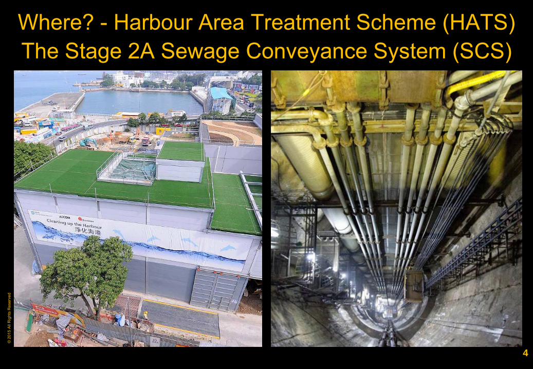
Where? - Harbour Area Treatment Scheme (HATS) The Stage 2A Sewage Conveyance System (SCS)
4

© 2
015
All R
ight
s R
eser
ved
Contents
A. HATS Stage 2A Sewage Conveyance System
B. Mix characterization and risk prevention framework
C. Long time transportation and crack control
D. High-performance concretes at HATS
E. Conclusions
5

© 2
015
All R
ight
s R
eser
ved
A HATS Stage 2A
Sewage Conveyance System
6

© 2
015
All R
ight
s R
eser
ved
HATS Stage 2A SCS alignment
Central Wan Chai East
North Point
Sandy Bay
Cyberport
Wah Fu
Aberdeen
Ap Lei Chau
Sai Ying Pun
Stage 1 (by others – completed)
Stage 2A Sewage Conveyance System
Stonecutters Island
Kowloon
Hong Kong Island
J K
L
M
N
P
Q 7

© 2
015
All R
ight
s R
eser
ved
200K m3 marine
concrete A total of 21km deep tunnels with depth varying up to 160m below sea level, and unreinforced concrete lining diameters ranging from 900mm to 3,050mm.
Contract No. DC/2007/23 (Total tunnel length: 12.05km)
Contract No. DC/2007/24
Contract No. DC/2008/09
Tunnel J (3.2km)
Tunnel K (4.3km)
Tunnel L (4.55km)
200,000 m3 marine concrete
8

© 2
015
All R
ight
s R
eser
ved
Quality assurance and the Swiss Cheese
Modified from J Reason, “Managing the risks of organizational accidents” , NASA Annual Risk Management Conference 2004, Cleveland, US, 26-29 Oct. 2004
Some viable solutions due to proper actions
Other viable solutions due to beneficial latent conditions
Challenges in successive layers
Inputs
Targets
9

© 2
015
All R
ight
s R
eser
ved
B Mix Characterization and
Risk Prevention Framework
10

© 2
015
All R
ight
s R
eser
ved
Prescribed requirements for structural design Category
GS (2006) Sections 16 & 21 - Marine Concrete (Grade 45/20D)
DSD HATS (Plain marine concrete Grade 45/20D)
A Concrete mix (1) Min grade: 45 MPa (2) Max 0.38 w/cm ratio (3) Mix design: from 375 to 450 kg/m3 cementitious materials (cm), with 25-40%
PFA with 5-10% condensed silica fume PC, SRPC, PFAC, PBFC, GGBS, CSF
SRPC (Sulphate resisting Portland cement) or equivalent
B Concrete Performance
Temperature Placing temperature < 30 OC (1) Placing temperature < 32 OC (2) Peak ≤ 70 OC (3) Max difference ≤ 20 OC
Strength Same as normal concrete Extra requirements on any consecutive 40 results of 28-day cube strength: Coefficient of variation ≤ 8% Average strength ≥ Grade strength + 2 x
Standard Deviation Durability Not specified 28-day AASHTO chloride diffusion (6 hour test)
≤ 1,000 coulombs 28-day Water sorptivity ≤ 0.07 mm/min0.5
11

© 2
015
All R
ight
s R
eser
ved
Logistic requirements
200,000m3 Grade 45 and 60 unreinforced high performance concrete, up to Grade 80
Typical 300m3 (max. 370m3) single pour volume (max. length = 22.5m for Tunnel K, 60m for Tunnel L)
12
© 2
015
All R
ight
s R
eser
ved
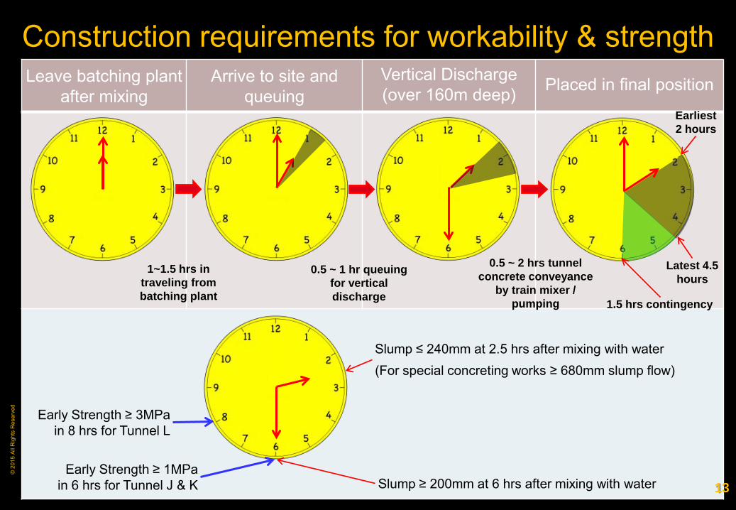
Leave batching plant after mixing
Arrive to site and queuing
Vertical Discharge (over 160m deep) Placed in final position
Construction requirements for workability & strength
1~1.5 hrs in traveling from batching plant
0.5 ~ 1 hr queuing for vertical discharge
0.5 ~ 2 hrs tunnel concrete conveyance
by train mixer / pumping 1.5 hrs contingency
Earliest 2 hours
Latest 4.5 hours
Slump ≤ 240mm at 2.5 hrs after mixing with water (For special concreting works ≥ 680mm slump flow)
Slump ≥ 200mm at 6 hrs after mixing with water
Early Strength ≥ 3MPa in 8 hrs for Tunnel L
Early Strength ≥ 1MPa in 6 hrs for Tunnel J & K 13

© 2
015
All R
ight
s R
eser
ved
High-performance concrete (HPC)
“Concrete meeting special combinations of performance
and uniformity requirements that cannot always be achieved
routinely using conventional constituents and normal mixing,
placing, and curing practices.”
- American Concrete Institute, January 2013
14

© 2
015
All R
ight
s R
eser
ved
Conclusions at SCCT
Annual Concrete Seminar 2007
15
© 2
015
All R
ight
s R
eser
ved
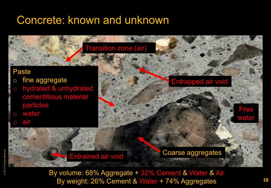
Concrete: known and unknown
Transition zone (air)
Entrapped air void
Entrained air void Coarse aggregates
Paste o fine aggregate o hydrated & unhydrated
cementitious material particles
o water o air
Free water
By volume: 68% Aggregate + 32% Cement & Water & Air By weight: 26% Cement & Water + 74% Aggregates 16

© 2
015
All R
ight
s R
eser
ved
Concrete properties: time-dependent
Workability / consistency
Volume change:
Temperature rise
Shrinkage
Resistance to environmental loadings
Mechanical properties: strengths and modulus
Durability: absorption, permeability and abrasion resistance
Others: ductility and fire resistance
17

© 2
015
All R
ight
s R
eser
ved
Mix design and optimal packing
At optimal state: denser micro structure higher workability
Normal concrete High-performance concrete
18
less segregation higher density higher strength
© 2
015
All R
ight
s R
eser
ved
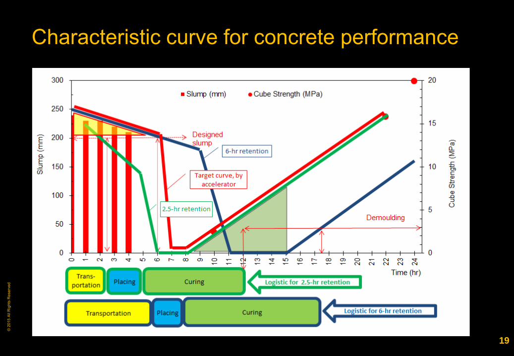
Characteristic curve for concrete performance
19

© 2
015
All R
ight
s R
eser
ved
Framework of quality management
20

© 2
015
All R
ight
s R
eser
ved
C Long Time Transportation and
Crack Control
21
© 2
015
All R
ight
s R
eser
ved
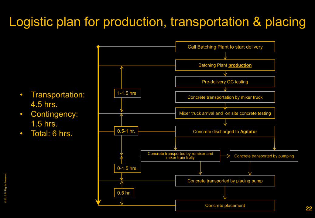
Logistic plan for production, transportation & placing
Call Batching Plant to start delivery
Batching Plant production
Mixer truck arrival and on site concrete testing
Concrete discharged to Agitator
Concrete transported by remixer and mixer train trolly Concrete transported by pumping
Concrete transported by placing pump
Concrete placement
Pre-delivery QC testing
Concrete transportation by mixer truck 1-1.5 hrs.
0-1.5 hrs.
0.5-1 hr.
0.5 hr.
• Transportation: 4.5 hrs.
• Contingency: 1.5 hrs.
• Total: 6 hrs.
22

© 2
015
All R
ight
s R
eser
ved
Long distance pumping & train mixer
Max 1.2km single pumping
Train mixer
Concrete discharged from train mixer to pump receiving hopper
23

© 2
015
All R
ight
s R
eser
ved
Advantages of long-distance pumping
Rapid transportation and placement of concrete at a rate of
more than 35m3/hour/pump
Perform concreting where traffic condition is restricted, or
access is difficult such as in underground construction
Maintain concrete supply in line with concrete placement
rate to enhance concrete crews’ efficiency
24

© 2
015
All R
ight
s R
eser
ved
Common problems encounted in long distance pumping Loss of workability and temperature control
Insufficient headroom for pump of proper capacity
Pump or pump line blockage
Mix design deficiencies
Pipeline and joint deficiencies
Operating error
Slow reaction in locating and cleaning pipe blockage
Lack of contingency plan
Insufficient risk prevention measures in place
25

© 2
015
All R
ight
s R
eser
ved
Unexpected loss of workability
Concrete tested after pumping does not achieve deigned performance criteria
Pump pipe line blocked during pumping, causing delays in concrete construction
26

© 2
015
All R
ight
s R
eser
ved
Pumpline blockages C
ause
s of
pum
ping
sys
tem
bl
ocka
ge
Mix design deficiencies
Pipeline and joint deficiencies
Failure to response properly
Organizational accident
27
© 2
015
All R
ight
s R
eser
ved
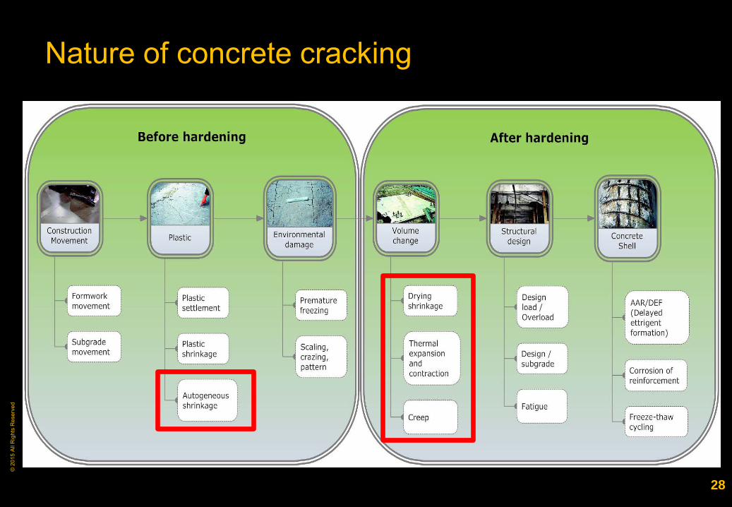
Nature of concrete cracking
28

© 2
015
All R
ight
s R
eser
ved
Early-age dimension stability
Dim
ensi
on s
tabi
lity
Thermal movement
Shrinkage
Creep
Expansion
Dimension stability (or volume change): an increase or decrease in volume due to any cause.
29

© 2
015
All R
ight
s R
eser
ved
Thermal expansion and contraction
Factors affecting concrete thermal movement: Cement hydration Ambient temperature Sunlight & wind exposure Heat dissipation
Before harden-ing
After hardening
Inactive
Rat
e of
hea
t evo
lutio
n
Time Process of cement hydration
Temperature & stress vs time “In Search of Crack-Free Concrete”, David A. Lange, 2005 30
© 2
015
All R
ight
s R
eser
ved
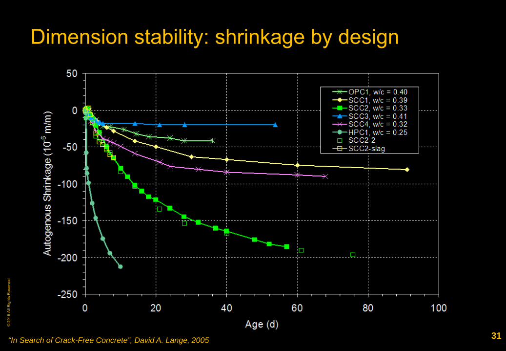
Dimension stability: shrinkage by design
“In Search of Crack-Free Concrete”, David A. Lange, 2005 31
© 2
015
All R
ight
s R
eser
ved
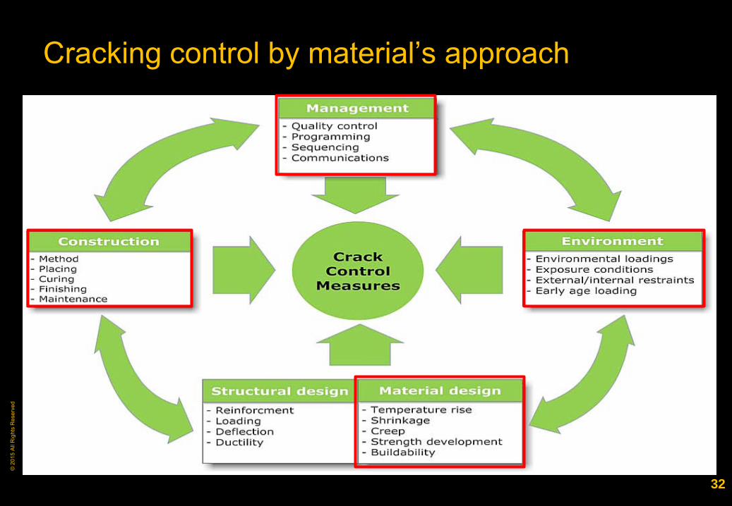
Cracking control by material’s approach
32

© 2
015
All R
ight
s R
eser
ved
D High-performance Concretes at HATS
33

© 2
015
All R
ight
s R
eser
ved
List of concrete mixes
Mix ID Mix Type Desig-
nation Workability cm (kg/m3)
PFA Content
CSF Content w/cm
Coarse Agg.
(kg/m3)
Fine Agg.
(kg/m3)
Admix-tures (L/m3)
1 Self-compacting
15/10D 680mm SF 440 58% 0% 0.42 830 820 6
2 45/10D 700mm SF 435 31% 6% 0.37 950 780 8 3
High-performance
45/20D
200mm slump
435 31% 6% 0.38 1000 730 11 4 45/20D 435 31% 6% 0.37 1000 750 11 5 60/20D 450 30% 6% 0.35 1000 765 8 6 60/20D 450 30% 6% 0.35 1000 765 8 7 80/20D 450 25% 5% 0.31 1020 770 11 8 Very early
strength 45/20D 225mm
slump 435 31% 6% 0.38 950 780 17
9 60/20D 450 28% 6% 0.34 940 810 17 Remarks: 1. cm – Cementitious materials; PFA – Pulverized fly ash; CSF – Condensed silica fume; w/cm – Water
to cementitious materials ratio; SF – Slump flow. 2. Mix 1 is used for backfilling at Sai Ying Pun Junction Shaft. Mix 2 is used for Stonecutter adit. 3. Mix 3-7 is used for tunnel lining, while mix 8 and 9 are prepared for contingency use.
34

© 2
015
All R
ight
s R
eser
ved
Portion of Stage 2A SCS tunnel and shaft network
Mix 5, 6,7 Tunnel J & K (7.5km)
Mix 2, 3, 4
Tunnel L (4.55km)
Mix 1
Sai Yin Pun Junction Shaft
35

© 2
015
All R
ight
s R
eser
ved
Placing of lining concrete at Tunnel J, K (Invert)
36

© 2
015
All R
ight
s R
eser
ved
Placing of lining concrete at Tunnel J, K (Crown)
37
© 2
015
All R
ight
s R
eser
ved
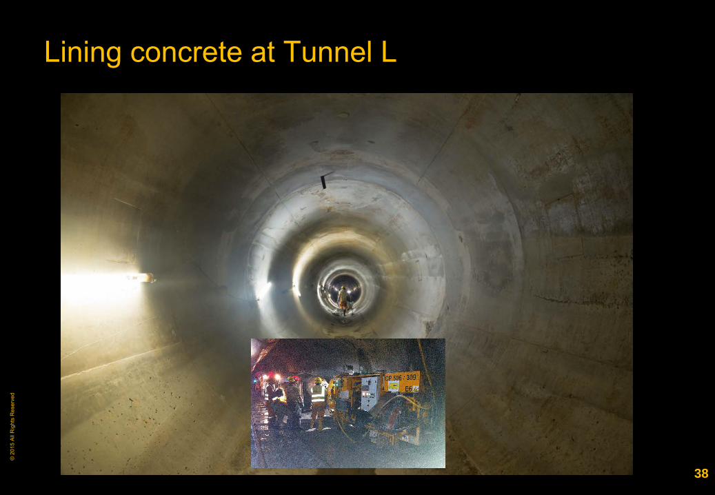
Lining concrete at Tunnel L
38

© 2
015
All R
ight
s R
eser
ved
In-situ trial of low strength self-compacting concrete
39

© 2
015
All R
ight
s R
eser
ved
E Conclusions
40

© 2
015
All R
ight
s R
eser
ved
41

© 2
015
All R
ight
s R
eser
ved
Conclusions
1. Various high-performance concretes have brought substantial benefits to HATS Stage 2A Sewage Conveyance System project by proper planning and implementation of:
Risk prevention based quality management strategy;
Technological advancement in design, production, supply and application of HPC.
2. High-performance concrete has significantly facilitated the design and construction of HATS Stage 2A Sewage tunnel lining in aspects of buildability, construction programme and durability.
3. Project applications also show that the potentials of HPC durability, i.e. acid resistance, can be enhanced so that longer design life of sewage concrete structures can be achieved.
42

© 2
015
All R
ight
s R
eser
ved
Thank You
43
Lei Yue Mun
Quarry Bay
Tsim Sha Tsui
Central
Route of harbour race in 1906 ~ 1978
Route of harbour race since 2011