linx 7-5 user's · pdf filelinx7-5 terminal hardware synopsis ... linx 7-5 user's...
TRANSCRIPT
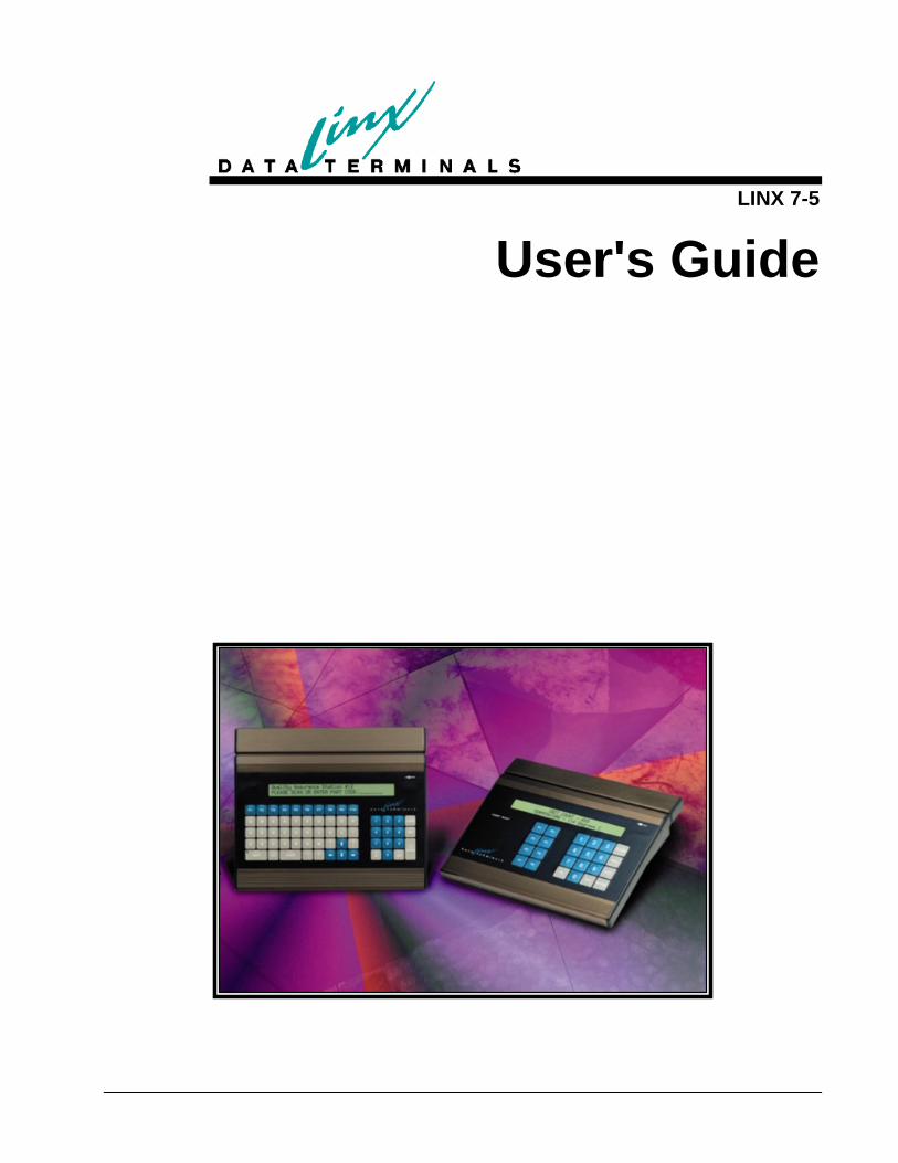
LINX 7-5
User's Guide

March 12, 2007 Copyright LINX Data Terminals, Inc.
All Rights Reserved

Contents
Preface 1 Introduction to the Linx7-5 Terminal ........................................................................................1 Overall Description....................................................................................................................2
Product Perspective .....................................................................................................2 Product Functions........................................................................................................2 User Characteristics.....................................................................................................2 Constraints...................................................................................................................2 Requirements Subsets..................................................................................................2
Using the Linx 7-5 Data Collection Terminal ...........................................................................4 From the Complex to the Simple.................................................................................4
Linx7-5 Terminal Hardware Synopsis.......................................................................................7 Linx7-5 Block Diagram.............................................................................................................8 Powering the Linx7-5 terminal ..................................................................................................9 The Linx 7-5 Terminal Normal boot sequence........................................................................11
Linx7-5 Terminal Status Displays 14 Format for the Terminal Status display ...................................................................................14 Detailed Status Display FIELD Descriptions ..........................................................................15
Line #1 FIELD: .........................................................................................................15 Line #2 FIELD: .........................................................................................................15
Configuration Status Display...................................................................................................16 Time Display ...........................................................................................................................16
Linx7-5 Menu System 17 Overview of Menu System ......................................................................................................17 Using Menus from the Keypad................................................................................................17
Selecting a Menu .......................................................................................................17 Entering a Sub-menu .................................................................................................18 Examining & Selecting Parameters ...........................................................................18 Changing Parameters.................................................................................................18 Exiting Sub-menus ....................................................................................................18 Exiting Main Menu ...................................................................................................19 Diagnostics Menu......................................................................................................19
Linx7-5 Menu Descriptions .....................................................................................................19 Terminal Menu ..........................................................................................................19 Network Menu...........................................................................................................20 Diagnostics Menu......................................................................................................21 Information Menu......................................................................................................22
Linx7-5 User Diagnostics 23 Keypad/Barcode/MSR Test .....................................................................................................23 Display Test .............................................................................................................................23 Destructive DRAM Test ..........................................................................................................23
LINX 7-5 User's Guide Contents • iii

Destructive SRAM Test...........................................................................................................23 Time Display ...........................................................................................................................24 LED Lamp Test .......................................................................................................................24 COM Loopback Test ...............................................................................................................24 COM Transmit Test .................................................................................................................24 COM Receive Test ..................................................................................................................24 Sense Lines Test ......................................................................................................................25 Control Lines Test ...................................................................................................................25 Vsmart FIU Test ......................................................................................................................25 Ethernet Internal Lpbk.............................................................................................................25 Ethernet Host Ping Test ...........................................................................................................25 Reset PowerUP ........................................................................................................................25 Reset to Defaults......................................................................................................................25
Linx7-5 Web Server 26 Web Server Overview..............................................................................................................26
Information and Statistics..........................................................................................27 Setup and Configuration............................................................................................29 Maintenance and Control ..........................................................................................35
Installing Peripherals 38 Back Plate connectors..............................................................................................................38
Appendixes 41 Appendix A..............................................................................................................................41
10/100 Mb Ethernet Installation Guidelines..............................................................41 Appendix B..............................................................................................................................42
Updating Code Blocks In Flash.................................................................................42 Updating FLASH via Ethernet: .................................................................................42 Updating FLASH via COM1 Port: ............................................................................43
Appendix C..............................................................................................................................44 Using FTP.EXE - Windows Command Line FTP Client with the Linx7-5 ..............44 COMMON FTP OPERATIONS...............................................................................45 TABLE 1 ...................................................................................................................46
Appendix D..............................................................................................................................47 LINX 7-5 MEMORY MAP.......................................................................................47
Appendix E ..............................................................................................................................48 Setup of the Bioscrypt V-Smart reader on the Linx7-5 Terminal..............................48
APPENDIX F ..........................................................................................................................50 Cabling requirements to use the V-Smart with the Linx7-5 ......................................50
Appendix G..............................................................................................................................53 Using the VT100 Terminal Emulation on the Linx7-5..............................................53 VT100 Support: .........................................................................................................53 SAMPLE TC.CFG FILE (as supplied by LINX) ......................................................55
iv • Contents LINX 7-5 User's Guide

Preface
Introduction to the Linx7-5 Terminal The LINX upgrade to the existing LINX5, (hereafter known as the Linx7-5), will provide a terminal platform upgrade path for the existing LINX5 users. Since this terminal will use standard TCP, FTP, and HTTP protocols to communicate with the host, the Linx7-5 will NOT support any connectivity to the existing LINX5 terminals.
The Linx7-5 software discussed within this document refers to firmware that exists within the terminal only.
LINX 7-5 User's Guide Preface • 1

Overall Description
Product Perspective The Linx7-5 comprises of a new state-of-art motherboard installed in the current LINX5 chassis and using the current I/O board hardware. Consequently, the Linx7-5 can be a cost effective alternative to buying completely new hardware to upgrade a network. It will be offered as a complete terminal and as an “upgrade kit” for current LINX5 users. It will interface to all existing I/O as well as add the capability for 100mb Ethernet connectivity. It will be functionally similar to the current LINX5, so employees should be not affected by the upgrade. Of course from a programming / configuration / maintenance standpoint, the Linx7-5 will be a different animal entirely from its predecessor. It will provide a more modern, non-proprietary development environment, “easy” configuration and management, and Ethernet connectivity.
Product Functions The Linx7-5 will provide the functional equivalence of the current LINX5 and much more. For instance, it will provide for: a means of remote management and diagnostics, standard TCP communications, and the capability to run an application in many different operating modes. These modes are explained in greater detail under the “Using the LINX 7-5 Data Collection Terminal” Section.
User Characteristics Because the Linx7-5 is a functional equivalent of its predecessor, the user or operator characteristics will remain unchanged.
Constraints The major design constraint for the first release of the Linx7-5 will be backward compatibility with the current LINX5 IO board and chassis.
Requirements Subsets Functional Equivalence of Existing LINX5s
• LINX5 I/O Board hardware/software connectivity
• Magnetic Stripe Track 1 and 2 support (exclusive)
• Standard Bar Code support
• LINX5 Keyboard support (QWERTY and 24-Key only)
• LINX5 Keyboard LED support
• LINX5 LCD Display support (2x40 only)
• Real Time Clock
• Audio Alarm (with both frequency and duration)
2 • Preface LINX 7-5 User's Guide

Means of Remote Management and Diagnostics • Supports ICMP for the purpose of verifying connectivity.
• Uses dynamic and statically assigned IP addresses.
• Allows remote configuration via a web browser.
• Supports standard FTP file transfers.
• Supports a version query.
• Supports serial number query/set commands
• Supports time query/set commands.
• Supports application information query
• Local hardware diagnostics / statistics
Standard TCP Communications
• The Linx7-5 will use a standard TCP connection between the host and the terminal.
LINX 7-5 User's Guide Preface • 3

Using the Linx 7-5 Data Collection Terminal The Linx 7-5 Data Collection Terminal is a programmable device, which gives it the ability to adapt to a rather wide variety of uses. But since not all uses require sophisticated (and complex) programming methods, Linx provides a variety of ways to control the DCT, ranging from complex methods that grant complete control but require considerable programming training, to much simpler methods that do not offer as much functionality (although still quite a bit) but require little or no such training.
Linx provides a few small demo programs for all the methods that are discussed. We can also develop custom applications.
From the Complex to the Simple Native Mode The most feature rich method of programming the Linx 7-5 DCT is what we call “native mode”. This is the most complex and expensive, but allows access to all of the terminal’s capabilities at high speed. There are comparatively few applications, such as high speed process control, where this mode will be required. The vast majority of applications can comfortably use one of the simpler modes. Native mode is about what you might expect: it is essentially “C” programming using a cross-compiler to prepare programs that run directly under the control of the terminal’s operating system. In native mode, the terminal can operate autonomously, or it can operate as a component in a network (including under the control of another computer); the choice is up to you.
The Linx7-5 can also support a single user defined task (application). This application must be created by the user or VAR, using a Motorola Coldfire ‘C’ compiler. Currently, the Crossware Compiler is the only one supported. However, others will be validated in the future. LINX provides a "hook" for the user task through ThreadX the real time operating system being utilized. Although LINX has acquired source code and licenses for the stack, RTOS, and the compiler, the user and/or VAR will only require a user license for the compiler.
LINX will provide a set of libraries for special I/O devices access.
File access will occur through ‘C” API functions.
TCP/IP stack socket function access will be included.
Host Control Mode Almost as feature rich as native mode is “HCL mode”. The major difference is that the controlling program runs on a host computer rather than on the terminal itself. Due to the delays that are associated with communications, this will almost always preclude real-time applications, but otherwise grants a very high degree of control over the terminal. The major drawback of Host Control Mode is that the terminal is not autonomous; if the host becomes unavailable, the terminal becomes non-functional. Like Native mode, experience at programming should be considered required.
For the Windows host environment, Linx supplies several .NET based components that allow rapid development of host applications. Sorry, no such tools currently exist for non-Windows environments, but we do supply the necessary reference
4 • Preface LINX 7-5 User's Guide

materials. For an easier method of implementation, see the next mode: the Linx Automator.
Linx Automator Mode
Note: Automator requires .NET 1.1 or higher.
LINX Automator is a .NET class library intended to allow the development of Windows based applications that can control one or more LINX VII-5 Data Collection Terminals. Although it bears a slight relationship to LinxScript, there is one huge difference: LINX Automator runs on a host, whereas LinxScript runs on the terminal.
LINX Automator is a companion to LINX HCL.NET, which is also a Windows based class library that can be used to control terminals. Either can be used to develop host based terminal control applications, but they are significantly different in underlying philosophy. HCL.NET can be thought of as the counterpart to “native mode” programming on the terminals, whereas LINX Automator can be thought of as the counterpart to LinxScript. HCL.NET grants more complete control of the terminal, but at the cost of greater complexity. Automator is simpler, but does not offer the fine detail of control. For the majority of applications, we anticipate the Automator will be the methodology of choice. Users needing to exercise the greater degree of control offered by HCL.NET should be prepared for a lengthier and more complex development cycle.
Since Automator is a .NET class library, at least some knowledge of working with .NET is considered required. The user application can be written in either VB.NET, C#, or Managed C++. The demonstration application, a rather minimal one, is written in C#. It might be possible to develop applications in ASP.NET, but this was not a design criteria and no attempt to test the feasability of this approach has been made.
Scripted Mode This is the middle of the road; our own fairly simple programming language, LinxScript, that runs right on the terminal. LinxScript offers nearly complete control of the terminal but without the complexities of either native or host controlled modes.
No particular type of host or other specialized tools are required; all you need is an FTP client and a text editor. Programming experience is helpful but not required; experienced programmers can usually start developing LinxScript almost right out of the box, and even non-programmers can usually develop and deploy modest applications in a fairly short time.
When using LinxScript, the terminal is typically autonomous; no host connection is required, although it is allowed. Data collected by the terminal can be retrieved either via FTP, or via our “HostQueue” mechanism. The latter is our own protocol that allows data to be collected from the terminal very quickly (usually almost real-time) while still allowing the terminal to operate (and data to be preserved) when the host is not available. Linx supplies a Windows based application, “Evolution”, that can manage a network of such terminals. For the non-Windows environment, the appropriate reference material is available. HostQueue is a subset of the Host Control Mode mentioned earlier, but does not require a constant connection between the host and the terminal.
LinxScript does offer a limited ability for the application to perform arithmetic and to control “files” residing on the terminal. LinxScript also provides a limited ability to operate in a cooperative manner with other computers. This ability is currently only provided via the terminal’s serial ports, but Telnet capability is currently being developed and other mechanisms may be available in the future. LinxScript can also
LINX 7-5 User's Guide Preface • 5

perform local validation of input; that is, the program can determine if the badge just swiped is valid (this does require that a list of valid badges be downloaded from the host, which can be done via FTP).
LinxScript is suitable for more complex Time & Attendance applications, and some even more complex, that require some degree of local processing of the data (other than simple validation or formatting). Furthermore, LinxScript can also provide transaction based Terminal to host communications where the terminal sends queries and the Host responds accordingly. For instance, this can be used for Host-based lookups of employee information that is sent back to the terminal. Of course, any Host lookups must be done using a specially created Host application or by using the Linx Evolution software
SPI The Simplified Programming Interface might be considered LinxScript, Junior. It is specifically intended to be usable by non-programmers (although programming experience is useful) while still offering a fairly high degree of control. A SPI “program” is simply a set of rules, each of which describes what the terminal should display at that time, and what sort of input it should accept from the user. Based on that input, a new rule will be selected. When all the information that is desired has been collected, it will be sent. SPI allows the same data delivery options that LinxScript offers.
Like LinxScript, SPI requires only the most basic of tools (a text editor and an FTP client) to prepare and install programs. It also provides the local data validation ability. Unlike LinxScript, SPI does not provide arithmetic, file control, or the limited transactional ability.
SPI is suitable for the majority of Time & Attendance applications, those that do not require local processing (other than formatting) of the collected data.
ITAS “Integrated Time and Attendance” is the most basic mode. It does not require any programming at all, being entirely table driven. ITAS “programs” can manage simple Time & Attendance applications, including local data validation, but offers very few options regarding the number of displays that can be presented to the user. However, for the basic “Swipe & Go” or other such simple applications, an ITAS “program” can usually be prepared in just a few minutes even by non-programmers (this assumes a Windows based host). ITAS also offers both the FTP and HostQueue data delivery mechanisms available to the other modes.
Linx provides a Windows based “Wizard” that can prepare ITAS configuration files. These files can also be edited via any suitable editor on non-Windows platforms.
VT100 TELNET Terminal Emulation This is (currently) the final mode of operation for the Linx 7-5 terminal. Since the VT100 Terminal Emulation mode is available to any Host that has a Telnet Server, this mode may be the easiest mode to implement, especially if you are already using Terminal emulation. In this mode, the terminal acts and appears as a VT100 Terminal. The operation and setup of this mode are detailed in Appendix G.
6 • Preface LINX 7-5 User's Guide

Linx7-5 Terminal Hardware Synopsis The Linx7-5 is an upgrade to the present LINX5 terminal and will provide 10/100MB Ethernet connectivity. This upgrade terminal incorporates a TCP/IP stack and allows file downloads via FTP.
The main hardware functions include: • Processor: Motorola Coldfire MCF5272 @ 66Mhz
• Main Memory: 16MB SDRAM
• Non-Volatile Memory: .5MB Battery-backed SRAM
• Non-Volatile Program Storage: 2MB Flash
• Real-time clock to provide non-volatile time and date information.
• Serial interface to provide interoperability with the present LINX5 I/O board.
• 3 OPTO-Isolated Digital input lines
• 1 Relay control line
• 3 TTL Digital output lines
• A Mylar Speaker for audio tone generation.
• 2 “Full” RS232 serial ports
• 10/100MB Ethernet interface for high-speed network communication.
LINX 7-5 User's Guide Preface • 7

Linx7-5 Block Diagram
8 • Preface LINX 7-5 User's Guide

Powering the Linx7-5 terminal The Linx7-5 has 4 major code blocks in flash memory. In order, these are:
Boot block: This block contains most of the hardware low-level initialization code, boot diagnostics tests and the RS232 flash block update code.
Main block: This block contains more hardware initialization code and the hardware access functions.
OS block: This is the largest and most important code block which includes the following:
RTOS (Real Time Operating System)
TCP/IP stack (including the Web server and the FTP server)
Status displays
Menu system
API functions for the User ‘C’ application
HCL executor responds to HCL commands from the Host in HCL application mode.
LINX T&A Application task executes as defined in the configuration file.
Application block; This block contains the user ‘C’ application code if this operating mode is selected.
If this message does not disappear, the terminal is NOT functioning properly!
When the terminal is first powered on the LCD display will show an initialization string from the I/O board. If the I/O board powers on successfully, the following message will be displayed for a very short time:
8xC52 OK-V8.1 -displayed by LINX Terminal
Once, the I/O message disappears, the firmware in the Linx7-5 determines if the low-level 'BOOT' diagnostics have been executed. If this is the very first power-on, (usually at the factory), or if the menu option: "Destructive SRAM Test" was selected, the firmware will exercise a series of 'BOOT' diagnostics to ensure that the hardware is functional.
These diagnostics include the following tests: • I/O Echo Test This test will execute the "ECHO" command to the I/O board. The test will echo bytes 00,11,22,33...FF to verify that the I/O interface is operating correctly.
• RTC Test This test will verify that the RTC can be accessed. RTC Address 55(hex) and 2A(hex) will be read/write verified with data patterns off 55(hex) and AA(hex). Minimal resources will be used. (Since the SDRAM has not been verified yet!)
LINX 7-5 User's Guide Preface • 9

• Synchronous DRAM Tests SDRAM Test #1;
This test will destructively test the SDRAM. The following data patterns will be used to verify memory integrity:
DATA: $55555555, $AAAAAAAA, $00000000
SDRAM Test #2;
This test will destructively test the SDRAM by initializing all unique addresses with data to verify the integrity of the SDRAM address lines.
• Battery-Backed SRAM Tests SRAM Test #1;
This test will destructively test the SRAM. The following data patterns will be used to verify memory integrity:
DATA: $55555555, $AAAAAAAA, $00000000
SRAM Test #2;
This test will destructively test the SRAM by initializing all unique addresses with data to verify the integrity of the SRAM address lines.
• COM1 External Loopback Test This test will detect if a “Loopback” plug has been installed. If it is found, then data 00-FF will be transmitted and then received to verify that UART port #1 is operational.
• COM2 External Loopback Test This test will detect if a “Loopback” plug has been installed. If it is found, then data 00-FF will be transmitted and then received to verify that UART port #2 is operational.
• Ethernet Internal Loopback Test This routine will verify that the Ethernet circuitry is operational. This will test the Coldfire Ethernet MAC and the Level-One (Intel) 10/100mb Physical Interface by executing an internal TX/RX loopback via the Intel LXT972A Physical Interface.
• Keyboard LED test This test will cycle through all of the keyboard LEDs. First turning all “ON”, then all “OFF”. Note: This test must be visually validated by the user.
• Keyboard ID Test This test will prompt the user to “Press the Zero key”. This is used to determine the type of keyboard installed on the terminal. This test will take about 3 seconds. Press and hold the “Zero” key repeatedly until a message appears that indicates success or failure. If the detection process fails, then the terminal must be rebooted to try again. The terminal will NOT continue to boot until the keyboard type has been determined!
NOTE: If any of these tests should fail, an error message will be displayed on the LCD to indicate failure mode.
10 • Preface LINX 7-5 User's Guide

Once the 'BOOT' diagnostics have passed, the Linx7-5 will boot normally.
The Linx 7-5 Terminal Normal boot sequence
PLEASE NOTE:
The Ethernet cable MUST be plugged in before powering up the unit in order for the TCP/IP stack to initialize properly.
If the boot diagnostics have already been executed, the boot code will verify the integrity of the flash code blocks. A series of status messages will be displayed for a brief time during these checks. The following is a brief description of these messages:
1. A hardware version string will momentarily be shown.
2. Main flash block validation will be indicated by the message:
"Firmware Validation in Progress.." for 2 seconds.
3. At this time, if a flash update is desired, press the "CLEAR" key and the COM1 Upload utility will be started.(See Appendix B)
- If the validation fails, the display will cycle the following error messages: (cycle time approx. 2 seconds)
If these messages appear, the flash blocks MUST be loaded via the COM1 Port and the code will stay in this message loop until a download is started. (See Appendix B for more information on flash updating).
WARNING: MAIN Code Checksum INVALID!
Calculated checksum = xxxxxxxx
and.
NOTICE: MAIN CODE UPLOAD REQUIRED.
Upload from COM1 Port: 9600 Baud
After the boot code has determined that the flash blocks are valid. The normal boot sequence for the Linx7-5 consists of a series of status and information messages to inform the operator of the current configuration and/or status of the Linx7-5 terminal. Following is the messages that are displayed:
First Screen: Displayed for 1 second
LDT Linx7-5 - V1.0
March 21 2004 10:31:21
Line1: Terminal firmware Version
Line2: Firmware build date & time
Second Screen: Displayed for 1 second
sssssssssssssss
LINX 7-5 User's Guide Preface • 11

Line1: ssssssss=Terminal Serial Number
Line2: blank
If the terminal has not been configured, the following screen will be shown:
Optional Third Screen: Displayed for 1 second
Default Configuration Set
Enter Parameters!
Third Screen: Displayed for 2 seconds
March 20,2002 10:31:22
Line1: Date and Time string - centered -
Line2: blank
Fourth Screen: Displayed for 2 seconds
Press F1 to Enter SETUP menu…
For detailed information on this screen, refer to the "Linx7-5 Terminal Status Display" section of this manual.
Fifth Screen: Displayed for 2 seconds (STATUS display!)
tt:Waiting hh:mm wwwwK xxxxK
Offline Q:qqqq L yyyyK zzzzK
Line1 Miscellaneous configuration/status data
Line2 Miscellaneous configuration/status data
12 • Preface LINX 7-5 User's Guide

The fifth (and final) screen shown will be dependent on the application mode selected in the “Terminal” menu. These options are:
1. “HOST CMD Lang”
This mode will display “Waiting for Host” until the HCL control program is started on the Host. Once the Host has connected, the display is under the control of the Host program.
2. “User ‘C’ APP”
In this mode, the display contents are completely controlled by the ‘C’ executable.
3. “Linx T&A PGM”
In this mode, the display is also controlled by the T&A application. Note: The display prompts and messages are defined by the user via a “configuration utility”.
4. “User Exe w/EVO”
This mode operates as Mode #2, except that the HOST application is the Linx Evolution Software.
5. “VT100 Emulation”
This mode provides a VT100 TELNET Client Terminal Emulation. For usage, see Appendix G.
6. “Linx PGM #4”
In this mode, the display will be controlled by the application. This application is TBD.
PLEASE NOTE: The MENUS can ONLY be accessed when the “Press F1 to enter SETUP menu” screen is displayed and when the STATUS Display is available!
LINX 7-5 User's Guide Preface • 13
Linx7-5 Terminal Status Displays
The Linx7-5 terminal has three status displays that are available to the user at any time. These displays are:
1. Terminal Status Display - General Terminal Status 2. Clock Status Display - Time and Date 3. Configuration Status Display - Various configuration info
Invoking these status displays require special key combinations as follows: To invoke display:
Terminal Status Display: Press ENTER and “OUT” key Clock Status Display: Press ENTER and “IN” key Configuration Status Display Press ENTER and “ZERO” key Descriptions of these displays follow.
Format for the Terminal Status display After invocation, this status will be displayed for 5 seconds.
The terminal status display has the following format:
Waiting hh:mm wwwwK xxxxK
Offline Q:qqqq L yyyyK zzzzK
Line1 Terminal Connection state
Line1 hh:mm = hours:1/100 hrs
Line1 wwwwK = Program space Used
Line1 xxxxK = Program space Left
Line2 Offline = Offline/online status
Line2 Q:qqqq = # queued Transmit packets
Line2 L = Link status indicator - 'L'= Link UP, no 'L'=Link DOWN
Line2 yyyyK = File Space Used
Line2 zzzzK = File Space Left
14 • Linx7-5 Terminal Status Displays LINX 7-5 User's Guide

Detailed Status Display FIELD Descriptions
Line #1 FIELD: 'Waiting’ ' This field shows the current Host connection state of the
Linx7-5 terminal.
The following states are available:
'Waiting' Host connecting process has not started
'Ready' Host connection has started and waiting for the Host to connect
'Connected' The Host has made a TCP connection and data transfer can begin.
'hh' This field shows the current hour and will range from 00-23.
'mm' This field shows the current 1/100ths of an hour and will range from 00-99.
'wwww' This field displays (in Kbytes) the current amount of space used by the User Application.
'xxxx This field displays (in Kbytes) the current amount of space remaining for the User Application.
Line #2 FIELD: NOTE: The Cat5 cable must be installed before power up for the Ethernet driver to initialize. (Or perform “RESET POWERUP” in diagnostics menu).
'Offline' This is the current OFFLINE/ONLINE state of the Linx7-5 terminal. The Terminal is "ONLINE" only after a TCP connection has been made. The possible states are: 'Offline' and 'OnLine'.
'qqqq' This field indicates the current number of User data packets that are in the Transmit Queue ready to be sent to the Host. Currently, the maximum number of packets that can be queued is 2036.
'L' If displayed, indicates that the Ethernet link is Active. If not displayed, a problem with the Ethernet cabling or the Linx7-5 terminal exists.
Note: The 'link' must be present before the Linx7-5 can communicate over the LAN.
'yyyy' This field displays (in Kbytes) the current amount of space used by the User File System.
LINX 7-5 User's Guide Linx7-5 Terminal Status Displays • 15
'zzzz' This field displays (in Kbytes) the current amount of space remaining in the User File System.
Configuration Status Display This test will display the terminal configuration on the LCD display. This display is identical to the display shown @ power-on. The following messages will be shown:
• "LDT – Linx7-5"
• "Version" "DATE" "TIME" (firmware build date/time)
1 second pause
• "Serial Number"
1 second pause
• <the following is optional>
• "Parameters Not Set!" (if configurationnot already set)
• "Enter Parameters"
1 second pause
• "Status display line1"
• "Status display line2"
2 second pause
Time Display After invocation, this status will be displayed for 5 seconds.
This test will display the current time and date. The display will auto-update when the time changes at 1second intervals.
16 • Linx7-5 Terminal Status Displays LINX 7-5 User's Guide

Linx7-5 Menu System
Overview of Menu System The LINX terminal has a local menu system to make configuration parameters accessible and easy to change. They were designed to be: entered, changed and exited by pushing various keys on the keypad.
There are 4 Main menus in the Linx7-5 terminal:
1. "Terminal Menu" which is used to configure time, date, terminal identification and passwords.
2. "Network Menu" which is used to configure the TCP/IP parameters required for network communication.
3. "Diagnostics Menu" which is used to test the various hardware devices on the Linx7-5.
4. “Info Menu” which is used to display various information about the current status of the Linx7-5 terminal
Using Menus from the Keypad
Selecting a Menu In order to access the menus, press the “F1” key when prompted by the display on power-up.
Any menu input field can be reset by pressing the "CLEAR" key at any time. If "ENTER" is pressed to save an entry, a BEEP may be heard if the entry is INVALID. In this case, the original parameter will not be changed. Also ‘EXIT” can be pressed at any time and the option will not be changed.
When “F1” is pressed, the display will change to:
1-Terminal Menu < for next menu
When the 'IN' is pressed, it will allow you to see the names of the three major menus, one at a time. Press 'IN'. The display changes to:
2-Network Menu < for next menu
Press 'IN' again:
LINX 7-5 User's Guide Linx7-5 Menu System • 17
3-Diagnostics < for next menu Press 'IN' again:
4-Info Menu < for next menu
appears. Pressing 'IN' one more time will cause
1-Terminal Menu < for next menu
to reappear. Notice that if you skip past a menu, you can get back to it by pressing 'IN' again, until the proper menu name appears. In addition to pressing 'IN', you can just press the menu number to get it to appear. For example, if the Network Menu is showing on the display, you can get to the Diagnostics Menu simply by pressing the number 3. The Diagnostics Menu will now appear on the display.
Entering a Sub-menu When you have identified the menu you want to examine or modify, press ENTER.
Examining & Selecting Parameters You can scan through the list of parameters by pressing ENTER, and scan backwards by pressing CLEAR. The parameter, which appears on the display, is the one, which is selected.
Changing Parameters For any password menu entry, pressing “CLEAR”, then ENTER will clear the password string! If a password has already been entered, the old password must be entered first! YOU HAVE 3 TRIES TO ENTER CORRECTLY!
Once a parameter is selected, it may be changed. The settings or options suitable for that parameter can be examined/changed by pressing <. For some parameters, this is a numeric item, which requires that you enter a value in order to modify it. Once the parameter has been changed to show the value you want, you must press ENTER for the parameter to be changed. If you press EXIT without having pressed ENTER, you selection will be ignored.
Exiting Sub-menus Pressing EXIT from any of the parameters of a sub-menu will return the menus to the Main Menu:
1-Terminal Menu < for next menu
18 • Linx7-5 Menu System LINX 7-5 User's Guide

Exiting Main Menu Pressing EXIT from the Main Menu will exit the menus completely. The status display will appear, or in the case where a program has been already placed into the Linx7-5, whatever prompt the program defines.
Diagnostics Menu Once you have entered the diagnostics menu (by pressing ENTER from the 3-Diagnostics display, use “IN” and “OUT” to move through and select the diagnostic you want to execute. Press ENTER to start the diagnostic. Pressing EXIT can stop most diagnostics. Note: a test can be selected directly by pressing the test ID:0-9 and A-F.
Linx7-5 Menu Descriptions
Terminal Menu
1-Terminal Menu
< for next Menu
DEFAULT VALID MIN/MAX
RANGE
“Terminal Name” 0000000000 Max 16 Characters
"Application Mode" HCL* CMD Lang (see text)
"Time hhmmss" 000000 (0-23)(0-59)(0-59)
"Date yymmddw" 040101 (02-29)(1-12)(1-31)
"Menu Password" None 0-9999999
"Supervisor Password"
None 0-9999999
Terminal Name
Allows defining a terminal name of up to 16 characters. This feature can help manage the Network but it is not required for normal operation. It can be used by the Host/Server software to direct data to a specific LINX7-5 terminal.
Application Mode
*HCL-“Host Control Language”
This selects the type of “user” application that will be executed by the terminal. The options are:
“HCL CMD Lang” (default) – Host controlled thin client
“User ‘C’ APP” - User/VAR generated ‘C’ executable
“Linx T&A PGM” - Table-drive Time and Attendance app.
LINX 7-5 User's Guide Linx7-5 Menu System • 19
NOTE: “User ‘C’ APP w/EVO” should ONLY be selected if the host software is using the LINX “Evolution” Service!
“User ‘C’ APP w/EVO”
“VT100 Telnet”
“Linx PGM #4” -TBD
Time hhmmss This sets the time on the terminal. The entry must in the form: hh( hour 0-23) mm(minute 0-59) ss(second 0-59)
Date yymmddw This sets the date on the terminal. The entry must in the form: yy( year 02-29) mm(month 1-12) dd(day 1-31)
optional: w(weekday 1-7). 1=Sunday
Menu Password
0-9999999999
When this is non-zero, the terminal user will be required to enter this value before access to the Configuration Menus is allowed. It is recommended to not give this access code to anyone who does not need access to the terminal's menus.
Supervisor Password If the supervisor password has been initialized, it can be used as an alternate password for SETUP entry.
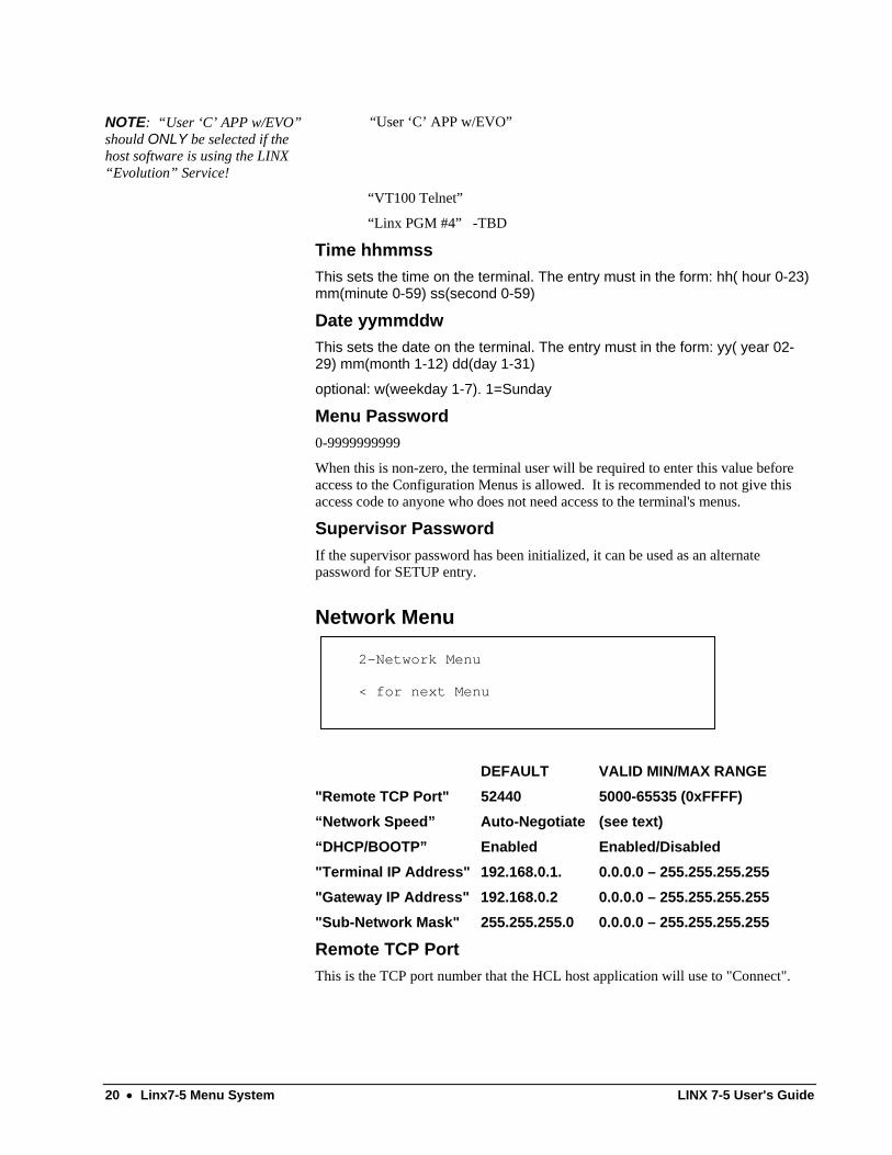
Network Menu
2-Network Menu
< for next Menu
DEFAULT VALID MIN/MAX RANGE
"Remote TCP Port" 52440 5000-65535 (0xFFFF) “Network Speed” Auto-Negotiate (see text) “DHCP/BOOTP” Enabled Enabled/Disabled "Terminal IP Address" 192.168.0.1. 0.0.0.0 – 255.255.255.255 "Gateway IP Address" 192.168.0.2 0.0.0.0 – 255.255.255.255 "Sub-Network Mask" 255.255.255.0 0.0.0.0 – 255.255.255.255
Remote TCP Port This is the TCP port number that the HCL host application will use to "Connect".
20 • Linx7-5 Menu System LINX 7-5 User's Guide

Network Speed
This is the network connection speed. Auto-Negotiate will auto detect and “negotiate” the recommended speed. However, if network hardware has problems with this method, select a “fixed” speed.
DHCP/BOOTP This selects whether a “DHCP” server will be used to auto configure the network parameters. IF DHCP/BOOTP is set, then the IP addresses and Subnet mask settings are received from the server.
IP Network Address
This is 16-digit field that will accept TCP/IP Notation Addresses. In most cases your network administrator has a system for selecting IP addresses for new computers (hosts). Have this person assign the number to you. This will be a set of 4 decimal values that are separated by periods. As an example:
128.1.1.43
The first 2 or three numbers (not digits) will usually be the same on EVERY computer in your company. You need to make sure that the IP address you assign does not conflict with any other computer on your network.
You may be able to examine the \ETC\HOSTS file to get a list of all of the addresses in use at your company. If you are using a central Domain Name Server (a computer that keeps track of all the IP addresses) then you will need to go to that machine to get a good list. Select an IP address for your LINX that starts with the same 3 numbers and differs only in the last one.
SETTING THE ADDRESS ON A LINX WITH NO DECIMAL POINT
The Linx7-5 may have a limited keyboard without a decimal point, so separate the numbers with the IN or OUT key. After entering the new address, press ENTER then EXIT to get out of the menus.
SPECIAL NOTE FOR IP ADDRESSES: All IP address fields should be set to the configuration provided by a "Network System Administrator".
Arbitrary setting of these network parameters can create major network problems in the connected LAN!
The Terminal IP address is the IP address desired for the terminal, which should be assigned by the IT system administrator. The terminal does not allow dynamically assigned IP addresses (DHCP/BootP)
The Gateway IP address is the IP address of the local gateway, if one exists.
The terminal and the host application must have matching subnet masks.
The Sub-Network Mask is the required mask for the sub network so that the terminal can receive data packets.
Diagnostics Menu
3-Diagnostics
< for next Menu
LINX 7-5 User's Guide Linx7-5 Menu System • 21
Although this test menu can be operated in the same fashion as the other menus, (ie: "IN" moves forward and "OUT" moves back), these tests can be accessed directly by pressing the corresponding prefix letter: "1" to "F". Thus pressing '6' will go directly to the "LED Lamp Test". Pressing "ENTER" will execute the selected test and the "EXIT" key will halt the testing and return to the menu.
(see Linx7-5 User Diagnostics chapter for more info)
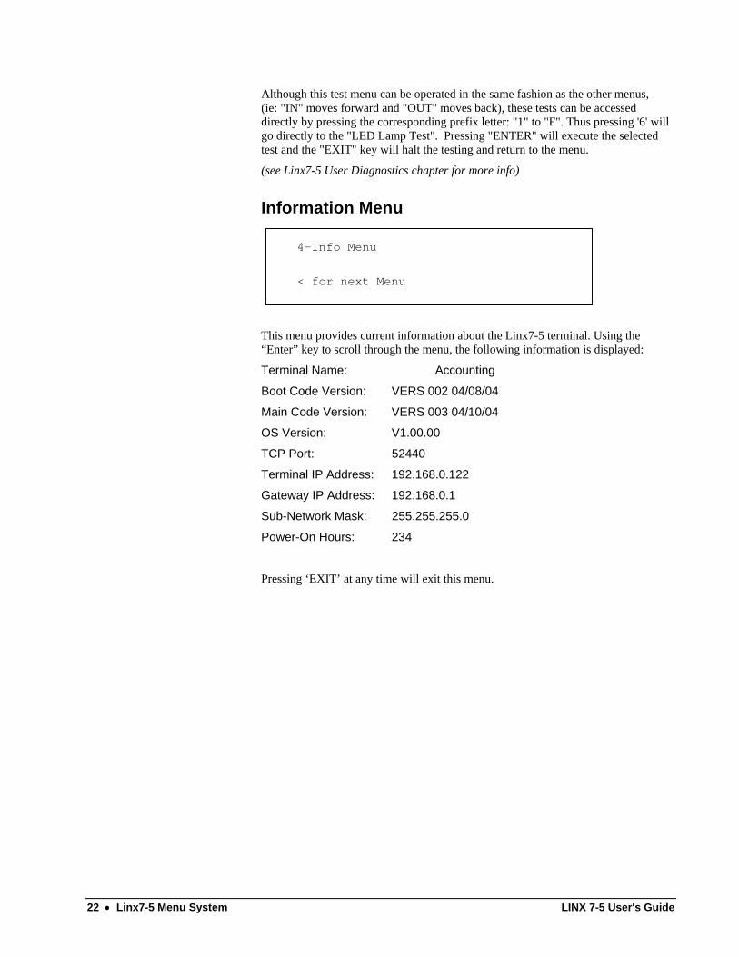
Information Menu
4-Info Menu
< for next Menu
This menu provides current information about the Linx7-5 terminal. Using the “Enter” key to scroll through the menu, the following information is displayed:
Terminal Name: Accounting
Boot Code Version: VERS 002 04/08/04
Main Code Version: VERS 003 04/10/04
OS Version: V1.00.00
TCP Port: 52440
Terminal IP Address: 192.168.0.122
Gateway IP Address: 192.168.0.1
Sub-Network Mask: 255.255.255.0
Power-On Hours: 234
Pressing ‘EXIT’ at any time will exit this menu.
22 • Linx7-5 Menu System LINX 7-5 User's Guide
Linx7-5 User Diagnostics
Keypad/Barcode/MSR Test NOTE: If a proximity reader is connected and is “enabled”, this test will also verify prox operation.
This test will echo all keypad keys, barcode and magnetic swipe data to the LCD display.
Display Test This test will display all displayable characters on the LCD display.
Destructive DRAM Test This test will verify that the SDRAM memory can be tested with the following data patterns:
DATA: 0x55555555, 0xAAAAAAAA, 0x00000000
Destructive SRAM Test WARNING: Since the SRAM contains the terminal configuration parameters, a power cycle MUST be performed after this test:
On Power-on, the “Boot Diagnostics” will execute (as described in the Preface) and the terminal will boot up normally but with “default” parameters. Consequently, the user MUST enter Setup before using the terminal.
This test will verify that the SRAM memory can be tested with the following data patterns:
DATA: 0x55555555, 0xAAAAAAAA, 0x00000000
LINX 7-5 User's Guide Linx7-5 User Diagnostics • 23

Time Display This test will display the current time and date. The display will auto-update when the time changes at 1second intervals.
LED Lamp Test This test will cycle all of the LED lamps in sequence. It is the user's responsibility to verify correct operation!
COM Loopback Test This test will prompt the user for two parameters used by the test:
Port(0,1) (0=COM1 1=COM2)
BAUD (0-6) 0=1200 1=2400 2=4800 3=9600 4=19200 5=38400 6=57600
On ‘ENTER” the test will start and display the results:
“Testing Pass: xxxxxxxx Fail: xxxxxxxx”
Pressing the ‘EXIT” key will stop the test.
COM Transmit Test This test will prompt the user for two parameters used by the test:
Port(0,1) (0=COM1 1=COM2)
BAUD (0-6) 0=1200 1=2400 2=4800 3=9600 4=19200 5=38400 6=57600
The test message is “The Quick Brown Fox Jumps Over the Lazy Dogs Back”.
On ‘ENTER” the test will start and display the results:
Line1: “Testing COMx Transmit at xxxxx BAUD”
Line2: “TxPackets: xxxxxxxx
Pressing the ‘EXIT” key will stop the test.
COM Receive Test This test will prompt the user for two parameters used by the test:
Port(0,1) (0=COM1 1=COM2)
BAUD (0-6) 0=1200 1=2400 2=4800 3=9600 4=19200 5=38400 6=57600
The test message is “The Quick Brown Fox Jumps Over the Lazy Dogs Back”.
On ‘ENTER” the test will start and display the results:
24 • Linx7-5 User Diagnostics LINX 7-5 User's Guide

Line1: “Testing COMx Receive at xxxxx BAUD”
Line2: “RxPkts: xxxxxxxx RxErrs: xxxxxxxxx
“Pressing the ‘EXIT” key will stop the test.
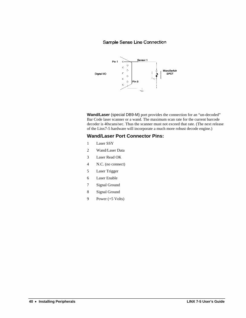
Sense Lines Test This test will verify that the Sense lines operate.
Please Note: This test MUST be performed with a special test board installed on J7 (Digital I/O Connector).
Control Lines Test This test will verify that the Control lines operate.
Please Note: This test MUST be performed with a special test board installed on J7 (Digital I/O Connector).
Vsmart FIU Test See “Post Assembly Verification in Appendix ‘F’ for more information.
This test will verify that the Bioscript Vsmart Fingerprint Identification Unit is configured correctly and is operational. A test card with a fingerprint template is required for this test.
Ethernet Internal Lpbk This test will verify that the Ethernet can operate in internal loopback via the Level-One(Intel) PHY I/F.
Ethernet Host Ping Test This routine will execute the ICMP ping command to the user requested Host IP address. This IP address must be entered when prompted by the test.
Reset PowerUP This test will reset the terminal similar to a power-on.
Reset to Defaults Note: All user settings will be lost except for network parameters!
This routine will reset the terminal configuration to defaults. Then the terminal will be
re-booted after configuration has been saved.
LINX 7-5 User's Guide Linx7-5 User Diagnostics • 25

Linx7-5 Web Server
Web Server Overview The Linx7-5 Web Server can be used to view terminal statistics, configure the terminal and perform simple maintenance tasks, such as rebooting the terminal. The web server is accessed via a web browser such as Internet Explorer or Netscape Communicator. The newer versions of the browsers must be used to provide all of the functionality of the web pages. IE5.0 and Netscape 6.0 (or later) have the capabilities required.
To view the main menu page execute the following: Assuming the Linx7-5 IP address = 15.126.45.23
step #1: Open the browser of your choice
step #2: In the URL field, type "http://15.126.45.23" or "15.126.45.23" only - press <enter>
The “Main Menu” page of the requested Linx7-5 terminal should have been loaded.
26 • Linx7-5 Web Server LINX 7-5 User's Guide

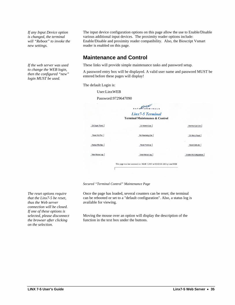
Information and Statistics These links will display read-only information pages to the user.
LINX 7-5 User's Guide Linx7-5 Web Server • 27

28 • Linx7-5 Web Server LINX 7-5 User's Guide

Setup and Configuration If the web server was used to change the WEB login, then the configured “new” login MUST be used.
These links will display configuration pages that provide the user remote setup capability. The pages allow the user to configure the terminal, network and barcode parameters. The menu options are identical to the internal menu system of the terminal. However, the “Barcode” menu options are ONLY available via the web server.
A password entry box will be displayed. A valid user name and password MUST be entered before these pages will display!
The default Login is:
User:LinxWEB
Password:9729647090
LINX 7-5 User's Guide Linx7-5 Web Server • 29

Secured “Terminal Setup” Page
If the “Application Mode” option is changed, the terminal will “Reboot” to invoke the new mode.
The terminal configuration options on this page are identical to the menu options described in the “Linx7-5 Menu System” chapter, except for the “Configure DST” option. This link will provide another configuration page for Daylight Savings Time Control.
30 • Linx7-5 Web Server LINX 7-5 User's Guide

Secured “Daylight Savings Time Control” Page
The “date” and “time fields MUST also be filled to activate a re-sync, especially if the DST parameters have been modified!
The DST (Daylight Savings Time) configuration web page is used to Enable or Disable automatic DST time adjustments. The start and end times are completely configurable via the entry fields. The start and end weeks denote the Sunday of the week when the DST starts and terminates respectively. The options are 1-5, where “1” indicates the First week and “4” indicates the 4th week. If “5” is used, the “LAST” week is selected. The last week may be the 4th or 5th dependent upon the month.
LINX 7-5 User's Guide Linx7-5 Web Server • 31

Secured “Network Setup” Page
If any Network option is changed, the terminal will “Reboot” to invoke the new settings.
The Network configuration options on this page are identical to the menu options described in the “Linx7-5 Menu System” chapter, except for the “Host InActivity Timeout “ option. This option configures the timeout before the terminal auto-disconnects. The setting is 0-120 minutes. 0=No Timeout 120=2 hours.
32 • Linx7-5 Web Server LINX 7-5 User's Guide

Secured “Barcode Setup” Page
This page allows the user to remotely configure the barcode decoder options. These configuration options are NOT available in the local menu system. Since Input devices have numerous settings, it was decided that it would be more efficient for the user to configure via the web. As more input devices are added in future releases, these will be added to the web configuration pages.
LINX 7-5 User's Guide Linx7-5 Web Server • 33

DEFAULT VALID MIN/MAX RANGE
"Code 39 Enable" Enabled Enabled/Disabled
“Industrial 2 of 5 Enable” Disabled Enabled/Disabled
“Interleaved 2 of 5 Enable” Disabled Enabled/Disabled
"UPC/EAN Enable" Disabled Enabled/UPC-EAN-JAN Enable/UPC Only
"Codabar Enable" Disabled Enabled/Disabled
"Code 128 Enable" Disabled Enabled/Disabled
“Code 39 Check Digits Enable”
Disabled Enabled/Disabled
“Code 39 ASCII Mode” Normal Normal/ASCII/Only Normal
“I2 of 5 Check Digits Enable”
Disabled Enabled/Disabled
“I2 of 5 Minimum Length” 0 0/4-32 (0 = any length)
“UPC Supplements” None None/2 Digit/5 Digit/ 2 and 5 Digit
“Laser Retry Enable” Disabled Enabled/Disabled
Secured “More Input Device Setup” Page
34 • Linx7-5 Web Server LINX 7-5 User's Guide
If any Input Device option is changed, the terminal will “Reboot” to invoke the new settings.
The input device configuration options on this page allow the use to Enable/Disable various additional input devices. The proximity reader options include: Enable/Disable and proximity reader compatibility. Also, the Bioscript Vsmart reader is enabled on this page.
Maintenance and Control If the web server was used to change the WEB login, then the configured “new” login MUST be used.
These links will provide simple maintenance tasks and password setup.
A password entry box will be displayed. A valid user name and password MUST be entered before these pages will display!
The default Login is:
User:LinxWEB
Password:9729647090
Secured “Terminal Control” Maintenance Page
The reset options require that the Linx7-5 be reset, thus the Web server connection will be closed. If one of these options is selected, please disconnect the browser after clicking on the selection.
Once the page has loaded, several counters can be reset; the terminal can be rebooted or set to a "default configuration". Also, a status log is available for viewing.
Moving the mouse over an option will display the description of the function in the text box under the buttons.
LINX 7-5 User's Guide Linx7-5 Web Server • 35

Secured “Password Control” Maintenance Page
If spaces are required, use the underscore (‘_’) character to separate work
The password control page allows the user to modify the login for the WEB and FTP servers. The “Secret Question” field is used to allow password recovery. The question (max 39 characters) will be stored and used as a means of recovering the passwords.
Please note: Once the “defaults” have been changed, the new defined user/password combination MUST be used to access either the WEB or FTP server.
36 • Linx7-5 Web Server LINX 7-5 User's Guide

Secured “Password Recovery” Maintenance Page
The Password recovery page allows the user access to the defined user/passwords using the “Secret Question”. If the user enters the correct “Secret Answer”, the return page will display the currently configured WEB and FTP login information.
LINX 7-5 User's Guide Linx7-5 Web Server • 37
Installing Peripherals
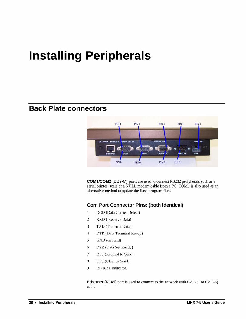
Back Plate connectors
COM1/COM2 (DB9-M) ports are used to connect RS232 peripherals such as a serial printer, scale or a NULL modem cable from a PC. COM1 is also used as an alternative method to update the flash program files.
Com Port Connector Pins: (both identical) 1 DCD (Data Carrier Detect)
2 RXD ( Receive Data)
3 TXD (Transmit Data)
4 DTR (Data Terminal Ready)
5 GND (Ground)
6 DSR (Data Set Ready)
7 RTS (Request to Send)
8 CTS (Clear to Send)
9 RI (Ring Indicator)
Ethernet (RJ45) port is used to connect to the network with CAT-5 (or CAT-6) cable.
38 • Installing Peripherals LINX 7-5 User's Guide
Power (3-pin Molex) port connects to the +5V-DC switching Power Supply provided with the Linx7-5 terminal.
Power Connector Pins: 1 +5 Volts
2 Chassis/Earth Ground
3 Signal Ground
Due to PC trace limitations, the relay current must not exceed 0.5 amps
Digital I/O (DB9-F) port is used to connect external switches, relays and any other devices that can be monitored via a sensor, or controlled via a control line. There are 3 TTL control lines that provide 20ma for driving solid-state relays or similar. One more control line uses a relay that may switch power to a load directly. The relay is rated: 0.5A @125VAC or 1A @24VDC (max VDC=60v).
Digital I/O Connector Pins: 1 Sensor Line # 1 Input
2 Sensor Line #2 Input
3 Sensor Line #3 Input
4 Relay Wiper (Control line #4)
5 Relay NO Output (Control Line #4) (NO=Normally open)
6 TTL Control Line #1 Output
7 TTL Control Line #2 Output
8 TTL Control Line #3 Output
9 Signal Ground
LINX 7-5 User's Guide Installing Peripherals • 39
Wand/Laser (special DB9-M) port provides the connection for an “un-decoded” Bar Code laser scanner or a wand. The maximum scan rate for the current barcode decoder is 40scans/sec. Thus the scanner must not exceed that rate. (The next release of the Linx7-5 hardware will incorporate a much more robust decode engine.)
Wand/Laser Port Connector Pins: 1 Laser SSY
2 Wand/Laser Data
3 Laser Read OK
4 N.C. (no connect)
5 Laser Trigger
6 Laser Enable
7 Signal Ground
8 Signal Ground
9 Power (+5 Volts)
40 • Installing Peripherals LINX 7-5 User's Guide

Appendixes
Appendix A
10/100 Mb Ethernet Installation Guidelines The RJ45 connector has 2 integral status LEDs that can help to diagnose network problems.
The Green LED indicates Media Speed: On = l00 MB
Off = 10 MB
The Orange LED indicates Link Status: On = Link is Up
Off = Link is Down
LINX 7-5 User's Guide Appendixes • 41

Appendix B
Updating Code Blocks In Flash
Updating FLASH via Ethernet: The program and operating system components can be updated remotely using an Ethernet connection. However, at this time, only the Host program can send the commands necessary to update the flash memory containing the OS and program.
Following are the steps the host must perform to update the program flash using the ethernet:
1. The host must start a FTP Client with the IP Address of the remote Linx7-5. (ie: ftp 192.168.234.15 or equivalent)
2. The host must issue the "user command" to get the login prompt with a correct username/password combination.
3. If the connection has been made, enter "binary" mode. This will set the FTP server to expect binary octets. (instead of ASCII).
4. Send the desired 'S19' file to the Linx7-5 using the "put" command.
5. If the file transferred correctly, "quit" the FTP connection.
Filename MUST be the name of the ‘S19’ file FTP’d previously.
7. Now that the 'S19' file has been transferred to the Linx7-5 file system, the LINX Supplied OS Update Utility program must be used. Select the .S19 file from the directory and execute.
8. The Host should immediately disconnect from the Linx7-5, since all operating system processes will be halted. If the file is found by the OS, flash updating will commence and when completed, the terminal will reboot.
9. After approximately 10-15 seconds, the Host program should try to "ping" and ensure that the Linx7-5 is alive and well. If not, a local administrator may have to intervene to determine why the terminal did not respond.
42 • Appendixes LINX 7-5 User's Guide

Updating FLASH via COM1 Port: The RS232 port can only be used for flash updates while in the boot code block. On Power-Up, the message "Firmware Validation in Progress" signals a 2 second wait for the "CLEAR" key to be pressed and held down. If pressed, the code will enter a RS232 upload program that will be indicated by the following message: "NOTICE: READY FOR FLASH CODE UPLOAD". Once, this message appears the "CLEAR" key may be released and the "S19" file upload can be started.
To upload the S19 file, the RS232 port must be connected to a PC running a terminal emulation program such as "PROCOMM". The connection must be made using a normal serial cable and a RS232 NULL Modem converter. The converter must then be connected to the Linx7-5 COM1 RS232 port The COM port setting must be 9600 BAUD, No Parity, 8 Data Bits and 1 STOP bit. (9600N81 PC default)
Once the connection is complete, the terminal emulation program should send the "S19" file via an ASCII transfer. Once the transfer has completed, the upload code will verify the S19 file. If the file passes an integrity check, the following message will appear: "File accepted. Flash programming started." then the desired flash block will be programmed. The terminal will be rebooted and if the programming was successful, the terminal will boot into the normal startup code.
LINX 7-5 User's Guide Appendixes • 43

Appendix C
Using FTP.EXE - Windows Command Line FTP Client with the Linx7-5 The initial connection commands are as follows:
Assume the Linx7-5 IP address is 56.23.145.23....
step #1: type "ftp 56.23.145.23" <enter>
the following messages should appear:
"connected to 56.23.145.23"
"220 service ready"
"user <56.23.145.23:<none>>:"
step #1a: press <enter>
"ftp>" should appear
step #2: type "user" <enter>
the following message should appear:
"Username"
step #3: type AnOnYmOuS <enter> (NOTE: must be exact case!)
(this is the only default user name)
However, if the FTP login has been changed via the web server, then the “new” user/password MUST be used!
The following message should appear:
"331 User name ok, need password"
"Password:"
step #4: type AnOnYmOuS <enter> (NOTE: must be exact case!)
(this is the only default password)
However, if the FTP login has been changed via the web server, then the “new” user/password MUST be used!
If password was entered correctly, the following message
is displayed:
"230 User logged in"
"ftp>"
Now FTP commands can be entered. The most useful FTP commands for this FTP client are listed in Table 1.
step #5: To EXIT session - type "bye" (or "quit") <enter>
44 • Appendixes LINX 7-5 User's Guide
COMMON FTP OPERATIONS
LIST Directory: To get a directory listing of the remote Linx7-5, type "ls". This will result in a list of the filenames in the current directory. Using "LS" will result in a verbose listing that can distinguish Linx7-5 stored files. Use “PWD” (Print Working Directory) to ensure that you are located in the desired drive/directory.
DOWNLOAD file to Linx7-5 default directory: To download a file to the Linx7-5, type "put" (or send) filename. This will load the file and the session should respond with a message indicating that the operation was successful. The file can be seen if "LS" is executed. The downloaded file will the first shown.
DOWNLOAD file to Linx7-5 user directory: Important Note: The “user” file area (DRIVE “D”) is only 250k in battery-backed SRAM. Since this area is limited in size, this area must ONLY be used for files that are required by the user application such as the “.CFG” files.
Note: to download a file first type "cd" D:\ to change the working directory to the SRAM disk. This will allow FTP to transfer the file into a "nonvolatile" file area. Next type "put filename" (ie:CLK.CFG) and the file will be loaded to the user file area. Typing "LS" will show the file at the end of the directory listing as "\CLK.CFG".
DELETE a file from Linx7-5 default directory: Any file loaded via FTP can be deleted from the remote directory using "del filename". Executing "LS" will reveal that the file has been removed. Ensure that you are located in the correct drive!
LINX 7-5 User's Guide Appendixes • 45
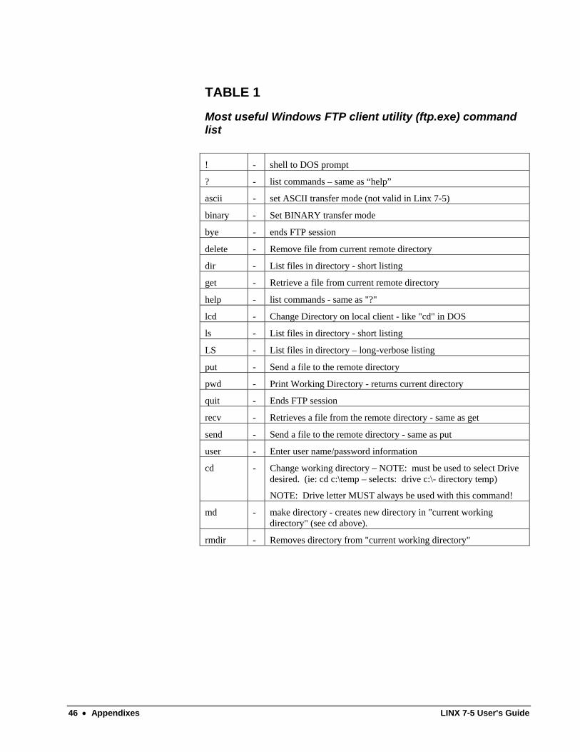
TABLE 1
Most useful Windows FTP client utility (ftp.exe) command list
! - shell to DOS prompt
? - list commands – same as “help”
ascii - set ASCII transfer mode (not valid in Linx 7-5)
binary - Set BINARY transfer mode
bye - ends FTP session
delete - Remove file from current remote directory
dir - List files in directory - short listing
get - Retrieve a file from current remote directory
help - list commands - same as "?"
lcd - Change Directory on local client - like "cd" in DOS
ls - List files in directory - short listing
LS - List files in directory – long-verbose listing
put - Send a file to the remote directory
pwd - Print Working Directory - returns current directory
quit - Ends FTP session
recv - Retrieves a file from the remote directory - same as get
send - Send a file to the remote directory - same as put
user - Enter user name/password information
cd - Change working directory – NOTE: must be used to select Drive desired. (ie: cd c:\temp – selects: drive c:\- directory temp)
NOTE: Drive letter MUST always be used with this command!
md - make directory - creates new directory in "current working directory" (see cd above).
rmdir - Removes directory from "current working directory"
46 • Appendixes LINX 7-5 User's Guide

Appendix D
LINX 7-5 MEMORY MAP
F001FFFF
F0010000
CPU-internal I/O - 64K
F00007FF
F0000000
CPU-internal Memory - 2K
042000FF
04200000
Real-Time-Clock - 256 bytes
040000FF
04000000
CPLD - 256 bytes
0307FFFF
03000000
(256K Drive D: - Non-Volatile)
Static RAM - 512K bytes
02FFFFFF
02000000
(>8MB Drive C: - Volatile)
16 MB Synchronous DRAM
001FFFFF
00180000
USER App code space - 512K bytes
0017FFFF
00080000
OS code 1.0 MB
0007FFFF
00020000
MAIN CODE - 384K
0001FFFF
0001C000
Main Parameter Tables - 32 K
0001BFFF
00018000
Boot Parameter Tables - 32 K
00017FFF
00000000
BOOT CODE - 96 K
LINX 7-5 User's Guide Appendixes • 47

Appendix E
Setup of the Bioscrypt V-Smart reader on the Linx7-5 Terminal The Bioscrypt V-Smart FingerPrint reader is a device that can be connected to Linx7-5 terminals to provide "Biometric" security for any application that may require it. The Bioscrypt V-Smart reader is a "double-validation" device that requires a fingerprint template on a "MiFare" or "IClass" Smart Card and the corresponding matching fingerprint placed on the sensor before validation is successful. This increases security since "both" are always required. However, to allow the V-Smart to operate with the Linx7-5 terminal, the V-Smart and the terminal must be set up correctly.
Before setup, please read:
"V-Prox/V-Flex/V-Pass/V-Smart/V-Station Operations Manual" and pay special attention to: Appendixes A,D, and E!
On the V-Smart Reader: NOTE: You may have to remove the screw that holds the bottom cover. An Allen wrench has been provided for this purpose.
NOTE: The PC RS232 setup is:57600 N 8 1
1. Connect the supplied RS232 to RJ11 cable to the PC and the RJ11 jack on the bottom of the V-Smart reader. This is the "AUX" port and will be used to pre-configure the V-Smart before attaching to the Linx7-5.
2. Using the "Veri-Admin" software, set up the terminal as per the instructions in the "Veri-Series: Setup Guide" document that is supplied with the V-Smart reader.
3. Start the "Veri-Admin" software on the PC attached to the V-Smart. Execute "Network Setup" and configure the reader as described.
4. After network has been set up, click on the reader ID in the network configuration to enter the "Unit Parameters" dialog. All settings should stay at default - click on the "Communications" tab.
5. Communications TAB setup:
a. The HOST and AUX port MUST be left at 56700 BAUD
b. Execute "Test Communications" to verify ports (use broadcast mode)
c. Observe that the "Host Mode" is currently set to "0" This will be changed before exiting the entire setup.
(Please follow instructions in Appendix E)
d. Save "Unit Parameter" settings and enter "Smart Card Security Settings" dialog. A "SiteKey" should be created that matches the SiteKey that will stored on the smart card.
Store this SiteKey in the V-Smart reader as instructed. This allows "ONLY" the smart cards that have the correct SiteKey to be validated...
PLEASE NOTE: This step is to be executed ONLY if the V-Smart reader (now in configuration) will be connected directly to a Linx7-5 Terminal. For development and to provide fingerprint enrollment, the "AUX" port can continueto be used. For Linx7-5 development, connect the RS232 to RJ11 cable directly to one of the terminal COM ports and the setup of the V-Smart reader is complete.
48 • Appendixes LINX 7-5 User's Guide
This mode is NOT secure! For deployment, the AUX port should be locked-down by attaching the supplied cover with the "Allen Head" screw provided.
Linx7-5 communications should be via the RS485 port as stated in the next paragraph.
e. Once the SiteKey has been saved to the V-Smart, the reader must be configured to allow communications to the Linx7-5 terminal. Go back to the "Unit Parameters" "Communications" TAB and change the "Host Mode" to Mode #2.This allows the RS485 to be activated and the AUX port to be disconnected! Click the "Apply" button.
NOTE: After this has been executed, the PC will no longer be able to communicate without a RS485 to RS232 converter attached!!!!!!
f. Lock the AUX port using the supplied cover and screw. This will eliminate re-configuration without the RS485 "Host" port issuing a special re-enable AUX port command.
On the Linx7-5 terminal: 1. If the V-Smart reader has been re-configured to use the RS485 port for
the "Host", connect as per RS485 cabling instructions (see appendix F). Otherwise, the RS232 to RJ11 cable can be used. Connect the reader to either COM1 or COM2.
Note: This test will execute with the FIU Reader configuration set to "Disabled" or "Enabled".
2. Using a "Pre-enrolled" smart card, the "Reader to Terminal" communications can be verified using the "FIU Reader Test" (menu option: 'C') in the Diagnostics menu of the terminal. Follow the instructions and ensure that the reader is operational.
3. "Enable" V-Smart via the password-protected "More Input Devices" web page. This MUST be set to allow HCL, ITAS and 'C' user applications to use the V-Smart.
LINX 7-5 User's Guide Appendixes • 49

APPENDIX F
Cabling requirements to use the V-Smart with the Linx7-5
Parts required:
1. Bioscrypt V-Smart MiFare reader w/15pin pigtail
2. Linx supplied RS232 to RS485 converter board
3. +12V power supply (V-Smart and Converter both req. +12v)
4. +5V Linx 7-5 power supply
5. Short RS232 DB9 female-female extension cable.
Assembly Instructions:
1. Find the following wires in the V-Smart Pigtail and strip ends:
(if not already stripped!)
a. blue/black wire: RS485(-)
b. blue wire: RS485(+)
c. black wire: Power GND
d. red wire: Power Input (+12v)
e. green/yellow wire Earth GND
2. Tie off all other wires - ensure none are shorting..
Note: The following connections are to be made via the tinned leads on the converter board using the crimp terminals provided with the V-Smart installation kit. Converter Board Tinned leads:
Wire Color Signal Name EGND Green Earth Ground +12 Red +12v DC GND Black 12v DC Common 485+ Blue RS485+ 485- Blue/Black RS485- x------------------------------------x | x-R11-x | | +--------------------+ | | MH | X X X X X | MH | MH=Mounting Hole | +--------------------+ | +------------------------------------+ EGND +12 GND 485+ 485-
3. Connect pigtail blue/black wire (RS485-) and converter Blue/Black wires using a crimp terminal. (total: 2 wires)
50 • Appendixes LINX 7-5 User's Guide

4. Connect pigtail blue wire (RS485+) and converter blue wire using a crimp terminal. (total: 2 wires)
5. Connect pigtail black wire (Power GND) and 12v supply '-' black lead and converter black wire using a crimp terminal. (total: 3 wires)
6. Connect pigtail red wire (Power Input) and 12v supply '+' white lead and converter red wire using a crimp terminal. (total: 3 wires)
7. Connect pigtail green/yellow wire (Earth GND) and the 12v supply shrink-wrapped Earth GND lead and converter green wire using a crimp terminal. (total: 3 wires)
8. If the V-SMart is ready for deployment, connect one end of the RS232 extension cable to the desired COM port of the Linx7-5.
Go to step #10
If not already configured, then the V-Smart must be configured.
These are the two possible connection methods for configuration via a RS232 COM port on the Configuration PC that has the Veri-Admin software installed:
If the V-Smart reader "Host Mode" has already been changed to
Mode #2, (HOST = RS485), the RS232 jack on the converter board can be directly cabled to a PC COM port.
==>> Otherwise, if the "Host Mode" is still at "DEFAULT" Mode #0
(HOST = AUX)), then the RS232 to RJ11 cable supplied with the V-Smart can be used.
(see Appendix E for configuration information). 9. Connect the other end of the extension cable to the DB9 connector of the
RS232-RS485 converter board.
10. If available, connect the AC 'Y' adapter power cord to both power supplies. Otherwise, there must be 2 AC power cords.
11. If the Linx7-5 is ready for deployment, secure the Power Supplies to ensure stability.
(ie: use Velcro, double-sided tape, or tie-wraps)
POST ASSEMBLY VERIFICATION: 1. Power-On the terminal.
2. Enter Setup by pressing the "F1" key as indicated on the display.
3. Enter "Diagnostics" menu - press 'C' then "Enter" to enter the "FIU Reader Test". Press '1' or '2' to select the COM port for testing and execute the following instructions for verification of the installation.
4. Using a pre-enrolled Smart Card:
a. Hold the card in front of the V-Smart card reader (unit without fingerprint sensor). The V-Smart status LED should turn "Yellow".
b. Place the enrolled finger on the sensor. Wait for a "Beep". If it reads, the LED will turn "Green" else it will turn "Red".
c. If "Red" return to step "a".
LINX 7-5 User's Guide Appendixes • 51

d. If "Green" the FIU diagnostic should display the ID and verification percentage.
After ensuring the the V-Smart reader has been "Enabled" via the web interface, the Linx7-5 terminal security system is ready for use.
52 • Appendixes LINX 7-5 User's Guide

Appendix G
Using the VT100 Terminal Emulation on the Linx7-5 IMPORTANT NOTE:
To effectively use the VT100 Terminal Emulation, a "QWERTY" keyboard should be installed on the Linx7-5!
The Linx7-5 terminal has a "built-in" VT100 emulation mode which can be enabled by changing the "Application Mode" in the "Terminal Menu" to "VT100 Telnet". The only extra operational requirement is a configuration file named: "TC.CFG" that MUST be loaded to the SRAM Non-Volatile drive (Drive D:) of the terminal via FTP. Linx supplies a "Full" version of this file (sample follows) or it can be created using a simple text editor.
NOTE: The ONLY entry that MUST be present is the "SERVER IP=" line which indicates the server's IP address for the TELNET client connection. All others will default to allow a connection to a TELNET Server on Port #23.
ie: SERVER IP=10.4.25.1 <line feed> - A line feed is mandatory!
VT100 Support: The Linx7-5 VT100 Terminal Emulation supports the following VT100/VT52 functions:
Note: ANSI Mode is the default on Power up. PF1-PF4 keys Normal and Application Mode
Numeric Keypad Keys Normal and Application Mode
Cursor Key Mode Using "ALT" with cursor key to generate VT100 codes
Set VT52 Mode Change to VT52 operation
Set ANSI Mode Change to ANSI operation (from VT52 mode)
ALL Cursor control escapes - Both ANSI/VT52 modes
ALL ERASE Line/Screen escapes - Both ANSI/VT52 modes
TABs and TAB stops
Cursor Position Report - ANSI only
Status Report - ANSI only - Device Attibutes
Terminal RESET - ANSI only
Terminal Identify - VT52 only
Set/Reset Modes:
Line Feed Mode
Cursor Key Mode
Application Mode
LINX 7-5 User's Guide Appendixes • 53
ANSI/VT52 Mode
Wraparound Mode
KeyPad Mode
Set/Reset VT100 LEDs - uses LEDs @ F7-F10
Local and Remote ECHO of keys: determined by Server "ECHO" negotiation
The following keys can be defined in TC.CFG file:
AYT ("Are You There") - default = F10
AO ("Abort Output") - default = F8
IP ("Interrupt Process") - defualt = F9
The following keys are defined by the Linx7-5:
ALT-EXIT = "ESC"
ALT-LEFT = VT100 Left Arrow key codes
ALT-RIGHT = VT100 Right Arrow key codes
ALT-DOWN = VT100 Down Arrow key codes
ALT-UP = VT100 Up Arrow key codes
F1-F4 = VT100 PF1-PF4 keys
Special Note: Using the "ALT" key (instead of a CTRL key) all of the ASCII CONTROL characters can be generated by the Linx7-5.
(ie: ALT-H = "Backspace" equivalent to: ^H or CTRL-H)
54 • Appendixes LINX 7-5 User's Guide

SAMPLE TC.CFG FILE (as supplied by LINX) NOTES:
1. All lines that start with '#' or '[' are considered COMMENT lines
2. All settings MUST be CAPITALIZED!
3. Any setting not in the file will be set to zero or a standard default
4. Setting must be defined immediately after the '=' character-no spaces
[Telnet Client Config File]
[Server]
# Set TELNET Server IP Address (ie: 10.45.234.2)
SERVER IP=10.10.50.132
# Set TELNET Server TCP Port (default = 23)
TELNET PORT=1023
[Control]
# TELNET Logging to file "TC.LOG" (Non-Volatile Drive D:) { Yes = 1, No = 0 }
# Note: Logging should normally NOT be enabled due to "security" issues
LOGGING=0
# TELNET InActivity Timeout (in seconds) { 0 = NO timeout }
INACTIVE TIMEOUT=0
# Use RFIdeas Proximity Reader { Yes = 1, No = 0 }
USE PROX=0
# Use BiosCrypt (F)ingerprint (I)dentification (U)nit { Yes = 1, No = 0 }
USE FIU=0
[Key mapping]
#Note: F1-F4 provides VT100 PF1-PF4 function
# Function Key # to provide (AO) "Abort Output" default=F8 {F:5-10}
AO KEY=8
LINX 7-5 User's Guide Appendixes • 55

# Function Key # to provide (IP) "Interrupt Process" default=F9 {F:5-10}
IP KEY=9
# Function Key # to provide (AYT) "Are You There" default=F10 {F:5-10}
AYT KEY=10
56 • Appendixes LINX 7-5 User's Guide

LINX 7-5 User's Guide Appendixes • 57