liny.csie.nctu.edu.twliny.csie.nctu.edu.tw/document/iottalk_manual-eng.docx · web viewa motion...
TRANSCRIPT

IoTtalk User Manual
Yi-Bing Lin and Yun-Wei Lin
College of Computer Science
National Chiao Tung University
Section 1. Introduction
An IoT device can be characterized by its functionalities or “device features”. For the
purpose of description, we define a device feature (DF) as a specific input or output
“capability” of the IoT device. For example, a wearable ring with the temperature sensor has
the input device feature (IDF) called “Temperature”. A pair of wearable glasses with the
optical head-mounted display has the output device feature (ODF) called “Display”. An IoT
device may be connected to the network (i.e., Internet) using wireless communications
directly or indirectly through a smartphone. If so, the corresponding software called network
application is developed and executed by a server in the network side, which receives or sends
the messages from/to the IoT device. When the IDFs produce new values, the IoT device will
inform the network application to take some actions, and the network application may send
the result to the ODF of an IoT device. With this view, the IoT devices interact with each
other through their features, and we say that the network application “maps” the IDFs to the
ODFs.
IoTtalk is a platform for IOT device interaction based on the concept of device feature.
When the IoT devices are connected, IoTtalk automatically generates/reuses the application
1
software for these sensors so that every input IoT device can be conveniently connected to an
output IoT device.
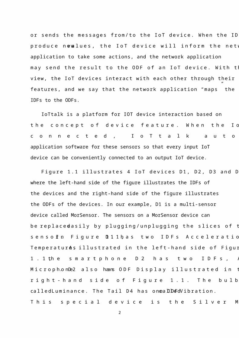
Figure 1.1 illustrates 4 IoT devices D1, D2, D3 and D4, where the left-hand side of the
figure illustrates the IDFs of the devices and the right-hand side of the figure illustrates the
ODFs of the devices. In our example, D1 is a multi-sensor device called MorSensor. The
sensors on a MorSensor device can be replaced easily by plugging/unplugging the slices of
the sensor. In Figure 1.1, D1 has two IDFs Acceleration and Temperature. As illustrated in the
left-hand side of Figure 1.1, the smartphone D2 has two IDFs, Acceleration and Microphone.
D2 also has an ODF Display illustrated in the right-hand side of Figure 1.1. The bulb D3 has
an ODF called Luminance. The Tail D4 has one ODF called Vibration. This special device is
the Silver Medal Award artwork “Transparent Organ” in Salon International Des Invention
[Huang2014]. The tail of this device wags based on the vibration strength received from its
Vibration.
Acceleration
Temperature
D1
Acceleration
Microphone
D2
Luminance
D3
Vibration
D4
NA1
NA2
NA3
D2
Display
1
2
3
4
Figure 1.1. Connections among D1, D2, D3, and D4
Lines (1)-(4) in Figure 1.1 illustrates how these IoT devices interact, where a line
connecting an IDF to an ODF represents interactions between the corresponding device
features in input and output IoT devices. Such interactions are implemented in Python
programs called network applications. In Figure 1.1, the dashed box NA1 represents the
network application NA1 that implements interactions (1) and (3) for D1, D2 and D3.
2
Similarly, NA2 implements interactions (2) for D1 and D2, and NA3 implements interactions
(4) for D2 and D4. Consider Line (2) as an example. This line links Temperature IDF (the
temperature sensor of D1) to Display ODF (the display of D2), which means that NA2
processes the temperature values sent from D1, and then displays the processed results on the
smartphone D2. If a network application handles the individual device features independently,
then we can write a software module for each device feature, and the network application can
be simply constructed by including these reusable DF modules. For example, the building
blocks for Line (4) in Figure 1.1 are shown in Figure 1.2, where the network application NA3
handles Microphone of D2 through the Microphone Module. This IDF module computes, e.g.,
the volume of Microphone, and passes the result to the Vibration Module. This ODF module
translates the received value to the vibration intensity. Then NA3 outputs this intensity to the
Vibration ODF to drive the vibration mechanism of D4.
Microphone
D2
Vibration
D4 Network Application
IDF Module (Microphone)
ODF Module (Vibration)
Figure 1.2. Software modules for microphone to vibration mapping NA3
Since the IDF and the ODF modules are independent of each other, these software
modules can be reused to build the network applications, and effectively speed up the
development of the IoT applications. Figure 1.1 shows that different IoT devices may have the
same IDFs/ODFs. For example, D1 and D2 have the same Acceleration IDF. Therefore, NA1
can reuse same software modules to implement the required tasks (i.e., Lines (1) and (3)) for
these similar DFs.
As we pointed out, the central concept of our approach is the DFs that can be classified based
on traditional and non-traditional human senses:
3

Sight: An IDF can be a camera with one DF-parameter “video format” or a color sensor
with three DF-parameters for red, green, and blue. An ODF can be a display with one DF-
parameter “format” to specify text, graphics, video, and so on. Another example of sight
ODFs is a light bulb with one-parameter DF called “Luminance”.
Hearing: An IDF can be a microphone with one DF-parameter “sound pressure level”
expressed in μPa or Pa. An ODF can be a speaker with the same DF-parameters as a
microphone, an automatic music playing machine driven by music scores, and so on.
Taste, smell, and chemoreceptor: The IDFs can be a carbon monoxide detector with one
DF-parameter “CO-level”.
Touch: The IDFs can be pressure sensors with one DF-parameter “pound per square inch”
(PSI), barometers with one DF-parameter “atmosphere” (ATM), and so on. Another
example of touch IDF is a button with one Boolean DF-parameter that takes values “on”
and “off”. The touch ODFs can be multi-stage switches with one integer DF-parameter.
Temperature: A temperature sensor has a DF-parameter for temperature degree Celsius or
Fahrenheit. Special thermometers that operate in very high or very low temperatures are
specified by their operation ranges [a, b].
Motion (including kinesthetic sense and acceleration): A location sensor can be an
outdoor GPS receiver or an indoor iBeacon receiver with three DF-parameters for
longitude, latitude and time. A motion sensor has three DF-parameters for three
dimensions. Examples of motion sensors are accelerometers, gyroscopes, and so on.
The input/output DFs can be vibration, speed, flow, etc.
Echolocation, electroreception and magnetoception: The IDFs can be an ultrasound sensor
with one DF-parameter “frequency” of the sound, a voltage sensor with one DF-parameter
4
“voltage” or a magnetometer with two DF-parameters for the strength and direction of the
magnetic field.
Based on the concept of device feature, we developed the IoT device feature
management system called IoTtalk. The IoTtalk architecture (Figure 1.3) includes two
domains: the network domain (Figure 1.3 (a)) and the device domain (Figure 1.3 (b)). The
network domain consists of four systems. The Creation, Configuration and Management
system (abbreviated as the IoTtalk; Figure 1.3 (c)) systematically categorizes the features of
the IoT devices, manages the functions to automatically configure connectivity of IDFs and
ODFs, and stores all related information in the Database system (DB; Figure 1.3 (d)). The
Execution and Communication system (EC; Figure 1.3 (e)) consists of two subsystems. The
Communication SubModule system (CSM; Figure 1.3 (f)) defines HTTP based RESTful API
(Application Programming Interface) for the Device Application (DA; Figure 1.3 (g)) to
deliver/retrieve the IDF/ODF information. When an IoT device registers/deregisters with the
EC, the DA instructs the CSM through the HTTP API to change the device status in the DB.
After the IoT devices have registered to the DA, they can transparently communicate with
each other through the EC. The Execution SubModule system (ESM; Figure 1.3 (h)) is
responsible for execution of network applications for the connected IDFs and ODFs. The GUI
(Figure 1.3 (i)) provides a friendly web-based user interface to quickly establish the
connections and meaningful interactions among the IoT devices. Through this GUI, a user
instructs the IoTtalk to execute desired tasks to create or set up device features, DF functions,
and connection configurations.
5

HTTP(Wi-Fi/3G/
LTE)DAI DAN
GUIDB
CCM
ESM
HTTPORM API
(Bluetooth/
Wi-Fi/ZigBee/…)
IoT DeviceIDA
Mobile DeviceEC
DA
CSM
ORM API
HTTPHTTP
ab
c
d
e
f
g h
ij
k
Device Domain Network Domain
lm
Figure 1.3. The IoTtalk architecture
In the device domain, the DA (Figure 1.3 (g)) is installed in a mobile device (e.g., a
smartphone). The IoT Device Application (IDA; Figure 1.3 (j)) connects to IoTtalk indirectly
through the DA. In the mobile device, the DA consists of two software components. The
Device Application to the Network (DAN; Figure 1.3 (k)) communicates with IoTtalk for
IDA registration and data exchange via Wi-Fi, 3G, or LTE. The Device Application to IoT
Device (DAI; Figure 1.3 (l)) communicates with the IoT device following the message format
specified by the IDA (typically a string delivered through Bluetooth, Wi-Fi, ZigBee, etc.).
Before an IoT device can be manipulated by IoTtalk, it must register to the CSM. The concept
of IoTtalk’s registration follows mobile telecommunications [Lin2001]. In mobile
telecommunications, the registration operation includes authentication, initialization of
encryption, and update of the mobile device location. Then the mobile device can attach to the
network and starts data sessions. In the current version of IoTtalk, application-level
authentication and encryption are not conducted in the registration operation. Instead, due to
the simple nature of IoT device, IoTtalk’s registration also includes attachment and setup of a
data session.
We have developed two versions of IoTtalk. In the network version, IoTtalk is implemented
on a server and is accessed via the Internet. The network version is appropriate for the user to
6
connect various IoT devices distributed in different networks. The network version also
supports multiple users for sharing their devices or functions. In the standalone version,
IoTtalk is implemented on a personal computer (e.g., a laptop or a desktop). In the current
standalone version, all IoT devices are connected to IoTtalk (the laptop) through a smartphone
(mobile device) using the Wi-Fi hotspot service. That is, the user only needs to turn on the
Wi-Fi hotspot service of the smartphone and let the laptop directly connect to it. In this way,
there is no need to use Wi-Fi AP or 3G/LTE base station for the link (k)-(m)-(f) in Figure 1.3,
and the smartphone D2 in Figure 1.1 can serve as the hotspot. Therefore, besides the role of
an IoT device, D2 also serves as the mobile device (Figure 1.3 (g)) and the wireless network
(Figure 1.3 (m)) in the connectively layer, where all IoT devices (D1, D2, D3, and D4)
connect to IoTtalk through D2. In this chapter, we assume that the IoT devices are connected
to IoTtalk through wireless communications. There are other scenarios that the IoT devices
are not wirelessly connected.
Section 2. GUI Operations
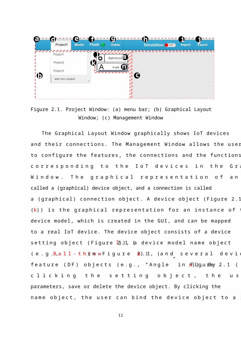
Figure 2.1 illustrates the Project Window of IoTtalk, which is divided into three parts:
the menu bar (Figure 2.1 (a)), the Graphical Layout Window (Figure 2.1 (b)), and the
Management Window (Figure 2.1 (c)). The menu bar has seven items. The “Project” item is a
pull-down menu (Figure 2.1 (d)) for the user to select a specific project. The “Model” item
(Figure 2.1 (e)) is another pull-down menu for choosing device models to be manipulated in
the Graphical Layout Window. The “Flush” item (Figure 2.1 (f)) is a button with an indicator
light to flush the states of the project when the project is suspended due to wrong setting. The
indicator light is green when the project is running and is red if the project is suspended. The
“Delete” item (Figure 2.1 (g)) is a button to delete the current project. The “Simulation
ON/OFF” item (Figure 2.1 (h)) is a toggle button to activate (in the “ON” mode) or deactivate
7

(in the “OFF” mode) the simulation function. The “Import” item (Figure 2.1 (i)) is a button to
import a project from a file. The “Export” item (Figure 2.1 (j)) is a button to export a project
to a file.
a
b c
d e f g h i j
kl m
n
Figure 2.1. Project Window: (a) menu bar; (b) Graphical Layout Window; (c) Management
Window
The Graphical Layout Window graphically shows IoT devices and their connections.
The Management Window allows the user to configure the features, the connections and the
functions corresponding to the IoT devices in the Graphical Layout Window. The graphical
representation of an IoT device is called a (graphical) device object, and a connection is called
a (graphical) connection object. A device object (Figure 2.1 (k)) is the graphical
representation for an instance of the device model, which is created in the GUI, and can be
mapped to a real IoT device. The device object consists of a device setting object (Figure 2.1
(l)), a device model name object (e.g., Ball-throw in Figure 2.1 (m)), and several device
feature (DF) objects (e.g., “Angle” in Figure 2.1 (n)). By clicking the setting object, the user
can set up the parameters, save or delete the device object. By clicking the name object, the
user can bind the device object to a real device connected to IoTtalk. By clicking a DF object,
the user can connect this IDF object with an ODF object. All connections specified in the
8

Graphical Layout Window are activated, and the data produced from the IDFs are sent to the
ODFs through these connections.
Section 2.1. Device Object Creation
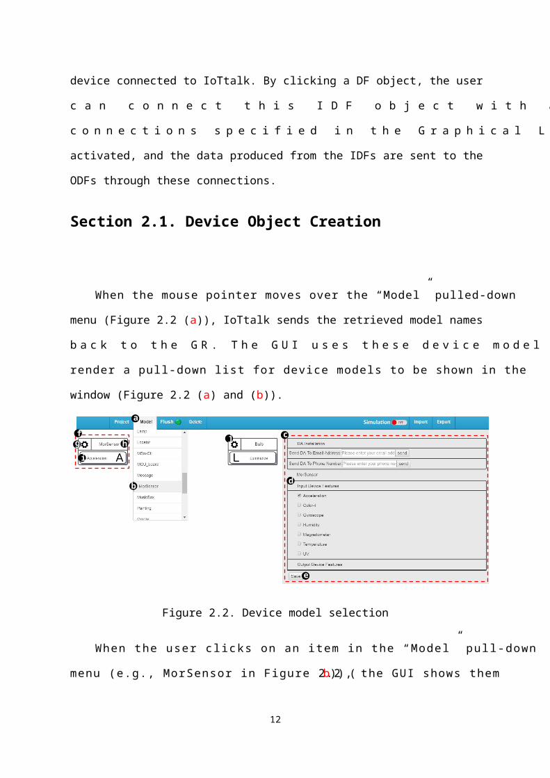
When the mouse pointer moves over the “Model” pulled-down menu (Figure 2.2 (a)),
IoTtalk sends the retrieved model names back to the GR. The GUI uses these device model
names to render a pull-down list for device models to be shown in the window (Figure 2.2 (a)
and (b)).
a
b
c
d
e
fg h
i
j
Figure 2.2. Device model selection
When the user clicks on an item in the “Model” pull-down menu (e.g., MorSensor in
Figure 2.2 (b)), the GUI shows them in the Management Window (Figure 2.2 (c)). In Figure
1.1, D1 (a MorSensor device) has two IDFs (i.e., Acceleration and Temperature). The GUI
renders the IDF/ODF Selection module to list all device features in the Management Window
(Figure 2.2 (d); note that in this example, MorSensor does not have any output device
features).
9

For the IoT devices involved in a project, not all device features of these IoT devices are
used. The user can select the needed device features from the device model for connections.
After the user has “checked” the desired device features (e.g., the graphical check box for
Acceleration in Figure 2.2 (d) is selected) and clicked the “Save” button (Figure 2.2 (e)),
which results in creation of a device object drawn in the Graphical Layout Window (Figure
2.2 (f)). As mentioned previously, the device object consists of a device setting object (Figure
2.2 (g)), a device model name object “MorSensor” (Figure 2.2 (h)) and one or more device
feature (DF) objects (Figure 2.2 (i)).
If the created device object has only one device feature (an IDF or an ODF), for
example, the Bulb only has the Luminance ODF, the GUI directly plots the device object
(Figure 2.2 (j)) in the Graphical Layout Window without asking the user to perform device
feature selection.
Section 2.2. GUI Operations on Device Objects
In this section, we describe how to download the DA code to a mobile phone, set up the
device objects and mount IoT devices on these device objects. Then we show how to establish
the connections among them and manage the corresponding DF functions.
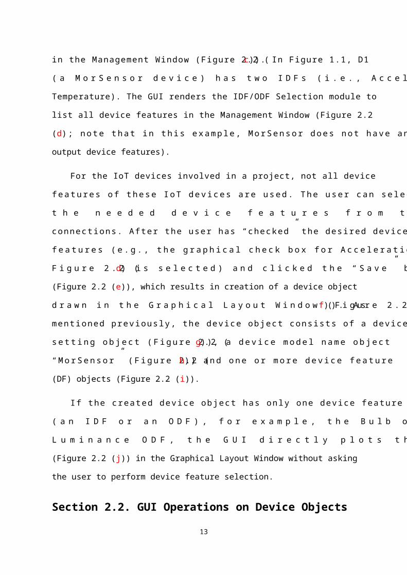
When the user clicks a device setting object (Figure 2.3 (a)), the GUI shows the
corresponding DF Selection module in the Management Window. Specifically, the GUI
retrieves the device object information (e.g., the possible DFs of MorSensor are
“Acceleration” and “Temperature”, and the Acceleration DF is selected in Figure 2.3). Then
the GUI illustrates the Device module (Figure 2.3 (b)) in the Management Window.
10
a b
c
d
e
f
g h
i
j
Figure 2.3. Device object setting
2.2.1. Device Application Installation
The Device module provides two input boxes (Figure 2.3 (c) and (d)) to send the
download hyperlink of the device model’s device application (DA) program to a mobile
phone through email or short message, respectively.
In Figure 1.3, an IoT device connects to IoTtalk through a mobile phone. To correctly
connect the IoT device to EasyConnet, the mobile phone must be installed the DA for this IoT
device. If the user inputs the email address in the Email input box (Figure 2.3 (c)), the IoTtalk
will send a message to that email account. The message body includes a download hyperlink
for the DA. When the user reads the email and clicks the download hyperlink through a
mobile phone, the DA will be automatically installed in that mobile phone. Similarly, the
above DA installation procedure can be executed through Short Message Service (SMS) by
filling the phone number in the SMS input box (Figure 2.3 (d)). When the user clicks the
“Send” button (Figure 2.3 (e) or (f)), IoTtalk sends a hyperlink of the DA code to the user by
email or SMS. The DA is installed automatically in a mobile phone when the user clicks this
link on that mobile phone.
11
2.2.2. Device Object Setting and Binding
Through the settings of the Device module, the user can manipulate a device with the
operations such as changing the selected device features or deleting the device object.
After the user has selected the device features and clicks the “Save” button (Figure 2.3
(g)), IoTtalk updates the device object information. Then the GUI illustrates the modified
device object in the Graphical Layout Window.
When the user clicks the “Delete” button (Figure 2.3 (h)), a dialog box pops up for the
user to reconfirm the deletion (Figure 2.3 (i)). After the user has clicked the “OK” button
(Figure 2.3 (j)), the IoTtalk deletes the information related to the device object from the DB
and the GUI removes the device object from the Graphical Layout Window.
When a device object is created, its name object shows the device model name (e.g.,
MorSensor in Figure 2.3 (a)). When the user clicks the name object, the GUI obtains all
registered devices of this device model from the DB. Suppose that several devices (e.g., My
MorSensor and My MorSensor2) of the same device model have registered to IoTtalk. For
each of the registered IoT devices, the GUI renders it as an item of the “Registered Device”
list in the Management Window (Figure 2.4 (a)).
bac
Figure 2.4. Device to device object binding
After the user has selected the device in the “Registered Device” list (e.g., My
MorSensor in Figure 2.4 (b)), IoTtalk binds the real device to the device object. Then the GUI
12
replaces the device model name (e.g., MorSensor) of the name object with the device name
(e.g., My MorSensor) highlighted with the blue color (Figure 2.4 (c)), which indicates that
this device object has been bound to a real device. If there is only one device in the
“Registered Device” list, the GUI replaces the device model name with the device name
without the need of the selection step (i.e., Figure 2.4 (a) is not shown).
To unbind a device, the user clicks the device name object (e.g. My MorSensor in
Figure 2.4 (c)). IoTtalk unbinds the device from the device object and the GUI replaces, for
example, “My MorSensor” by “MorSensor” in Figure 2.4.
2.2.3. Operations on Device Feature Connection
In IoTtalk, an IDF is connected to an ODF through a small circle called join object in
the Graphical Layout Window. In Figure 2.5, the Acceleration IDF object (Figure 2.5 (a)) is
connected to the join object (Figure 2.5 (b)) by a line segment, and the Luminance ODF
object (Figure 2.5 (c)) is also connected to the join object by another line segment. The two
links connecting an IDF and an ODF through the join circle (e.g., (a)-(b)-(c) in Figure 2.5)
define a data path. If a connection involves only one IDF, it is called a single join. If a
connection involves multiple IDFs, it is called a multiple join. For multiple IDFs connected to
a join point, IoTtalk provides the join functions for these IDFs to affect ODFs. For multiple
ODFs connected to a join point, the effects of the IDFs on all ODFs are the same. Therefore,
even if multiple ODFs are connected to a join point, it is still called a single join if only one
IDF is connected to this join point. This subsection elaborates on single join. Details of
multiple join will be discussed in the next subsection.
13
e
f
g
a
d
cb
Figure 2.5. Connection creation
We describe connection creation by using the example in Figure 2.5. By clicking the
Acceleration IDF object (Figure 2.5 (a)) and then the Luminance ODF object (Figure 2.5 (c)),
or in the reverse order, IoTtalk creates a connection. A connection includes several line
segments and a join object where the line segments meet. This connection is automatically
assigned a default name “Join 1” (Figure 2.5 (d)). Note that “Join K” represents the K-th
connection created in the project. This name can be modified by the user later. The connection
is implemented by a network application that is a Python program. After the IoTtalk has
stored the connection in the DB, the GUI draws the input box for the connection name (Figure
2.5 (e)), the IDF module (Figure 2.5 (f)), and the ODF module (Figure 2.5 (g)) in the
Management Window and highlights the connection object with the red color, which means
that the parameters of this connection object can be set up through the IDF and the ODF
modules in the Management Window.
The input and output device features are connected through the setups of the IDF
module (Figure 2.6 (a)) and the ODF module (Figure 2.6 (b)). The IDF module is a table that
lists the DF-parameters (x1, x2,…, xn) of an IDF. The (Sample) “Type” pull-down menu
(Figure 2.6 (c)) allows the user to specify the sample type of x i. Let xi(j) be the j-th xi datum
of the Acceleration IDF. When IoTtalk receives xi(j), the sample type of DF-parameter xi can
be sample (i.e., the value xi(j)) or variant (i.e., the difference xi(j)−¿xi(j-1)). IoTtalk provides
some DF functions (e.g., min, max, scalar and so on) that take the DF-parameters as inputs.
14

The user clicks to select a DF function in the “Function” pull-down menu (Figure 2.6 (d)).
The user can also select “add new function” (Figure 2.6 (e)) to create a new DF function or
select “disabled” so that no function is applied. If the user disables the DF function, the IDF-
parameters (x1,…, xn) will be passed to the next stage (e.g., the ODF module) directly. How to
create a DF function will be described in Section 2.2.5. In Figure 2.6 (c), the variant type is
selected for x1, x2 and x3 to compute the variation of acceleration. Then the scalar function
(Figure 2.6 (d)) is selected to transfer the IDF-parameter values (x1, x2, x3) to their scalar
value. This scalar value is automatically normalized in the range [0,1].
b
c d
ef
a
g
Figure 2.6. The IDF and the ODF modules in the Management Window
In the ODF module, the “Function” pull-down menu (Figure 2.6 (f)) allows the user to
select a DF function for each of the k ODF-parameters (y1,…, yi,…, yk). Since the ODF
function is disabled in Figure 2.6 (f), the input from the previous stage (e.g., the IDF module)
is assigned to yi directly. Before yi is received by the real output device, it may be scaled
within a range. By setting up the IDF and the ODF modules, the Acceleration IDF of the
MorSensor is mapped to the Luminance ODF of the Bulb.
To save a connection configuration in the DB, the user clicks the “Save” button (Figure
2.6 (g)). In this operation, the IoTtalk collects the IDF module settings (e.g., sample type and
IDF function) and the ODF module settings (e.g., ODF function), and stores the connection
15

configuration in the DB. After saving, for example, the device “My MorSensor” and the
device “My Bulb” in Figure 2.3 can interact through the connection configuration.
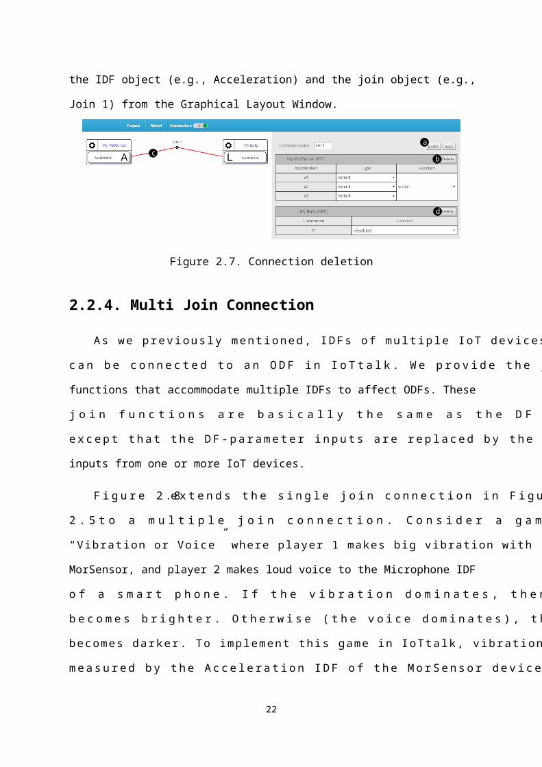
A connection can be “completely” deleted or “partially” deleted. If all line segments of
the connection are removed, it is a complete deletion. If one or more (but not all) line
segments are removed, it is a partial deletion. Therefore, there are two kinds of “Delete”
buttons. For the “Delete” button placed outside the IDF/ODF modules (Figure 2.7 (a)), it is
used for complete deletion. If a “Delete” button is placed inside the IDF/ODF module, it is
used to remove the line segment corresponding to the specific IDF/ODF module (Figure 2.7
(b) and (d)). When the user clicks the complete “Delete” button, IoTtalk completely deletes
the connection information from the DB, and the network application is removed. Finally, the
GUI removes the connection object from the Graphical Layout Window. To delete a specific
line segment of a connection, the user clicks the “Delete” button of the DF module
corresponding to that line segment. For example, when the user clicks the “Delete” button in
the IDF module (Figure 2.7 (b)), IoTtalk only deletes this specific line segment. Then the GUI
removes the line segment (Figure 2.7 (c)) between the IDF object (e.g., Acceleration) and the
join object (e.g., Join 1) from the Graphical Layout Window.
ca
b
d
Figure 2.7. Connection deletion
2.2.4. Multi Join Connection
16

As we previously mentioned, IDFs of multiple IoT devices can be connected to an ODF
in IoTtalk. We provide the join functions that accommodate multiple IDFs to affect ODFs.
These join functions are basically the same as the DF functions except that the DF-parameter
inputs are replaced by the IDF inputs from one or more IoT devices.
Figure 2.8 extends the single join connection in Figure 2.5 to a multiple join connection.
Consider a game called “Vibration or Voice” where player 1 makes big vibration with
MorSensor, and player 2 makes loud voice to the Microphone IDF of a smart phone. If the
vibration dominates, then a bulb becomes brighter. Otherwise (the voice dominates), the bulb
becomes darker. To implement this game in IoTtalk, vibration measured by the Acceleration
IDF of the MorSensor device is used as player 1’s input, and voice received by the
Microphone of the smart phone is used as player 2’s input. Luminance of the bulb is the
output of this game. “Does vibration dominate voice” is a join function “larger than” (z1>z2?)
that compares the normalized Acceleration value (z1) with the normalized Microphone value
(z2). If z1>z2, then the result zF=1. Otherwise (z1<z2), the result zF=0. In the Luminance ODF
module, the function Increment(zF) is selected, which increments the luminance of the bulb if
zF=1, and decrements the luminance if zF=0. To implement this game, we extend “Join 1” in
Figure 2.5 by adding a new device object (Figure 2.8 (a)) and a line segment (Figure 2.8 (b))
as follows: the user clicks the DF object “Microphone” (Figure 2.8 (c)) and the join object
“Join 1” (Figure 2.8 (d)) to create a new line segment.
a b
c
d
Figure 2.8. Adding a new device object and a new line segment
17

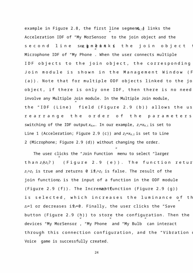
The outputs of M IDFs linked to the join object are (xN,1, …, xN,m, …, xN,M), where xN,m is
the IDF output for the m-th line segment. (The subscript notation N in xN,m means that this
value has been normalized between 0 and 1) These outputs become the inputs z1, z2, …, zM of
a join function. For the example in Figure 2.8, the first line segment (xN,1) links the
Acceleration IDF of “My MorSensor” to the join object and the second line segment (xN,2)
links the join object to the Microphone IDF of “My Phone”. When the user connects multiple
IDF objects to the join object, the corresponding Multiple Join module is shown in the
Management Window (Figure 2.9 (a)). Note that for multiple ODF objects linked to the join
object, if there is only one IDF, then there is no need to involve any Multiple Join module. In
the Multiple Join module, the “IDF (Line)” field (Figure 2.9 (b)) allows the user to rearrange
the order of the parameters; i.e., it allows switching of the IDF output xN,m. In our example,
z1=xN,1 is set to Line 1 (Acceleration; Figure 2.9 (c)) and z2=xN,2 is set to Line 2 (Microphone;
Figure 2.9 (d)) without changing the order.
The user clicks the “Join Function” menu to select “larger than (z1>z2?)” (Figure 2.9 (e)).
The function returns 1 if z1>z2 is true and returns 0 if z1>z2 is false. The result of the join
function zF is the input of a function in the ODF module (Figure 2.9 (f)). The Increment(zF)
function (Figure 2.9 (g)) is selected, which increases the luminance of the bulb if zF=1 or
decreases if zF=0. Finally, the user clicks the “Save” button (Figure 2.9 (h)) to store the
configuration. Then the devices “My MorSensor”, “My Phone” and “My Bulb” can interact
through this connection configuration, and the “Vibration or Voice” game is successfully
created.
18

a
f
b
cd e
g
h
i
Figure 2.9. Multiple Join module
2.2.5. Function Management Module
IoTtalk utilizes DF functions to manipulate the data transmitted between device features.
A DF function transforms the parameter inputs of an IDF to a value. For example, the scalar
function transfers the x-axis, the y-axis and the z-axis values (x1, x2, x3) of Acceleration into a
scalar value
Scalar ( x1, x2, x3 )=√ x12+x2
2+x32
These DF functions are collected in the Global Function List stored in the DB. Same
functions can be reused for different IDFs. For example, the Gyroscope IDF can use the same
scalar function to transfer its x-axis, y-axis, and z-axis values into the scalar value.
When the user selects the “add new function” in the “Function” pull-down menu of the
IDF/ODF module (e.g., Figure 2.9 (i)), IoTtalk obtains the DF function list from the DB. The
19

GUI hides the IDF/ODF modules and shows the Function Management module (Figure 2.10)
in the Management Window. To exit function management, the user clicks the “Close” button
(Figure 2.10 (c)), and the GUI redraws the IDF/ODF modules in the Management Window.
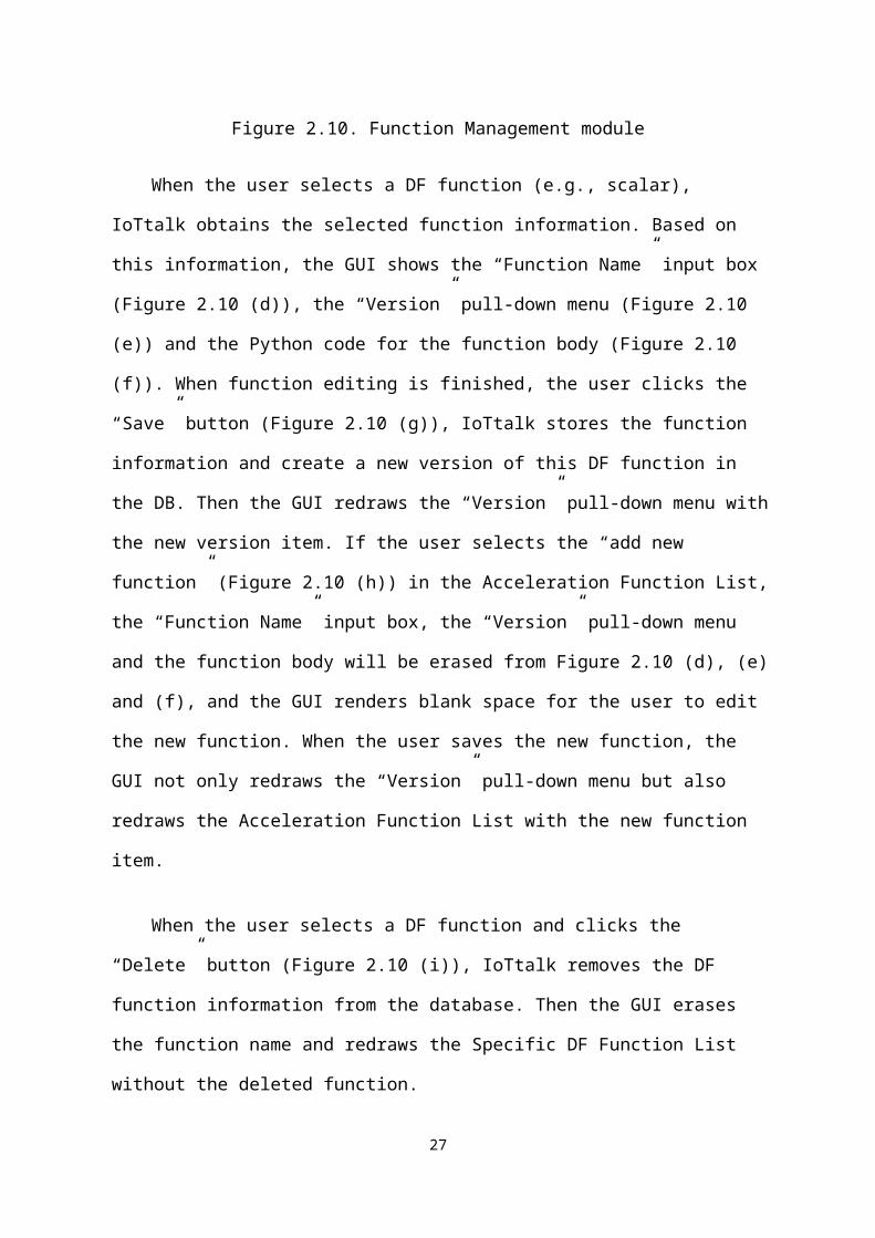
In the Function Management module, all DF functions are listed in the Global Function
List (Figure 2.10 (a)) and are stored in the Function Table of the DB. The DF functions for a
specific device feature (e.g., Acceleration) are listed in the Specific DF Function List (e.g., the
Acceleration Function List in Figure 2.10 (b)). This Specific DF Function List is stored in the
FunctionSDF table of the DB.
a b
def
gi
hj
k
c
Figure 2.10. Function Management module
When the user selects a DF function (e.g., scalar), IoTtalk obtains the selected function
information. Based on this information, the GUI shows the “Function Name” input box
(Figure 2.10 (d)), the “Version” pull-down menu (Figure 2.10 (e)) and the Python code for the
function body (Figure 2.10 (f)). When function editing is finished, the user clicks the “Save”
button (Figure 2.10 (g)), IoTtalk stores the function information and create a new version of
this DF function in the DB. Then the GUI redraws the “Version” pull-down menu with the
new version item. If the user selects the “add new function” (Figure 2.10 (h)) in the
Acceleration Function List, the “Function Name” input box, the “Version” pull-down menu
20

and the function body will be erased from Figure 2.10 (d), (e) and (f), and the GUI renders
blank space for the user to edit the new function. When the user saves the new function, the
GUI not only redraws the “Version” pull-down menu but also redraws the Acceleration
Function List with the new function item.
When the user selects a DF function and clicks the “Delete” button (Figure 2.10 (i)),
IoTtalk removes the DF function information from the database. Then the GUI erases the
function name and redraws the Specific DF Function List without the deleted function.
The functions for a DF can be organized as follows. The user clicks the “>>>” button
(Figure 2.10 (j)) to move a selected DF function from the Global Function List to the Specific
DF Function List (e.g., Acceleration Function List in Figure 2.10 (b)). To do so, IoTtalk
updates the function information in the DB, and the GUI redraws the Specific DF Function
List to include the selected function as an item in this list. Similar to the operation “>>>”, if
the user clicks the “<<<” button (Figure 2.10 (k)), IoTtalk moves the function from the
Specific DF Function List to the Global Function List.
Section 2.3. Device Feature and Model Management
IoTtalk provides the Device Feature and Model Management Window (Figure 2.11) to
create and manage the device features and the device models. This window includes a
“Device Feature/Device Model” (DF/DM) toggle button (Figure 2.11 (a)), a DF category bar
(Figure 2.11 (b)), the Device Feature Window (Figure 2.11 (c)) and Device Model Window
(Figure 2.11 (d)). When the “Device Feature” mode is selected in the toggle button (Figure
2.11 (a)), the Device Feature Window is activated, and the user can edit a new or an existing
device feature. On the other hand, when the “Device Model” mode is selected through the
21
toggle button, the Device Model Window pops up to allow the user to create and edit the
device models. The DF category bar lists all DF categories which can be Sight, Touch,
Echolocation, Hearing, Temperature, Motion, Chemoreceptor, Kinesthetic and
Magnetoception. The new IoTtalk version will reduce the DF categories to Sight, Hearing,
Feeling, Motion and Other.
d
a b
c
Motion
Motion
Figure 2.11. Device Feature and Model Management Window
2.3.1. Device Feature Management
To access the Device Feature Window, the user toggles the “DF/DM” button to the
“Device Feature” mode.
After the “Device Feature” mode is selected, the user clicks a DF category (e.g., Sight;
Figure 2.12 (a)) in the DF category bar. The GUI displays two radio buttons for IDF/ODF
type selection (Figure 2.12 (b)), and shows the selected DF category (Figure 2.12 (c)). The
IDF type is automatically selected as the default type, and IoTtalk obtains all DFs for the
selected DF category and DF type (Figure 2.12 (d)). The first item of the list is “add new DF”,
which can be clicked to create a new DF. The details are given in the next subsection. If the
22

user presses the ODF radio button (Figure 2.12 (b)), all IDFs in the “DF Name” list (Figure
2.12 (d)) are replaced by all ODFs of the selected category.
a
bcd
Sight
DF
CameraCamera
Color sensor
Figure 2.12. Device Feature Window
To create a new device feature, the user selects the “add new DF” in the “DF Name” list
(Figure 2.12 (d)), and the GUI pops up the DF Parameter module (Figure 2.13 (a)) in the
Device Feature Window. The rows of the DF Parameter module are created based on the
number of the DF-parameters (Figure 2.13 (b)). The default DF-parameter number is one. For
each of the DF-parameters, the DF Parameter module includes the Type (i.e., the data types
such as float, string and so on; see Figure 2.13 (c)), the Min (minimal) and Max (maximal)
values (Figure 2.13 (d)) and the Unit (e.g., cm, m/s2 and so on; Figure 2.13 (e)). For an IDF,
the Min/Max values are automatically assigned and the user does not need to fill these fields.
For an ODF, if the Min/Max fields are not filled, the ODF-parameters take arbitrary values
without range limits. The user edits them according to the characteristics of the ODF provided
in the manufacture’s data sheet. For example, the luminance value of the Bulb (D3 in Figure
1.1) has the range [0, 500]. When the user clicks the “Save” button (Figure 2.13 (f)), the GUI
pops a dialog box for the user to input the name of the new device feature (Figure 2.13 (g)).
Then IoTtalk stores device feature information into the DB. We note that the “Type” field
23
(Figure 2.13 (c)) refers to data type, which is different from the “Type” field for the sample
type in the IDF module in the Management Window (Figure 2.6 (c)).
bc d e
fg
a
Motion
Figure 2.13. Device feature creation
From the “DF Name” list, the user selects and edits an existing DF (e.g., Acceleration;
see Figure 2.14 (a)). If the user modifies the DF-parameter number (Figure 2.14 (b)), the DF
Parameter module will be redrawn based on the new number. Then the user can edit the data
type, the Min/Max values and the unit of each DF-parameter. After the user has completed
editing the device feature and clicks the “Save” button (Figure 2.14 (c)), a dialog box pops up
for the user to reconfirm the modifications (Figure 2.14 (d)). The device feature name is
shown in this dialog box, which allows the user to rename the modified device feature by a
new one. When the user clicks the “OK” button (Figure 2.14 (e)) of the dialog, IoTtalk stores
the information in the DB. When the user clicks the “Delete” button (Figure 2.14 (f)), IoTtalk
removes the device feature from the DB.
24

bc d e
fg
a
Motion
Figure 2.14. Device feature modification (*figure is replaced by figure 6.4 easyplug-In paper)
2.3.2. Device Model Management
To manage the device model, the user toggles the “DF/DM” mode to “Device Model”
(Figure 2.15 (a)). Then the Device Model Window is popped up (Figure 2.15 (b)) together
with the Device Feature Window (Figure 2.15 (c)). The Device Model Window shows the
“DM Name” pull-down menu (Figure 2.15 (d)) which allows the user to select a device
model. The first item in the list is “add new DM”. This item can be clicked to create a new
model. The Device Feature Window is also shown in the “Device Model” mode for the user’s
benefit: the user may need to know the details of a specific device feature when he/she is
configuring a device model.
a
cb
d
Figure 2.15. Device Model Window (*Motion!)
25

To create a new device model, the user selects the “add new DM” in the “DM Name”
pull-down menu (Figure 2.15 (d)), and the GUI pops up the DF module (Figure 2.16 (a)) and
the “Add/Delete DF” module (Figure 2.16 (b)) in the Device Model Window. The DF module
lists the DFs of the device model. For a new model, the DF module is empty initially. The
user can add a DF to this device model through the “Add/Delete DF” module. The operation
for adding a DF is described as follow. The user first selects a category for device features in
the DF category bar and selects the DF type from one of the two radio buttons in the
“Add/Delete DF” module (e.g., IDF is selected in Figure 2.16 (c)). Then the “Add/Delete DF”
module shows all DFs (Figure 2.16 (d)) of the selected DF type for the DF category (Figure
2.16 (e)). When the user selects a DF in the “Add/Delete DF” module, the DF is automatically
displayed in the DF module (Figure 2.16 (a)). After the user has selected all desired DFs for
the device model and clicks the “Save” button (Figure 2.16 (f)), the GUI pops a dialog box for
the user to input the name of the new device model (Figure 2.16 (g)) and IoTtalk creates the
new device model in the DB.
f
g
b c e
a
d
Figure 2.16. Device model creation
To configure an existing device model, the user selects that device model (e.g.,
Smartphone; Figure 2.17 (a)) in the “DM Name” pull-down menu. IoTtalk retrieves the DFs
26
of the device model from the DB and the GUI pops up the DF module (Figure 2.17 (b)) and
the “Add/Delete DF” module (Figure 2.17 (c)).
To obtain more details of a specific DF, the user moves the mouse pointer over the DF
name in either the DF module or the “Add/Delete DF” module (e.g., Acceleration; see Figure
2.17 (d)). IoTtalk obtains the details of the selected device feature and the GUI shows them in
the Device Feature Window (Figure 2.17 (e)). In this way, the user can conveniently
investigate the details of a DF selected in the Device Model Window.
If the user wants to delete a device feature (e.g., Microphone) from the device model,
he/she clicks the DF item in the DF module (Figure 2.17 (f)), and this device feature is shown
in the “Add/Delete DF” module automatically. Then the user can unselect the device feature
in the “Add/Delete DF” module (Figure 2.17 (g)) to remove it from the device model.
e
f
h k
d
g
i
j
c
a
b
Figure 2.17. Device model modification (*Motion!)
After the user has completed configuring the device model and clicks the “Save” button
(Figure 2.17 (h)), a dialog pops up for the user to reconfirm the modifications (Figure 2.17
(i)). The device model name is shown in this dialog, which allows the user to rename the
modified device model by a new one. When the user clicks the “OK” button (Figure 2.17 (j))
of the dialog, IoTtalk stores the information of the specific device model in the DB. On the
other hand, when the user clicks the “Delete” button (Figure 2.17 (k)), IoTtalk removes the
27
device model from the DB.
28