liquefaction resistance and post...
TRANSCRIPT
LIQUEFACTION RESISTANCE AND POST-LIQUEFACTION RESPONSE OF SOILS FOR SEISMIC DESIGN OF BUILDINGS IN GREATER VANCOUVER Peter Byrne, Dept. of Civil Engineering, University of British Columbia, Vancouver, B.C., Canada Dharma Wijewickreme, Dept. of Civil Engineering, University of British Columbia, Vancouver, B.C., Canada ABSTRACT Guidelines are recommended for determining the required geotechnical capacities (resistances) for the seismic design of foundations in Greater Vancouver, British Columbia, Canada, to account for the change in seismic design philosophy in the new version of the National Building Code of Canada (NBCC2005). The focus here is on assessment of liquefaction potential and post-cyclic response of soils to assist the prediction of earthquake-induced geotechnical hazard (i.e., ground deformations - flow slides, bearing failures, or limited ground movements). Specific guidelines have been developed to assess the cyclic resistance ratio (CRR), post-cyclic residual shear strength, and post-cyclic consolidation settlements with separate treatment of coarse-grained soils and fine-grained soils. RÉSUMÉ Des directives sont recommandées pour déterminer les capacités (résistances) géotechniques exigées pour la conception séismique des fondations du Grand Vancouver, en Colombie Britannique, Canada, pour expliquer le changement de la philosophie de conception séismique dans la nouvelle version du code de Bâtiment National du Canada (NBCC 2005). Le focus ici est sur l'évaluation du potentiel de liquéfaction et la réponse post-cyclique des sols pour aider à prédire le risque géotechnique induit par des tremblement de terre (i.e., déformations au sol – écoulement de talus, rupture portante, ou des mouvements au sol limités). Des directives spécifiques ont été développées pour évaluer le rapport cyclique de résistance (CRR), la résistance au cisaillement résiduelle post-cyclique, et les tassements post-cycliques de consolidation avec le traitement séparé des sols à gros et fins grains. 1. INTRODUCTION The new version of the National Building Code of Canada (NBCC 2005) has been adopted, replacing its predecessor NBCC (1995). One of the main changes imposed by the new building code is the substantial decrease in the annual risk level (or increase in the return period) associated with the ground motions required for the design of buildings. The seismic hazard in the NBCC (1995) is defined with respect to a 10% probability of exceedance in 50 years (i.e., return period of 475 years), whereas that in the new NBCC (2005) is stipulated to be a 2% probability of exceedance in 50 years (i.e., return period of 2,475 years). Furthermore, the seismic design philosophy has changed to collapse prevention from what used to be moderate damage and life-safety in the old code. Of particular interest to the geotechnical engineers is the impact of the high-intensity design ground motions prescribed by the new code on the assessment of soil liquefaction, computation of ground/foundation movements, and determination of any needed remedial measures. In 1991, a task force consisting of a group of geotechnical and structural engineers in the Greater Vancouver area of British Columbia, Canada, produced a report entitled “Earthquake Design in the Fraser Delta” (Task Force Report, 1991). This report was intended to provide general design guidelines for engineers involved in the seismic design of foundations for buildings in the Fraser Delta where liquefaction is a concern. It is now recognized that, with the introduction of the new version of
the building code, there is a need to update these guidelines and establish a uniform approach for seismic design in the Greater Vancouver area. A task force was established in November 2004 in this regard, and new design guidelines have been developed taking into consideration the longer return period ground motions and the change in seismic design philosophy [i.e., Task Force Report (In Press) for seismic geotechnical design in the Greater Vancouver area]. This paper is intended to present the recommended guidelines by the above task force for determining the required geotechnical capacities (resistances) for the seismic design of foundations in Greater Vancouver with respect to: (i) the assessment of liquefaction potential, and (ii) post-cyclic response of soils to assist in the prediction of earthquake-induced geotechnical hazard (i.e., ground deformations - flow slide, bearing failures, or limited ground movements). The seismic design process involves: (i) determination of the seismic demand (loading) at a given site [this in turn involves the design response spectra, representative earthquake magnitude(s), and appropriate time histories of acceleration or velocity on firm ground]; (ii) evaluation of liquefaction resistance and residual strength as discussed in this paper; (iii) analysis to evaluate ground and foundation liquefaction response, displacements in particular; and (iv) computation of allowable displacements, and design of remedial measures to
1267
Sea to Sky Geotechnique 2006
reduce predicted displacements to tolerable levels if required. The additional topics (i), (iii), and (iv) are discussed by Finn and Wightman (2006), Anderson (2006), and DeVall (2006) in companion papers to this conference special session, and also in the new task force report (Task Force Report In Press) for seismic geotechnical design in the Greater Vancouver area. 2. BACKGROUND Since 1991, there have been considerable advances in the methods used to assess soil liquefaction, as well as analysis techniques that can better predict movements associated with liquefied sites. Furthermore, there have been a number of earthquakes causing soil liquefaction and foundation damage, leading to a better understanding of the associated phenomena. However, there are many judgmental factors in assessing soil liquefaction, and its implications on safety, and there is a need for some consensus on these issues to reflect what will be the accepted state of practice when using the new NBCC (2005). The recent work reported in Youd et al. (2001), arising from the workshops sponsored by the National Center for Earthquake Engineering Research (NCEER), presently serves as the main guiding document to practitioners in geotechnical design. However, there are several areas in which no clear consensus position has been established with respect to the assessment of liquefaction resistance and post-cyclic response; this is particularly true on the treatment of silts and silty sands, and several alternate approaches are emerging and under discussion as noted by Boulanger and Idriss (2004). Seismic liquefaction refers to a sudden loss in shear stiffness and strength of soil due to cyclic loading effects of an earthquake. The loss arises from a tendency for soil to contract under cyclic loading, and if such contraction is prevented or curtailed by the presence of pore water that cannot escape, it leads to a rise in pore water pressure and a resulting drop in effective stress. If the effective stress drops to zero (100% pore water pressure rise), the shear strength and stiffness also drop to zero and the soil behaves as a heavy liquid. However, unless the soil is very loose, it will dilate and regain some shear stiffness and strength as it strains. The post-liquefaction shear strength is commonly referred to as the residual shear strength and may be 1 to 10 times lower than the static shear strength. If the residual shear strength is sufficient, it will prevent a bearing failure for level ground conditions, but still may result in excessive ground settlements. For sloping ground conditions, if the residual strength is sufficient, it will prevent a flow slide, but displacements commonly referred to as lateral spreading, could occur along with settlements. These ground or foundation movements may be excessive for functionality of the structure. In addition, even for level ground condition where there is no possibility of a flow slide and lateral movements may be tolerable, large
settlements may occur due to dissipation of excess pore water pressures during and after the period of strong ground shaking. Determination of appropriate site-specific engineering properties for the soil conditions at a site is a key aspect in evaluating the earthquake response. These properties are generally quantified based on in-situ penetration measurements and shear strength tests, as well as laboratory index and direct simple shear tests on representative soil samples. Understanding the geological processes leading to the formation of the soil deposit is important, and it can provide insight to the engineering properties and their variability. Post-glacial or Holocene soils of fluvial and alluvial depositional origin and loose man-made fill materials are highly vulnerable to soil liquefaction and form the class of soils for which the design guidelines given in this paper are applicable. Pre-glacial soils encountered in the Greater Vancouver region are generally dense and would have a low vulnerability to liquefaction under the seismic loading conditions described herein. There is some evidence that liquefaction resistance may improve with aging and over-consolidation (preloading). However, these effects are difficult to quantify and are usually not directly addressed in design procedures. 2.1 Assessment of Liquefaction and Prediction of
Earthquake-induced Geotechnical Hazard Liquefaction assessment and prediction of earthquake-induced geotechnical hazard involves addressing the following concerns:
• Will liquefaction be triggered in significant zones of the soil foundation for the design earthquake? and if so,
• Could a bearing failure or flow slide occur? and if not,
• Are the displacements tolerable?
These questions can be addressed from simplified or detailed analysis procedures. Simplified analysis of liquefaction triggering involves comparing the cyclic stress ratio (CSR) caused by the design earthquake with the cyclic resistance ratio (CRR) that the soil possesses mainly as a result of its density and stress conditions. If triggering of liquefaction is predicted in zones within the foundation soils, checking the possibility of a bearing failure or flow slide, or the estimation of displacements will require an understanding of the post-liquefaction stress-strain response of soils. The guidelines recommended by the task force for the determination of the liquefaction resistance and post-liquefaction stress-strain response are presented for coarse-grained and fine-grained soils in Sections 4 and 5, respectively. An overview of typical cyclic response of
1268
Sea to Sky Geotechnique 2006
soils that serves as a background for these recommendations is presented below in Section 3. 3. TYPICAL CYCLIC RESPONSE OF SOILS AND LIQUEFACTION Seismic loading subjects elements of the foundation soil to oscillating (or cyclic) shear stresses, typically denoted by the symbol τcyc. Laboratory and field experience indicate that it is the cyclic stress ratio (CSR), where CSR = τcyc/σ΄vo, and σ΄vo is the vertical effective stress prior to seismic loading that induces liquefaction and the development of large strains. The cyclic resistance ratio (CRR) is a measure of the soils ability to resist liquefaction and the development of large strains. CRR depends mainly on the soil type and density or state, and it can be obtained directly from tests on undisturbed samples of soil, or indirectly from field experience and in-situ testing at sites recently subjected to seismic loading. When CRR is obtained using laboratory testing, the common approach is to subject specimens of soil to cyclic shear loading using triaxial or direct simple shear devices. In laboratory cyclic shear testing, an equivalent uniform amplitude cyclic stress ratio is generally applied and the number of cycles to cause liquefaction (100% pore pressure rise or a specified strain) is recorded. Cyclic direct simple shear (DSS) tests are considered to be representative of field conditions during earthquake loading. While other advanced apparatus such as hollow cylinder torsional (HCT) shear device may be considered to simulate these loadings, they are less attractive because of their lack of availability, experimental complexities, and the associated high costs.
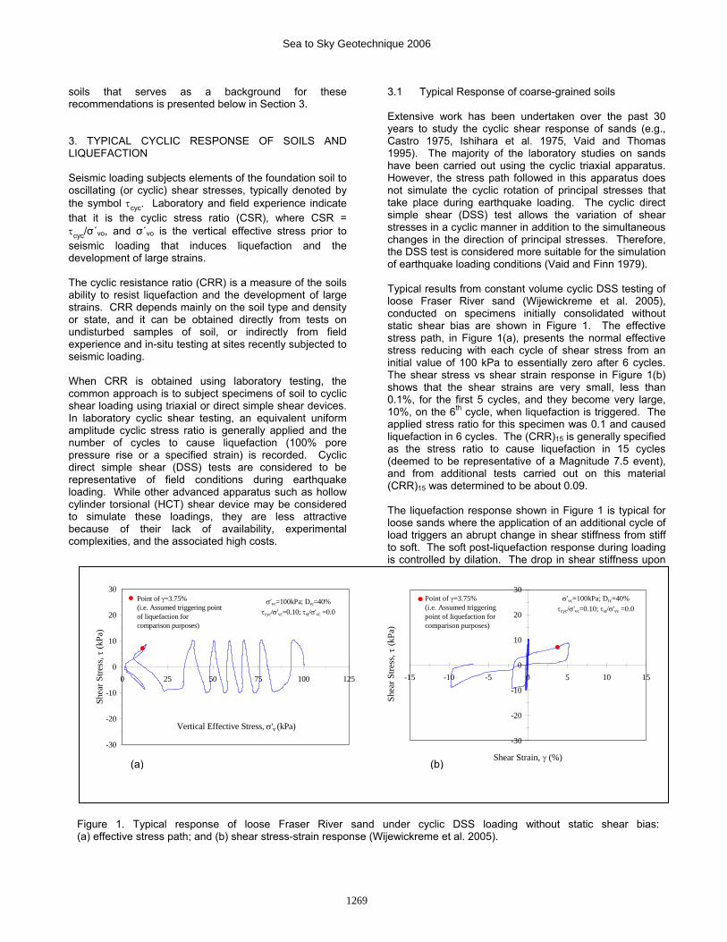
3.1 Typical Response of coarse-grained soils Extensive work has been undertaken over the past 30 years to study the cyclic shear response of sands (e.g., Castro 1975, Ishihara et al. 1975, Vaid and Thomas 1995). The majority of the laboratory studies on sands have been carried out using the cyclic triaxial apparatus. However, the stress path followed in this apparatus does not simulate the cyclic rotation of principal stresses that take place during earthquake loading. The cyclic direct simple shear (DSS) test allows the variation of shear stresses in a cyclic manner in addition to the simultaneous changes in the direction of principal stresses. Therefore, the DSS test is considered more suitable for the simulation of earthquake loading conditions (Vaid and Finn 1979). Typical results from constant volume cyclic DSS testing of loose Fraser River sand (Wijewickreme et al. 2005), conducted on specimens initially consolidated without static shear bias are shown in Figure 1. The effective stress path, in Figure 1(a), presents the normal effective stress reducing with each cycle of shear stress from an initial value of 100 kPa to essentially zero after 6 cycles. The shear stress vs shear strain response in Figure 1(b) shows that the shear strains are very small, less than 0.1%, for the first 5 cycles, and they become very large, 10%, on the 6th cycle, when liquefaction is triggered. The applied stress ratio for this specimen was 0.1 and caused liquefaction in 6 cycles. The (CRR)15 is generally specified as the stress ratio to cause liquefaction in 15 cycles (deemed to be representative of a Magnitude 7.5 event), and from additional tests carried out on this material (CRR)15 was determined to be about 0.09. The liquefaction response shown in Figure 1 is typical for loose sands where the application of an additional cycle of load triggers an abrupt change in shear stiffness from stiff to soft. The soft post-liquefaction response during loading is controlled by dilation. The drop in shear stiffness upon
-30
-20
-10
0
10
20
30
0 25 50 75 100 125
Vertical Effective Stress, σ'v (kPa)
Shea
r Stre
ss, τ
(kPa
)
σ'vc=100kPa; Drc=40%τcyc/σ'vc=0.10; τst/σ'vc =0.0
Point of γ=3.75%(i.e. Assumed triggering point of liquefaction for comparison purposes)
-30
-20
-10
0
10
20
30
-15 -10 -5 0 5 10 15
Shear Strain, γ (%)
Shea
r Stre
ss, τ
(kPa
)
σ'vc=100kPa; Drc=40%τcyc/σ'vc=0.10; τst/σ'vc =0.0
Point of γ=3.75%(i.e. Assumed triggering point of liquefaction for comparison purposes)
(b) (a)
Figure 1. Typical response of loose Fraser River sand under cyclic DSS loading without static shear bias:(a) effective stress path; and (b) shear stress-strain response (Wijewickreme et al. 2005).
1269
Sea to Sky Geotechnique 2006
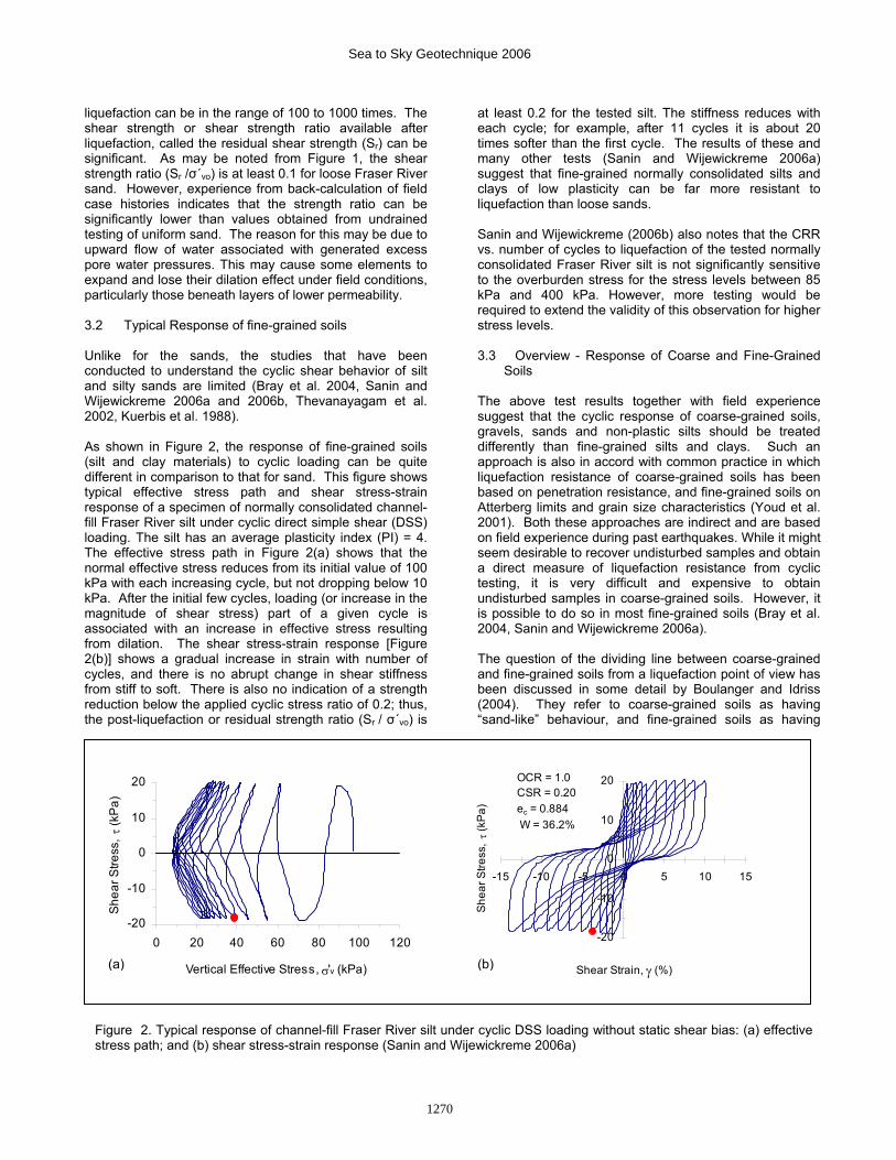
liquefaction can be in the range of 100 to 1000 times. The shear strength or shear strength ratio available after liquefaction, called the residual shear strength (Sr) can be significant. As may be noted from Figure 1, the shear strength ratio (Sr /σ΄vo) is at least 0.1 for loose Fraser River sand. However, experience from back-calculation of field case histories indicates that the strength ratio can be significantly lower than values obtained from undrained testing of uniform sand. The reason for this may be due to upward flow of water associated with generated excess pore water pressures. This may cause some elements to expand and lose their dilation effect under field conditions, particularly those beneath layers of lower permeability. 3.2 Typical Response of fine-grained soils Unlike for the sands, the studies that have been conducted to understand the cyclic shear behavior of silt and silty sands are limited (Bray et al. 2004, Sanin and Wijewickreme 2006a and 2006b, Thevanayagam et al. 2002, Kuerbis et al. 1988). As shown in Figure 2, the response of fine-grained soils (silt and clay materials) to cyclic loading can be quite different in comparison to that for sand. This figure shows typical effective stress path and shear stress-strain response of a specimen of normally consolidated channel-fill Fraser River silt under cyclic direct simple shear (DSS) loading. The silt has an average plasticity index (PI) = 4. The effective stress path in Figure 2(a) shows that the normal effective stress reduces from its initial value of 100 kPa with each increasing cycle, but not dropping below 10 kPa. After the initial few cycles, loading (or increase in the magnitude of shear stress) part of a given cycle is associated with an increase in effective stress resulting from dilation. The shear stress-strain response [Figure 2(b)] shows a gradual increase in strain with number of cycles, and there is no abrupt change in shear stiffness from stiff to soft. There is also no indication of a strength reduction below the applied cyclic stress ratio of 0.2; thus, the post-liquefaction or residual strength ratio (Sr / σ΄vo) is
at least 0.2 for the tested silt. The stiffness reduces with each cycle; for example, after 11 cycles it is about 20 times softer than the first cycle. The results of these and many other tests (Sanin and Wijewickreme 2006a) suggest that fine-grained normally consolidated silts and clays of low plasticity can be far more resistant to liquefaction than loose sands. Sanin and Wijewickreme (2006b) also notes that the CRR vs. number of cycles to liquefaction of the tested normally consolidated Fraser River silt is not significantly sensitive to the overburden stress for the stress levels between 85 kPa and 400 kPa. However, more testing would be required to extend the validity of this observation for higher stress levels. 3.3 Overview - Response of Coarse and Fine-Grained
Soils The above test results together with field experience suggest that the cyclic response of coarse-grained soils, gravels, sands and non-plastic silts should be treated differently than fine-grained silts and clays. Such an approach is also in accord with common practice in which liquefaction resistance of coarse-grained soils has been based on penetration resistance, and fine-grained soils on Atterberg limits and grain size characteristics (Youd et al. 2001). Both these approaches are indirect and are based on field experience during past earthquakes. While it might seem desirable to recover undisturbed samples and obtain a direct measure of liquefaction resistance from cyclic testing, it is very difficult and expensive to obtain undisturbed samples in coarse-grained soils. However, it is possible to do so in most fine-grained soils (Bray et al. 2004, Sanin and Wijewickreme 2006a). The question of the dividing line between coarse-grained and fine-grained soils from a liquefaction point of view has been discussed in some detail by Boulanger and Idriss (2004). They refer to coarse-grained soils as having “sand-like” behaviour, and fine-grained soils as having
-20
-10
0
10
20
-15 -10 -5 0 5 10 15
Shear Strain, γ (%)
She
ar S
tress
, τ
(kP
a)
OCR = 1.0 CSR = 0.20 ec = 0.884 W = 36.2%
-20
-10
0
10
20
0 20 40 60 80 100 120
Vertical Effective Stress, σ'v (kPa)
She
ar S
tress
, τ (k
Pa)
(a) (b)
Figure 2. Typical response of channel-fill Fraser River silt under cyclic DSS loading without static shear bias: (a) effective stress path; and (b) shear stress-strain response (Sanin and Wijewickreme 2006a)
1270
Sea to Sky Geotechnique 2006
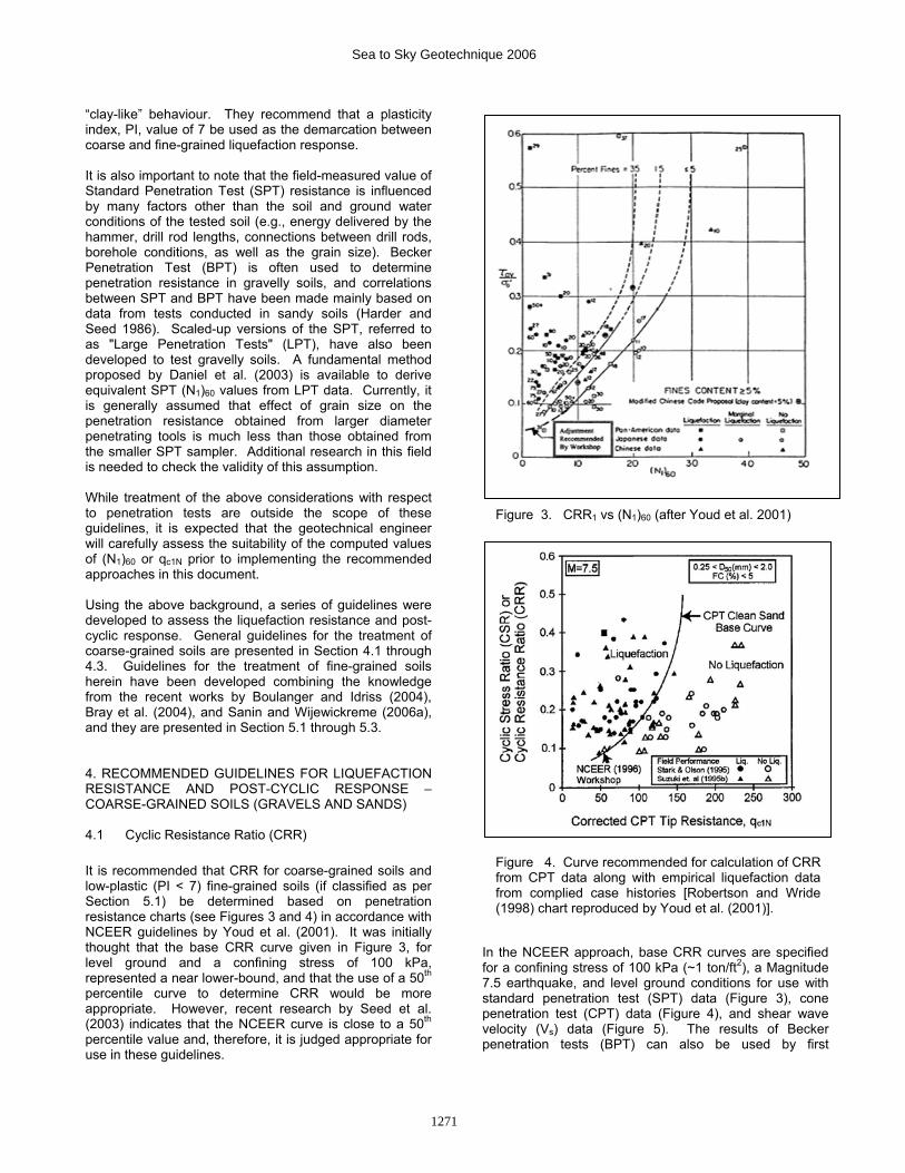
“clay-like” behaviour. They recommend that a plasticity index, PI, value of 7 be used as the demarcation between coarse and fine-grained liquefaction response. It is also important to note that the field-measured value of Standard Penetration Test (SPT) resistance is influenced by many factors other than the soil and ground water conditions of the tested soil (e.g., energy delivered by the hammer, drill rod lengths, connections between drill rods, borehole conditions, as well as the grain size). Becker Penetration Test (BPT) is often used to determine penetration resistance in gravelly soils, and correlations between SPT and BPT have been made mainly based on data from tests conducted in sandy soils (Harder and Seed 1986). Scaled-up versions of the SPT, referred to as "Large Penetration Tests" (LPT), have also been developed to test gravelly soils. A fundamental method proposed by Daniel et al. (2003) is available to derive equivalent SPT (N1)60 values from LPT data. Currently, it is generally assumed that effect of grain size on the penetration resistance obtained from larger diameter penetrating tools is much less than those obtained from the smaller SPT sampler. Additional research in this field is needed to check the validity of this assumption. While treatment of the above considerations with respect to penetration tests are outside the scope of these guidelines, it is expected that the geotechnical engineer will carefully assess the suitability of the computed values of (N1)60 or qc1N prior to implementing the recommended approaches in this document. Using the above background, a series of guidelines were developed to assess the liquefaction resistance and post-cyclic response. General guidelines for the treatment of coarse-grained soils are presented in Section 4.1 through 4.3. Guidelines for the treatment of fine-grained soils herein have been developed combining the knowledge from the recent works by Boulanger and Idriss (2004), Bray et al. (2004), and Sanin and Wijewickreme (2006a), and they are presented in Section 5.1 through 5.3. 4. RECOMMENDED GUIDELINES FOR LIQUEFACTION RESISTANCE AND POST-CYCLIC RESPONSE – COARSE-GRAINED SOILS (GRAVELS AND SANDS) 4.1 Cyclic Resistance Ratio (CRR) It is recommended that CRR for coarse-grained soils and low-plastic (PI < 7) fine-grained soils (if classified as per Section 5.1) be determined based on penetration resistance charts (see Figures 3 and 4) in accordance with NCEER guidelines by Youd et al. (2001). It was initially thought that the base CRR curve given in Figure 3, for level ground and a confining stress of 100 kPa, represented a near lower-bound, and that the use of a 50th percentile curve to determine CRR would be more appropriate. However, recent research by Seed et al. (2003) indicates that the NCEER curve is close to a 50th percentile value and, therefore, it is judged appropriate for use in these guidelines.
In the NCEER approach, base CRR curves are specified for a confining stress of 100 kPa (~1 ton/ft2), a Magnitude 7.5 earthquake, and level ground conditions for use with standard penetration test (SPT) data (Figure 3), cone penetration test (CPT) data (Figure 4), and shear wave velocity (Vs) data (Figure 5). The results of Becker penetration tests (BPT) can also be used by first
Figure 3. CRR1 vs (N1)60 (after Youd et al. 2001)
Figure 4. Curve recommended for calculation of CRR from CPT data along with empirical liquefaction data from complied case histories [Robertson and Wride (1998) chart reproduced by Youd et al. (2001)].
1271
Sea to Sky Geotechnique 2006
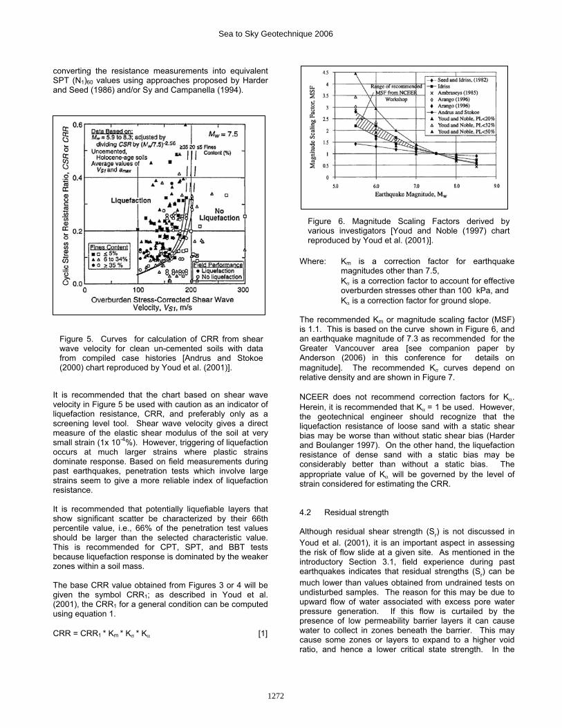
converting the resistance measurements into equivalent SPT (N1)60 values using approaches proposed by Harder and Seed (1986) and/or Sy and Campanella (1994).
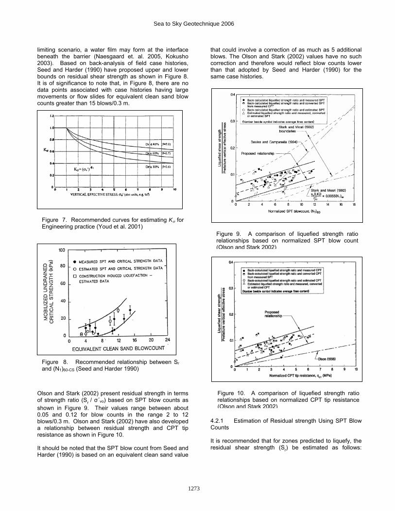
It is recommended that the chart based on shear wave velocity in Figure 5 be used with caution as an indicator of liquefaction resistance, CRR, and preferably only as a screening level tool. Shear wave velocity gives a direct measure of the elastic shear modulus of the soil at very small strain (1x 10⁻⁴%). However, triggering of liquefaction occurs at much larger strains where plastic strains dominate response. Based on field measurements during past earthquakes, penetration tests which involve large strains seem to give a more reliable index of liquefaction resistance. It is recommended that potentially liquefiable layers that show significant scatter be characterized by their 66th percentile value, i.e., 66% of the penetration test values should be larger than the selected characteristic value. This is recommended for CPT, SPT, and BBT tests because liquefaction response is dominated by the weaker zones within a soil mass. The base CRR value obtained from Figures 3 or 4 will be given the symbol CRR1; as described in Youd et al. (2001), the CRR1 for a general condition can be computed using equation 1. CRR = CRR1 * Km * Kσ * Kα [1]
Where: Km is a correction factor for earthquake magnitudes other than 7.5,
Kσ is a correction factor to account for effective overburden stresses other than 100 kPa, and
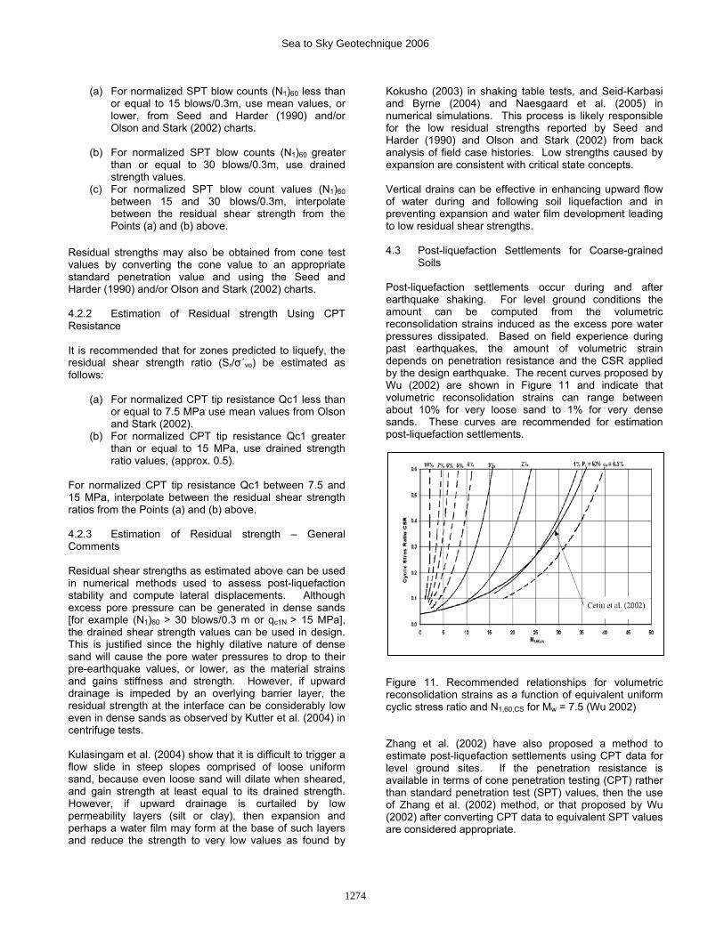
Kα is a correction factor for ground slope. The recommended Km or magnitude scaling factor (MSF) is 1.1. This is based on the curve shown in Figure 6, and an earthquake magnitude of 7.3 as recommended for the Greater Vancouver area [see companion paper by Anderson (2006) in this conference for details on magnitude]. The recommended Kσ curves depend on relative density and are shown in Figure 7. NCEER does not recommend correction factors for Kα. Herein, it is recommended that Kα = 1 be used. However, the geotechnical engineer should recognize that the liquefaction resistance of loose sand with a static shear bias may be worse than without static shear bias (Harder and Boulanger 1997). On the other hand, the liquefaction resistance of dense sand with a static bias may be considerably better than without a static bias. The appropriate value of Kα will be governed by the level of strain considered for estimating the CRR. 4.2 Residual strength Although residual shear strength (Sr) is not discussed in Youd et al. (2001), it is an important aspect in assessing the risk of flow slide at a given site. As mentioned in the introductory Section 3.1, field experience during past earthquakes indicates that residual strengths (Sr) can be much lower than values obtained from undrained tests on undisturbed samples. The reason for this may be due to upward flow of water associated with excess pore water pressure generation. If this flow is curtailed by the presence of low permeability barrier layers it can cause water to collect in zones beneath the barrier. This may cause some zones or layers to expand to a higher void ratio, and hence a lower critical state strength. In the
Figure 6. Magnitude Scaling Factors derived by various investigators [Youd and Noble (1997) chart reproduced by Youd et al. (2001)].
Figure 5. Curves for calculation of CRR from shear wave velocity for clean un-cemented soils with data from compiled case histories [Andrus and Stokoe (2000) chart reproduced by Youd et al. (2001)].
1272
Sea to Sky Geotechnique 2006
limiting scenario, a water film may form at the interface beneath the barrier (Naesgaard et. al. 2005, Kokusho 2003). Based on back-analysis of field case histories, Seed and Harder (1990) have proposed upper and lower bounds on residual shear strength as shown in Figure 8. It is of significance to note that, in Figure 8, there are no data points associated with case histories having large movements or flow slides for equivalent clean sand blow counts greater than 15 blows/0.3 m.
Olson and Stark (2002) present residual strength in terms of strength ratio (Sr / σ΄vo) based on SPT blow counts as shown in Figure 9. Their values range between about 0.05 and 0.12 for blow counts in the range 2 to 12 blows/0.3 m. Olson and Stark (2002) have also developed a relationship between residual strength and CPT tip resistance as shown in Figure 10. It should be noted that the SPT blow count from Seed and Harder (1990) is based on an equivalent clean sand value
that could involve a correction of as much as 5 additional blows. The Olson and Stark (2002) values have no such correction and therefore would reflect blow counts lower than that adopted by Seed and Harder (1990) for the same case histories.
4.2.1 Estimation of Residual strength Using SPT Blow Counts It is recommended that for zones predicted to liquefy, the residual shear strength (Sr) be estimated as follows:
Figure 9. A comparison of liquefied strength ratio relationships based on normalized SPT blow count (Olson and Stark 2002)
Figure 8. Recommended relationship between Sr and (N1)60-CS (Seed and Harder 1990)
Figure 10. A comparison of liquefied strength ratio relationships based on normalized CPT tip resistance (Olson and Stark 2002)
Figure 7. Recommended curves for estimating Kσ for Engineering practice (Youd et al. 2001)
1273
Sea to Sky Geotechnique 2006
(a) For normalized SPT blow counts (N1)60 less than or equal to 15 blows/0.3m, use mean values, or lower, from Seed and Harder (1990) and/or Olson and Stark (2002) charts.
(b) For normalized SPT blow counts (N1)60 greater
than or equal to 30 blows/0.3m, use drained strength values.
(c) For normalized SPT blow count values (N1)60 between 15 and 30 blows/0.3m, interpolate between the residual shear strength from the Points (a) and (b) above.
Residual strengths may also be obtained from cone test values by converting the cone value to an appropriate standard penetration value and using the Seed and Harder (1990) and/or Olson and Stark (2002) charts. 4.2.2 Estimation of Residual strength Using CPT Resistance It is recommended that for zones predicted to liquefy, the residual shear strength ratio (Sr/σ΄vo) be estimated as follows:
(a) For normalized CPT tip resistance Qc1 less than or equal to 7.5 MPa use mean values from Olson and Stark (2002).
(b) For normalized CPT tip resistance Qc1 greater than or equal to 15 MPa, use drained strength ratio values, (approx. 0.5).
For normalized CPT tip resistance Qc1 between 7.5 and 15 MPa, interpolate between the residual shear strength ratios from the Points (a) and (b) above. 4.2.3 Estimation of Residual strength – General Comments Residual shear strengths as estimated above can be used in numerical methods used to assess post-liquefaction stability and compute lateral displacements. Although excess pore pressure can be generated in dense sands [for example (N1)60 > 30 blows/0.3 m or qc1N > 15 MPa], the drained shear strength values can be used in design. This is justified since the highly dilative nature of dense sand will cause the pore water pressures to drop to their pre-earthquake values, or lower, as the material strains and gains stiffness and strength. However, if upward drainage is impeded by an overlying barrier layer, the residual strength at the interface can be considerably low even in dense sands as observed by Kutter et al. (2004) in centrifuge tests. Kulasingam et al. (2004) show that it is difficult to trigger a flow slide in steep slopes comprised of loose uniform sand, because even loose sand will dilate when sheared, and gain strength at least equal to its drained strength. However, if upward drainage is curtailed by low permeability layers (silt or clay), then expansion and perhaps a water film may form at the base of such layers and reduce the strength to very low values as found by
Kokusho (2003) in shaking table tests, and Seid-Karbasi and Byrne (2004) and Naesgaard et al. (2005) in numerical simulations. This process is likely responsible for the low residual strengths reported by Seed and Harder (1990) and Olson and Stark (2002) from back analysis of field case histories. Low strengths caused by expansion are consistent with critical state concepts. Vertical drains can be effective in enhancing upward flow of water during and following soil liquefaction and in preventing expansion and water film development leading to low residual shear strengths. 4.3 Post-liquefaction Settlements for Coarse-grained
Soils Post-liquefaction settlements occur during and after earthquake shaking. For level ground conditions the amount can be computed from the volumetric reconsolidation strains induced as the excess pore water pressures dissipated. Based on field experience during past earthquakes, the amount of volumetric strain depends on penetration resistance and the CSR applied by the design earthquake. The recent curves proposed by Wu (2002) are shown in Figure 11 and indicate that volumetric reconsolidation strains can range between about 10% for very loose sand to 1% for very dense sands. These curves are recommended for estimation post-liquefaction settlements.
Figure 11. Recommended relationships for volumetric reconsolidation strains as a function of equivalent uniform cyclic stress ratio and N1,60,CS for Mw = 7.5 (Wu 2002) Zhang et al. (2002) have also proposed a method to estimate post-liquefaction settlements using CPT data for level ground sites. If the penetration resistance is available in terms of cone penetration testing (CPT) rather than standard penetration test (SPT) values, then the use of Zhang et al. (2002) method, or that proposed by Wu (2002) after converting CPT data to equivalent SPT values are considered appropriate.
1274
Sea to Sky Geotechnique 2006
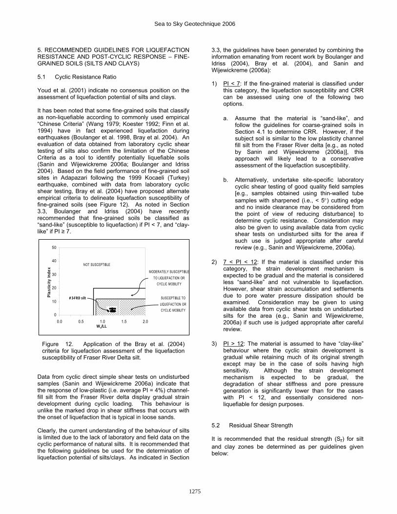
5. RECOMMENDED GUIDELINES FOR LIQUEFACTION RESISTANCE AND POST-CYCLIC RESPONSE – FINE-GRAINED SOILS (SILTS AND CLAYS) 5.1 Cyclic Resistance Ratio Youd et al. (2001) indicate no consensus position on the assessment of liquefaction potential of silts and clays. It has been noted that some fine-grained soils that classify as non-liquefiable according to commonly used empirical “Chinese Criteria” (Wang 1979; Koester 1992; Finn et al. 1994) have in fact experienced liquefaction during earthquakes (Boulanger et al. 1998, Bray et al. 2004). An evaluation of data obtained from laboratory cyclic shear testing of silts also confirm the limitation of the Chinese Criteria as a tool to identify potentially liquefiable soils (Sanin and Wijewickreme 2006a; Boulanger and Idriss 2004). Based on the field performance of fine-grained soil sites in Adapazari following the 1999 Kocaeli (Turkey) earthquake, combined with data from laboratory cyclic shear testing, Bray et al. (2004) have proposed alternate empirical criteria to delineate liquefaction susceptibility of fine-grained soils (see Figure 12). As noted in Section 3.3, Boulanger and Idriss (2004) have recently recommended that fine-grained soils be classified as “sand-like” (susceptible to liquefaction) if PI < 7, and “clay-like” if PI ≥ 7.
Data from cyclic direct simple shear tests on undisturbed samples (Sanin and Wijewickreme 2006a) indicate that the response of low-plastic (i.e. average PI = 4%) channel-fill silt from the Fraser River delta display gradual strain development during cyclic loading. This behaviour is unlike the marked drop in shear stiffness that occurs with the onset of liquefaction that is typical in loose sands. Clearly, the current understanding of the behaviour of silts is limited due to the lack of laboratory and field data on the cyclic performance of natural silts. It is recommended that the following guidelines be used for the determination of liquefaction potential of silts/clays. As indicated in Section
3.3, the guidelines have been generated by combining the information emanating from recent work by Boulanger and Idriss (2004), Bray et al. (2004), and Sanin and Wijewickreme (2006a): 1) PI < 7: If the fine-grained material is classified under
this category, the liquefaction susceptibility and CRR can be assessed using one of the following two options.
a. Assume that the material is “sand-like”, and follow the guidelines for coarse-grained soils in Section 4.1 to determine CRR. However, if the subject soil is similar to the low plasticity channel fill silt from the Fraser River delta [e.g., as noted by Sanin and Wijewickreme (2006a)], this approach will likely lead to a conservative assessment of the liquefaction susceptibility.
b. Alternatively, undertake site-specific laboratory cyclic shear testing of good quality field samples [e.g., samples obtained using thin-walled tube samples with sharpened (i.e., < 5°) cutting edge and no inside clearance may be considered from the point of view of reducing disturbance] to determine cyclic resistance. Consideration may also be given to using available data from cyclic shear tests on undisturbed silts for the area if such use is judged appropriate after careful review (e.g., Sanin and Wijewickreme, 2006a).
2) 7 < PI < 12: If the material is classified under this category, the strain development mechanism is expected to be gradual and the material is considered less “sand-like” and not vulnerable to liquefaction. However, shear strain accumulation and settlements due to pore water pressure dissipation should be examined. Consideration may be given to using available data from cyclic shear tests on undisturbed silts for the area (e.g., Sanin and Wijewickreme, 2006a) if such use is judged appropriate after careful review.
3) PI > 12: The material is assumed to have “clay-like” behaviour where the cyclic strain development is gradual while retaining much of its original strength except may be in the case of soils having high sensitivity. Although the strain development mechanism is expected to be gradual, the degradation of shear stiffness and pore pressure generation is significantly lower than for the cases with PI < 12, and essentially considered non-liquefiable for design purposes.
5.2 Residual Shear Strength It is recommended that the residual strength (Sr) for silt and clay zones be determined as per guidelines given below:
0
10
20
30
40
50
0.0 0.5 1.0 1.5 2.0Wc/LL
Plas
ticity
Inde
x
SUSCEPTIBLE TO LIQUEFACTION OR CYCLIC MOBILITY
NOT SUSCEPTIBLE
MODERATELY SUSCEPTIBLETO LIQUEFACTION OR
CYCLIC MOBILITY
# 3-FRD silt
Figure 12. Application of the Bray et al. (2004) criteria for liquefaction assessment of the liquefaction susceptibility of Fraser River Delta silt.
1275
Sea to Sky Geotechnique 2006
1) PI < 7: Assume that the material is “sand-like”, and follow the procedures for coarse-grained soils to determine residual strength as per Section 4.2; or alternatively, determine Sr from site-specific laboratory post-cyclic monotonic shear testing of good quality field samples. If the subject soil is similar to the low plasticity channel fill silt of the Fraser River delta noted above, use of Sr = 0.8 Su may be considered, where Su = static undrained shear strength.
2) 7 < PI < 12: Use Sr = 0.8 Su;
3) PI > 12: Use Sr = Su.
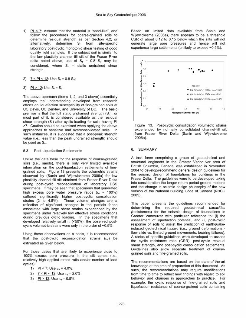
The above approach (Items 1, 2, and 3 above) essentially employs the understanding developed from research efforts on liquefaction susceptibility of fine-grained soils at UC Davis, UC Berkley, and University of BC. The basic premise is that the full static undrained strength (Su), or most part of it, is considered available as the residual shear strength (Sr) after cyclic loading for soils having PI >7. Caution should be exercised when applying the above approaches to sensitive and overconsolidated soils. In such instances, it is suggested that a post-peak strength value (i.e., less than the peak undrained strength) should be used as Su. 5.3 Post-Liquefaction Settlements Unlike the data base for the response of coarse-grained soils (i.e., sands), there is only very limited available information on the post-liquefaction settlements of fine-grained soils. Figure 13 presents the volumetric strains observed by (Sanin and Wijewickreme 2006a) for low plasticity channel-fill silt obtained from Fraser River Delta during post-cyclic reconsolidation of laboratory DSS specimens. It may be seen that specimens that generated high excess pore water pressure ratios (ru ~ 100%) suffered significantly higher post-cyclic consolidation strains (2 to 4.5%). These volume changes are a reflection of significant changes in the particle fabric associated with large shear strains experienced by the specimens under relatively low effective stress conditions during previous cyclic loading. In the specimens that developed relatively small ru (<50%), the observed post-cyclic volumetric strains were only in the order of ~0.5%. Using these observations as a basis, it is recommended that the post-cyclic reconsolidation strains (εv) be estimated as given below. For those cases that are likely to experience close to 100% excess pore pressure in the silt zones (i.e., relatively high applied stress ratio and/or number of load cycles):
1) PI < 7: Use εv = 4.0%; 2) 7 < PI < 12: Use εv = 2.0%; 3) PI > 12: Use εv = 0.5%.
Based on limited data available from Sanin and Wijewickreme (2006a), there appears to be a threshold CSR of about 0.12 to 0.15 below which the silts will not generate large pore pressures and hence will not experience large settlements (unlikely to exceed ~0.5%).
6. SUMMARY A task force comprising a group of geotechnical and structural engineers in the Greater Vancouver area of British Columbia, Canada, was established in November 2004 to develop/recommend general design guidelines for the seismic design of foundations for buildings in the Fraser Delta. The guidelines were to be developed taking into consideration the longer return period ground motions and the change in seismic design philosophy of the new version of the National Building Code of Canada (NBCC 2005). This paper presents the guidelines recommended for determining the required geotechnical capacities (resistances) for the seismic design of foundations in Greater Vancouver with particular reference to: (i) the assessment of liquefaction potential, and (ii) post-cyclic response of soils to assist the prediction of earthquake-induced geotechnical hazard (i.e., ground deformations - flow slide vs. limited ground movements, bearing failures). A series of specific guidelines were developed to assess the cyclic resistance ratio (CRR), post-cyclic residual shear strength, and post-cyclic consolidation settlements. Guidelines also allow separate treatment of coarse-grained soils and fine-grained soils. The recommendations are based on the state-of-the-art knowledge at the time of preparation of this document. As such, the recommendations may require modifications from time to time to reflect new findings with regard to soil behavior and changes in approaches to practice. For example, the cyclic response of fine-grained soils and liquefaction resistance of coarse-grained soils containing
0.0
0.2
0.4
0.6
0.8
1.0
1.2
0.0 1.0 2.0 3.0 4.0 5.0 6.0
Post-cyclic Volumetric S train (%)
Maxim
um E
xces
s Por
e Wat
er P
ress
ure R
atio
, Δ
u/σ
'
Test Series
vo
II(a) Nominal σ'vo = 100kPa. ec(ave) = 0.931
II(b) Nominal σ'vo = 85kPa. ec(ave) = 0.963
II(c) Nominal σ'vo = 200kPa. ec(ave) = 0.879
Figure 13. Post-cyclic consolidation volumetric strains experienced by normally consolidated channel-fill silt from Fraser River Delta (Sanin and Wijewickreme 2006a).
1276
Sea to Sky Geotechnique 2006
fines content are topics that are currently under discussion by the engineering community, and the authors believe that some changes may be appropriate over time with regard to design approaches in these areas. 7. ACKNOWLEDGEMENTS Invaluable review input provided by the members of the Task Force Report (especially Dr. John Howie, Mr. Ernie Naesgaard, Dr. Alex Sy, and Dr. Upul Atukorala) in the development of the guidelines is gratefully acknowledged. Seismic Resistance subcommittee of the Task Force comprised the following individuals: Dr. Peter Byrne, Dr. Dharma Wijewickreme, Dr. John Howie, Mr. Keith Robinson, Mr. Doug Wallis, and Dr. Li Yan). Some of components of the information presented herein are a direct result of the research funding provided by Natural Sciences and Engineering Council of Canada (NSERC). References
Anderson, D.L. (2006) Selection of earthquake magnitude
and ground motion records for liquefaction assessment. Proceedings of the 59th Canadian Geotechnical Conference, Vancouver, B.C., Canada (this conference).
Andrus, R.D. and Stokoe II, K.H. (2000) Liquefaction resistance of soils from shear-wave velocity. Journal of Geotechnical and Geoenvironmental Engineering, ASCE, 126(11):1015-1025.
Boulanger, R.W. and Idriss, I.M. (2004) Evaluation of potential for liquefaction or cyclic failure of silts and clays, Report No. UCD/CGM-04/01, Department of Civil & Environmental Engineering, University of California at Davis.
Boulanger, R.W., Meyers, M.W., Mejia, L.H. and Idriss, I.M. (1998) Behavior of a fine-grained soil during the Loma Prieta earthquake, Canadian Geotechnical Journal, 35(1): 146-158.
Bray, J.D., Sancio, R.B., Riemer, M.F. and Durgunoglu, T. (2004) Liquefaction susceptibility of fine-grained soils, Proceedings of the 11th International Conference on Soil Dynamics and Earthquake Engineering and 3rd International Conference on Earthquake Geotechnical Engineering, Jan. 7-9, Berkeley, CA: 655-662.
Castro, G. (1975) Liquefaction and cyclic mobility of saturated sands, Journal of the Geotechnical Engineering Division, ASCE, 101(GT6): 551-569.
Daniel, C.R., Howie, J.A. and Sy, A. (2003) A method for correlating Large Penetration Tests (LPT) to Standard Penetration Test (SPT) blow counts, Canadian Geotechnical Journal, 40(1): 66-77.
DeVall, R. (2006). The 1 in 2475 Earthquake and how it affects the way Structural Engineers think about Seismic Structural Design of Buildings and is this thinking applicable to aspects of geotechnical engineering - a Personal Perspective. Proceedings of the 59th Canadian Geotechnical Conference, Vancouver, B.C., Canada (this conference).
Finn, W.D.L., Ledbetter, R.H. and Wu, G. (1994) Liquefaction in silty soils: Design and analysis, Ground failures under seismic conditions, Geotechnical Special Publication, ASCE, 44: 51 – 76.
Finn, W.D.L. and Wightman, A. (2006) The application of NBCC2005 probabilistic ground motions to liquefaction assessments, Proceedings of the 59th Canadian Geotechnical Conference, Vancouver, B.C., Canada (this conference).
Harder, L.F., Jr. and Boulanger, R. (1997) Application of Kα and Kσ correction factors, Proceedings of the NCEER Workshop on Liquefaction Resistance of Soils, Edited by T.L. Youd and I.M. Idriss, Technical Report NCEER-97-0022, National Center for Earthquake Engineering Research, State University of New York at Buffalo, N.Y.: 167-190.
Harder, L.F., Jr. and Seed, H.B. (1986) Determination of penetration resistance for coarse-grained soils using the Becker Hammer Drill, Report UCB/EERC-86/06, Earthquake Engineering Research Center, University of California, Berkeley.
Ishihara, K., Tatsuoka, F. and Yasuda, S. (1975) Undrained deformation and liquefaction under cyclic stresses, Soils and Foundations, 15(1): 29-44.
Koester, J.P. (1992) The influence of test procedure on correlation of Atterberg limits with liquefaction in fine-grained soils, Geotechnical Testing Journal, 15(4): 352 – 361.
Kokusho, T. (2003) Current state of research on flow failure considering void redistribution in liquefied deposits, Journal of Soil Dynamic and Earthquake Engineering, 23: 585–603.
Kuerbis R.H., Negussey, D. and Vaid, Y.P. (1988) Effect of gradation and fines content on the undrained response of sand, Edited by: Van Zyl DJA, Vick SG, Geotechnical Special Publication No. 21. Hydraulic Fill Structures, Geotechnical Engineering Division, ASCE, Fort Collins, CO; 330-345.
Kulasingam, R., Malvick, E.J., Boulanger, R.W. and Kutter, B.R. (2004) Strength loss and localization at silt interlayers in slopes of liquefied sand, Journal of Geotechnical and Geoenvironmental Engineering, ASCE, 130(11): 1192-1202.
Kutter B.R., Gajan, S. G., Manda K.K. and Balakrishnan, A. (2004) Effects of layer thickness and density on settlement and lateral spreading, Journal of Geotechnical and Geoenvironmental Engineering, ASCE, 130(6): 603-614.
Naesgaard, E., Byrne, P.M., Seid-Karbasi, M. and Park, S.S. (2005) Modeling flow liquefaction, its mitigation, and comparison with centrifuge tests, Proceedings of the ICSMGE TC4 Satellite Conference on Recent Developments in Earthquake Engineering, Osaka, Japan, September 2005: 95-102.
NBCC (2005), National Building Code of Canada, National Research Council Canada.
NBCC (1995), National Building Code of Canada, National Research Council Canada.
Olson, S.M. and Stark, T.D. (2002) Liquefied strength ratio from liquefaction flow failure case histories, Canadian Geotechnical Journal, 39(3): 629–647.
1277
Sea to Sky Geotechnique 2006
Robertson, P.K. and Wride, C.E. (1998) Evaluating cyclic liquefaction potential using the cone penetration test, Canadian Geotechnical Journal, 35(3): 442-459.
Sanin, M.V. and Wijewickreme, D. (2006a) Cyclic shear response of channel-fill Fraser River Delta silt. Soil Dynamics and Earthquake Engineering, 26(9): 854-869.
Sanin, M. and Wijewickreme, D. (2006b) Influence of initial confining stress on the mechanical response of natural Fraser River Delta silt, Proceedings of the 59th Canadian Geotechnical Conference, Vancouver, B.C., Canada. (this conference).
Seed, R.B., Cetin, K.O., Moss, R.S., Kammerer, A.M., Wu, J., Pestana, J.M., Riemer, M.F., Sancio, R.B., Bray, J.D., Kayen, R.E. and Faris, A. (2003) Recent advances in soil liquefaction engineering: a unified and consistence framework, 26th annual ASCE Terzaghi lecture, keynote presentation.
Seed, R.B. and Harder, L.F., Jr. (1990) SPT-based analysis of cyclic pore pressure generation and undrained residual strength, Proceedings of the H.B. Seed Memorial Symposium, Bi-Tech Publishing Ltd., 2: 351–376.
Seid-Karbasi, M. and Byrne, P.M. (2004) Liquefaction, lateral spreading and flow slides, Proceedings of the 57th Canadian Geotechnical Engineering Conference, Quebec City, PQ, Canada, October 2004
Sy, A. and Campanella, R.G. (1994) Becker and standard penetration tests (BPT-SPT) correlations with consideration of casing friction, Canadian Geotechnical Journal, 31(3): 343-356.
Task Force Report (1991) Earthquake Design in the Fraser River Delta, Task Force Report, Soil Mechanics Series, No. 150, The University of British Columbia, Vancouver, Canada.
Task Force Report (In Press) Geotechnical Design Guidelines for Buildings on Liquefiable Sites in Greater Vancouver in Accordance with NBCC 2005, Greater Vancouver Seismic Geotechnical Design Task Force, Vancouver, BC, Canada.
Thevanayagam, S., Shenthan, T., Mohan, S. and Liang, J. (2002) Undrained Fragility of Clean Sands, Silty Sands, and Sandy Sands, Journal of Geotechnical and Geoenvironmental Engineering, ASCE, 128(10): 849-59.
Vaid, Y.P. and Finn, W.D.L. (1979) Static shear and liquefaction potential, Journal of the Geotechnical Engineering Division, ASCE, 105(GT10): 1233-1246.
Vaid, Y.P. and Thomas, J. (1995) Liquefaction and post-liquefaction behaviour of sand, Journal of Geotechnical Engineering, ASCE, 121(2): 163-173.
Wang, W.S. (1979) Some findings in soil liquefaction, Water Conservancy and Hydroelectric Power, Scientific Research Institute, Beijing, China.
Wijewickreme, D., Sriskandakumar, S., Byrne, P.M. (2005) Cyclic loading response of loose air-pluviated Fraser River sand for validation of numerical models simulating centrifuge tests, Canadian Geotechnical Journal, 42(2): 550-561.
Wu, J. (2002) Liquefaction Triggering and Post Liquefaction Deformations of Monterey 0/30 Sand Under Uni-Directional Cyclic Simple Shear Loading, PhD Dissertation, University of California, Berkeley, Calf.
Youd, T.L., Idriss, I.M., Andrus, R.D., Arango, I., Castro, G., Christian, J.T., Dobry, R., Finn, W.D.L., Harder, L.F., Jr., Hynes, M.E., Ishihara, K., Koester, J.P., Liao, S.S.C., Marcuson III, W.F., Martin, G.R., Mitchell, J.K., Moriwaki, Y., Power, M.S., Robertson, P.K., Seed, R.B. and Stokoe II, K.H. (2001) Liquefaction Resistance of Soils: Summary Report from the 1996 NCEER and 1998 NCEER/NSF Workshops on Evaluation of Liquefaction Resistance of Soils, Journal of Geotechnical and Geoenvironmental Engineering, ASCE, 127(10): 817-833.
Youd, T. L. and Noble, S. K. (1997) Magnitude scaling factors, Proceedings of NCEER Workshops on Evaluation of Liquefaction Resistance of soils, National Centre For Earthquake Engineering, Res., State Univ. of New York at Buffalo: 149 -165.
Zhang, G., Robertson, P.K. and Brachman, R.W.I (2002) Estimating liquefaction-induced ground settlements from CPT for level ground, Canadian Geotechnical Journal, 39: 1168-1180.
1278
Sea to Sky Geotechnique 2006