liquid cooling guidelines for datacom equipment centers
TRANSCRIPT

Data center IT equipment today is predominantly air cooled. However, with rack heat loadssteadily climbing, the ability for many data centers to deliver either adequate airflow rates orsufficient chilled air is now being stretched to the limit. These trends in the heat load generatedfrom IT equipment can have detrimental side effects, such as decreased equipment availability,wasted floor space, and inefficient cooling system operation. This situation is creating a needfor implementing liquid cooling solutions. The overall goals of the liquid implementationsinclude aspects such as transferring as much waste heat to the facility liquid cooling loop aspossible, reducing the overall volume of airflow needed by the racks, and reducing processortemperatures such that increased compute performance can be achieved.
This book on liquid cooling is divided into six chapters and includes definitions for liquidand air cooling as it applies to the IT equipment, describing the various liquid loops that canexist in a building that houses a data center. It also provides the reader an overview of thechilled water and condenser water systems and an overview of datacom equipment coolingoptions. The book also bridges the liquid cooling systems by providing guidelines on theinterface requirements between the chilled water system and the technology cooling systemand outlines the requirements of those liquid-cooled systems that attach to a datacom electronicsrack and are implemented to aid in data center thermal management.
This book is the fourth in a series of datacom books published by ASHRAE and authored byTC 9.9, Mission Critical Facilities, Technology Spaces, and Electronic Equipment. The otherbooks, listed in order of publication, are Thermal Guidelines for Data Processing Environments,Datacom Equipment Power Trends and Cooling Applications, and Design Considerations forDatacom Equipment Centers.
ISBN: 1-933742-05-4
90430American Society of Heating, Refrigerating and Air-Conditioning Engineers, Inc.
Liquid CoolingGuidelinesfor DatacomEquipment Centers
Liquid CoolingGuidelinesfor DatacomEquipment Centers
ASHRAE Datacom SeriesASHRAE Datacom Series
Liquid C
ooling Guidelines for D
atacom E
quipment C
entersA
SH
RA
E D
atacom S
eries

Liquid Cooling Guidelines for Datacom Equipment Centers

This publication was prepared in cooperation with TC 9.9, Mission Critical Facilities,Technology Spaces, and Electronic Equipment.
Any updates/errata to this publication will be posted on the
ASHRAE Web site at www.ashrae.org/publicationupdates.

American Society of Heating, Refrigeratingand Air-Conditioning Engineers, Inc.
Liquid Cooling Guidelines for Datacom Equipment Centers

ISBN-10: 1-933742-05-4ISBN-13: 978-1-933742-05-2
©2006 American Society of Heating, Refrigeratingand Air-Conditioning Engineers, Inc.
1791 Tullie Circle, NEAtlanta, GA 30329
www.ashrae.org
All rights reserved.Printed in the United States of America
Printed on 30% post-consumer waste using soy-based inks.
ASHRAE has compiled this publication with care, but ASHRAE has not investigated, and ASHRAEexpressly disclaims any duty to investigate, any product, service, process, procedure, design, or the likethat may be described herein. The appearance of any technical data or editorial material in this publi-cation does not constitute endorsement, warranty, or guaranty by ASHRAE of any product, service,process, procedure, design, or the like. ASHRAE does not warrant that the information in the publi-cation is free of errors, and ASHRAE does not necessarily agree with any statement or opinion in thispublication. The entire risk of the use of any information in this publication is assumed by the user.
No part of this book may be reproduced without permission in writing from ASHRAE, except by areviewer who may quote brief passages or reproduce illustrations in a review with appropriate credit;nor may any part of this book be reproduced, stored in a retrieval system, or transmitted in any wayor by any means—electronic, photocopying, recording, or other—without permission in writing fromASHRAE.
____________________________________________
Library of Congress Cataloging-in-Publication Data
Liquid cooling guidelines for datacom equipment centers. p. cm. Includes bibliographical references and index. ISBN 978-1-933742-05-2 (pbk.) 1. Data processing service centers--Cooling. 2. Hydronics. 3. Electronic apparatus and appliances--Cooling. 4. Electronic digital computers--Cooling. I. American Society of Heating, Refrigerating and Air-Conditioning Engineers.
TH7688.C64L57 2006 697.9'316--dc22 2006026115
ASHRAE STAFF
SPECIAL PUBLICATIONS
Mildred GeshwilerEditor
Christina HelmsAssociate Editor
Cindy Sheffield MichaelsAssistant Editor
Michshell PhillipsAdministrative Assistant
PUBLISHING SERVICES
David SoltisManager
Tracy BeckerGraphic Applications Specialist
Jayne JacksonPublication Traffic Administrator
PUBLISHER
W. Stephen Comstock

Contents
Acknowledgments. . . . . . . . . . . . . . . . . . . . . . . . . . . . . . . . . . . . . . . . . .vii
Chapter 1 Introduction. . . . . . . . . . . . . . . . . . . . . . . . . . . . . . . . . . . . . . 1
1.1 Definitions . . . . . . . . . . . . . . . . . . . . . . . . . . . . . . . . . . . . . . . . . 2
1.2 Liquid Cooling Systems . . . . . . . . . . . . . . . . . . . . . . . . . . . . . . 4
Chapter 2 Facility Cooling Systems . . . . . . . . . . . . . . . . . . . . . . . . . . . 7
2.1 Introduction . . . . . . . . . . . . . . . . . . . . . . . . . . . . . . . . . . . . . . . . 7
2.2 Equipment. . . . . . . . . . . . . . . . . . . . . . . . . . . . . . . . . . . . . . . . 12
2.3 Heat Rejection Equipment . . . . . . . . . . . . . . . . . . . . . . . . . . . 15
2.4 Pumps. . . . . . . . . . . . . . . . . . . . . . . . . . . . . . . . . . . . . . . . . . . 16
2.5 Energy Recovery Equipment . . . . . . . . . . . . . . . . . . . . . . . . . 17
Chapter 3 Facility Piping Design . . . . . . . . . . . . . . . . . . . . . . . . . . . . 21
3.1 General . . . . . . . . . . . . . . . . . . . . . . . . . . . . . . . . . . . . . . . . . . 21
3.2 Spatial Considerations . . . . . . . . . . . . . . . . . . . . . . . . . . . . . . 22
3.3 Basic Piping Architecture . . . . . . . . . . . . . . . . . . . . . . . . . . . . 22
3.4 Piping Arrangements for the Cooling Plant. . . . . . . . . . . . . . . 32
3.5 Water Treatment Issues . . . . . . . . . . . . . . . . . . . . . . . . . . . . . 35
3.6 Earthquake Protection . . . . . . . . . . . . . . . . . . . . . . . . . . . . . . 35
Chapter 4 Liquid Cooling Implementation forDatacom Equipment. . . . . . . . . . . . . . . . . . . . . . . . . . . . . 37
4.1 Overview of Liquid-Cooled Racks and Cabinets. . . . . . . . . . . 37
4.2 Overview of Air- and Liquid-Cooled Datacom Equipment . . . 42
4.3 Overview of Coolant Distribution Unit (CDU) . . . . . . . . . . . . . 45

vi ⏐ Contents
Chapter 5 Liquid Cooling Infrastructure Requirementsfor Chilled-Water Systems . . . . . . . . . . . . . . . . . . . . . . . .53
5.1 Building Facility Chilled-Water Systems (CHWS) . . . . . . . . . .53
5.2 Non-Chilled-Water Facility Systems. . . . . . . . . . . . . . . . . . . . .69
Chapter 6 Liquid Cooling Infrastructure Requirementsfor Technology Cooling Systems. . . . . . . . . . . . . . . . . . .73
6.1 Water-Based Technology Cooling System. . . . . . . . . . . . . . . .73
6.2 Non-Water-Based Technology Cooling System . . . . . . . . . . . .77
References and Bibliography . . . . . . . . . . . . . . . . . . . . . . . . . . . . . . . .79
Glossary of Terms . . . . . . . . . . . . . . . . . . . . . . . . . . . . . . . . . . . . . . . . .81
Appendix . . . . . . . . . . . . . . . . . . . . . . . . . . . . . . . . . . . . . . . . . . . . . . . . .87
Index . . . . . . . . . . . . . . . . . . . . . . . . . . . . . . . . . . . . . . . . . . . . . . . . . . . .89

Acknowledgments
Representatives from the following companies participated in producingthis publication:
APC
Aavid
Cray Inc.
Dell Computers
DLB Associates Consulting Engineers
EYPMCF
Hewlett Packard
IBM
Intel Corporation
Lawrence Berkeley National Labs
Liebert Corporation
Lytron
Mallory & Evans, Inc.
NCR
Department of Defense
Panduit
Rittal
Sanmina
SGI
Spraycool
Syska & Hennessy Group, Inc.
Sun Microsystems
Trane
ASHRAE TC 9.9 wishes to particularly thank the following people:
• Don Beaty, John Bean, Christian Belady, Tahir Cader, David Copeland,Rhonda Johnson, Tim McCann, David Moss, Shlomo Novotny, GregPautsch, Terry Rodgers, Jeff Rutt, Tony Sharp, David Wang, andKathryn Whitenack for their participation and continual improvements inthe final document.
• Don Beaty of DLB Associates Consulting Engineers, Jeff Rutt of Depart-ment of Defense, and Kathryn Whitenack of Lytron for providing the coor-dination and leadership on developing the individual chapters.
vii

viii ⏐ Acknowledgments
• Dr. Roger Schmidt for his invaluable participation in leading the overalldevelopment of the book.
In addition, ASHRAE TC 9.9 wishes to thank the following people for theircomments and feedback: William Angle, Cullen Bash, Neil Chauhan, BrianDonabedian, Jack Glass, Chris Malone, Vance Murakami, Larry Rushing, PrajbitSingh, William Tschudi, and Randy Zoodsma.

1
Introduction
From a holistic point of view, the data center, with its installed information tech-nology (IT) equipment, introduces several levels of cooling. First there is the utilityplant that provides the overall cooling to the data center. This utility plant may be astand-alone building dedicated solely to the data center or, as is more typically the case,part of a larger building that provides cooling to other locations within the buildingwhere the data center is housed. The utility plant that provides the cooling to the build-ing/data center generally employs large chillers that are used to chill the building’swater loop. The chilled water can be used to provide cooling to modular computerroom air-conditioning (CRAC) units situated inside a data center or to large air-handling units installed externally to the data center (even to the building). Air condi-tioning for the data center can also be provided by refrigeration units, e.g., DX unitsor expansion type devices, whereby the condenser unit is generally placed outside thebuilding envelope. In this case, no water is delivered to the data center floor.
Data center IT equipment today is generally air-cooled by the meansdescribed in the preceding paragraph. With rack heat loads steadily climbing, theability for many data centers to deliver either adequate airflow rates or sufficientchilled air is now being stretched to the limit. This situation is creating a need forimplementing liquid cooling solutions. The overall goals of the liquid implemen-tations are to transfer as much waste heat to the facility water as possible and, insome of the implementations, to reduce the overall volume of airflow needed bythe racks. In addition, implementation of liquid cooling may be required to achievehigher performance of the datacom equipment through lower temperaturesachieved with the cooling of microprocessors.
This book, which was generated by ASHRAE Technical Committee 9.9,provides equipment manufacturers and facility operations personnel with a commonset of guidelines for liquid cooling. This publication is not inclusive of all types ofliquid cooling sources (e.g., absorption chillers) but is representative of generallyaccepted liquid cooling systems. It covers an overview of liquid cooling, variousliquid cooling configurations, and guidelines for liquid cooling infrastructurerequirements. Specifically, this book provides guidelines for:
1

2⏐ Introduction
• Chilled-water operational requirements (Section 5.1.1.1)• Chilled-water flow rate recommendations and fouling factors (Section 5.1.1.2)• Chilled-water velocity considerations (Section 5.1.1.3)• Chilled-water liquid quality/composition (Section 5.1.1.4)• Chilled-water wetted material requirements (Section 5.1.1.5)• Refrigerant piping (Section 5.2.2)• Rack-water operational requirements (Section 6.1.1)• Rack-water flow rates (Section 6.1.2)• Rack-water velocity considerations (Section 6.1.3)• Rack-water quality/composition (Section 6.1.4)• Rack-water wetted materials requirements (Section 6.1.5)• Rack-nonwater operational requirements (Section 6.2.1)
It also reviews considerations for:
• Chilled-water piping• Electrical power sources and connections• Monitoring• Reliability and availability• Commissioning
The following chapters are arranged to describe the various liquid coolingsystems that can exist within a data center and, more importantly, how they can beconnected to transfer heat from one liquid system to another. Chapters 2 and 3provide the reader with an overview of the chilled-water and condenser-watersystems (see Figure 1.1), followed by an overview of datacom equipment coolingoptions (technology cooling system and datacom equipment cooling system shownin Figure 1.1) in Chapter 4. Chapter 5 bridges the liquid cooling systems by provid-ing guidelines on the interface requirements between the chilled-water system andthe technology cooling system. Chapter 6 outlines the requirements of those liquid-cooled systems that attach to a datacom electronics rack and are implemented to aidin data center thermal management by focusing on the technology cooling system.Chapter 7 provides an expanded reference and bibliography list to enable the readerto find additional related materials. Chapter 8 provides a useful glossary of commonterms used throughout this book. An appendix is also included that provides surveyresults of customer water quality.
1.1 DEFINITIONS
For the purposes of this book, the following definitions will be used:
• Liquid cooling is defined as the case where liquid must be supplied to anentity for operation.

Liquid Cooling Guidelines for Datacom Equipment Centers⏐3
• Liquid-cooled rack defines the case where liquid must be circulated to andfrom the rack or cabinet for operation.
• Liquid-cooled datacom equipment defines the case where liquid must be cir-culated to and from the datacom equipment for operation.
• Liquid-cooled electronics defines the cases where liquid is supplied directly tothe electronics for cooling with no other form of heat transfer.
In each of the definitions above, when two-phase liquid cooling is employed,liquid is circulated to the rack, equipment, or electronics, and gas and/or a mixtureof gas and liquid circulates from the rack, equipment, or electronics. These liquidcooling definitions are slightly broader than the one used in ASHRAE’s DatacomEquipment Power Trends and Cooling Applications but are more relevant to liquidcooling in the datacom industry today.
It is important to keep in mind that the definitions above do not limit the coolingfluid to water. A variety of liquids could be considered for application, includingliquids that could be in a vapor phase in part of the cooling loop.
• Air cooling defines the case where only air must be supplied to an entityfor operation.
• Air-cooled rack defines the case where only air must be provided to the rackor cabinet for operation.
• Air-cooled datacom equipment defines the case where only air is provided tothe datacom equipment for operation.
• Air-cooled electronics defines the cases where air is provided directly to theelectronics for cooling with no other form of heat transfer.
When liquids are employed within separate cooling loops that do not commu-nicate thermally, the system is considered to be air cooling. The most obvious illus-tration covers the chilled-water CRACs that are usually deployed at the periphery ofmany of today’s data centers. At the other end of the scale, the use of heat pipes orpumped loops inside a computer, wherein the liquid remains inside a closed loopwithin the server, also qualifies as air-cooled electronics, provided the heat is removedfrom the internal closed loop via airflow through the electronic equipment chassis.
There are many different implementations of liquid cooling to choose from.Below are several scenarios (see Chapter 4 for a more complete overview of liquidcooling implementations).
• One option uses an air-cooled refrigeration system mounted within the data-com equipment to deliver chilled refrigerant to liquid-cooled cold platesmounted to the processors. For this implementation, the heated air from theliquid-to-air heat exchanger (i.e., condenser) is exhausted directly to the datacenter environment. From a data center perspective, the rack and electronicsare considered to be air-cooled since no liquid lines cross the rack envelope.

4⏐ Introduction
• A different implementation may use a liquid-to-air heat exchanger mountedabove, below, or on the side or rear of the rack. In this case, the heatexchanger removes a substantial portion of the rack’s waste heat from the airthat is eventually exhausted to the data center. This implementation does notreduce the volumetric airflow rate needed by the electronics, but it doesreduce the temperature of the air that is exhausted back into the data center.This example describes a liquid-cooled rack since liquid lines cross the rackenvelope. This system is shown in Figure 4.8.
• Yet another implementation uses liquid-cooled cold plates that employ water,dielectrics, or other types of coolants that are chilled by a liquid-to-liquid heatexchanger that rejects the waste heat to the facility water. The waste heatrejection to the facility water can occur via one or more additional liquidloops that eventually terminate at an external cooling tower or chiller plant.This implementation of liquid cooling reduces the amount of waste heatrejected to the facility ambient and also reduces the volumetric airflow raterequired by the rack’s electronics. From the data center perspective, thisimplementation describes liquid-cooled racks and electronics since liquidlines cross the rack envelope and also cross over into the servers themselves.This system is shown in Figure 4.10.
1.2 LIQUID COOLING SYSTEMS
The definitions above apply to air and liquid cooling in a data center. They donot define the various liquid cooling loops that may exist within a data center.Figure 1.1 shows a typical liquid-cooled facility with multiple liquid cooling loops.Each loop is described below with some of the variations considered. The termi-nology used below will be applied throughout the rest of the book.
datacom equipment cooling system (DECS): This system does not extend beyondthe IT rack. It is a loop within the rack that is intended to perform heat transfer fromthe heat-producing components (CPU, memory, power supplies, etc.) to a fluid-cooled heat exchanger also contained within the IT rack. Some configurations mayeliminate this loop and have the fluid from the coolant distribution unit (CDU) flowdirectly to the load. This loop may function in single-phase or two-phase heat trans-fer modes facilitated by heat pipes, thermosyphon, pumped fluids, and/or vapor-compression cycles. Fluids typically used in the datacom equipment include water,ethylene glycol or propylene glycol and water mixture, refrigerants, or dielectrics.At a minimum the datacom equipment cooling system would include a heat collec-tion heat exchanger as well as a heat-of-rejection heat exchanger and may be furtherenhanced with active components such as compressor/pump, control valves, elec-tronic controls, etc.

Liquid Cooling Guidelines for Datacom Equipment Centers⏐5
technology cooling system (TCS): This system would not typically extend beyondthe boundaries of the IT space. The exception is a configuration in which the CDUis located outside the data center. It serves as a dedicated loop intended to performheat transfer from the datacom equipment cooling system into the chilled-watersystem. This loop is highly recommended, as it is needed to address specific fluidquality issues regarding temperature, purity, and pressure as required by the heatexchangers within the datacom equipment cooling systems. Fluids typically used inthe technology cooling loop include water, ethylene glycol or propylene glycol andwater mixture, refrigerants, or dielectrics. This loop may also function by single-phase or two-phase heat transfer modes and may facilitate transfer by heat pipes, ther-mosyphon, pumped fluids, and/or vapor-compression cycles. At a minimum thetechnology cooling system would include a heat collection heat exchanger (likelyintegral component of the datacom equipment cooling system), a heat rejection heatexchanger, as well as interconnecting piping. This system may be further enhancedwith such active components as compressors/pumps, control valves, electroniccontrols, filters, hydronic accessories, etc.
chilled-water system (CHWS): This system is typically at the facility level and mayinclude a dedicated system for the IT space(s). It primarily consists of the systembetween the data center chiller(s) and the CDU. The chilled-water system wouldinclude the chiller plant, pumps, hydronic accessories, and necessary distributionpiping at the facility level. The chiller plant would typically employ a vapor-compression cycle to cool the chilled-water supply temperature (43°F–48°F/6°C–
Figure 1.1 Liquid cooling systems/loops within a data center.

6⏐ Introduction
9°C) substantially below indoor ambient temperature (typically 75°F/24°C and upto and beyond 95°F/35°C). The chiller system may offer some level of redundancyfor critical components such as chillers, cooling towers, and pumps.
DX equipment can also be used in the chilled-water system. DX equipmentprovides direct heat dissipation to the atmosphere and is therefore the last loop forthat design method. Limitations include distance for the split systems and cost ofoperation. Generally, in most areas systems become economically breakeven at 400tons of refrigeration. Larger systems favor non-DX designs unless other circum-stances warrant more extensive DX deployment. Smaller thermal ride-throughdevices can be introduced for individual or special cases within this loop design.
condenser-water system (CWS): This system consists of the liquid loop betweenthe cooling towers and the data center chiller(s). It is also typically at the facilitylevel and may or may not include a dedicated system for the IT space(s). Condenser-water loops typically fall into one of two fundamental categories: wet-bulb-based ordry-bulb-based system. The wet-bulb-based loops function on an evaporativeprocess, taking advantage of lower wet-bulb temperatures, thereby providing coolercondenser-water temperatures. The dry-bulb-based loops function based upon thedifference of condenser-water loop temperature versus ambient dry-bulb tempera-ture. To allow heat transfer with the dry-bulb-based system, the condenser-waterloop must be at some temperature substantially above the ambient dry-bulb temper-ature to allow adequate heat transfer from the condenser-water into the outdoorambient air. These loops would typically include: outdoor heat rejection device(cooling tower or dry fluid cooler), pumps, expansion tanks, hydronic accessories,and distribution piping.
Any of these systems can be eliminated. For instance, in an installation wherethe CDU fluid flows directly to the load, the datacom equipment cooling system iseliminated or, where fluid from the chilled-water system flows to a heat exchangerin the rack (this is strongly discouraged), the technology cooling system is elimi-nated or the technology cooling system and datacom equipment cooling system areeliminated (again, this is strongly discouraged).
General ranges for air-cooled equipment and evaporative water cooling as wellas the refrigerant types and compressor efficiencies result in a unique engineeringdesign for each data center. For cooling component selection, the design engineermust consider economical operation, first cost, expandability, reliability, redundancy,and fault tolerance. To complicate the design further, all of the systems are interre-lated. For example, undersize one loop and that will limit the successive removal ofheat to the next level. When designing a data center, the interdependence must beevaluated. ASHRAE’s Datacom Book Series (specifically, Design Considerationsfor Datacom Equipment Centers, Datacom Equipment Power Trends and CoolingApplications, and Thermal Guidelines for Data Processing Environments) providesmore details about the various systems and their design requirements.

2
Facility Cooling Systems
2.1 INTRODUCTION
Facility cooling systems can vary in configuration and equipment. Time andcost pressures can cause a disproportionate focus on simply designing coolingsystems that deliver the capacity needed and ignoring other critical considerations.However, the focus should be much broader and balance the various considerationsand trade-offs, such as flexibility; scalability; ease of installation, commissioning,and operation; ease of maintenance and troubleshooting; and availability and reli-ability. Any one or combination of the five considerations just mentioned can signif-icantly change how the facility cooling systems are designed, what equipment isused, and the overall system architecture.
2.1.1 Flexibility
Data center cooling systems should be designed with features that will mini-mize or eliminate system outages associated with new equipment installation.These features should be added to both the central plant cooling systems and build-ing chilled-water piping architecture. Some of these features include valved andcapped piping connections for future equipment, such as water-cooled racks,central station air handlers, CRACs, and central plant equipment. The central plantshould be configured to add additional chillers, pumps, and cooling towers as theload increases. A properly managed load and growth plan or strategy should bedeveloped and employed to incorporate future computer and cooling systems.
Overall flexibility is often limited by the pipe sizes used in the central plantand distribution system. After a data center is online, changing pipe size toincrease capacity is typically prohibitive from both outage risk and implementa-tion cost perspectives.
7

8⏐ Facility Cooling Systems
2.1.2 Scalability
The building cooling systems should be designed to accommodate future loadgrowth of the computer equipment. Unless adequately planned growth and expan-sion is included in the data center, it will be obsolete in a very short time. Computertechnology changes every two to five years, and the cooling system will need to beexpanded to accommodate this load growth. Therefore, building piping architecture(CWS and CHWS) should be designed to support a future building cooling loaddensity. Although first cost often dictates pump selection and pipe sizing, pumpingenergy, flexibility, and chilled-water storage will need to be considered to determinea total cost of ownership.
The central plant should have enough space for future chillers, pumps, and cool-ing towers. The central plant chilled- and condenser-water system pipe headersshould be sized to operate efficiently from day one through the ramp up and for thefuture projected load.
Sizing piping for the full buildout or future growth will save energy and allowsmaller active components during the early life of the building. If the budget doesnot allow for any additional building costs for future growth, the owner needs tomake sure that real estate is available next to the existing central plant.
2.1.3 Ease of Installation, Commissioning, and Operation
Cooling service equipment should be designed such that it can be installed ineasy, visible, and readily accessible locations.
Commissioning is an effective strategy to verify that the cooling systems areoperating as intended in the original building design and should be considered forevery project. In Design Considerations for Datacom Equipment Centers (ASHRAE2005a), Chapter 12 provides helpful information regarding cooling services forequipment cooling systems. This chapter details the five steps of formal commission-ing activities, starting with the facility’s intent and performance requirements (asdetermined by the project team), and following with the Owner’s Program document,the Basis-of-Design document, and the project Commissioning Plan. These activitiesinclude factory acceptance tests, field component verification, system constructionverification, site acceptance testing, and integrated systems testing.
Commissioning at full load (full flow) to prove hydraulic capacity should be arequirement. Loop isolation segments should be commissioned to prove circulationcapacity around each segment with looped supply and return to provide concurrentmaintainability without loss of cooling service.
Data centers should be designed with a central control or command center tooversee building operations. The control center should house all of the building oper-ations systems, such as security monitoring, energy management and controlsystems (EMCS), system control and data acquisition (SCADA) systems, buildingautomation systems (BAS), and fire alarms. This control can be co-located with thecomputer system control room. It should be staffed for 24-hour operation. All emer-

Liquid Cooling Guidelines for Datacom Equipment Centers⏐9
gency procedures, protocols, and a personnel list should be included in the controlcenter and updated as changes occur. Power and cooling loads on facility equipment,such as UPS, chillers, and electrical feeders, should be monitored to determine loadgrowth and available capacity. Configuration management groups or boards,consisting of IT and facilities departments, should be established to control andmanage data center infrastructure.
2.1.4 Ease of Maintenance and Troubleshooting
The ease of maintenance and the ability to troubleshoot problems quickly andaccurately are essential elements of a high-availability datacom facility. The firstelement of this planning should be to maintain adequate working clearance aroundcooling equipment. Manufacturers’ recommendations for working clearancesshould be used as a minimum for serviceability areas. Designers need to provideaccess to allow maintenance and operation of valves, control devices and sensors,and large equipment. Lifts, hoists, and cranes may be mounted within the centralplant to help facilitate removal of heavy equipment and components. These devicesshould be incorporated into the existing structural members of the plant room. Forexample, a hoist and rail system could be placed above the chillers in the plant roomto facilitate rapid removal of end plates and/or compressors. Also, space should beprovided to facilitate demolition and removal of entire cooling system components,such as chillers. If space is at a premium, tube pull areas for each chiller can be sharedsince usually one chiller is being worked on at a time. Chilled and condenser waterpipes should be routed to avoid conflict with removal of cooling system equipment.Mechanical equipment, such as pumps and chillers, should be arranged in such amanner as to facilitate complete replacement. Isolation valves must also be locatedto allow for replacement without interrupting service, which makes layout andassembly of the entire piping system important.
Building owners should consider a computerized maintenance managementsystem (CMMS) to help manage equipment maintenance. These systems can recordmaintenance history and automatically dispatch work orders for future maintenance.Manufacturers’ specific maintenance requirements and frequencies can be input ordownloaded into the CMMS. It is much easier and desirable to coordinate equipmentoutages and maintenance than to deal with an unscheduled equipment failure due tolack of adequate maintenance.
Energy management and control systems (EMCS) or building automationsystems (BAS) sensors and device outputs can be trended over time and used forsystem diagnostics and troubleshooting. EMCS data can also be used to monitor andcharacterize system performance over time. For example, chiller amp readings and/or chilled-water temperature differentials and flows can be used to calculate andmonitor chiller efficiency and load growth. Control systems should have a fail-safecondition that allows mechanical flow and ON operation. Typical general buildingmanagement systems shut down on the loss of control. Data center systems shouldturn on to keep systems online.

10⏐ Facility Cooling Systems
Load growth over time can be compared to chilled-water capacity, and thisinformation can be used to project time frames for plant expansion or increase inindividual component capacity, i.e., replace an 800 ton chiller with a 1200 ton chiller.In addition, flowmeters and pressure sensors can be installed in the building coolingdistribution or secondary loop and used to monitor chilled-water flows and capac-ities in the piping architecture. This information can be used to determine the bestlocation in which to install the newest water-cooled computer equipment or used tocalibrate a network model of the chilled-water systems. Finally, analog thermome-ters, pressure gauges, and flow-measuring instrumentation (orifice plates, balancingvalves, etc.) should be installed in chilled-water piping and used to gain additionalinformation on system performance. Sensors need placement in both the primaryloop and the auxiliary loop to allow control if either part of the loop is being serviced.Manual operation may also be used if the alternate loop is temporary.
2.1.5 Availability and Reliability
A key to having a reliable system and maximizing availability is an adequateamount of redundant equipment to perform routine maintenance. If N represents thenumber of pieces to satisfy the normal cooling capacity, then often reliability stan-dards are considered in terms of redundant pieces compared to the baseline of N.Some examples would be:
• N + 1—full capacity plus one additional piece• N + 2—full capacity plus two additional pieces• 2N—twice the quantity of pieces required for full capacity• 2(N + 1)—full capacity plus one additional piece and the entire assembly repeated
again (backup site)
A critical decision is whether N should represent just normal conditions orwhether N includes full capacity during offline routine maintenance. For example,in an N + 1 redundancy scenario during routine maintenance of a single unit, theremaining capacity from N units is exactly what is required to meet the cooling load.If one of the N online units fails while another is under maintenance, the coolingcapacity of the online units is insufficient.
The determination of the facility load represented by N should also be madebased on local design conditions. ASHRAE has statistical design data based on0.4%, 1%, and 2% excursions on an annual basis. The 0.4%, 1%, and 2% designconditions are exceeded 35, 87, and 175 hours, respectively, in a typical year. As anexample, in Atlanta, the dry-bulb temperatures corresponding to the 0.4%, 1%, and2% conditions are 93.9°F, 91.5°F, and 89.3°F, respectively (ASHRAE 2004a).
In an N + 2 redundancy scenario, even if one unit is down for maintenance, thereis still an additional unit online above the required capacity that can compensate ifone of the online units fails. This scenario means that there is always a redundant unit

Liquid Cooling Guidelines for Datacom Equipment Centers⏐11
at all times, whereas N + 1 would have a redundant unit for the majority of the timebut not during routine maintenance.
The 2N and 2(N + 1) systems can apply to pipe work as well as components. A2N design will not need loop isolation valves since there is a complete backup system.However, due to the thermal inertia of the fluid in the systems, both systems must beoperational for seamless transfer without disruption if one system detects a fault.
These configurations of N + 1 through 2(N + 1) exemplify the significant vari-ation in the design of redundant systems to achieve equipment availability at leastequal to N. Overlaid on top of these configurations is the influence of human error.Many failures are caused by human error; some configurations improve reliabilityfrom a mechanical standpoint but may increase the potential for human error.
Chilled-water or thermal storage may be applied to the data center central cool-ing plant to minimize or eliminate computer equipment shutdown in the event of apower failure to the datacom facility. Chilled-water storage tanks are placed in thebuilding distribution chilled-water piping. In the event of a power failure, the chilled-water pumps use the UPS to provide a constant flow of chilled water to the equip-ment. The chilled-water tanks are used in conjunction with pumps to provide coolingwater. The tanks should be sized to have enough storage capacity to match the batteryrun time of the UPS systems. Once the generators are operational, the chillers andpumps will resume normal operation.
For more information refer to Design Considerations for Datacom Equip-ment Centers (ASHRAE 2005a). The following chapters in that documentprovide helpful information regarding cooling services for equipment coolingsystems:
• Chapter 4, “Computer Room Cooling Overview”—The relationship betweenmethods of heat rejection as accomplished by direct expansion versus chilled-water systems is described, along with the functional characteristics and inter-relationships of the refrigeration cycle, condensers, chillers, pumps, piping,and humidifiers. The chapter concludes with a description of control parame-ters and monitoring methodologies.
• Chapter 13, “Availability and Redundancy”—This chapter details aspects ofavailability, such as the concept of “five nines,” failure prediction, mean timebetween failure (MTBF), and mean time to repair (MTTR). Concepts ofredundancy, such as N + 1, N + 2, and 2N are introduced, defined, and dis-cussed. Diversity and human error, as well as some practical examples ofmethods to increase availability and redundancy, are presented.
• Chapter 14, “Energy Efficiency”—Specific topics include chilled-waterplants, CRAC units, fans, pumps, variable-frequency drives, humidity control,air- and water-side economizers, part-load operation, in-room airflow distri-bution, and datacom equipment energy efficiency.

12⏐ Facility Cooling Systems
2.2 EQUIPMENT
The facility cooling equipment is a broad topic and more detail can be obtainedin the ASHRAE Handbooks. For the scope of this book, only the chillers, heat rejec-tion equipment, energy recovery equipment, and pumps are covered.
2.2.1 Chillers
Chiller is the term used to describe mechanical refrigeration equipment thatproduces chilled water as a cooling output or end product (Figure 2.1). Basic infor-mation on chillers can be obtained from Chapter 38 of the 2004 ASHRAE Hand-book—HVAC Systems and Equipment (ASHRAE 2004a).
The chilled water produced by a chiller for building cooling is commonly42°F to 45°F (5.5°C to 7°C) but can be selected and designed to produce temper-atures that are higher or lower than this range. Often this temperature is too lowfor data center cooling. A warmer temperature will provide enough cooling with-out dehumidifying further and has the potential for significant energy savings. Thedownside to the higher temperature is that it takes more flow and, hence, largerpipes and/or pumps.
The chilled water can be 100% water or a mixture of water and glycol (to preventthe water from freezing if piping is run in an unconditioned or exterior area) plusother additives such as corrosion inhibitors. The capacity of chillers (and all otherheat transfer coils, such as heat exchangers and cooling coils) is influenced or de-rated when glycol or additives are included.
In a typical chilled-water configuration, the chilled water is piped in a loopbetween the chiller and the equipment cooling system. It is important to considerthe chiller’s part-load efficiency, since data centers often operate at less thanpeak capacity.
One way to classify chillers is the basic method of chiller heat rejection (air-cooled or water-cooled). For air-cooled chillers, the compressors reject the heat theygain to the atmosphere using air-cooled condenser sections (Figures 2.2 and 2.3).The majority of air-cooled chillers are located outside to facilitate heat rejection tothe atmosphere. However, due to spatial or other constraints, the air-cooled chillercomponents can be split from the heat rejection component (typically an air-cooledcondenser) located remotely from the chiller.
Figure 2.1 Generic chiller diagram.

Liquid Cooling Guidelines for Datacom Equipment Centers⏐13
Figure 2.2 Schematic overview of a generic air-cooled chiller flow.
Figure 2.3 Typical packaged air-cooled chiller.

14⏐ Facility Cooling Systems
Water-cooled chillers use a second liquid loop called the condenser water loop.The condenser water loop is typically connected to an open or closed cooling tower(evaporative heat rejection unit) as shown in Figure 2.4.
A water-cooled chiller is shown in Figure 2.5. Based on electrical consumptionper quantity of cooling produced and depending on the type of configuration used,water-cooled chillers are more energy efficient than the air-cooled equivalent. Moreinformation on chillers can be found in Chapter 38 of the 2004 ASHRAE Hand-book—HVAC Systems and Equipment (ASHRAE 2004a).
Figure 2.4 Schematic overview of a generic water-cooled chiller flow.
Figure 2.5 Water-cooled chiller.

Liquid Cooling Guidelines for Datacom Equipment Centers⏐15
2.3 HEAT REJECTION EQUIPMENT
A cooling tower is a heat rejection device that uses evaporative cooling(Figure 2.6). Cooling towers come in a variety of shapes, sizes, configurations, andcooling capacities. Since cooling towers require an ambient airflow path in andout, they are located outside, typically on a roof or elevated platform (Figure 2.7).
Figure 2.6 Schematic overview of a generic cooling tower flow.
Figure 2.7 Direct cooling towers on an elevated platform.

16⏐ Facility Cooling Systems
The elevation of the cooling tower relative to the remainder of the cooling systemneeds to be considered when designing the plant because the cooling tower oper-ation and connectivity rely on the flow of fluid by gravity. Basic information oncondenser water systems can be obtained from Chapter 13 of the 2004 ASHRAEHandbook—HVAC Systems and Equipment (ASHRAE 2004a). Evaporative cool-ing needs a reliable water source. Depending on the quality of water and the extentof suspended solids that will stay in the remaining water after evaporation, a bleedrate to remove residue must be added to the evaporation rate. This is generallybetween 3.5 and 4 gallons per ton of refrigeration per hour but varies dependingon location, elevation, and water chemistry. This will contribute to the total waterstorage or well source requirements.
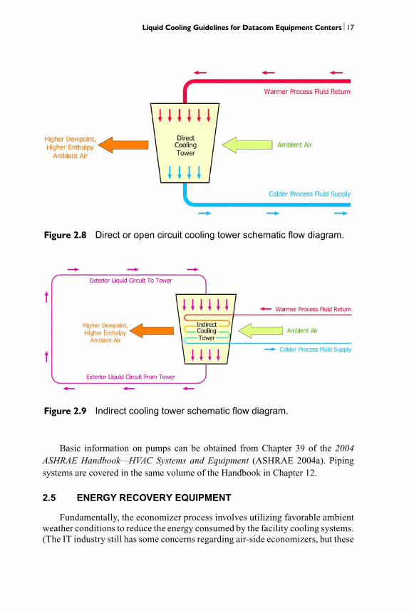
The generic term cooling tower is used to describe both open-circuit (direct-contact) and closed-circuit (indirect-contact) heat-rejection equipment (seeFigures 2.8 and 2.9). The indirect cooling tower is often referred to as a closed circuitfluid cooler or fluid cooler.
Where an open cooling tower is used, a heat exchanger should be considered toisolate the open water loop from the chilled water or other closed loop supplying theequipment cooling system to limit the possibility of fouling.
For data centers or other mission critical facilities, onsite water storage is aconsideration. First, for water-cooled plants with evaporative cooling towers, make-up water storage could be provided to avoid the loss of cooling tower water followinga disruption in water service. For large data centers, the tank size corresponding to24 to 72 hours of onsite makeup water storage could be in the range of 100,000 towell over 1,000,000 gallons. Second, chilled-water storage could provide an emer-gency source of cooling. Placing the chiller plant on a UPS can be very costly;chilled-water storage may offer a short period of cooling to keep chillers off a UPS.Prolonged power outages, however, will still require that chillers be fed from emer-gency generators to maintain operations.
Typically the selection of cooling towers is an iterative process since there area number of variables resulting in the opportunity for trade-offs and optimization.Some of those variables include size and clearance constraints, climate, requiredoperating conditions, acoustics, drift, water usage, energy usage, part-load perfor-mance, etc.
2.4 PUMPS
Pumps and pumping system design should take into account energy efficiency,reliability, and redundancy. It may be possible to design pumps with variable-speeddrives so that the redundant pump is always operational. Ramp-up to full speedoccurs on a loss of a given pump. Use of multiple pumps running at slower speedswill also save energy. Premium efficiency motors should always be specified sincethe payback period will be short with 24/7 operation.
Liquid Cooling Guidelines for Datacom Equipment Centers⏐17
Basic information on pumps can be obtained from Chapter 39 of the 2004ASHRAE Handbook—HVAC Systems and Equipment (ASHRAE 2004a). Pipingsystems are covered in the same volume of the Handbook in Chapter 12.
2.5 ENERGY RECOVERY EQUIPMENT
Fundamentally, the economizer process involves utilizing favorable ambientweather conditions to reduce the energy consumed by the facility cooling systems.(The IT industry still has some concerns regarding air-side economizers, but these
Figure 2.8 Direct or open circuit cooling tower schematic flow diagram.
Figure 2.9 Indirect cooling tower schematic flow diagram.

18⏐ Facility Cooling Systems
are beyond the scope of this liquid cooling document.) Most often this is accom-plished by limiting the amount of energy used by the mechanical cooling (refrig-eration) equipment. Since the use of an economizer mode (or sequence) reducesthe energy consumption while maintaining the design conditions inside the space,another term that is used in the building cooling industry for economizer modeoperation is free cooling.
ANSI/ASHRAE Standard 90.1-2004, Energy Standard for Buildings ExceptLow-Rise Residential Buildings, is a “standard” or “model code” that describes theminimum energy efficiency standards that are to be used for all new commercialbuildings and include aspects such as the building envelope and cooling equipment.This standard is often adopted by an authority having jurisdiction (AHJ) as the codefor a particular locale.
Water-side economizer cycles often use heat exchangers to transfer heat fromthe condenser-water system to the chilled-water system as conditions permit. As itsname suggests, a heat exchanger is a device that relies on the thermal transfer fromone input fluid to another input fluid. One of the fluids that enters the heat exchangeris cooler than the other entering fluid. The cooler input fluid leaves the heatexchanger warmer than it entered, and the warmer input fluid leaves cooler than itentered. Figure 2.10 is a simplistic representation of the process. Figure 2.11 showsa typical installation of plate and frame heat exchangers.
Figure 2.10 Simple overview of the heat exchanger process.

Liquid Cooling Guidelines for Datacom Equipment Centers⏐19
Figure 2.11 Insulated plate and frame heat exchangers.


3
Facility Piping Design
3.1 GENERAL
The piping architecture defines the relationship between the cooling source(plant) and the load (electronic equipment). The architecture should considersimplicity, cost, ease of maintenance, ease of upgrade/change, ease of operation,controls, reliability, energy usage, etc.
Typically the basic options for piping architecture are established and thenreviewed for their effectiveness within the spatial constraints of the facility. Forexample, a loop may look like a good option from a piping architecture perspectivebut the routing paths available may not provide the space and locations needed tocreate effective loops.
This chapter is organized into:
• Spatial considerations, including routing• Basic piping architecture• Piping arrangements for the central plant• Water treatment issues• Earthquake protection
One other important consideration is pipe sizing criteria. Analysis of plant,distribution, and terminal pipe sizes results in trade-offs between capital and oper-ational costs. Larger pipe sizes yield lower water velocities, which, in turn, lowerpumping power (smaller pumps) and operational costs. Generally, velocities shouldbe as high as practical without sacrificing system integrity. (See discussion of veloc-ity limits in Section 5.1.1.3). Typically, increased pumping energy does notoutweigh the lower capital cost or the space savings associated with the smaller pipesizes. Pipe sizing also affects how much additional cooling load can be added to thedata center at a future date. As cooling and power densities continue to grow, datacenters must be scalable to house this future growth. One strategy is to oversize thechilled-water piping plant mains and distribution headers to accommodate future
21

22⏐ Facility Piping Design
load increases. Oversizing these will save energy and allow smaller pumps for muchof the data center’s life.
The chilled-water piping must be planned and designed so the data center canremain operational while adding more computer equipment.
3.2 SPATIAL CONSIDERATIONS
Usually the spatial considerations start by determining what piping can belocated in the data center and where. Some examples of stakeholder concerns/pref-erences are:
• No overhead piping, minimal overhead piping, or no constraint on overheadpiping other than to avoid routing directly above electronic equipment.
• All piping mains and pipes above a certain size can be run in the data center orare confined to pipe galleries, chases, troughs, utility pits, etc.
The spatial constraints do not just apply to routing but also to the accessibilityof valves and terminations as well as the impact of piping penetrations through fire-walls. Stakeholder piping location preferences combined with the physicalconstraints of the facility often have as much or more influence on the piping archi-tecture as any other influence, such as operations, energy, or redundancy.Consideration should be given to laying out large piping first so as to minimizepressure drop, e.g., large radius bends, few changes of direction, etc. Then arrangepumps, chillers, etc., to tie into the piping with minimal changes of direction. Thiswill likely result in chillers and pumps arranged in less than a linear fashion—perhaps at 45° instead of 90°.
Although each layout and design is different, a good starting point is to allocatecross-sectional dimensions that are twice the pipe diameter. Some examples:
• If the pipe is 6 in. in diameter, then allow 2 × 6 in. or 12 × 12 in. in cross section.• If the pipe is 18 in. in diameter, then allow 2 × 18 in. or 36 × 36 in. in cross section.
These allocations are to allow for the pipe flanges, pipe guides/supports, valvehandles, etc. Also, the piping design must consider expansion and contraction aswell as seismic considerations. For example, the piping may be stored and installedin an ambient temperature of 90°F (32°C) and operate at 45°F (7°C). The differentialtemperature (90°F – 45°F = 45°F [25°C]) can cause significant movement duringsystem startup and cooldown.
3.3 BASIC PIPING ARCHITECTURE
Inherent to the concept of liquid cooling is extending the infrastructure thatcontains the cooling media to an area local to the datacom equipment. In addition,the infrastructure delivery method is typically at a much finer granularity (i.e., manymore points of connection) based on the terminal use of the liquid. Cooling equip-

Liquid Cooling Guidelines for Datacom Equipment Centers⏐23
ment may be serving a few racks, a single rack, or perhaps even multiple componentswithin a single rack.
The infrastructure itself is typically a copper or steel piping network. Manydifferent piping architectures and flow principles can be used to extend the pipingnetwork to the rack and the increased points of connection while at the same timeproviding an overall system that is consistent with the necessary reliability andflexibility of a datacom facility. The following group of diagrams within thissection represent some of the different piping architectures and flow principlesthat can be used.
Direct Return (Figure 3.1)
A direct return system is the most basic type of piping system and is used intraditional HVAC design where there are a reduced number of connection points. Inthis system, the supply and return piping is fed in a radial manner and the loads thatare closest to the cooling plant have the shortest supply piping lengths and the short-est return piping lengths.
Figure 3.1 Example of direct return flow principle.

24⏐ Facility Piping Design
However, the direct return method, when used in an application that has manyclose connection points, may require an excessive amount of balancing valves toensure proper system operation. This is due to the variation in supply and returnpiping lengths to a given load.
Advantages
1. Least expensive to construct, uses a minimal amount of pipe, valves, and fittings.2. Simplest to operate and understand.
Disadvantages
1. Least reliable since only one source of cooling exists.2. No redundancy in piping to the load. Any pipe failure or leak or future addition
could jeopardize system availability.3. May require additional balancing valves.
Reverse Return (Figure 3.2)
The objective of the reverse return flow principle is to inherently create a pipingnetwork with an element of self-balancing. This is achieved by having the loadssupplied by piping closest to the cooling plant also be the loads that are at the mostremote end of the return piping and vice versa. This is achieved by essentially havingthe flow in the return piping parallel the flow in the supply piping as it feeds the vari-ous loads around the building. This results in the combined length of supply andreturn piping for any given load being approximately equal, which creates a systemthat can be considered self-balancing.
Advantages
1. Simple to operate and understand.2. Self-balancing.
Disadvantages
1. Less reliable; again, only one source of cooling.2. No redundancy in pipe or chilled-water routes. Routine maintenance or system
expansion could require complete system shutdown.3. A little more expensive to install than direct return (i.e., more piping required).
Looped Mains Piping Schemes
The remaining piping architecture examples illustrated in this section involvethe use of looped piping mains. Looped piping mains involve a closed loop that istapped at various points to feed loads. The flow of liquid within the loop can occurin two directions from the source and, in theory, there is a “no-flow zone” near themidpoint of the loop.

Liquid Cooling Guidelines for Datacom Equipment Centers⏐25
More importantly, the architecture of looped piping mains also allows for asection of main piping to be isolated for maintenance or repair. Loads that weredownstream of the isolated section can then be backfed from the other side of thelooped mains to allow for greater online availability of the cooling system.
Various piping architectures can be used to create a loop design. These varia-tions allow a system to attain different levels of isolation, different hydraulic char-acteristics, and different levels of modularity. The following diagrams illustratesome examples of looped piping architectures.
Single-Ended Loop with Direct Feed (Figure 3.3)
A single-ended loop has a single point of connection (supply and return piping)to the plant. The piping is typically looped within the datacom area and, in this partic-ular configuration, the loads are directly fed from the mains’ loop piping.
Figure 3.2 Example of reverse return flow principle.

26⏐ Facility Piping Design
A popular application of this piping architecture is for an air-cooled CRAC unitbased cooling system, where CRAC units are located around the perimeter of thedatacom area.
Advantages
1. Self-balancing.2. Increased reliability over direct and reverse returns systems with two piping
routes to the load.
Figure 3.3 Single-ended loop with direct feed.

Liquid Cooling Guidelines for Datacom Equipment Centers⏐27
3. Individual pipe sections and future equipment installations are serviceablewithout system shutdown.
Disadvantages
1. Increased complexity and understanding.2. Increased installation costs.
Single-Ended Loop with Common Cross Branches (Figure 3.4)
Similar to the previous example (Figure 3.3), the same single-ended loop archi-tecture is used. The difference is in the connection of the loads, which are now indi-rectly fed from cross-branch piping connected at two locations to the mains’ loop.The cross-branch piping is said to be common since it is used by multiple loads onboth sides of its route as a supply and return flow path.
This method not only allows for a bidirectional flow of liquid in the mains butalso within each cross branch. As such, it provides multiple paths for flow to reachthe majority of the loads should a section of the mains’ loop or the cross branch needto be isolated for reasons of maintenance or repair.
Advantages
1. Increased reliability with multiple piping routes to load.2. Self-balancing.3. Used primarily for water-cooled rack units.4. Individual pipe sections and future equipment installations are serviceable
without system shutdown.
Disadvantages
1. Increased installation costs.2. Increased operational complexity.
Single-Ended Loop with Dedicated Cross Branches (Figure 3.5)
The same single-ended loop is used here as with the previous two examples(Figures 3.3 and 3.4) and the same cross-branch piping as in the previous example(Figure 3.4).
Now, however, the indirect connections of the loads are supplied from anincreased number of cross-branch pipes. This allows for an increase in granularityof the loads and, therefore, an increased level of reliability (i.e., the isolation of asection of cross-branch piping will not impact as many loads since there are fewerconnections per cross branch).

28⏐ Facility Piping Design
As is apparent from the diagram, this architecture involves many more crossbranches, so the increased granularity needs to be evaluated against increased costand hydraulic/control complexity.
Advantages
1. Increased reliability with multiple piping routes to load.
2. Self-balancing.
3. Individual pipe sections and future equipment installations are serviceablewithout system shutdown.
Figure 3.4 Single-ended loop with common cross branches.

Liquid Cooling Guidelines for Datacom Equipment Centers⏐29
Disadvantages
1. Increased installation costs.2. Increased operational complexity.
Double-Ended Loop with Direct Feed (Figure 3.6)
The only difference between the single-ended loop (shown in Figure 3.3) andthe double-ended loop (shown in Figure 3.6) is that in this piping architecture thereare two connections to the plant, which eliminates the single point of failure thatexists for all single-ended loop piping configurations (e.g., if a need exists to isolate
Figure 3.5 Single-ended loop with dedicated cross branches.

30⏐ Facility Piping Design
the piping between the connection to the plant and upstream toward the plant itself,this method will still allow cooling to all loads via the second connection).
To illustrate an even greater level of reliability, consider the second connectionto the loop to be from an operationally independent plant. These independent plantscould even be in geographically different locations within the same facility.
Advantages
1. High reliability.
2. Redundant piping routes to load and a second cooling supply and return mainsfrom the plant.
3. Redundant cooling supply and return piping from a second central plant.
Figure 3.6 Double-ended loop with direct feed.

Liquid Cooling Guidelines for Datacom Equipment Centers⏐31
4. Individual pipe sections and future equipment installations are serviceablewithout system shutdown.
5. Self-balancing.
Disadvantages
1. Increased installation costs.2. Increased operational complexity.
Double-Ended Loop with Common Cross Branches (Figure 3.7)
As stated previously, the difference between this piping architecture and thesingle-ended loop with common cross branches (shown in Figure 3.4) is that twoconnections to the plant are made to eliminate the single point of failure.
Figure 3.7 Double-ended loop with common cross branches.

32⏐ Facility Piping Design
Advantages
1. High reliability.2. Redundant piping routes to load and a second cooling supply and return mains
from the plant. 3. Redundant cooling supply and return piping from a second central plant.4. Individual pipe sections and future equipment installations are serviceable
without system shutdown. 5. Self-balancing.
Disadvantages
1. Increased installation costs.2. Increased operational complexity.
Double-Ended Loop with Dedicated Cross Branches (Figure 3.8)
Similarly, the principal difference between this piping architecture and thesingle-ended loop with dedicated cross branches (shown in Figure 3.5) is that twoconnections to the plant are made to eliminate the single point of failure.
Advantages
1. High reliability.2. Redundant piping routes to load and a second cooling supply and return mains
from the plant. 3. Redundant cooling supply and return piping from a second central plant.4. Individual pipe sections and future equipment installations are serviceable
without system shutdown. 5. Self-balancing.
Disadvantages
1. Increased installation costs.2. Increased operational complexity.
3.4 PIPING ARRANGEMENTS FOR THE COOLING PLANT
The cooling plant equipment can be configured various ways. For example, thechillers can be configured in series or parallel and have different preferential loadingschemes. The pumping and flow can be configured as constant flow, stepped variableflow, or variable flow. The building owner or occupant will have to perform an engi-neering analysis to determine which configuration is best for their data center.
Figure 3.9 shows a typical decoupled or condenser-water system/chilled-watersystem pumping configuration.

Liquid Cooling Guidelines for Datacom Equipment Centers⏐33
3.4.1 CHWS Pipe Sizing
The pipe conveyance has to support real load rather than an average bulk loadon the raised floor. Today’s data center has an eclectic grouping of various loadsranging from cross-connect racks (no-load) to blade servers. The CHWS pipe workmust provide cooling at hot spot areas during the life of the data center. Since theseareas might change with new equipment over time, flexibility to provide hotter areaswith cooling must be oversized in the CHWS distribution. Example: if the averageload is at a design density of 100 W/ft2, the CHWS distribution should be able tosupply any local area of the raised floor with 175–200 W locally. In today’s envi-ronment of changing technology, all CHWS piping should plan for a series of addi-tional water taps off the distribution to serve the future requirements for auxiliarycooling equipment.
Figure 3.8 Double-ended loop with dedicated cross branches.

34⏐ Facility Piping Design
3.4.2 Loop Isolation Valve Failures
The basis for reliable service in the mechanical plant and pipe work uses loopisolation valves to isolate the operating system from the repair or expansion. If theisolation valve itself fails, both sides of the loop are then exposed to the next isolationvalves. Depending on the design configuration, this might include the redundantpump or chiller and render the capacity of the system below critical load. Therefore,the entire loop strategy relies on the loop isolation valve reliability and service life.To remove this single point of failure from the system, either a double-pipe system(independent of the first system) or a double set of isolation valves is used in loca-tions where a single valve can affect critical load.
Figure 3.9 Condenser water system/chilled-water system distribution piping.

Liquid Cooling Guidelines for Datacom Equipment Centers⏐35
3.5 WATER TREATMENT ISSUES
Whenever an oversized pipe system with redundant pathways and expansionsections is prebuilt for future service and then installed into a data center, the oper-ation of the center needs water treatment to protect the system. Pipe walls interactwith the water they circulate. Water treatment includes testing and injecting chem-icals to prevent the pipe walls from corrosion. Pipe loops may not have any flow atall for extended periods, and expansion sections may never have flow. The life of thetreatment chemicals is approximately 30 days (depending on strength and waterquality). Where pipe flow is low or is not disturbed, fouling and corrosion may occur.Periodically the flow in these pipes must be accelerated to full flow for a short timeeach month to re-protect the pipe walls. In stagnant segments, the water flow mustbe directed to the areas to re-coat those surfaces. Allowing the operations staff togain experience shifting cooling water conveyance is also important for operationalreadiness in the event of a leak. The expansion legs should have a circulation jumper(1/4 in. bypass) with valves to allow a flushing of these pipes monthly to keep protec-tion and fouling under control. The entire process can be automated if loop isolationand VFD drives can be controlled by the automation system.
3.6 EARTHQUAKE PROTECTION
Depending on the design area and the risk aversion of the data center insuranceunderwriters, the mechanical and fire protection pipes over 4 in. in diameter maycome under bracing requirements for earthquake protection. A qualified structuralengineer will be required to design for these requirements.


4
Liquid CoolingImplementation forDatacom Equipment
Chapter 1 briefly describes several examples of different implementations ofliquid cooling technologies. More importantly, Chapter 1 clearly defines air-cooledand liquid-cooled datacom equipment, as well as air-cooled and liquid-cooled racksor cabinets. The following sections provide detailed descriptions of the variousliquid cooling implementations. Section 4.1 illustrates cooling at the rack/cabinetlevel, showing several common configurations for air, liquid, and combination(air + liquid) cooling. A more detailed look inside the rack/cabinet is provided inSection 4.2, which discusses air- and liquid-cooled datacom equipment. Becauseliquid cooling often employs a coolant distribution unit (CDU) to condition andcirculate the coolant, Section 4.3 provides a detailed overview of this system. Thewords fluid and coolant are used interchangeably throughout. Throughout this chap-ter, the liquid lines are shown in the figures as a solid or dashed line and airflow isrepresented with arrows that contain dots.
4.1 OVERVIEW OF LIQUID-COOLED RACKS AND CABINETS
A rack or cabinet is considered to be liquid-cooled if liquid must be circulatedto and from the rack or cabinet for operation. The following figures illustrate coolingat the rack/cabinet level. The first is a basic air-cooled rack. The remaining figuresshow other options that utilize liquid cooling or a combination of air cooling andliquid cooling. The figures in this section all show the coolant supply and return linesunder the raised floor. Other facility implementations may allow such lines to berouted above the floor or from the ceiling. Coolant supply and return connections forthe rack/cabinet can be from the base, side, or top.
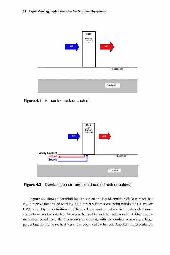
Figure 4.1 shows a purely air-cooled rack or cabinet implementation. While thisbook’s focus is on liquid cooling, this figure provides a baseline with which the vastmajority of datacom center operators are familiar. It should be noted that while thefigures all show a front-to-back configuration for the airflow and the rack, it can alsobe configured as front-to-top or front-to-back-and-top (ASHRAE 2004b).
37
38⏐ Liquid Cooling Implementation for Datacom Equipment
Figure 4.2 shows a combination air-cooled and liquid-cooled rack or cabinet thatcould receive the chilled working fluid directly from some point within the CHWS orCWS loop. By the definitions in Chapter 1, the rack or cabinet is liquid-cooled sincecoolant crosses the interface between the facility and the rack or cabinet. One imple-mentation could have the electronics air-cooled, with the coolant removing a largepercentage of the waste heat via a rear door heat exchanger. Another implementation
Figure 4.1 Air-cooled rack or cabinet.
Figure 4.2 Combination air- and liquid-cooled rack or cabinet.

Liquid Cooling Guidelines for Datacom Equipment Centers⏐39
could have the coolant delivered to processor spot coolers (some form of cold plate),with the balance of the electronics being air-cooled. The descriptions provided are twoof many different implementations and should not be understood as the only possibleimplementations. Further details of the implementation within the rack, cabinet, ordatacom equipment are provided in Section 4.2. It is important to note that this config-uration is susceptible to condensation because there is no CDU in place to raise thetemperature of the chilled fluid above dew point, if necessary.
Figure 4.3 shows a purely liquid-cooled rack or cabinet. One example of suchan implementation may have all the electronics in the rack or cabinet conduction-cooled via cold plates. This cooling method could deploy water, refrigerant, or otherdielectric coolant as the working fluid. Another implementation may have all theelectronics cooled via liquid flow-through (e.g., forced flow boiling), jet impinge-ment, spray cooling, or another method that deploys a dielectric coolant to directlycool the electronics. Yet another implementation would include a totally enclosedrack that uses air as the working fluid and an air-to-liquid heat exchanger. Furtherdetails are provided in Section 4.2. Similar to Figure 4.2, the configuration inFigure 4.3 is also susceptible to condensation because there is no CDU in place toraise the temperature of the chilled fluid above dew point, if necessary.
Figure 4.4 shows a combination air-cooled and liquid-cooled rack or cabinetwith an external CDU. The CDU, as the name implies, conditions the technologycooling system (TCS) or datacom equipment cooling system (DECS) coolant in avariety of manners and circulates it through the TCS or DECS loop to the rack, cabi-net, or datacom equipment. This implementation is similar to that of Figure 4.2, withthe exception that there is now a CDU between the facility (CHWS or CWS) levelsupply of chilled fluid and the rack or cabinet. This implementation allows the CDU
Figure 4.3 Liquid-cooled rack or cabinet (side view).

40⏐ Liquid Cooling Implementation for Datacom Equipment
to condition the coolant delivered to the rack or cabinet to a temperature above thefacility’s dew point.
Figure 4.5 shows a purely liquid-cooled rack or cabinet implementation. Thisimplementation is similar to that of Figure 4.3, as well as Figure 4.4, where an exter-nal CDU is included.
Figure 4.4 Combination air- and liquid-cooled rack or cabinet withexternal CDU.
Figure 4.5 Liquid-cooled rack or cabinet with external CDU.

Liquid Cooling Guidelines for Datacom Equipment Centers⏐41
Figures 4.6 and 4.7 are the final implementations to be discussed in this section.These implementations have a lot in common with the implementations ofFigures 4.4 and 4.5, respectively. One obvious difference is the fact that the racks orcabinets shown in Figures 4.6 and 4.7 now possess dedicated CDUs, i.e., internalCDUs. The CDUs are shown at the bottom of the rack, but other configurations could
Figure 4.6 Combination air- and liquid-cooled rack or cabinet withinternal CDU.
Figure 4.7 Liquid-cooled rack or cabinet with internal CDU.

42⏐ Liquid Cooling Implementation for Datacom Equipment
include them on the side or top of the rack. This implementation provides more flex-ibility to the datacom center operator in that the racks or cabinets can now conditiontheir coolants to vastly different conditions as a function of the workload or the elec-tronics within. Another benefit is that different coolants (e.g., water, refrigerant,dielectric) can now be deployed in the different racks as a function of workload orelectronics type. Additional detail is provided in Section 4.2.
4.2 OVERVIEW OF AIR- ANDLIQUID-COOLED DATACOM EQUIPMENT
While Section 4.1 dealt with the external interaction between the building infra-structure and the rack or cabinet, this section examines the possible liquid coolingsystems internal to the rack or cabinet. Described within this section are seven data-com cooling configurations, which represent the most commonly used configura-tions. Other configurations are possible but are not examined here for brevity’s sake.
The systems remove heat from the rack or cabinet by means of a fluid whosechemical, physical, and thermal properties are conditioned by a CDU for thatpurpose. The conditioned fluid may be water, an antifreeze mixture, dielectricfluid, or refrigerant.
Figure 4.8 shows a rack or cabinet with combined air and liquid cooling. Thecomputer room air and the conditioned liquid each remove a part of the heat load.In this configuration, air is the only coolant entering the datacom equipment. The air-to-liquid heat exchanger extracts heat from the air that is either entering or leavingthe datacom equipment and, as a result, reduces the heat load on the computer roomair conditioning and reduces hot air recirculation. The heat exchanger may bemounted on the rack or cabinet doors or in any other location along the airstream.
Figure 4.8 Open air-cooled datacom equipment in an air/liquid-cooled rack.

Liquid Cooling Guidelines for Datacom Equipment Centers⏐43
Whichever the case, care should be taken to consider heat exchanger effectivenessand condensation, especially with configurations where the heat exchanger isupstream from the datacom equipment. Finally, if the air pressure drop across theheat exchanger is sufficiently low, no additional fans will be required to achieve thenecessary airflow rate.
Figure 4.9 shows an enclosed cabinet where air is again the only coolant enter-ing the datacom equipment, but here computer room air is excluded, and the entireheat load (apart from heat loss though panels) is removed by the conditioned fluid.Additional fans will probably be required to drive sufficient airflow through thesystem. To cool the datacom equipment, this configuration requires the sameamount of cooling air as the configuration shown in Figure 4.1. The fans and theheat exchanger may be located in various positions. For example, the fans may bein a duct on the rear door, and the heat exchanger may be at the bottom of the cabi-net. The objectives are to achieve sufficient airflow to extract the total heat loadand to achieve an airflow distribution that avoids uneven cooling and “hot spots”within the cabinet.
Figure 4.10 illustrates a rack or cabinet where the internal heat transfer is byliquid only. The heat exchanger and pump are shown as “optional” to recognize thecase where the facility working fluid from the CHWS or CWS loop is sufficientlyconditioned to allow direct entry to the datacom units. Unless there is a local CDUassociated with the cabinets, one important benefit of the CDU, namely, the limitingof fluid leakage volume, is lost.
Figure 4.11 shows the addition of computer room air cooling to a Figure 4.10system. In view of the variety of heat sources and their different form, we couldexpect this to be a more frequent configuration since airflow through complex orheterogeneous geometries is easier to implement with air than with liquids.
Figure 4.9 Closed air-cooled datacom equipment in a liquid-cooled cabinet.

44⏐ Liquid Cooling Implementation for Datacom Equipment
The arrangement in Figure 4.12 goes one step further. Like Figure 4.11, it showsa combination of air and liquid cooling, but now the air is a closed loop that stayswithin the cabinet. The air is cooled by a separate heat exchanger. This configurationmay represent a cabinet housing multiple pieces of datacom equipment, some liquid-cooled and others air-cooled. It may also represent datacom equipment with somecomponents that are liquid-cooled (e.g., the CPU) and other components that are air-cooled (e.g., the power supplies).
Figure 4.10 Liquid-cooled datacom equipment in a liquid-cooled rack.
Figure 4.11 Open air- and liquid-cooled datacom equipment in an air/liquid-cooled rack.

Liquid Cooling Guidelines for Datacom Equipment Centers⏐45
Figures 4.13 and 4.14 illustrate the application of vapor-compression cycle heattransfer within the rack or cabinet. Figure 4.13 employs an internal DECS loop, andin Figure 4.14 air is the working fluid between the datacom equipment and the vapor-compression system.
In all of the systems listed above, the principal heat “sink” is the facility condi-tioned fluid in the CHWS (chiller) or CWS loop, in some cases assisted by computerroom conditioned air. When using a DX system, the facility conditioned fluid wouldbe liquid refrigerant. When significant heat loads are removed by conditioned fluids,the computer room air temperature may be allowed to rise, presenting a morecomfortable operating environment. However, the current focus on fluids is drivenprimarily by escalating heat dissipations and the subsequent risk of thermal failureand shortened life span that are associated with high chip operating temperatures, aswell as lower energy costs because liquid solutions are more efficient than air.
4.3 OVERVIEW OF COOLANT DISTRIBUTION UNIT (CDU)
The coolant distribution unit (CDU), as the name implies, conditions the TCS orDECS coolant in a variety of manners and circulates it through the TCS or DECS loopto the rack, cabinet, or datacom equipment (see Figure 1.1 for cooling loop descrip-tions). For example, the CDU can condition the coolant for temperature and cleanliness(particulate and chemical). The CDU implementations shown in Figures 4.15–4.20 alldemonstrate coolant temperature control via the heat exchanger. It should be noted thatcoolant temperature control can also be achieved via heat exchanger bypass. The CDUcan also be designed to condition the coolant if the TCS or DECS coolant is a refrigerantor dielectric. The rack or facility coolant supplied to the CDU can be refrigerant
Figure 4.12 Closed air- and liquid-cooled datacom equipment in a liquid-cooled rack.

46⏐ Liquid Cooling Implementation for Datacom Equipment
supplied by a DX system. The functionality of the CDU will depend, in large part, uponthe coolant that is being conditioned and the level at which the CDU is implemented(i.e., internal to the datacom equipment, internal to the rack/cabinet, or at facility leveland external to the rack). In all cases, the CDU includes a pump or compressor to circu-late the fluid through the coolant loop. While all of the figures show counterflow heatexchangers, other types are possible.
Figure 4.13 Liquid-cooled datacom equipment in a liquid-cooled rack usinga vapor-compression system.
Figure 4.14 Air-cooled datacom equipment in a liquid-cooled cabinet usinga vapor-compression cycle.

Liquid Cooling Guidelines for Datacom Equipment Centers⏐47
The CDU provides a number of important benefits, as follows:
• Prevention of condensation: It provides an opportunity for temperature con-ditioning, which could allow the coolant to be delivered to the electronicsabove the dew point.
• Isolation: It may allow the electronics to be isolated from the harsher facilitywater in the CHWS or CWS loop. The loop supplied by the CDU also utilizesa lower volume of coolant, so a coolant leak is less catastrophic.
• Coolant flexibility: The separate loop associated with the CDU allows usersthe flexibility to use any number of coolants.
• Temperature control: The separate loop associated with the CDU allowsusers the flexibility of running the electronics at a desired temperature. Thistemperature can be above, at, or below the dew point.
Figures 4.15–4.20 illustrate the breadth of current implementations of CDUs.While not shown, it is implied that some form of quick disconnect (or quick couplingand a ball valve) is implemented at all points where coolant crosses the “CDUboundary” line, which is indicated by a dashed-dotted line around the CDU. The useof quick disconnects allows for low loss of coolant and facilitates replacement of aCDU in the event of a catastrophic failure. It is important to keep in mind that thereare many possible implementations of CDUs outside of those shown inFigures 4.15–4.20. Figures 4.15 and 4.16 illustrate implementations internal to thedatacom equipment. Figures 4.17 and 4.18 illustrate implementations internal to therack/cabinet. Figures 4.19 and 4.20 illustrate implementations external to the rack/cabinet and at the facility level. Further descriptions follow.
Figure 4.15 shows an implementation of a CDU internal to the datacom equip-ment. The datacom equipment rejects the heat from its electronics via a cold platethat docks with another rack/cabinet-based cold plate. At a very basic level, the CDUconsists of a cold plate, an accumulator (or a reservoir), and a pump (or multiplepumps for redundancy). The operation of the pump is regulated by some form ofcontroller, which is in communication with one or more sensors within the CDU.The data from the sensors are used to control the level of operation of the CDU.
Similarly to Figure 4.15, Figure 4.16 illustrates an internal datacom equipmentimplementation of a CDU. The basic functionality for this implementation is similarto that for Figure 4.15, with the exception of the use of a liquid-to-liquid heatexchanger to reject the datacom equipment heat. In other implementations, the CDUcould deploy a liquid-to-air heat exchanger.
Figure 4.17 shows a CDU implementation internal to the rack or cabinet, asshown in Figures 4.6 and 4.7. The CDU shown consists of a liquid-to-liquid heatexchanger, an accumulator (or a reservoir), a pump (or multiple pumps for redun-dancy), a chemical bypass filter for solvent and water removal, and a particulatefilter. Applications of an internal CDU will often use refrigerant or dielectric as the

48⏐ Liquid Cooling Implementation for Datacom Equipment
cooling fluid. These fluids necessitate the use of additional filters. This implemen-tation also interfaces with one or more controllers that control the operation of theCDU. The controllers can use sensor inputs at the datacom equipment, rack, or facil-ities level. While a liquid-to-liquid heat exchanger is shown, this implementationcould also deploy a liquid-to-air heat exchanger.
Similarly to Figure 4.17, Figure 4.18 illustrates the internal implementation ofa CDU at the rack/cabinet level, as shown in Figures 4.6 and 4.7. The basic func-tionality of this CDU is similar to that shown in Figure 4.17, with the main differencebeing the use of a vapor-compression system. A key benefit of a vapor-compressionsystem is that it allows the user to drop the temperature of the working coolant belowthat of the coolant to which it is rejecting the heat from the electronics. Unique tothe vapor-compression system, a compressor (or multiple ones for redundancy) andan expansion valve are used. While a liquid-cooled condenser is shown, an air-cooled condenser could also be deployed.
Figure 4.15 Internal datacom equipment-based CDU that utilizes a dockingstation and cold plates.

Liquid Cooling Guidelines for Datacom Equipment Centers⏐49
Figure 4.16 Internal datacom equipment-based CDU that utilizes a liquid-to-liquid heat exchanger.
Figure 4.17 Internal rack or cabinet-based CDU that utilizes a liquid-to-liquid heat exchanger.

50⏐ Liquid Cooling Implementation for Datacom Equipment
Figure 4.19 shows a CDU implementation external to the rack and at the facilitylevel, as shown in Figures 4.4 and 4.5. This form of CDU can supply cooling fluidto a single rack or a row of racks. In its most basic form, this CDU consists of a liquid-cooled condenser, a pump (the additional space typically allows for redundantpumps), and an expansion tank. The CDU communicates with one or more control-lers at the datacom equipment, rack/cabinet, and facility levels, which can controlthe operation of the CDU. It is possible, but probably not likely, that an air-cooledcondenser could be deployed. This is probably not likely due to the amount of heatthat has to be rejected. One of the key benefits of this type of implementation is thatit isolates the racks/cabinets and datacom equipment from the facility water in theCHWS or CWS loop, which tends to be much harsher on the internal materials.
Figure 4.20 shows the implementation of a CDU external to the rack or at thefacility level, as shown in Figures 4.4 and 4.5. The basic functionality is similar tothat of Figure 4.19, with the key difference being the use of a vapor-compressionsystem. Similar to Figure 4.19, the basic vapor-compression system uses a compres-sor (or multiple ones for redundancy), a liquid-cooled condenser, and an expansionvalve. This implementation of the CDU can also communicate with one or morecontrollers at the datacom equipment, rack/cabinet, and facility levels. Similar to theimplementation of Figure 4.20, it is possible, but probably not likely, that an air-cooled condenser could be deployed. This implementation also isolates the racks/cabinets and datacom equipment from the facility water in the CHWS or CWS loop.
The temperature in the datacom equipment can rise very, very quickly if theCDU fails. Therefore, CDU implementations need to be redundant and fault-toler-
Figure 4.18 Internal rack or cabinet-based CDU that utilizes a liquid-cooledcondenser and a vapor-compression system.

Liquid Cooling Guidelines for Datacom Equipment Centers⏐51
ant. All of the strategies discussed in Section 2.1.5 regarding CRAC availability andredundancy apply to the CDU. Multiple CDUs should be implemented to eliminatedowntime from mission critical installations. The chiller supplying the cooling fluidto the CDU also needs to be redundant and fault-tolerant to ensure it is alwayssupplying cooling water to the CDU.
Figure 4.19 Facility-based CDU that utilizes a liquid-cooled condenser.
Figure 4.20 Facility-based CDU that utilizes a liquid-cooled condenser anda vapor-compression system.

52⏐ Liquid Cooling Implementation for Datacom Equipment
The CDU vendor also must design the CDU to be fault-tolerant. For instance,the coolant pump in the CDU is most likely the point of failure. Most systems willhave redundant pumps. The pump will either alternate on a relatively short-termbasis (weekly or monthly) or one pump will be the primary pump and a secondarypump will be tested periodically to make sure it is operational. The pumps will likelyhave isolation valves so that the nonfunctional pump can be isolated for replacementwithout bringing the entire CDU (and associated datacom equipment) down forrepair. On smaller systems that may not accommodate dual pumps, the vendor willselect a pump with a long life. In this situation, it is expected that the CDU will beupgraded before the pump wears out. Power to the CDU also needs to be backed upby a UPS. This will allow the datacom equipment to continue running or to shutdown gracefully in the event of a power outage.

5
Liquid Cooling Infrastructure Requirements forChilled-Water Systems
This section defines interface requirements between the facilities controlled bythe building facility operators and the datacom equipment controlled by the datacommanufacturers. Demarcation lines for the CHWS are provided to describe wherethese interfaces occur in relationship to the datacom equipment and its locationwithin the data center or telecom room.
5.1 BUILDING FACILITY CHILLED-WATER SYSTEMS (CHWS)
Figures 5.1 and 5.2 show the interfaces for an external liquid-cooled rackwith remote heat rejection. The interface is located at the boundary at the facilityCHWS loop and does not impact the TCS or DECS loops, which will becontrolled and managed by the cooling equipment and datacom manufacturers.However, the definition of the interface at the CHWS loop affects both the data-com equipment manufacturers and the facility operator where the datacom equip-ment is housed. For that reason all of the parameters that are key to this interfacewill be described in detail in this section. Also, note that the coolant loops in theCDU are typically separate.
5.1.1 Chilled-Water Details
The majority of liquid cooling applications are anticipated to be water or waterplus additives (e.g., propylene glycol, etc.). The following sections focus on theseapplications. Different design and operational requirements will certainly berequired for alternate liquids, e.g., refrigerants or dielectrics (see Section 5.2 for non-chilled-water systems). Datacom equipment that requires a supply of chilled waterfrom the data center facilities will typically adhere to the operational requirementscontained within this section.
5.1.1.1 Operational Requirements. The datacom equipment should generallyaccommodate chilled-water supply temperatures that range from 40°F to 60°F (4°Cto 16°C). The recommended nominal is 50°F (10°C) water. The actual CHWS loop
53

54⏐ Liquid Cooling Infrastructure Requirements for Chilled-Water Systems
Figure 5.1 Combination air- and liquid-cooled rack or cabinet with externalCDU (same as Figure 4.5).
Figure 5.2 Combination air- and liquid-cooled rack or cabinet with internalCDU (same as Figure 4.6).

Liquid Cooling Guidelines for Datacom Equipment Centers⏐55
temperature may be set by a campus-wide operational requirement. It also may bethe optimum of a balance between lower operational cost using higher-temperaturechilled-water systems versus a lower capital cost with low-temperature chilled-water systems. Consideration of condensation prevention is a must. In the CHWSloop, insulation will typically be required. In the TCS and DECS loops, condensa-tion control is typically provided by an operational temperature above the dew point.
The chilled-water supply temperature measured at the inlet of the datacomequipment or the CDU should not exceed a rate of change of 5°F (3°C) per five-minute cycle. This may require that the infrastructure be on UPS electrical supply.
The maximum allowable water pressure supplied to the TCS and DECS loopsshould be 100 psig (690 kPa) or less.
The chilled-water flow rate requirements and pressure-drop values of thedatacom equipment vary, depending on the chilled-water supply temperature andthe percentage of treatment (antifreeze, corrosion inhibitors, etc.) in the water.Manufacturers will typically provide configuration-specific flow rate and pressuredrop values that are based on a given chilled-water supply temperature (nominally50°F [10°C]).
The CHWS should incorporate a water flow control valve, typically a two-waymodulating water flow valve. Generally, these valves are open and modulating whenthe datacom equipment is operating and fully closed when the datacom equipmentis powered off. Depending on the design of the chilled-water system, a method ofbypassing chilled water or de-energizing chilled-water pumps when the datacomequipment is not operating may be needed. Alternatively, for systems that mustmaintain a constant flow rate, three-way valves can provide this same function.
The flow rate for chilled water to be delivered to the datacom equipment orthe CDU can be determined from flow rate tables provided by the manufacturerof such equipment.
5.1.1.2 Chilled-Water Flow Rates. Chilled-water flow rates are shown inFigure 5.3 for given heat loads and given temperature differences. Temperaturedifferences typically fall between 9°F and 18°F (5°C and 10°C).
Fouling factors refer to an additional thermal resistance that occurs when theheat transfer surfaces have deposits built up over a period of time. These deposits arepresent in the coolant water. The higher the fouling factor becomes, the higher therequired chilled-water flow rate becomes.
Typical fouling factors derived from m2°C/W are:
Muddy or silty 0.0006Hard (over 15 grains/gal) 0.0006City water 0.0002Treated cooling tower 0.0002
Refer to the list of references on how to apply these factors in sizing heat exchangers.

56⏐ Liquid Cooling Infrastructure Requirements for Chilled-Water Systems
5.1.1.3. Velocity Considerations. The velocity of the water in the CHWS looppiping must be controlled to ensure mechanical integrity is maintained over the lifeof the system. Velocities that are too high can lead to erosion, sound/vibration, waterhammer, and air entrainment. Particulate free water will have less water velocitydamage to the tubes and associated hardware. Table 5.1 provides guidance onmaximum chilled-water piping velocities for systems that operate over 8,000 hoursper year. Flexible tubing velocities should be maintained below 5 ft/s (1.5 m/s).
5.1.1.4. Liquid Quality/Composition. Table 5.2 identifies the water qualityrequirements that are necessary to operate the liquid-cooled system. The reader isencouraged to reference Chapter 48 of the 2003 ASHRAE Handbook—HVAC Appli-cations. This chapter, titled “Water Treatment,” provides a more in-depth discussionabout the mechanisms and chemistries involved.
5.1.1.4.1 Water Quality Problems. The most common problems in coolingsystems are the result of one or more of the following causes:
• Corrosion: the dissolution of metals by water. Corrosion can be in the formof general corrosion (entire surface) or localized corrosion (pitting or stress),
Figure 5.3 Typical chiller water flow rates for constant heat load.

Liquid Cooling Guidelines for Datacom Equipment Centers⏐57
which causes metal perforation and rapid failure. The primary metals that cancorrode in the loop are aluminum, stainless steel, and copper. Corrosion of steeland copper is often of a general nature, although the majority of system failuresresult from localized corrosion and not general corrosion. Corrosion of alumi-num is often in the form of pitting. Typically, pH values below neutral (pH < 7)add significantly to the corrosion of typical metal piping systems. Corrosion isalso driven by high levels of chlorides, sulfides, and sulphates in the loop.
• Fouling: insoluble particulate matter in water. Insoluble particulate mattersettles as a result of low flow velocity or adheres to hot or slime-covered sur-faces and results in heat-insulating deposits and higher pressure drops in theloop. A deposit is generally iron with small amounts of copper and mineralscales such as calcium carbonate and silt. Fouling is related to the amount ofparticulate matter or total suspended solids in the fluid. A full loop filtrationsystem is not typically needed if the makeup water is of good quality. A sidestream filtration system may provide adequate solids removal at a smallercapital cost. The operational aspect of filter monitoring and change-out fre-quency must be considered and a specific maintenance program established.
Table 5.1 Maximum Velocity Requirements
Pipe Size Maximum Velocity (fps) Maximum Velocity (m/s)
>3 in. 7 2.1
1.5 to 3 in. 6 1.8
<1 in. 5 1.5
All flexible tubing 5 1.5
Table 5.2 Water Quality Specifications for theChilled-Water System (CHWS) Loop
Parameter Recommended Limits
pH 7 to 9
Corrosion inhibitor Required
Sulfides <10 ppm
Sulfate <100 ppm
Chloride <50 ppm
Bacteria < 1000 CFUs/mL
Total hardness (as CaCO3) <200 ppm
Residue after evaporation <500 ppm
Turbidity <20 NTU (Nephelometric)

58⏐ Liquid Cooling Infrastructure Requirements for Chilled-Water Systems
• Scale: a deposition of water-insoluble constituents, formed directly onthe metal surface. These substances change from a soluble state in water toan insoluble state on the metal surface. Scale is typically calcium carbonate.Keeping the hardness value in check will prevent the most common scalingproblems. Scale-forming potential is a function of temperature. The chemis-try needs to be considered at the warmest temperature in the loop. Scale isgenerally not a major problem if the loops do not allow evaporation ofwater. Evaporation or water vapor transfer and subsequent concentration ofthe chemistry can occur in vented expansion tanks, as well as through fit-tings and elastomers (gaskets, etc.) in the system. The pH can be an issuehere where lower pH values tend to suppress scale formation but do add tothe corrosion potential.
• Microbiological activity: basic organisms such as aerobic bacteria, anaer-obic corrosive bacteria, fungi, and algae. Bacteria cause slime and destruc-tion of nitrite. Bacteria are also an issue with pitting. Specific bacteria cangreatly increase the risk of pitting, attacking piping systems at joints and highstress locations. Anaerobic bacteria can live without the presence of oxygenand are generally absent in water with a high pH. Take remedial action whenyou detect 10 organisms/mL or greater. Aerobic bacteria live and grow in thepresence of oxygen, often an indication of slime that can foul equipment.Take remedial action when you detect 1,000 organisms/mL or greater.
Note: Suspended solids and turbidity can be an indication that corrosive prod-ucts and other contaminants are collecting in the system. Excessive amounts mayindicate corrosion, removal of old corrosive products by a chemical treatmentprogram, or the contamination of the loop by another water source. Suspended solidsat high velocity can abrade equipment. Settled suspended matter of all types cancontribute to pitting corrosion (deposit attack). Similarly, there may be ions presentthat may also cause these same issues. Some examples are:
• The presence of copper may be an indication of increased copper corrosionand the need for a higher level of copper corrosion inhibitor.
• Excessive iron is an indication that corrosion has increased, existing corrosionproducts have been released by chemical treatment, piping has been added tothe secondary loop, or the iron content has increased in the replacement water.
• The presence of manganese is also important if its concentration is greaterthan 0.1 ppm.
• Where water-softening equipment is deployed, a total hardness of 10 ppm orgreater indicates that the hardness is bypassing the softener, that the softenerregeneration is improper, or that some contamination from another system ispresent, such as a cooling tower or city water.
• The presence of sulfates is often an indication of a process or water tower leakinto the TCS loop. High sulfates contribute to increased corrosion because oftheir high conductivity.

Liquid Cooling Guidelines for Datacom Equipment Centers⏐59
5.1.1.5 Wetted Material Requirements. The CHWS loop of the CDU permitsthe following material set. The chemicals that are added need to be compatible withall of the loop materials:
Copper Alloys: 122, 220, 230, 314, 360, 377, 521, 706, 836, 952
Polymer/Elastomer: Acrylonitrile butadiene rubber (NBR)Ethylene propylene diene monomer (EPDM)Polyester sealant (anaerobic)Polytetrafluroethylene (PTFE)
Solder/BrazeSolder alloy: 50-50 lead-tinSolder flux: Alpha OA-63, Alpha OA-64Braze filler Metal: BCuP-3 or BCuP-5Braze flux AWS Type 3A
Stainless Steel300 series400 series
Carbon steel
Polypropylene or Polyethylene
5.1.2 Piping Considerations
The placement of the piping for connecting the facility liquid cooling system tothe liquid cooling system of the rack is an important consideration in the total designof the data center. This should be considered early in the design phase of a new datacenter but can be retrofitted into existing data centers. Both are taken into consid-eration in the layouts proposed in order to minimize cost of initial construction orupgrades to existing data centers. Care must be taken to avoid placement of any cool-ing piping that may interfere or reduce airflow to the datacom equipment.
Figure 5.4 depicts one option of installing water cooling into a data center anddistributing it to liquid-cooled electronic racks. In this case the CDUs are being fedby chilled-water piping that resides on the perimeter of the data center. These CDUsare also located near the perimeter of the data center. Location of the CDUs near theperimeter would concentrate any leaks from the CHWS loop in this area and permitfocus of leak detection and containment for this area. By locating the CDUs in thisarea, the impact on the air distribution that may be required for the racks is mini-mized. Hose and/or piping distribution to the racks from the CDUs can be laid outbelow the raised floor and below the racks parallel to the rows (of racks). Also, any

60⏐ Liquid Cooling Infrastructure Requirements for Chilled-Water Systems
valves, strainers, or instrumentation in the piping may be easily accessed for oper-ation and maintenance purposes, thereby eliminating risk of accidentally unplug-ging or harming any communication cables near the racks of equipment.
As an alternative to the CDU units that provide conditioned water at the propertemperature and quality to the electronic racks, these units could be just distributionunits that distribute water from the chilled- or process-water lines located at theperimeter of the data center as shown in Figure 5.4. In this case no heat exchangeoccurs in the distribution unit.
For installation with multiple systems on a closed loop, the installation shouldinclude an expansion tank to facilitate the removal of air from the chilled-water lines.If the chilled-water piping does not contain an expansion tank, the chilled-water linesshould be vented when bringing a new system online. Pressure on the chilled-waterlines must not exceed 100 psi (690 kPa). Chilled-water connections must be accessible.
A slight modification to that shown in Figure 5.4 is shown in Figure 5.5. In thiscase the CDU units are located against the outer wall of the data center to provideincreased control of leak monitoring and detection. In addition, this option mayprovide improved piping connections between the chilled-water building systemand the CDUs. As stated for the option above, the CDUs can be considered to be justliquid distribution units where no heat exchange occurs.
5.1.2.1 Facility Chilled-Water Connections to Datacom Equipment. Data-com equipment racks can be connected to the facility chilled-water systems by eithera hard pipe fitting or a quick disconnect attached to OEM flexible hoses. The quickdisconnect method is very popular among datacom equipment manufacturers. Eachmethod has its own advantages and disadvantages, which will be discussed further.
Figure 5.4 Location of CDU units in data center—Option 1.

Liquid Cooling Guidelines for Datacom Equipment Centers⏐61
Using the hard pipe method, connections between the facility chilled-watersystem and datacom equipment rack can be flanged, screwed, threaded, orsoldered, depending on the pipe materials used on both sides of the interface.However, fitting and pipe material must be compatible. The type of pipe materialand hard pipe connections will vary by the end user or customer. The end users willhave to clarify their requirements or standards to the OEM and design engineer fora successful project.
Most datacom equipment manufacturers requiring connection to the CHWSloops or CDU unit generally provide flexible hoses containing a poppet-style fluidcoupling for facilities connection. A poppet-style quick disconnect is an “industrialinterchange” fluid coupler conforming to ISO 7241-1 Series B standards. Brass orstainless steel couplings are most commonly used today and must be compatiblewith the connecting pipe material. If rack loads and flows are excessive, it is recom-mended that a duplicate set of supply and return lines or hoses be deployed toenhance the fluid delivery capacity of the rack. The design engineer will have todetermine if this is necessary during the design. One of the main disadvantages ofthe quick disconnect is that it has a very large pressure drop or loss associated withit. This pressure loss must be accounted for in all pipe sizing and pump selectionprocedures. The design engineer must consult with the coupling OEM for exactpressure losses for specific project or system.
Finally, the interface must be properly insulated to prevent any condensationformation. Insulation material should be the same before and after the interface.
The supply and return piping before and after the interface should be properlylabeled. This is critical to prevent human error by accidentally switching the two lines.
Figure 5.5 Location of CDU units in data center—Option 2.

62⏐ Liquid Cooling Infrastructure Requirements for Chilled-Water Systems
When using quick disconnects, it is suggested to mix the sockets and plugs betweensupply and return lines to key them against cross-connection at rack installation.
Other mechanical specialties should be included in the chilled-water pipingprior or upstream of the interface. Isolation valves such as ball, gate, or butterflyvalves should be installed upstream of the interface to isolate the connection fromthe building chilled-water system to perform maintenance on the disconnect or toreplace it with one of a similar size or larger should the rack load or functionalitychange. In addition, a strainer should be installed after the isolation valve to catchany particles in the piping system that could damage any of the rack equipment orclog the heat transfer devices. A balancing valve should be provided after the isola-tion valve to adjust the flow in the building chilled-water system and help push waterto other branches within the piping circuit. Finally, any monitoring or controllinginstrumentation such as chilled-water pressure, temperature, and flow should beinstalled at the interface to ensure adequate water conditions exist for proper rackheat exchanger operation.
5.1.3 Electrical Considerations
The electrical power sources and connections serving the CDU units(Figures 5.1 and 5.2) generally must be highly reliable in nature. Liquid-cooledcomputing applications generally require continuous cooling to ensure continuousoperation of the computers. Liquid-cooled cabinets (with built-in heat exchangers)typically require continuous operation of the fans and their control system within thecabinet and the water-circulating pumps that provide the cooling water to the cabinetheat exchanger. The fans, pumps, and their control system are typically poweredthrough a built-in power supply with provision for input from two sources. From thispower supply, internal transformers and wiring split the circuits as necessary tosupport the multiple fans and control system provided with the unit. In the event thatone of the power supplies becomes unavailable, internal switching allows all internalelectrical components and systems to be fed from the remaining active power supply.Typically, at least one of the feeds to the cabinet will be backed up by an uninter-ruptible power supply (UPS). The UPS serves to provide continuous power to thecabinet when utility power is unavailable. Liquid-cooled cabinets are likely to bepowered from the same UPS system that serves the computers themselves. It isexpected that in facilities requiring the highest level availability, the cabinet powersupplies will be supported by UPS, and that maintenance bypasses will be providedto ensure that both cabinet supplies are available during maintenance of one of thepower paths. The maintenance bypass helps ensure that the internal transfer switchis not relied upon for continued operation during maintenance events. Of course, inall cases, the manufacturer’s guidelines for the connections should be followed.
Chilled-water-cooled cabinets generally rely upon chilled water provided by thebuilding infrastructure. Regardless of whether or not the chilling source is from acentral building chiller or a dedicated chiller, continuous chilled-water supply willlikely be necessary to ensure continued cooling. Electrically, to ensure water supplyto the cabinet heat exchanger, the circulating pumps and their control systems should

Liquid Cooling Guidelines for Datacom Equipment Centers⏐63
also be powered by a UPS. This could be either a separate UPS dedicated to themechanical plant or the same UPS that powers the computers, depending upon theelectrical systems to be provided.
Modular cooling CDU units (Figure 5.2) are usually provided by the computermanufacturers and matched to the computers that they are expected to cool. As withthe liquid-cooled cabinets, these units must be installed and wired in accordancewith the manufacturers’ instructions. These units typically contain the heatexchanger, pumps, and controls necessary to support the associated computer. With-out continuous operation of this equipment, the associated computer cannot beexpected to operate. Similar to the computers themselves, the modular cooling unitsare also fitted with built-in power supplies with provision to be powered from twoseparate sources. From an electrical standpoint, the power feeds to the modular cool-ing units should have the same reliability as the power feeds to the computer. It isexpected that both the power supplies to the modular cooling unit and to thecomputer will be backed up by a UPS.
5.1.4 Monitoring
Depending upon the nature and configuration of concept and design of eachapplication, there could be numerous variations of monitoring schemes and param-eters to be monitored in a liquid-cooled system. The primary goal is to measure thecritical parameters of the liquid systems supporting cooling of the computers (flow,pressure, temperature, etc.) and communicate those values to those responsible forthe operation of the equipment. Before considering the specific parameters and asso-ciated nuances, let us first consider some high-level communication standards.
Critical facilities typically use sophisticated building automation systems(BAS), which are sometimes also referred to as energy management systems or facil-ity monitoring systems. These systems are undergoing an industry-wide transfor-mation as they migrate away from a strictly proprietary control language to a Web-based communication strategy. Likewise, the initial attempts to develop some openprotocol standards by way of BacNet, LonWorks, and manufacturer-specific inte-grators (gateways) with vendor lookup tables (VLT) are now being challenged to goa step further to be capable of communicating with standard protocols, such as XML,SOAP, etc. This trend and market-driven effort, coupled with the increasing realiza-tion that critical infrastructure and IT operations have become “close-coupled” in“real-time,” has resulted in a collaborative push to create a mutual standard forcommunicating data between the traditional silos of IT and facilities services.
A leading organization in this effort is called oBIX, or Open Building Informa-tion Xchange (previously called CABA XML/Web Services Guideline Committee),which is a technical committee at the Organization for the Advancement of Struc-tured Information Standards (OASIS). Manufacturers of liquid-cooled hardware,racks, and infrastructure equipment are encouraged to keep abreast of these stan-

64⏐ Liquid Cooling Infrastructure Requirements for Chilled-Water Systems
dards and open protocols and ensure their internal and integral monitoring compo-nents and/or systems can communicate easily with both the Enterprise Network (IT)and the critical infrastructure monitoring systems (facilities services), which willboth need access to this critical information.
Other recommendations to be considered are that the manufacturers mustprovide clearly documented specifications that define acceptable ranges, alertvalues, alarm values, and (if present) any automatic shutdown values and showwhere, if these values are exceeded, actions are required to protect the hardware andassociated applications. Consideration must also be given to the accuracy and main-tainability of these monitoring systems and components. For example, thermistorsmay be more reliable and hold calibration better than thermocouples for themeasurement of critical temperatures. Sensors should be housed in drywells if possi-ble to allow removal and replacement without a loss of liquid inventory or an outage.
Where possible, “plug and play” designs should be employed that allow avendor’s product to be easily set up and installed into a pre-existing rack or moni-toring system backbone. Computer and server manufacturers should take advantageof the existing network and communications in place for their hardware to commu-nicate with the Enterprise as a means to convey the critical liquid cooling and otherenvironmentally related parameters to the IT departments consistent with otherapplication specific data. They should also include easy means for infrastructurespecific systems (BAS) to connect directly to their hardware to retrieve the sameenvironmental data directly.
The incorporation of monitoring standards is being blended, with a good exam-ple being the introduction of electrical “smart” power strips. The need to monitor andbalance electrical load, especially between redundant power paths, prompted newpower strip products capable of not only monitoring the amount of power suppliedthrough each outlet but also having the capability to control each outlet’s ON/OFF
condition. These intelligent devices can communicate through the existing enter-prise LAN/network, thereby eliminating the need to install the separate BAS LANto each associated cabinet. Many “smart” power strips also offer the ability to addenvironmental sensors to communicate internal cabinet data with breaker data. Byproviding a single communication interface between the Enterprise LAN and theBAS LAN; these data can also be linked to the building management system forannunciation of out-of-normal thresholds prior to thermal shutdown conditions. A24-hour staff is usually necessary to allow adequate response time in these circum-stances. If a full-time staff is not present, an added feature could be to allow a remoteoperator to shut down affected equipment in an orderly process.
5.1.5 Reliability and Availability
Reliability and availability for liquid-cooled racks and electronics are twodistinctly different items. By one definition, the reliability of a system or subsystemrefers to the probability that the system or subsystem will remain operational for a

Liquid Cooling Guidelines for Datacom Equipment Centers⏐65
given period of time. Typical metrics for reliability include MTBF (mean timebetween failure) and L10 life (given as the length of time within which 10% of thedevices will fail). Availability generally refers to the length of time during whichequipment is available for work. One measure of availability is uptime.
This section provides information on the key subsystems that are to be consid-ered when designing for high reliability and availability. Information is alsoprovided regarding a number of events that can impact reliability and availability.
5.1.5.1 Subsystems Affecting Reliability and Availability. Chapter 4provides a detailed description of the various implementations of liquid-cooledracks and electronics. The reliability and availability of these are highly dependentupon key subsystems and sensors. Following is a list of the key subsystems andsensors to be considered, along with a brief discussion.
• Pumps—These cover water, refrigerant, and dielectric pumps for the variousimplementations. Depending upon the liquid cooling implementation, pumpscan be present in all of the coolant loops (CWS, CHWS, TCS, and DECS).Redundancy can be provided in each loop, but this is more difficult and lesscost-effective at the individual server level (particularly 1U and single blades).Multiple pumps running in parallel are typically more efficient than one andcan provide improved reliability.
• Fans and blowers—These are used in many of the implementations of liquidcooling. Examples include (1) servers where only the processors are liquid-cooled and the balance of the servers are air-cooled or (2) enclosed rackswhere the electronics are air-cooled and the heat is rejected to an air-to-liquidheat exchanger. Fans and blowers are especially critical for enclosed racks,although such systems typically offer n + 1 or better redundancy.
• Controllers—These can be server-, rack-, or facility-based. The controllerscontrol or interface with rack-based pumps, fans, and power distribution units,as well as the same devices at the facility level. Both hardware and firmwareare of concern with regard to the controllers.
• Leak detection systems—These may use rope or other types of sensors todetect water (most critical), refrigerant, and dielectric leaks at the server, rack,and facility levels. Such systems can interface with rack- or facility-basedcontrollers and can bring varying levels of the datacom facility down in theevent of a leak. They can also send various types of alarms out in the event ofa leak. Such systems may also be implemented with water shutoff valves thatallow isolation of the racks.
• Heat exchangers—These can be found at the server, rack, and facility levels.Fouling is of particular concern, and the type of fouling varies dependingupon the type of liquid that is passing through the heat exchanger. Pressuredrop through these devices should be minimized to reduce the pumping powerrequired to pump the liquid through them.

66⏐ Liquid Cooling Infrastructure Requirements for Chilled-Water Systems
• Connectors and fittings—These can be found at the server, rack, and facilitylevels. High-quality fittings are necessary to ensure leak-free joints. Furtherdetails are provided in Section 5.1.2.1.
• Tubing—Tubing for liquid-cooled systems is found at the server, rack/cab-inet, and facility levels. High quality tubing is necessary to ensure leak-freeoperation.
• Sensors—Temperature sensors, pressure transducers, flow sensors, and liquidlevel sensors are among the key sensors in liquid-cooled systems.
5.1.5.2 Issues Impacting Reliability and Availability. A number of eventscan lead to reduced system reliability or reduced availability. While there aredistinct differences between reliability and availability, the two of these are closelyrelated in some ways. For example, frequent power outages that are accompaniedby voltage spikes result in a lack of availability during the outage, as well asequipment (electrical) stress that may eventually lead to equipment failure(reduced reliability). Following is a listing and description of some key items thataffect reliability and availability.
This section describes the impact of several water-related events on system reli-ability and availability, e.g., the disruption of water supply to a rack. For the sake ofbrevity, only water is discussed. The reader should be aware that similar events thatinvolve other fluids such as refrigerants and dielectrics will similarly impact the reli-ability and availability of liquid-cooled systems. For example, the disruption of arefrigerant supply to a rack will have an impact similar to the disruption of a watersupply to a rack. The reference to water only is not intended to suggest that this isthe only or the recommended method of implementation for liquid-cooled systems.
• Power outages—For facilities with neither UPS nor backup power generationcapability, a power outage will result in an immediate removal of availabilityof the datacom equipment. This lack of power for the electronics will alsoresult in a lack of power for pumps and blowers at the facility, rack, and serverlevels. Where UPS or backup power generation is available, temporary (UPS)or reduced power will be available to allow for graceful equipment shutdownor reduced operation.
• Water supply—This can encompass partial or complete disruption of a watersupply or variations in temperature of the water. Changes in the supply pres-sure (and flow rate) and temperature of the water will impact the capacity toremove heat from the electronics and, in turn, will impact the availability ofthe rack.
• Water hammer—As liquid-cooled solutions are propagated throughout data-com centers, increasing numbers of rack-dedicated water shutoff valves (see“Leak Detection Systems” in Section 5.1.5.1) will be deployed. Improperoperation of any of these can lead to water hammer throughout the facility,which, in turn, can lead to damage at the server, rack, and facility levels. Othersources of water hammer should also be considered, and the system designshould account for this.

Liquid Cooling Guidelines for Datacom Equipment Centers⏐67
• Water flow balancing—Implementation of hundreds of liquid-cooled rackswill lead to a much more complicated (than the current norm) flow network inthe datacom facility. Improperly designed rack-level cooling loops can lead toimproper water flow distribution to racks.
• Water quality—Water quality is impacted by a number of items, includingthe presence of suspended solids, bacterial contamination, and incorrectwater pH level. The primary subsystems impacted are:
• Heat exchangers—Improperly maintained water quality will lead toheat exchanger fouling (see also Section 5.1.1.4 for additional discus-sion of water quality issues), which, in turn, will lead to reduced cool-ing capacity and reduced availability. In many cases, heat exchangerscan provide a single point of failure, and designs that will minimizethe impact of these failures should be considered.
• Pipes—Improperly maintained water quality will lead to fouling ofthe supply and return piping. Pipe fouling could manifest itself inreduced flow in cross sections and an undesirable increase in pres-sure drops. In many cases, piping or hose can provide a single pointof failure, and designs that will minimize the impact of these failuresshould be considered.
• Connectors and fittings—Improperly maintained water quality willlead to fouling of connectors and fittings. This may lead to challengesduring repair and maintenance or leaks in between servicing.
• Condensation—Facility water can be supplied as low as 39°F (4°C), which isbelow the ASHRAE-recommended room dew-point guideline of 63°F (17°C)for Class 1 Enterprise Datacom Centers (ASHRAE 2004b). Equipmentvendors are aware of this and are taking this into account in their designs. Iflow operating temperatures are expected, careful consideration of condensa-tion should be exercised. It is suggested that a CDU with a heat exchanger beemployed to raise the coolant temperature to at least 18°C to eliminate con-densation issues.
• Seismic events—Seismic events will lead to compromising of joints if thereis inadequate stress relief at such joints. As an example, the joints between afacility water loop and a rack could be damaged during a seismic event ifflexible piping is not utilized. Facilities using seismic isolators with movablerack foundations should ensure a sufficient service loop of flexible tubing toavoid stressing the cooling connections during seismic events.
• Operator error—As with any type of cooling system, operator error shouldalways be considered. With a liquid-cooled system, inadvertent disruption ofthe water supply to a rack will lead to a shutdown (and possible damage) of therack. Facility design should accommodate such a scenario. Interlocks or auto-mated controls should be considered along with checklists and procedures.

68⏐ Liquid Cooling Infrastructure Requirements for Chilled-Water Systems
5.1.5.3 Recommendations. Liquid cooling represents a new paradigm fordatacom center operators. As with any new approach to doing things, education willplay a large role in the successful implementation of liquid cooling. In general, mostof the general rules for current air-cooled implementations apply. Datacom centeroperators should have cooling contingency plans; implement cooling systemredundancy; deploy critical subsystems, such as pumps that have high reliability andavailability; and should place subsystems such as pumps (water, refrigerant,dielectric) and rack-based cooling systems on UPS.
5.1.6 Commissioning
Commissioning at the interface is an essential part of the project. Since the inter-face is the boundary (CHWS shown in Figure 1.1) between the facility’s coolingsystems and the computer cooling systems, it is imperative that all devices functionproperly and that controls work adequately, predictably, and consistently under bothnormal and fault conditions. In addition, it is vitally important that the facility’s cool-ing system provide the proper flows, pressures, and temperatures required by thecomputer/rack manufacturer. Commissioning starts very early in the design phaseof the project. All requirements for the datacom equipment should be provided to thedesign engineer, who then incorporates these requirements into the design. Duringcommissioning, tests and measurements should be performed on the various compo-nents, as well as the integrated system, to ensure they function properly and to ensurethe datacom equipment, environment, and supporting utilities meet specificationsand respond to anomalies as expected.
Depending on the products and configurations, some typical devices or compo-nents found at the interface may include valves, sensors, strainers, and quick discon-nect couplings. The following list provides examples of tests and/or procedures thatcould be included in commissioning liquid-cooled rack deployments:
• Valves provide proper shutoff and closure.• Actuators fully open and close the valve and are accurately monitored by the
BAS system (including that the automated valve is mapped to the proper loca-tion on any BAS graphic).
• Strainers can be properly drained and screens removed for cleaning.• BAS sensors provide accurate readings.• Flowmeters are installed according to manufacturers’ recommendations (e.g.,
in a straight length of pipe with no other fittings or devices around it).• “Dripless” quick disconnects facilitate installation and removal of new cool-
ing devices.• System parameters are within the expected range as predicted by the engi-
neered design (e.g., pressure drops, flow rates, water quality, inlet and returntemperatures, etc.).

Liquid Cooling Guidelines for Datacom Equipment Centers⏐69
• Establish a written baseline depicting the original conditions and values attime of startup as historical documentation.
In summary, commissioning is important to ensure that all aspects of thedeployment are compliant with the original design intent and specifications.Commissioning should follow a formal written plan and should start during theproject’s design phase. The building owner should consider hiring a commissioningagent to prepare a detailed list of tests and services to be included in the commis-sioning effort.
5.2 NON-CHILLED-WATER FACILITY SYSTEMS
Chilled water is not the only choice to provide cooling to a data center.Figures 5.6 and 5.7 show alternative solutions, such as direct expansion (DX) equip-ment with an air -cooled condenser or glycol and water mixture, which uses a drycooler to cool the solution and return it to the refrigeration equipment. The benefitsand design suggestions will be discussed in this section. Further technical informa-tion can be found in Chapter 38 in the 2004 ASHRAE Handbook—HVAC Systemsand Equipment.
5.2.1 Air-Cooled Condensers
Air-cooled condensers should be placed in a area that will ensure an adequateair supply, since outside ambient air is the cooling medium. In addition, they shouldbe located in a clean air area that is free of dirt, hot air, steam, and fume exhausts.Restricted airflow through the condenser will reduce operating efficiency of the unitand can result in high head pressure and loss of cooling. As such, units should belocated no closer than 5 ft from a wall, obstruction, or adjacent unit. Always referto the manufacturers’ recommendations for maintenance accessibility and locationrecommendations. A direct expansion system may be less expensive to install thana chilled-water system, depending on the system size, capacity, and growth poten-tial. In addition, a DX system does not require domestic water storage for reliableoperation, since cooling towers are not used to condense the working fluid. DXsystems can be used to cool an entire data center or provide localized cooling to “hotspots” within the data center.
5.2.2 Refrigerant Piping
The efficiency and reliability of a direct expansion system can hinge on thepiping that interconnects the refrigerant-condensing and air-handling sides of thesystem. Operational difficulties will be readily apparent if the interconnecting pipingis not designed and installed properly. The following guidelines will help eliminateor minimize any operational difficulties with interconnecting piping:
• Design a simple and direct layout that reduces the amount of system refriger-ant. Route the suction line from the evaporator to the compressor by the short-est path.

70⏐ Liquid Cooling Infrastructure Requirements for Chilled-Water Systems
Figure 5.6 CDU (DX unit) supplying coolant to rack or cabinet.
Figure 5.7 Modular CDU (DX unit) within rack or cabinet.

Liquid Cooling Guidelines for Datacom Equipment Centers⏐71
• Limit the overall line length, including the vertical suction and liquid risers.Enough subcooling may be lost as refrigerant travels up the liquid riser tocause flashing.
• Use different pipe sizes for horizontal and vertical lines to make it easier tomatch line pressure drop and refrigerant velocity to suction-line requirements.
• Properly size the suction line to ensure proper oil entrainment and avoidsound transmission.
• Riser traps are unnecessary. If the riser is properly sized to maintain velocity,adding a trap only increases the suction-line pressure drop.
• Double suction risers may be unnecessary due to the type of compressor selected.• Eliminate any foreign matter in the system and install suction filters.• Provide a 1 in. pitch toward the evaporator for every 10 ft of run to prevent
any refrigerant that condenses in the suction line from flowing to the com-pressor when the unit is offline.
• Use insulation on the suction and liquid lines if moisture condensation or dip-ping causes a problem.
• Select the smallest practical liquid line size for the application. Limiting therefrigerant charge improves compressor reliability.
• The liquid line should include a replaceable filter drier to permit proper sys-tem cleanup and removal. The unit should be inspected or changed wheneverit is serviced or opened up.
• A moisture-indicting sight glass should be added to permit a visual inspectionof the liquid column for bubbles.
• Solenoid valves are required to prevent the liquid refrigerant from filling theevaporator when the compressor stops and will prevent slugging when the com-pressor restarts. They also prevent siphoning, which could allow an elevatedcolumn of liquid to overcome the gas trap and flow back into the compressor.
• Hot gas bypass valves should be considered for scalability. The use of hotgas bypass valves will allow minimum run times and prevent short-cyclingwhen the initial equipment does not develop sufficient load to allow the com-pressors to run.


6
Liquid Cooling Infrastructure Requirements forTechnology Cooling Systems
The interfaces that occur between the rack-level cooling hardware deployed toenhance rack-level thermal management or extend data center thermal managementcapacity are described here. The position of this interface is shown in Figure 6.1.
6.1 WATER-BASED TECHNOLOGY COOLING SYSTEM
One example of this loop is displayed in Figure 6.1 (same as Figure 4.4); otherexamples are shown in Figures 4.5–4.14. Since these solutions that remove theheat load near or at the rack are designed by companies that control the details ofthe liquid and materials within this loop, only some broad guidelines can be givenin this section.
Figure 6.1 Combination air- and liquid-cooled rack or cabinet with externalCDU (same as Figure 4.5).
73

74⏐ Liquid Cooling Infrastructure Requirements for Technology Cooling Systems
One implementation could have the electronics air-cooled, with the coolantremoving a large percentage of the waste heat via a rear door heat exchanger or a heatexchanger located above the rack. Another implementation would include a totallyenclosed rack that uses air as the working fluid and an air-to-liquid heat exchanger.Another would be with the coolant passing through cold plates attached to processormodules within the rack. The CDU can be external to the datacom rack, as shownin Figure 6.1, or within the datacom rack, as shown in Figures 4.6 and 4.7.
6.1.1 Operational Requirements
In most cases the liquid that is supplied to the rack or cabinet will be above theroom dew point. The ASHRAE book Thermal Guidelines for Data ProcessingEnvironments (ASHRAE 2004b) specifies a maximum dew point of the room for aClass 1 environment of 63°F (17°C). Two techniques can be used to maintain liquidsupply temperatures above the dew point—one is to set the control point of the liquidabove the Class 1 environmental specification of 17°C or have a supply temperaturecontrolled such that it is adjusted a set amount above the measured room dew point.
The maximum allowable water pressure for the TCS loop should be 100 psig(690 kPa) or less.
6.1.2 Water Flow Rates
Water flow rates for the TCS loop are set by the manufacturer of such cooling equip-ment. Figure 6.2 shows the flow rates for given heat loads and given temperature differ-ences. Temperature differences typically fall between 9°F and 18°F (5°C and 10°C).
Figure 6.2 Water flow rates for TCS loop and for constant heat load.

Liquid Cooling Guidelines for Datacom Equipment Centers⏐75
6.1.3 Velocity Considerations
The velocity of the water in the rack’s liquid cooling loop piping must becontrolled to ensure that mechanical integrity is maintained over the life of thesystem. Velocities that are too high can lead to erosion, vibration, and water hammer.Lower velocities lead to lower pressure drop and lower pumping power required totransport the liquid. Table 6.1 provides guidance on maximum chilled-water pipingvelocities. Any flexible tubing should be maintained below 5 ft/s (1.5 m/s).
6.1.4 Water Quality/Composition
The quality of cooling water in a technology cooling system (TCS) loop is crit-ical for the performance and the longevity of the datacom equipment. Cooling waterof poor quality can cause adverse effects in a water system, such as reduced coolingcapacity, increased energy consumption, and premature equipment failure.
Table 6.2 gives the recommended specification for the TCS liquid coolant.If water is outside these ranges, it does not mean the system will have water-qual-ity-driven issues. In fact, water well outside these ranges has been used in coolingloops successfully. The main issue in these other loops is a much greater require-ment for, and emphasis on, the water chemistry treatment program. Meeting theproposed water quality specifications will make the required water chemistryprogram much simpler.
6.1.4.1 Replacement Water Guidelines. Water in the TCS loop should bechanged as needed. If the water exceeds the limits of the values in Table 6.2 orexceeds the limits of the established water chemical treatment plan, it should bereplaced. Generally a partial replacement will be sufficient to regain proper clean-liness levels.
The TCS loop makeup water source is important in starting with a clean systemand maintaining it. A system using the CWS loop as the feed source can be success-ful; however, as mentioned earlier, the water treatment program’s efficacy is criticalto the success of that loop. Typically, the TCS loop should be filled with soft, deion-ized, distilled, or reverse-osmosis product water.
Table 6.1 Maximum Velocity Requirements
Pipe Size Maximum Velocity (fps) Maximum Velocity (m/s)
>3 in. 7 2.1
1.5 to 3 in. 6 1.8
<1 in. 5 1.5
All flexible tubing 5 1.5

76⏐ Liquid Cooling Infrastructure Requirements for Technology Cooling Systems
6.1.4.2. Special Problems in a TCS loop. Because there is no regular blow-down (sediment purge) from a TCS loop, strainers or side-stream filters may beneeded to remove debris that exists in the system.
In any water loop, bacteria will develop in “dead legs” (unused runs of pipingthat have been isolated with valves from the rest of the system) where there is nowater flow. Contamination may result when “dead legs” are reconnected to thesystem; biocides can help reduce the impact but cannot prevent this. Consider theoperational use of the liquid system during design. If there are long runs of pipingto electronics that may possibly be isolated for long periods of time (a week or more),it may be worth establishing a bypass or some type of minimum flow rate to avoidthis potential problem. Regardless of the nature of the water, any biocide or chemicaltreatment will break down over time in a dead leg, allowing a proliferation of bacteriain the loop.This problem can be exacerbated by underfloor piping systems, wherethe possibility of “out of site, out of mind” operations can leave unused pipingisolated for long periods of time. If a section of pipe is no longer needed, it may bebetter to remove it or isolate it and drain it rather than leave it charged with water.
The level of bacteria, which may indicate system contamination, is lower in theTCS loop than in the CWS loop. Although the cooling tower can operate effectivelywith 100,000 or more organisms per mL, you should take corrective action imme-diately when bacteria counts exceed 1,000 CFU/mL in the TCS loop.
6.1.4.3 Water Treatment. Before any new computer system is placed into oper-ation, you should flush the loops thoroughly to remove as much suspended material
Table 6.2 Water Quality Specifications—TCS Cooling Loop
Parameter Recommended Limits
pH 7 to 9
Corrosion inhibitor Required
Biocide Required
Sulfides <1 ppm
Sulfate <10 ppm
Chloride <5 ppm
Bacteria <100 CFU/mL
Total hardness (as CaCO3) <20 ppm
Conductivity 0.20 to 20 micromho/cm
Total suspended solids <3 ppm
Residue after evaporation <50 ppm
Turbidity <20 NTU (nephelometric)

Liquid Cooling Guidelines for Datacom Equipment Centers⏐77
and debris as possible. A chemical detergent cleaning is also desirable. It is importantto ensure the detergent residue is rinsed away prior to filling the loop for operation.
To avoid loop problems later, you should seek the advice of a water treatmentspecialist early in the design stage of your system and diligently follow the programthat the specialist recommends.
6.1.5 Wetted Material Requirements
This section describes the recommended materials for use in supply lines,connectors, manifolds, pumps, and any other hardware that makes up the TCS loopat your location.
• Copper • Brass with less than 15% zinc content• Stainless steel—304 L or 316 L • Ethylene propylene diene monomer (EPDM) rubber—peroxide cured
Materials to Avoid in the TCS Loop The following materials must never be used in any part of your water
supply system.
• Oxidizing biocides, such as chlorine, bromine, and chlorine dioxide • Aluminum • Brass with greater than 15% zinc (unless corrosion inhibitor is added to pro-
tect high zinc brass)• Irons (nonstainless steel)
While aluminum is an excellent heat transfer material, is lightweight, and islow-cost, it can be problematic in a closed-loop system containing copper. While itis possible to inhibit corrosion of both metals in the same system, it is very difficultto do and requires more expensive treatments and a higher level of care and moni-toring. It may be simpler, with the pervasiveness of copper in these systems, to avoidthe problems by excluding aluminum from the design.
6.1.6 Monitoring
Consideration should be given to providing for appropriate monitoring of crit-ical parameters consistent with typical best practices for any mission critical system.For additional information and guidance, refer to Section 5.1.4, “Monitoring.”
6.2 NON-WATER-BASED TECHNOLOGY COOLING SYSTEM
The most prevalent liquids used in the TCS loop other than water are refriger-ants and dielectrics. The refrigerants are generally pumped as single-phase liquid tothe datacom racks. Once the liquid reaches the rack, a phase change may occur toachieve high heat transfer. Of course, with these systems the CDU is a specially

78⏐ Liquid Cooling Infrastructure Requirements for Technology Cooling Systems
designed unit that provides the heat exchange and pumping components that arespecifically designed for the specific refrigerant or dielectric. In addition, the pipingand/or hose components that are used to transport the fluid to the rack are of a specialdesign to eliminate any leak potential and prevent failures.
6.2.1 Operational Requirements
In most cases the liquid that is supplied to the rack or cabinet will be above theroom dew point. The ASHRAE book Thermal Guidelines for Data ProcessingEnvironments (ASHRAE 2004b) specifies a maximum dew point of the room for aClass 1 environment of 63°F (17°C). Two techniques can be used to maintain liquidsupply temperatures above the dew point—one is to set the control point of the liquidabove the Class 1 environmental specification of 63°F (17°C) or have a supplytemperature controlled such that it is adjusted a set amount above the measured roomdew point.
6.2.2 Liquid Requirements
The flow rates, velocities, and quality levels of the refrigerant or dielectric willbe specific to the design provided by the manufacturer of the cooling system.
6.2.3 Wetted Material Requirements
The materials required for the liquid loop will be specified by the manufacturerof the cooling system.

References and Bibliography
ASHRAE. 2004a. 2004 ASHRAE Handbook—HVAC Systems and Equipment,Chapters 13, 35, 36, 38, and 39. Atlanta: American Society of Heating,Refrigerating and Air-Conditioning Engineers, Inc.
ASHRAE. 2004b. Thermal Guidelines for Data Processing Environments.Atlanta: American Society of Heating, Refrigerating and Air-ConditioningEngineers, Inc.
ASHRAE. 2005a. Design Considerations for Datacom Equipment Centers.Atlanta: American Society of Heating, Refrigerating and Air-ConditioningEngineers, Inc.
ASHRAE. 2005b. Datacom Equipment Power Trends and Cooling Applications.Atlanta: American Society of Heating, Refrigerating and Air-ConditioningEngineers, Inc.
Baer, D. 2004. Managing data center heat density. HPAC Engineering 76(2):44–47.Beaty, D. 2004. Liquid cooling: Friend or foe. ASHRAE Transactions 110(2):643–52.Beaty, D., and R. Schmidt. 2004. Back to the future: Liquid cooling data center
considerations. ASHRAE Journal 46(12):42–46.Belady, C., and D. Beaty. 2005. Data centers: Roadmap for datacom cooling.
ASHRAE Journal 47(12):52–55. Belady, C. 2001. Cooling and power considerations for semiconductors into the
next century. Proceedings of the International Symposium on Low PowerElectronics and Design, IEEE, Huntington Beach, CA, pp. 100–105.
Chu, R.C. 2004. The challenges of electronic cooling: Past, current and future.Journal of Electronic Packaging, Transactions of the ASME 126(4):491–500.
Delia, D.J., T.C. Gilgert, N.H. Graham, U. Hwang, P.W. Ing, J.C. Kan, R.G.Kemink, G.C. Maling, R.F. Martin, K.P. Moran, J.R. Reyes, R.R. Schmidt,and R.A. Steinbrecher. 1992. System cooling design for the water cooled IBMEnterprise System/9000 processors. IBM Journal of Research and Develop-ment 36(4):791–803.
79

80⏐ References and Bibliography
Kakac, S., and H. Liu. 2002. Heat Exchangers: Selection, Rating and ThermalDesign. CRC Press, Inc.
Kurkjian, C., and J. Glass. 2005. Air-conditioning design for data centers—Accommodating current loads and planning for the future. ASHRAE Transac-tions 111(2):715–24.
Pautsch, G. 2001. An overview on the system packaging of the CRAY SV2 super-computer. Proceedings of IPACK’01, pp. 617–24.
Schmidt, R. 2005. Liquid cooling is back. ElectronicsCooling 11(3):34–38.Schmidt, R., and B. Notohardjono. High end server low temperature cooling. IBM
Journal of Research and Development 46(6):739–51.Schmidt, R., R. Chu, M. Ellsworth, M. Iyengar, D. Porter, V. Kamath, and B. Leh-
man. 2005. Maintaining datacom rack inlet air temperatures with watercooled heat exchangers. Proceedings of the Pacific Rim/ASME InternationalElectronic Packaging Technical Conference (INTERpack), San Francisco,CA, July 17–22, Paper IPACK2005-73468.
Shah, R.K., and D.P. Sekula. 2003. Fundamentals of Heat Transfer Design. NewJersey: John Wiley & Sons, Inc.
Stahl, L., and C. Belady. 2001. Designing an alternative to conventional roomcooling. Proceedings of the International Telecommunications and EnergyConference (INTELEC), Edinburgh, Scotland, October.
Trane. 2001. As equipment evolves so must piping practices... Split systems andinterconnecting refrigerant lines. Engineers Newsletter 27(4).

Glossary of Terms
aerobic bacteria: bacteria that live and grow in the presence of oxygen, often anindication of slime that can foul equipment; take remedial action when you detect1,000 organisms/mL or greater.
air cooling: the case where only air must be supplied to an entity for operation.
air-cooled rack: the case where only air must be provided to the rack or cabinetfor operation.
air-cooled datacom equipment: the case where only air is provided to the datacomequipment for operation.
air-cooled electronics: the cases where air is provided directly to the electronicswithin the datacom equipment for cooling with no other form of heat transfer; if thedatacom equipment contains both liquid-cooled and air-cooled electronics, theequipment itself is considered liquid-cooled.
aluminum: a lightweight, silver-white, metallic element.
anaerobic bacteria: bacteria that can live without the presence of oxygen; generallyabsent in water with a high pH; take remedial action when you detect 10 organisms/mL or greater.
availability: a percentage value representing the degree to which a system orcomponent is operational and accessible when required for use.
BAS: building automation system.
BMS: building management system.
CFD: computational fluid dynamics.
81

82⏐ Glossary of Terms
CFU: colony-forming unit.
chilled-water system (CHWS): primarily consists of a system between the datacenter chiller(s) and the CDU; the chilled-water system includes the chiller plant,pumps, hydronic accessories, and necessary distribution piping at the facility level;this system typically is at the facility level and may include a dedicated system forthe information technology space(s) (see Figure 1.1).
chloride: an indication of water softener regeneration problems if the system chlo-ride level is much higher than the chloride level of the replacement water; increasedlevels of chloride can increase corrosion and indicate the need for the addition ofhigher levels of corrosion inhibitors.
CMMS: computerized maintenance management system.
condenser water system (CWS): consists of the liquid loop between the coolingtower and the data center chiller(s); it also is typically at the facility level and mayor may not include a dedicated system for the information technology space(s) (seeFigure 1.1).
conductivity: a measure of the mineral content in the water; in a nitrite program,high conductivity is generally an indicator of bacterial degradation of the nitrite.
copper: a ductile, malleable, reddish-brown, corrosion-resistant diamagneticmetallic element.
coolant distribution unit (CDU): conditions the technology cooling system (TCS) ordatacom equipment cooling system (DECS) coolant in a variety of manners and circu-lates it through the TCS or DECS loop to the rack, cabinet, or datacom equipment.
corrosion: deterioration of intrinsic properties in a material due to reactions withits environment.
CRAC: computer room air conditioner.
data center: a building or portion of a building whose primary function is to housea computer room and its support areas; data centers typically contain high-end serv-ers and storage products with mission critical functions.
datacom: a term that is used as an abbreviation for the data and communications industry.
datacom equipment cooling system (DECS): an isolated loop within the rack thatis intended to perform heat transfer from the heat-producing components (CPU,memory, power supplies, etc.) to a fluid-cooled heat exchanger also contained

Liquid Cooling Guidelines for Datacom Equipment Centers⏐83
within the IT rack; this system is limited to the information technology (IT) rack (seeFigure 1.1).
dead lets: unused runs of piping that have been isolated with valves from the rest ofthe system.
dielectric fluid: a fluid that is a poor conductor of electricity.
DX: direct expansion.
economizer, air: a ducting arrangement and automatic control system that allowsthe cooling supply fan system to supply outdoor (outside) air to reduce or eliminatethe need for mechanical refrigeration during mild or cold weather.
economizer, water: a system by which the supply air of a cooling system is cooleddirectly or indirectly or both by evaporation of water or by other appropriate fluid(in order to reduce or eliminate the need for mechanical refrigeration).
EMCS: energy management and control system.
firmware: data stored in a computer's read-only memory (ROM) or elsewhere in acomputer's circuitry that provides instruction for the computer or hardware devices;unlike normal software, firmware cannot be changed or deleted by an end-user andremains on the computer regardless if it is on or off.
fouling factors: added resistance to the transfer heat from the liquid caused bydeposits fouling the heat transfer surface.
heat pipe: also defined as a type of heat exchanger, a tubular-closed chambercontaining a fluid in which heating one end of the pipe causes the liquid to vaporizeand transfer to the other end where it condenses and dissipates its heat; the liquid thatforms flows back toward the hot end by gravity or by means of a capillary wick.
hydronic: a term pertaining to water used for heating or cooling systems.
IT: information technology.
iron: a heavy, ductile, magnetic metallic element; is silver-white in pure form butreadily rusts.
liquid cooling: the case where liquid must be circulated to and from the entityfor operation.
liquid-cooled rack: the case where liquid must be circulated to and from the rack orcabinet for operation.

84⏐ Glossary of Terms
liquid-cooled datacom equipment: the case where liquid must be circulated to andfrom the datacom equipment for operation.
liquid-cooled: defines the cases where liquid must be circulated directly to andfrom the electronics within the datacom equipment for cooling with no other formof heat transfer.
manganese: a gray-white or silvery, brittle metallic element, which resembles ironbut is not magnetic; important only if manganese is present in concentrations greaterthan 0.1 ppm in the replacement water.
mg per liter: equivalent to ppm.
molybdate: a commonly used corrosion inhibitor.
MTBF: mean time between failure.
nitrite: a commonly used corrosion inhibitor.
NTU: nephelometric turbidity unit.
OASIS: Organization for the Advancement of Structured Information Standards.
oBIX: open building information exchange.
pH: a measure of hydrogen concentration, used to determine whether the water haseither corrosive or scaling tendencies; pH is a logarithmic scale of concentration ofhydrogen ions (H+) as compared to that of pure distilled water that has an equivalentpH of 7.
PPM: parts per million.
rack: frame for housing electronic equipment.
redundancy: often expressed compared to the baseline of N, where N represents thenumber of pieces to satisfy the normal conditions; some examples are “N + 1,”“N + 2,” “2N,” and “2(N + 1)”; a critical decision is whether N should representnormal conditions or whether N includes full capacity during offline routine main-tenance. Facility redundancy can apply to an entire site (backup site), systems, orcomponents; IT redundancy can apply to hardware and software.
refrigerants: in a refrigerating system, the medium of heat transfer that picks upheat by evaporating at a low temperature and pressure and gives up heat on condens-ing at a higher temperature and pressure.

Liquid Cooling Guidelines for Datacom Equipment Centers⏐85
reliability: a percentage value representing the probability that a piece of equipmentor system will be operable throughout its mission duration; values of 99.9% (“threenines”) and higher are common in data and communications equipment areas; forindividual components, the reliability is often determined through testing; forassemblies and systems, reliability is often the result of a mathematical evaluationbased on the reliability or individual components and any redundancy or diversitythat may be employed.
SCADA: system control and data acquistion.
scale: a deposition of water-insoluble constituents, formed directly on the metal surface.
sulfate: an inorganic ion that is widely distributed in nature.
suspended solids and turbidity: a cloudy condition in water due to suspended silt ororganic matter.
technology cooling system (TCS): serves as a dedicated loop intended to performheat transfer from a datacom equipment cooling system into the chilled-water loop;this system would not typically extend beyond the boundaries of the informationtechnology space—the exception is a configuration in which the facility condition-ing and circulating unit is located outside the data center (see Figure 1.1).
temperature, dew point: the temperature at which water vapor has reached the satu-ration point (100% relative humidity).
total hardness: the sum of the calcium and magnesium ions in water.
VLT: vendor lookup table.


87
Appendix
The table above depicts the water quality of a number of computer facilities thatwere surveyed prior to the installation of systems that required liquid cooling. Thefacilities that are shown in this table were all able to meet the recommended limitsof this document after they implemented water treatment plans.
Survey of Customer Water Quality ofChilled-Water System Loop
Parameter Recommended Limits Typical Values
Prior to Treatment
pH 7 to 9 5.2 to 9.9
Corrosion inhibitor Required –
Sulfides <10 ppm 7 to 290
Sulfate <100 ppm 62 to 2780
Chloride <50 ppm 29 to 3070
Bacteria <1000 CFU/mL 450 to 7700
Total hardness(as CaCO3)
<200 ppm 80 to 2750
Residue after evaporation <500 ppm 140 to 13986
Turbidity <20 NTU (nephelometric) 3.3 to 640


Liquid Cooling Guidelines for Datacom Equipment Centers⏐89
IndexAabsorption chillers 1
accumulator 47
acrylonitrile butadiene rubber (NBR) 59
air entrainment 56
air-cooled rack 3, 37–38, 81
air-cooled datacom equipment 3, 42–43, 46, 81
air-cooled electronics 3, 81
air- and water-side economizer 11, 17
algae 48
anaerobic bacteria 48, 81
availability 2, 7, 9–11, 24–25, 51, 62, 64–68, 81
BBacNet 63
bacteria 57–58, 67, 76, 81–82, 87
bacterial contamination 67
BAS (building automation systems) 8, 9, 63–64, 68, 81
CCABA XML 63
calcium carbonate 57–58
CDU 4–6, 37, 39–43, 45–55, 59–61, 63, 67, 70, 73, 77, 82
central plant equipment 7
chemical bypass filter 47
chemical detergent 77
chilled-water connections 60
chilled-water storage 8, 11, 16
chillers 1, 6–9, 11–12, 14, 16, 22, 32
chloride 57, 76, 82, 87
CHWS (chilled water system) vi, 2, 5–6, 10, 18, 32–34, 53–62, 64, 66, 68–70, 82, 87
closed circuit 16
CMMS 9, 82
cold plates 3–4, 39, 48, 74
commissioning 2, 7–8, 68–69
compressor pump 4
condensation 39, 43, 47, 55, 61, 67, 71
condenser 1–2, 6, 8–9, 11–12, 14, 16, 18, 32, 34, 48, 50–51, 69, 82
condenser-water loop 6, 14
condenser-water system 2, 6, 8, 16, 18, 32, 34, 82
controllers 48, 50, 65

90⏐ Index
cooling loops 3–4, 67, 75
cooling service equipment 8
cooling tower 4, 6–8, 14–17, 55, 58, 69, 76, 82
corrosion inhibitor 12, 55, 57–58, 76–77, 82, 84, 87
counterflow heat exchangers 46
CPU 4, 44, 82
CRACS (central station air handlers) 3, 7
CWS 6, 8, 38–39, 43, 45, 47, 50, 65, 75–76, 82
Ddata center 1–9, 11–12, 16, 21–22, 32–33, 35, 53, 59–61, 69, 73, 79–80, 82, 85
data center chiller 5–6, 82
DECS (Datacom Equipment Cooling System) 4, 39, 45, 53, 55, 65, 82
deionized 75
dielectrics 4–5, 53, 66, 77
direct expansion (DX) 11, 69, 83
direct return 23–24
distilled 75, 84
double-ended loop 29–33
DX Units 1
Eearthquake protection v, 21, 35
economizer 11, 17–18, 83
EMCS 8–9, 83
ethylene glycol 4–5
ethylene propylene diene monomer (EPDM) 59, 77
evaporative cooling 15–16
Ffacility cooling systems v, 7–8, 10, 12, 14, 16–17
fluid cooler 6, 16
fouling 2, 16, 35, 55, 57, 65, 67, 83
fouling factors 2, 55, 83
free cooling 18
fungi 58
Gglycol 4–5, 12, 53, 69
Hheat exchanger 3–6, 12, 16, 18–19, 38–39, 42–49, 55, 62–63, 65, 67, 74, 80–83
heat pipes 3–5
humidifiers 11

Liquid Cooling Guidelines for Datacom Equipment Centers⏐91
LLAN 64
leak detection systems 65–66
liquid-cooled cold plates 3–4
liquid-cooled condenser 48, 50–51
liquid-cooled datacom equipment v, 3, 37, 42, 44–46, 84
liquid-cooled electronics 3
liquid-cooled rack v, 3–4, 37–42, 44, 46, 53–54, 64–65, 67–68, 73, 83
loop isolation segments 8
loop isolation valves 11, 34
looped piping mains 24–25
Mmicrobiological activity 58
MTBF 11, 65, 84
MTTR 11
OOASIS 63, 84
oBIX 63, 84
PpH 57–58, 67, 76, 81, 84, 87
polyester sealant (anaerobic) 59
polyethylene 59
polypropylene 59
polytetrafluroethylene (PTFE) 59
poppet-style quick disconnect 61
power outages 16, 66
propylene glycol 4–5, 53
pumps v, 5–9, 11–12, 16–17, 21–22, 47, 50, 52, 55, 62–63, 65–66, 68, 77, 82
Rrack envelope 3–4
redundancy 6, 10–11, 16, 22, 24, 47–48, 50–51, 65, 68, 84–85
refrigerant piping 2, 69
refrigerants 4–5, 53, 66, 77, 84
refrigeration 1, 3, 6, 11–12, 16, 18, 69, 83
reliability 2, 6–7, 10–11, 16, 21, 23, 26–28, 30, 32, 34, 63–66, 68–69, 71, 85
reverse-osmosis 75
reverse return 24–26

92⏐ Index
SSCADA 8, 85
scalability 7–8, 71
scale 3, 57–58, 84–85
seismic events 67
sensors 9–10, 47, 64–66, 68
single-ended loop 25–29, 31–32
SOAP 63
sulfides 57, 76, 87
sulfate 57–58, 76, 85, 87
suspended solids 16, 57–58, 67, 76, 85
TTCS (technology cooling system) vi, 2, 5–6, 39, 45, 53, 55, 58, 65, 73–77, 82, 85
thermal storage 11
thermosyphon 4–5
three way valves 55
total hardness 57–58, 76, 85, 87
two-way modulating water flow 55
tubing 56–57, 66–67, 75
turbidity 57–58, 76, 84–85, 87
UUPS 9, 11, 16, 30, 43, 52, 55, 62–63, 66, 68
Vvapor compression 5, 45–46, 48, 50–51
vapor-compression cycle 5, 45–46
variable frequency drives 11
velocity 2, 21, 56–58, 71, 75
volumetric airflow 4
Wwater-cooled chillers 14
water-cooled racks 7
water hammer 56, 66, 75
water quality 2, 35, 56–57, 67–68, 75–76, 87
water-side economizer 11, 18
wetted materials 2

Data center IT equipment today is predominantly air cooled. However, with rack heat loadssteadily climbing, the ability for many data centers to deliver either adequate airflow rates orsufficient chilled air is now being stretched to the limit. These trends in the heat load generatedfrom IT equipment can have detrimental side effects, such as decreased equipment availability,wasted floor space, and inefficient cooling system operation. This situation is creating a needfor implementing liquid cooling solutions. The overall goals of the liquid implementationsinclude aspects such as transferring as much waste heat to the facility liquid cooling loop aspossible, reducing the overall volume of airflow needed by the racks, and reducing processortemperatures such that increased compute performance can be achieved.
This book on liquid cooling is divided into six chapters and includes definitions for liquidand air cooling as it applies to the IT equipment, describing the various liquid loops that canexist in a building that houses a data center. It also provides the reader an overview of thechilled water and condenser water systems and an overview of datacom equipment coolingoptions. The book also bridges the liquid cooling systems by providing guidelines on theinterface requirements between the chilled water system and the technology cooling systemand outlines the requirements of those liquid-cooled systems that attach to a datacom electronicsrack and are implemented to aid in data center thermal management.
This book is the fourth in a series of datacom books published by ASHRAE and authored byTC 9.9, Mission Critical Facilities, Technology Spaces, and Electronic Equipment. The otherbooks, listed in order of publication, are Thermal Guidelines for Data Processing Environments,Datacom Equipment Power Trends and Cooling Applications, and Design Considerations forDatacom Equipment Centers.
ISBN: 1-933742-05-4
90430American Society of Heating, Refrigerating and Air-Conditioning Engineers, Inc.
Liquid CoolingGuidelinesfor DatacomEquipment Centers
Liquid CoolingGuidelinesfor DatacomEquipment Centers
ASHRAE Datacom SeriesASHRAE Datacom Series
Liquid C
ooling Guidelines for D
atacom E
quipment C
entersA
SH
RA
E D
atacom S
eries