liquiphant ftl62 technical information
TRANSCRIPT

Point level switch with highly corrosion-resistantcoating for liquids
Application
• Point level switch for all liquids, for minimum or maximum detection in tanks,vessels and piping, even in hazardous areas
• Different coatings, plastics or enamel, offer a high degree of corrosion protectionfor applications in aggressive media
• Process temperature range: –50 to +150 °C (–58 to +302 °F)• Pressures up to 40 bar (580 psi)• Viscosities up to 10 000 mPa⋅s• Ideal substitute for float switches; reliable function is not affected by flow,
turbulence, air bubbles, foam, vibration, solids content or buildup
Advantages
• Approved for safety systems with functional safety requirements up to SIL2/SIL3in accordance with IEC 61508
• No calibration needed: Quick, low-cost commissioning• Design in accordance with ASME B31.3 and CRN approval• No mechanically moving parts: No maintenance, no wear, long operating life• Functional safety: Monitoring of vibration frequency of the tuning fork• RFID TAG – easy measuring point identification and simplified data access• Functional testing by means of test button on electronic insert• Heartbeat Technology via free iOS/Android SmartBlue app• Measuring device with Bluetooth® wireless technology
Products Solutions Services
Technical InformationLiquiphant FTL62Vibronic
TI01539F/00/EN/02.20714985612020-11-30

Liquiphant FTL62
2 Endress+Hauser
Table of contents
About this document . . . . . . . . . . . . . . . . . . . . . . . . 4Symbols . . . . . . . . . . . . . . . . . . . . . . . . . . . . . . . . . . . 4
Function and system design . . . . . . . . . . . . . . . . . . . 5point level detection . . . . . . . . . . . . . . . . . . . . . . . . . . . 5Measuring principle . . . . . . . . . . . . . . . . . . . . . . . . . . . 5Measuring system . . . . . . . . . . . . . . . . . . . . . . . . . . . . 5Dependability . . . . . . . . . . . . . . . . . . . . . . . . . . . . . . . 5
Input . . . . . . . . . . . . . . . . . . . . . . . . . . . . . . . . . . . . . 5Measured variable . . . . . . . . . . . . . . . . . . . . . . . . . . . . 5Measuring range . . . . . . . . . . . . . . . . . . . . . . . . . . . . . . 5
Output . . . . . . . . . . . . . . . . . . . . . . . . . . . . . . . . . . . 6Output and input variants . . . . . . . . . . . . . . . . . . . . . . . . 6Output signal . . . . . . . . . . . . . . . . . . . . . . . . . . . . . . . . 6Ex connection data . . . . . . . . . . . . . . . . . . . . . . . . . . . . 6
2-wire AC (electronic insert FEL61) . . . . . . . . . . . . . 7Supply voltage . . . . . . . . . . . . . . . . . . . . . . . . . . . . . . . 7Power consumption . . . . . . . . . . . . . . . . . . . . . . . . . . . . 7Current consumption . . . . . . . . . . . . . . . . . . . . . . . . . . . 7Connectable load . . . . . . . . . . . . . . . . . . . . . . . . . . . . . . 7Behavior of output signal . . . . . . . . . . . . . . . . . . . . . . . . 7Terminal assignment . . . . . . . . . . . . . . . . . . . . . . . . . . . 7Behavior of switch output and signaling . . . . . . . . . . . . . . 8
3-wire DC-PNP (electronic insert FEL62) . . . . . . . . . 9Supply voltage . . . . . . . . . . . . . . . . . . . . . . . . . . . . . . . 9Power consumption . . . . . . . . . . . . . . . . . . . . . . . . . . . . 9Current consumption . . . . . . . . . . . . . . . . . . . . . . . . . . . 9Load current . . . . . . . . . . . . . . . . . . . . . . . . . . . . . . . . . 9Capacitance load . . . . . . . . . . . . . . . . . . . . . . . . . . . . . . 9Residual current . . . . . . . . . . . . . . . . . . . . . . . . . . . . . . 9Residual voltage . . . . . . . . . . . . . . . . . . . . . . . . . . . . . . 9Behavior of output signal . . . . . . . . . . . . . . . . . . . . . . . . 9Terminal assignment . . . . . . . . . . . . . . . . . . . . . . . . . . . 9Behavior of switch output and signaling . . . . . . . . . . . . . 10
Universal current connection with relay output(electronic insert FEL64) . . . . . . . . . . . . . . . . . . . . 10Supply voltage . . . . . . . . . . . . . . . . . . . . . . . . . . . . . . 10Power consumption . . . . . . . . . . . . . . . . . . . . . . . . . . . 10Connectable load . . . . . . . . . . . . . . . . . . . . . . . . . . . . . 10Behavior of output signal . . . . . . . . . . . . . . . . . . . . . . . 11Terminal assignment . . . . . . . . . . . . . . . . . . . . . . . . . . 11Behavior of switch output and signaling . . . . . . . . . . . . . 11
DC connection, relay output (electronic insertFEL64 DC) . . . . . . . . . . . . . . . . . . . . . . . . . . . . . . . . 12Supply voltage . . . . . . . . . . . . . . . . . . . . . . . . . . . . . . 12Power consumption . . . . . . . . . . . . . . . . . . . . . . . . . . . 12Connectable load . . . . . . . . . . . . . . . . . . . . . . . . . . . . . 12Behavior of output signal . . . . . . . . . . . . . . . . . . . . . . . 12Terminal assignment . . . . . . . . . . . . . . . . . . . . . . . . . . 12Behavior of switch output and signaling . . . . . . . . . . . . . 13
PFM output (electronic insert FEL67) . . . . . . . . . . . 13Supply voltage . . . . . . . . . . . . . . . . . . . . . . . . . . . . . . 13Power consumption . . . . . . . . . . . . . . . . . . . . . . . . . . . 13Behavior of output signal . . . . . . . . . . . . . . . . . . . . . . . 13Terminal assignment . . . . . . . . . . . . . . . . . . . . . . . . . . 14Connection cable . . . . . . . . . . . . . . . . . . . . . . . . . . . . . 14Behavior of switch output and signaling . . . . . . . . . . . . . 15
2-wire NAMUR > 2.2 mA/ < 1.0 mA (electronicinsert FEL68) . . . . . . . . . . . . . . . . . . . . . . . . . . . . . 15Supply voltage . . . . . . . . . . . . . . . . . . . . . . . . . . . . . . 15Power consumption . . . . . . . . . . . . . . . . . . . . . . . . . . . 15Behavior of output signal . . . . . . . . . . . . . . . . . . . . . . . 15Terminal assignment . . . . . . . . . . . . . . . . . . . . . . . . . . 16Behavior of switch output and signaling . . . . . . . . . . . . . 16
LED module VU120 (optional) . . . . . . . . . . . . . . . . 17Supply voltage . . . . . . . . . . . . . . . . . . . . . . . . . . . . . . 17Power consumption . . . . . . . . . . . . . . . . . . . . . . . . . . . 17Current consumption . . . . . . . . . . . . . . . . . . . . . . . . . . 17Signaling of operational status . . . . . . . . . . . . . . . . . . . . 17
Bluetooth module and Heartbeat Technology . . . . 17Bluetooth module VU121 (optional) . . . . . . . . . . . . . . . . 17Heartbeat Technology . . . . . . . . . . . . . . . . . . . . . . . . . 18
Performance characteristics . . . . . . . . . . . . . . . . . . 18Reference operating conditions . . . . . . . . . . . . . . . . . . . 18Measured error . . . . . . . . . . . . . . . . . . . . . . . . . . . . . 19Hysteresis . . . . . . . . . . . . . . . . . . . . . . . . . . . . . . . . . 19Non-repeatability . . . . . . . . . . . . . . . . . . . . . . . . . . . . 19Influence of the process temperature . . . . . . . . . . . . . . . 19Influence of the process pressure . . . . . . . . . . . . . . . . . . 20Influence of the density of the process medium (at roomtemperature and normal pressure) . . . . . . . . . . . . . . . . . 20
Installation . . . . . . . . . . . . . . . . . . . . . . . . . . . . . . . 21Mounting location, orientation . . . . . . . . . . . . . . . . . . . 21Installation instructions . . . . . . . . . . . . . . . . . . . . . . . . 22Installing in pipes . . . . . . . . . . . . . . . . . . . . . . . . . . . . 24Aligning the cable entry . . . . . . . . . . . . . . . . . . . . . . . . 24Special mounting instructions . . . . . . . . . . . . . . . . . . . . 24
Environment . . . . . . . . . . . . . . . . . . . . . . . . . . . . . . 25Ambient temperature range . . . . . . . . . . . . . . . . . . . . . 25Storage temperature . . . . . . . . . . . . . . . . . . . . . . . . . . 26Humidity . . . . . . . . . . . . . . . . . . . . . . . . . . . . . . . . . . 26Operating altitude . . . . . . . . . . . . . . . . . . . . . . . . . . . . 26Climate class . . . . . . . . . . . . . . . . . . . . . . . . . . . . . . . 26Degree of protection . . . . . . . . . . . . . . . . . . . . . . . . . . 26Vibration resistance . . . . . . . . . . . . . . . . . . . . . . . . . . 26Shock resistance . . . . . . . . . . . . . . . . . . . . . . . . . . . . . 27Mechanical load . . . . . . . . . . . . . . . . . . . . . . . . . . . . . 27Electromagnetic compatibility . . . . . . . . . . . . . . . . . . . . 27

Liquiphant FTL62
Endress+Hauser 3
Process . . . . . . . . . . . . . . . . . . . . . . . . . . . . . . . . . . 27Process temperature range . . . . . . . . . . . . . . . . . . . . . . 27Thermal shock . . . . . . . . . . . . . . . . . . . . . . . . . . . . . . 27Process pressure range . . . . . . . . . . . . . . . . . . . . . . . . . 27Test pressure . . . . . . . . . . . . . . . . . . . . . . . . . . . . . . . 27State of aggregation . . . . . . . . . . . . . . . . . . . . . . . . . . . 27Density . . . . . . . . . . . . . . . . . . . . . . . . . . . . . . . . . . . 28Viscosity . . . . . . . . . . . . . . . . . . . . . . . . . . . . . . . . . . 28Pressure shocks . . . . . . . . . . . . . . . . . . . . . . . . . . . . . . 28Pressure tightness . . . . . . . . . . . . . . . . . . . . . . . . . . . 28Solids contents . . . . . . . . . . . . . . . . . . . . . . . . . . . . . . 28Lateral loading capacity . . . . . . . . . . . . . . . . . . . . . . . . 28
Mechanical construction . . . . . . . . . . . . . . . . . . . . 29Design, dimensions . . . . . . . . . . . . . . . . . . . . . . . . . . . 29Weight . . . . . . . . . . . . . . . . . . . . . . . . . . . . . . . . . . . 35Materials . . . . . . . . . . . . . . . . . . . . . . . . . . . . . . . . . . 35
Operability . . . . . . . . . . . . . . . . . . . . . . . . . . . . . . . 36Operating concept . . . . . . . . . . . . . . . . . . . . . . . . . . . . 36Elements on the electronic insert . . . . . . . . . . . . . . . . . . 37Terminals . . . . . . . . . . . . . . . . . . . . . . . . . . . . . . . . . 37Local operation . . . . . . . . . . . . . . . . . . . . . . . . . . . . . 37Local display . . . . . . . . . . . . . . . . . . . . . . . . . . . . . . . . 38Remote interrogation . . . . . . . . . . . . . . . . . . . . . . . . . 38Diagnostic information . . . . . . . . . . . . . . . . . . . . . . . . 39
Certificates and approvals . . . . . . . . . . . . . . . . . . . 39CE mark . . . . . . . . . . . . . . . . . . . . . . . . . . . . . . . . . . 39RCM-Tick marking . . . . . . . . . . . . . . . . . . . . . . . . . . . . 39Ex approval . . . . . . . . . . . . . . . . . . . . . . . . . . . . . . . . 39Overfill protection . . . . . . . . . . . . . . . . . . . . . . . . . . . . 40Functional safety . . . . . . . . . . . . . . . . . . . . . . . . . . . . 40Marine certificate . . . . . . . . . . . . . . . . . . . . . . . . . . . . 40Radio approval . . . . . . . . . . . . . . . . . . . . . . . . . . . . . . 40CRN approval . . . . . . . . . . . . . . . . . . . . . . . . . . . . . . . 40Test reports . . . . . . . . . . . . . . . . . . . . . . . . . . . . . . . . 40Pressure Equipment Directive . . . . . . . . . . . . . . . . . . . . 41Process seal as per ANSI/ISA 12.27.01 . . . . . . . . . . . . . . 41China RoHS symbol . . . . . . . . . . . . . . . . . . . . . . . . . . . 41RoHS . . . . . . . . . . . . . . . . . . . . . . . . . . . . . . . . . . . . . 41Additional certification . . . . . . . . . . . . . . . . . . . . . . . . . 41ASME B 31.3 . . . . . . . . . . . . . . . . . . . . . . . . . . . . . . . 41
Ordering information . . . . . . . . . . . . . . . . . . . . . . . 41TAG . . . . . . . . . . . . . . . . . . . . . . . . . . . . . . . . . . . . . 41
Application packages . . . . . . . . . . . . . . . . . . . . . . . 42Heartbeat Technology module . . . . . . . . . . . . . . . . . . . . 42Heartbeat Verification . . . . . . . . . . . . . . . . . . . . . . . . . 42Proof testing for SIL/WHG devices . . . . . . . . . . . . . . . . . 43
Accessories . . . . . . . . . . . . . . . . . . . . . . . . . . . . . . 43Test magnet . . . . . . . . . . . . . . . . . . . . . . . . . . . . . . . . 43Weather protection cover for dual-compartment housing,aluminum . . . . . . . . . . . . . . . . . . . . . . . . . . . . . . . . . 43Protective cover for single compartment housing,aluminum or 316L . . . . . . . . . . . . . . . . . . . . . . . . . . . . 43Plug-in jack . . . . . . . . . . . . . . . . . . . . . . . . . . . . . . . . 44Bluetooth module VU121 (optional) . . . . . . . . . . . . . . . . 44LED module VU120 (optional) . . . . . . . . . . . . . . . . . . . . 45
Supplementary documentation . . . . . . . . . . . . . . . 45Special Documentation . . . . . . . . . . . . . . . . . . . . . . . . . 45Supplementary device-dependent documentation . . . . . . . 45
Registered trademarks . . . . . . . . . . . . . . . . . . . . . . 46

Liquiphant FTL62
4 Endress+Hauser
About this document
Symbols Safety symbols
DANGER
This symbol alerts you to a dangerous situation. Failure to avoid this situation will result in serious orfatal injury.
WARNING
This symbol alerts you to a dangerous situation. Failure to avoid this situation can result in serious orfatal injury.
CAUTION
This symbol alerts you to a dangerous situation. Failure to avoid this situation can result in minor ormedium injury.
NOTICE
This symbol contains information on procedures and other facts which do not result in personalinjury.
Electrical symbols
Ground connectionGrounded clamp, which is grounded via a grounding system.
Protective earth (PE)Ground terminals, which must be grounded prior to establishing any other connections. The groundterminals are located on the inside and outside of the device.
Symbols for certain types of information
PermittedProcedures, processes or actions that are permitted.
ForbiddenProcedures, processes or actions that are forbidden.
TipIndicates additional information
Reference to documentationA Reference to another section1. , 2. , 3. Series of steps
Symbols in graphics
A, B, C ... View1, 2, 3 ... Item numbers
- Hazardous area
. Safe area (non-hazardous area)

Liquiphant FTL62
Endress+Hauser 5
Function and system design
point level detection Maximum or minimum detection for liquids in tanks or pipes in all industries. Suitable for leakagemonitoring, pump dry-running protection or overfill prevention, for example .
Specific versions are suitable for use in hazardous areas.
The point level switch differentiates between the "covered" and "not covered" conditions.
Depending on the MIN (minimum detection) or MAX (maximum detection) modes, there are twopossibilities in each case: OK status and demand mode.
OK status• In MIN mode, the fork is covered, e.g. Pump dry running protection• In MAX mode, the fork is not covered e.g. overfill preventionDemand mode• In MIN mode, the fork is not covered e.g. pump dry running protection• In MAX mode, the fork is covered e.g. overfill prevention
Measuring principle The sensor's tuning fork vibrates at its intrinsic frequency. As soon as the liquid covers the tuningfork, the vibration frequency decreases. The change in frequency causes the point level switch toswitch.
Measuring systemA B
1
A0042149
1 Example of a measuring system
A Device for direct connection of a loadB Device for connection to a separate switching unit or PLC1 Switching unit, PLC etc.
Dependability Device-specific IT security
The device settings and the diagnostic data can be read out via Bluetooth. Device settings cannot bechanged via Bluetooth.
Input
Measured variable Level (point level), MAX or MIN safety
Measuring range Depends on the installation location and the pipe extension ordered
Sensor length:• With plastic coating, maximum 3 m (9.8 ft)• With enamel coating, maximum 1.2 m (3.9 ft)

Liquiphant FTL62
6 Endress+Hauser
Output
Output and input variants Electronic inserts
2-wire AC (FEL61)• Two-wire AC version• Switches the load directly into the power supply circuit via an electronic switch.3-wire DC-PNP (FEL62)• Three-wire DC version• Switches the load via the transistor (PNP) and separate connection, e. g. in conjunction with
programmable logical controllers (PLC)• Ambient temperature –60 °C (–76 °F), optionally available to order
Low-temperature electronic inserts are marked LTUniversal current connection, relay output (FEL64)• Switches the loads via 2 potential-free changeover contacts• Ambient temperature –60 °C (–76 °F), optionally available to order
Low-temperature electronic inserts are marked LTDirect current connection, relay output (FEL64DC)• Switches the load via 2 potential-free changeover contacts• Ambient temperature –60 °C (–76 °F), optionally available to order
Low-temperature electronic inserts are marked LTPFM output (FEL67)• For separate switching device (Nivotester FTL325P, FTL375P)• PFM signal transmission; current pulses are superimposed on the power supply along the two-wire
cabling• Ambient temperature –50 °C (–58 °F), optionally available to order
The low-temperature electronic inserts are marked LT2-wire NAMUR > 2.2 mA/< 1.0 mA (FEL68)• For separate switching device, e. g. Nivotester FTL325N• Signal transmission H-L edge 2.2 to 3.8/0.4 to 1.0 mA as per IEC 60917-5-6 (NAMUR) on two-
wire cable• Ambient temperature –50 °C (–58 °F), optionally available to order
Low-temperature electronic inserts are marked LT2-wire density (FEL60D) for density measurementConnection to Density Computer FML621
For more information, see the Technical Information for density measuring technology.
Output signal Switch output
The following default switching delay times can be ordered for electronic inserts FEL61, FEL62,FEL64, FEL64DC, FEL67 and FEL68:• 0.5 s when the tuning fork is covered and 1.0 s when it is uncovered (factory setting)• 0.25 s when the tuning fork is covered and 0.25 s when it is uncovered (fastest configuration)• 1.5 s when the tuning fork is covered and 1.5 s when it is uncovered• 5.0 s when the tuning fork is covered and 5.0 s when it is uncovered
COM interface
For connecting to modules VU120 or VU121 (no modifying effect)
Bluetooth® wireless technology (optional)
The device has a Bluetooth® wireless technology interface. Device data and diagnostic data can beread out using the free "SmartBlue" app.
Ex connection data See safety instructions (XA): All data relating to explosion protection are provided in separate Exdocumentation and are available from the Downloads Area of the Endress+Hauser-website. The Exdocumentation is supplied as standard with all Ex devices.

Liquiphant FTL62
Endress+Hauser 7
2-wire AC (electronic insert FEL61)• Two-wire AC version• Switches the load directly into the power supply circuit via an electronic switch; always connect in
series with a load• Functional testing without level change
A functional test can be performed on the device using the test button on the electronic insert.
Supply voltage U = 19 to 253 VAC, 50 Hz/60 Hz
Residual voltage when switched through: typically 12 V
Observe the following as per IEC/EN61010-1: Provide a suitable circuit breaker for the device,and limit the current to 1 A, e. g. by installing a 1 A fuse (slow-blow) in the phase (not theneutral conductor) of the supply circuit.
Power consumption S ≤ 2 VA
Current consumption Residual current when blocked: I ≤ 3.8 mA
The red LED flashes in the event of an overload or short-circuit. Check for an overload or short-circuit every 5 s. The test is deactivated after 60 s.
Connectable load • Load with a minimum holding power/rated power of 2.5 VA at 253 V (10 mA) or 0.5 VA at 24 V(20 mA)
• Load with a maximum holding power/rated power of 89 VA at 253 V (350 mA) or 8.4 VA at24 V (350 mA)
• With overload and short-circuit protection
Behavior of output signal • OK status: load on (switched through)• Demand mode: load off (blocked)• Alarm: load off (blocked)
Terminal assignment Always connect an external load. The electronic insert has integrated short-circuit protection.
!
>0,5
COM
NL1
1
2
MIN
MAX >0,7
U 19...253 V AC
I max: 350 mA
~~
1 A
L1 NPE
K
1 2
A0036060
2 2-wire AC, electronic insert FEL61

Liquiphant FTL62
8 Endress+Hauser
Behavior of switch outputand signaling
MAX
RD YE GN
MIN
K
K
K
K
K
(N)
(N)
(N)
(N)
(N)
IL
IL
<3.8 mA
<3.8 mA
<3.8 mA
2
2
2
2
2
1
1
1
1
1
L1
L1
L1
L1
L1
ΔU
ΔU
A0031901
3 Behavior of switch output and signaling, electronic insert FEL61
MAXDIP switch for setting MAX safety modeMIN DIP switch for setting MIN safety modeRD LED red for warning or alarmYE LED yellow, switch statusGN LED green, operational status, device onIL Load current switched through
Selection tool for relays
3.0
1.5
1.3
20 24 27 43 48 53 60 110 121 207 230 253
S
U
P1
A0042052
4 Recommended minimum holding power/rated power for load
S Holding power/rated power in [VA]U Operating voltage in [V]
AC mode• Operating voltage: 24 V, 50 Hz/60 Hz• Holding power/rated power: > 0.5 VA, < 8.4 VA• Operating voltage: 110 V, 50 Hz/60 Hz• Holding power/rated power: > 1.1 VA, < 38.5 VA• Operating voltage: 230 V, 50 Hz/60 Hz• Holding power/rated power: > 2.3 VA, < 80.5 VA

Liquiphant FTL62
Endress+Hauser 9
3-wire DC-PNP (electronic insert FEL62)• Three-wire DC version• Preferably in conjunction with programmable logic controllers (PLC), DI modules as per
EN 61131-2. Positive signal at switch output of electronics module (PNP)• Functional testing without level change
A functional test can be performed on the device using the test button on the electronic insert orusing the test magnet (can be ordered as an option) with the housing closed.
Supply voltage LWARNINGFailure to use the prescribed power unit.Risk of potentially life-threatening electric shock!‣ The FEL62 may only be powered by devices with safe galvanic isolation, as per IEC 61010-1.
U = 10 to 55 VDC
Observe the following as per IEC/EN61010-1: Provide a suitable circuit breaker for the device,and limit the current to 500 mA, e. g. by installing a 0.5 A fuse (slow-blow) in the supplycircuit.
Power consumption P ≤ 0.5 W
Current consumption I ≤ 10 mA (without load)
The red LED flashes in the event of an overload or short-circuit.
Load current I ≤ 350 mA with overload and short-circuit protection
Capacitance load C ≤ 0.5 µF at 55 V, C ≤ 1.0 µF at 24 V
Residual current I < 100 µA (for blocked transistor)
Residual voltage U < 3 V (for switched through transistor)
Behavior of output signal • OK status: switched through• Demand mode: blocked• Alarm: blocked
Terminal assignment
!
U = 10...55 V DC
I max: 350 mA
1
3L-L+
COM
MIN
MAX >0,7
>0,5
1
3
0.5 A
L+ L-
I 350 mA
U 55 V
max
max
K
K
IL
PE
431
21
34
M121 2 3
BA
L+ L-
K
A0036061
5 3-wire DC-PNP, electronic insert FEL62
A Connection wiring with terminalsB Connection wiring with M12 plug in housing as per EN61131-2 standard

Liquiphant FTL62
10 Endress+Hauser
Behavior of switch outputand signaling
MAX
RD YE GN
MIN
K
K
K
(L–)
(L–)
(L–)
IL
<100 µA
IL
3
3
3
1
1
1
L+
L+
L+
ΔU
ΔU
K
(L–)<100 µA
31L+
(L–)<100 µA
31L+
K
A0033508
6 Behavior of switch output and signaling, electronic insert FEL62
MAXDIP switch for setting MAX safety modeMIN DIP switch for setting MIN safety modeRD LED red for warning or alarmYE LED yellow, switch statusGN LED green, operational status, device onIL Load current switched through
Universal current connection with relay output(electronic insert FEL64)• Switches the loads via 2 potential-free changeover contacts• Two galvanically isolated change-over contacts (DPDT), both change-over contacts switch
simultaneously• Functional testing without level change. A functional test can be performed on the device using
the test button on the electronic insert or using the test magnet (can be ordered as an option) withthe housing closed.
LWARNINGAn error at the electronic insert can cause the permitted temperature for touch-safe surfaces tobe exceeded. This presents a risk of burns.‣ Do not touch the electronics in the event of an error!
Supply voltage U = 19 to 253 VAC, 50 Hz/60 Hz/19 to 55 VDC
Observe the following as per IEC/EN61010-1: Provide a suitable circuit breaker for the device,and limit the current to 500 mA, e. g. by installing a 0.5 A fuse (slow-blow) in the phase (notthe neutral conductor) of the supply circuit.
Power consumption S < 25 VA, P < 1.3 W
Connectable load Loads switched via 2 potential-free changeover contacts (DPDT)
• IAC ≤ 6 A (Ex de 4 A), U~ ≤ AC 253 V; P~ ≤ 1 500 VA, cos φ = 1, P~ ≤ 750 VA, cos φ > 0.7• IDC ≤ 6 A (Ex de 4 A) to DC 30 V, I DC ≤ 0.2 A to 125 VAccording to IEC 61010, the following applies: Total voltage from relay outputs and power supply≤ 300 V.
Use electronic insert FEL62 DC PNP for small DC load currents, e. g. for connection to a PLC.
Relay contact material: silver/nickel AgNi 90/10

Liquiphant FTL62
Endress+Hauser 11
When connecting a device with high inductance, provide a spark suppressor to protect the relaycontact. A fine-wire fuse (depending on the connected load) protects the relay contact in the event ofa short-circuit.
Both relay contacts switch simultaneously.
Behavior of output signal • OK status: Relay energized• Demand mode: Relay de-energized• Alarm: Relay de-energized
Terminal assignment
L1 N 4
3 5 8
7
6U = 19...55 V DC
U 19...253 V AC~~
!
0.5 A
1
2 2
L1
L+
NO NONC NCC CN
L-
PE
1 2 3 64 75 8
MIN
>0,7MAX
>0,5
COM
A0036062
7 Universal current connection with relay output, electronic insert FEL64
1 When bridged, the relay output works with NPN logic2 Connectable load
Behavior of switch outputand signaling
3 54
3 54
6 87
6 87
3 54
3
3
5
5
4
4
6 87
6
6
8
8
7
7
MAX
RD YE GN
MIN
A0033513
8 Behavior of switch output and signaling, electronic insert FEL64
MAXDIP switch for setting MAX safety modeMIN DIP switch for setting MIN safety modeRD LED red for alarmYE LED yellow, switch statusGN LED green, operational status, device on

Liquiphant FTL62
12 Endress+Hauser
DC connection, relay output (electronic insert FEL64 DC)• Switches the loads via 2 potential-free changeover contacts• Two galvanically isolated change-over contacts (DPDT), both change-over contacts switch
simultaneously• Functional testing without level change. Functional testing of the entire device can be performed
using the test button on the electronic insert or with the test magnet (can be ordered as an option)with the housing closed.
Supply voltage U = 9 to 20 VDC
Observe the following as per IEC/EN61010-1: Provide a suitable circuit breaker for the device,and limit the current to 500 mA, e. g. by installing a 0.5 A fuse (slow-blow) in the supplycircuit.
Power consumption P < 1.0 W
Connectable load Loads switched via 2 potential-free changeover contacts (DPDT)
• IAC ≤ 6 A (Ex de 4 A), U~ ≤ AC 253 V; P~ ≤ 1 500 VA, cos φ = 1, P~ ≤ 750 VA, cos φ > 0.7• IDC ≤ 6 A (Ex de 4 A) to DC 30 V, I DC ≤ 0.2 A to 125 VAccording to IEC 61010, the following applies: Total voltage from relay outputs and power supply≤ 300 V
Preferably use electronic insert FEL62 DC PNP for low DC current loads, e. g. connection to a PLC.
Relay contact material: silver/nickel AgNi 90/10
When connecting a device with high inductance, provide spark quenching to protect the relaycontact. A fine-wire fuse (depending on the connected load) protects the relay contact in the event ofa short-circuit.
Behavior of output signal • OK status: Relay energized• Demand mode: Relay de-energized• Alarm: Relay de-energized
Terminal assignment
L+ L- 4
3 5 8
7
6U = 9...20 V DC
!
0.5 A
1
2 2
L+ NO NONC NCC CL- PE
1 2 3 64 75 8
MIN
>0,7MAX
>0,5
COM
A0037685
9 DC connection with relay output, electronic insert FEL64 DC
1 When bridged, the relay output works with NPN logic2 Connectable load

Liquiphant FTL62
Endress+Hauser 13
Behavior of switch outputand signaling
3 54
3 54
6 87
6 87
3 54
3
3
5
5
4
4
6 87
6
6
8
8
7
7
MAX
RD YE GN
MIN
A0033513
10 Behavior of switch output and signaling, electronic insert FEL64 DC
MAXDIP switch for setting MAX safety modeMIN DIP switch for setting MIN safety modeRD LED red for alarmYE LED yellow, switch statusGN LED green, operational status, device on
PFM output (electronic insert FEL67)• For connecting to the Nivotester FTL325P and FTL375P switching units from Endress+Hauser• PFM signal transmission; pulse frequency modulation, superimposed on the power supply along
the two-wire cabling• Functional testing without level change:
• A functional test can be performed on the device using the test button on the electronic insert.• The functional test can also be prompted by disconnecting the supply voltage or triggered
directly by the Nivotester FTL325P and FTL375P switching unit.
Supply voltage U = 9.5 to 12.5 VDC
Reverse polarity protection
Observe the following as per IEC/EN61010-1: Provide a suitable circuit breaker for the device.
Power consumption P ≤ 150 mW with Nivotester FTL325P or FTL375P
Behavior of output signal • OK status: MAX operating mode 150 Hz, MIN operating mode 50 Hz• Demand mode: MAX operating mode 50 Hz, MIN operating mode 150 Hz• Alarm: MAX/MIN operating mode 0 Hz

Liquiphant FTL62
14 Endress+Hauser
Terminal assignment
>0,5
COM
MIN
MAX >0,7
– +
1
2
L- L+
!
!
7
33
37
d4
z4
8
34
38
d2
z2
z6 d6
.
-
1 2
A0036065
11 PFM output, electronic insert FEL67
7/ 8: Nivotester FTL325P 1 CH, FTL325P 3 CH input 133/ 34: Nivotester FTL325P 3 CH input 237/ 38: Nivotester FTL325P 3 CH input 3d4/ d2: Nivotester FTL375P input 1z4/ z2: Nivotester FTL375P input 2z6/ d6: Nivotester FTL375P input 3
Connection cable • Maximum cable resistance: 25 Ω per core• Maximum cable capacitance: < 100 nF• Maximum cable length: 1 000 m (3 281 ft)

Liquiphant FTL62
Endress+Hauser 15
Behavior of switch outputand signaling
MAX
RD YE GN
MIN
1
1
1
1
1
2
2
2
2
2
L+
L+
L+
L+
L+
150 Hz
50 Hz
50 Hz
150 Hz
0 Hz
L-
L-
L-
L-
L-
A0037696
12 Switching behavior and signaling, electronic insert FEL67
MAXDIP switch for setting MAX safety modeMIN DIP switch for setting MIN safety modeRD LED red for alarmYE LED yellow, switch statusGN LED green, operational status, device on
The switches for MAX/MIN on the electronic insert and the FTL325P switching unit must beset according to the application. Only then is it possible to perform the functional test correctly.
2-wire NAMUR > 2.2 mA/ < 1.0 mA (electronic insertFEL68)• For connection to the isolating switch repeater as per NAMUR (IEC 60947-5-6), e. g. Nivotester
FTL325N from Endress+Hauser• Signal transmission H-L edge 2.2 to 3.8 mA/0.4 to 1.0 mA as per IEC 60947-5-6 (NAMUR) on
two-wire cabling• Functional testing without level change. A functional test can be performed on the device using
the test button on the electronic insert or using the test magnet (can be ordered as an option) withthe housing closed.The functional test can also be triggered by interrupting the supply voltage or activated directlyfrom the Nivotester FTL325N.
Supply voltage U = 8.2 VDC
Pay attention to the following as per IEC/EN61010-1: Provide a suitable circuit breaker for thedevice.
Power consumption NAMUR IEC 60947-5-6
Behavior of output signal • OK status: output current 2.2 to 3.8 mA• Demand mode: output current 0.4 to 1.0 mA• Alarm: output current 1.0 mA

Liquiphant FTL62
16 Endress+Hauser
Terminal assignment
>0,5
COM
– +
MIN
MAX >0,7
IEC 60947-5-6
8,2 V DC NAMUR
1
2
L- L+ .
-
1 2
!
!
A0036066
13 2-wire NAMUR ≥ 2.2 mA/≤ 1.0 mA, electronic insert FEL68
Behavior of switch outputand signaling
MAX
RD YE GN
MIN
1
1
1
1
1
2
2
2
2
2
L+
L+
L+
L+
L+
2.2...3.8 mA
0.4...1.0 mA
2.2...3.8 mA
0.4...1.0 mA
< 1.0 mA
L-
L-
L-
L-
L-
A0037694
14 Behavior of switch output and signaling, electronic insert FEL68
MAXDIP switch for setting MAX safety modeMIN DIP switch for setting MIN safety modeRD LED red for alarmYE LED yellow, switch statusGN LED green, operational status, device on
Use of electronic insert FEL68 (2-wire NAMUR) in conjunction with Bluetooth orHeartbeat Verification + MonitoringOrdering information in the Product Configurator:• Order code for "Accessories", option NG "Prepared for Bluetooth"• Order code for "Application package", option EL "Prepared for Heartbeat Verification +
Monitoring"The order number of the Bluetooth module, including the required battery, are subsequentlydisplayed in the Product Configurator.
Order options that must be selected together, or that are mutually exclusive, are automaticallydisplayed in the Product Configurator.

Liquiphant FTL62
Endress+Hauser 17
LED module VU120 (optional)
Supply voltage U = 12 to 55 VDC,
U = 19 to 253 VAC, 50 Hz/60 Hz
Power consumption P ≤ 0.7 W, S < 6 VA
Current consumption Imax = 0.4 A
Signaling of operationalstatus
MAX
RDYEGN
MIN
RDGN YE
A0039258
15 LED module, the LED lights up in green (GN), yellow (YE) or red (RD)
A brightly lit LED indicates the operational status (switch status or alarm status). The LED modulecan be connected to the following electronic inserts: FEL62, FEL64, FEL64DC.
See the accompanying Operating Instructions for more detailed information on connection andthe switching states. The documentation currently available can be found on theEndress+Hauser website: www.endress.com → Downloads.
Bluetooth module and Heartbeat Technology
Bluetooth module VU121(optional)
Contains
FCC ID:IC:
A0039257
16 Bluetooth module VU121
• The Bluetooth module can be connected via the COM interface to the following electronic inserts:FEL61, FEL62, FEL64, FEL64 DC, FEL67, FEL68 (2-wire NAMUR).
• The Bluetooth module is only available in conjunction with the Heartbeat Verification +Monitoring application package.
• The Bluetooth module with battery is suitable for use in hazardous areas.• The Bluetooth module must be ordered separately, including the required battery, for use in
conjunction with electronic insert FEL68 (2-wire NAMUR).

Liquiphant FTL62
18 Endress+Hauser
Batteries
The battery is categorized as dangerous goods when transported by air and may not be installedin the device when shipped.Replacement batteries can be purchased from a specialist retailer. Only the following types ofAA 3.6 V lithium batteries made by the manufacturers listed below are suitable as replacementbatteries:• SAFT LS14500• TADIRAN SL-360/s• XENOENERGY XL-060F
Special battery in conjunction with electronic insert FEL68 (2-wire NAMUR)• For energy-related reasons, the Bluetooth module VU121 requires a special battery when operated
with electronics insert FEL68 (2-wire NAMUR).• The service life of the Bluetooth module without replacing the battery is at least 5 years with a
maximum of 60 downloads of complete datasets (at ambient temperatures between10 to 40 °C (50 to 104 °F)).
Approvals
The Bluetooth module is approved for use in the following types of protection for devices: Ex i, Ex d,Ex e or Ex t. The temperature class of the device is limited to T4 to T1 if the Bluetooth module isused in type of protection Ex i /IS in conjunction with electronic insert FEL68 (2-wire NAMUR) andthe required battery in the Bluetooth module.
Additional technical data
• Free-field range: 50 m (165 ft) max.• Operation radius with intervisibility around the device: 10 m (33 ft)
For documentation on radio approvals, see the Endress+Hauser website: www.endress.com →Downloads.
Functions
Additional details in the "Operability" section.
Heartbeat Technology Heartbeat Technology module
The software package consists of 3 modules. These three modules combined check, evaluate andmonitor device functionality and process conditions.
• Heartbeat Diagnostics• Heartbeat Verification• Heartbeat Monitoring
For more detailed information, see the "Application packages" section.
Performance characteristics
Reference operatingconditions
• Ambient temperature:+23 °C (+73 °F)• Process temperature: +23 °C (+73 °F) ±5 °C (9 °F)• Density (water): 1 g/cm3
• Medium viscosity: 1 mPa⋅s• Process pressure: unpressurized• Sensor installation: vertically from above• Density selection switch: > 0.7 g/cm3 (SGU)• Switch direction of sensor: uncovered to covered
Take switch point into consideration
The following are typical switch points, depending on the orientation of the point level switch andcoating.
Liquiphant FTL62
Endress+Hauser 19
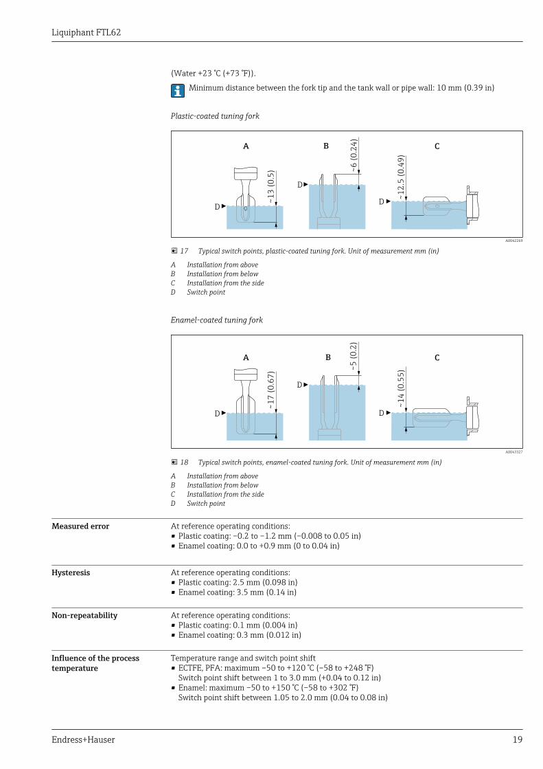
(Water +23 °C (+73 °F)).
Minimum distance between the fork tip and the tank wall or pipe wall: 10 mm (0.39 in)
Plastic-coated tuning fork
~1
3 (
0.5
)
D
A
~1
2.5
(0
.49
)
C
D
~6
(0
.24
)
B
D
A0042269
17 Typical switch points, plastic-coated tuning fork. Unit of measurement mm (in)
A Installation from aboveB Installation from belowC Installation from the sideD Switch point
Enamel-coated tuning fork
~1
7 (
0.6
7)
D
A
~1
4 (
0.5
5)
C
D
D
~5
(0
.2)
B
A0043327
18 Typical switch points, enamel-coated tuning fork. Unit of measurement mm (in)
A Installation from aboveB Installation from belowC Installation from the sideD Switch point
Measured error At reference operating conditions:• Plastic coating: –0.2 to –1.2 mm (–0.008 to 0.05 in)• Enamel coating: 0.0 to +0.9 mm (0 to 0.04 in)
Hysteresis At reference operating conditions:• Plastic coating: 2.5 mm (0.098 in)• Enamel coating: 3.5 mm (0.14 in)
Non-repeatability At reference operating conditions:• Plastic coating: 0.1 mm (0.004 in)• Enamel coating: 0.3 mm (0.012 in)
Influence of the processtemperature
Temperature range and switch point shift• ECTFE, PFA: maximum –50 to +120 °C (–58 to +248 °F)
Switch point shift between 1 to 3.0 mm (+0.04 to 0.12 in)• Enamel: maximum –50 to +150 °C (–58 to +302 °F)
Switch point shift between 1.05 to 2.0 mm (0.04 to 0.08 in)

Liquiphant FTL62
20 Endress+Hauser
Influence of the processpressure
Pressure range and switch point shift• ECTFE, PFA: maximum 0 to 40 bar (0 to 580 psi)
Switch point shift between 0 to –2.0 mm (0 to –0.08 in)• Enamel: maximum 0 to 25 bar (0 to 363 psi)
Switch point shift between 0 to –1.0 mm (0 to –0.04 in)
Influence of the density ofthe process medium (at roomtemperature and normalpressure)
0.5 1 1.5 2
-8
-6
-4
-2
0
2
4
6
[in]
[kg/m!]
C
A ( )ρ
B1 A1
-0.31
-0.24
-0,16
-0,08
0
0.16
0.24
[mm]
0.08B ( )ρ
[ρ]
A0042241
19 Reference switch points via density, plastic coating (ECTFE, PFA)
A Density switch setting (ρ) > 0.7A1 Reference operating condition ρ = 1.0 kg/m3
B Density switch setting (ρ) > 0.5B1 Reference operating condition ρ = 0.7 kg/m3
C Switch point deviation
Density setting• TK type, [mm/10 k]
• ρ > 0.7: –0.25• ρ > 0.5: –0.3
• Pressure type, [mm/10 bar]• ρ > 0.7: –0.3• ρ > 0.5: –0.4

Liquiphant FTL62
Endress+Hauser 21
0.5 1 1.5 2
-8
-6
-4
-2
0
2
4
6
[kg/m!]
C
A ( )ρ
B1 A1
[mm]
B ( )ρ
[ρ]
[in]
-0.31
-0.24
-0,16
-0,08
0
0.16
0.24
0.08
A0042242
20 Reference switch points via density, enamel coating
A Density switch setting (ρ) > 0.7A1 Reference operating condition ρ = 1.0 kg/cm3
B Density switch setting (ρ) > 0.5B1 Reference operating condition ρ = 0.7 kg/cm3
C Switch point deviation
Density setting• TK type, [mm/10 k]
• ρ > 0.7: –0.1• ρ > 0.5: –0.15
• Pressure type, [mm/10 bar]• ρ > 0.7: –0.3• ρ > 0.5: –0.4
InstallationOpen the device only in a dry environment!
Mounting location,orientation
Installation instructions• Any orientation for device with short pipe up to approx. 500 mm (19.7 in)• Vertical orientation for device with long pipe• Minimum distance between the fork tip and the tank wall or pipe wall: 10 mm (0.39 in)

Liquiphant FTL62
22 Endress+Hauser
1
A0042153
21 Examples of installation in a vessel, pipe or tank
1 Temperature spacer/pressure-tight feedthrough (optional) for tank with insulation and/or high processtemperatures
Installation instructions Take viscosity into consideration
Low viscosity
Low viscosity, e. g. water: < 2 000 mPa⋅s
It is permitted to position the tuning fork within the installation socket.
> 25 (0.98)
D
A0042204
22 Installation example for low-viscosity liquids. Unit of measurement mm (in)
D Diameter of installation socket: at least 50 mm (2.0 in)
High viscosity
NOTICEHighly viscous liquids may cause switching delays.‣ Make sure that the liquid can run off the tuning fork easily.‣ Deburr the socket surface.
High viscosity, e. g. viscous oils: < 10 000 mPa⋅s
The tuning fork must be located outside the installation socket!

Liquiphant FTL62
Endress+Hauser 23
> 40 (1.57)
A0042205
23 Installation example for a highly viscous liquid. Unit of measurement mm (in)
Avoid buildup
• Use short installation sockets to ensure that the turning fork can project freely into the vessel• Install preferably flush mount on vessels or in pipes• Leave sufficient distance between the buildup expected on the tank wall and the tuning fork
A0042206
24 Installation examples for a highly viscous process medium
Take clearance into consideration
Allow sufficient space outside the tank for mounting, connection and settings involving theelectronic insert.
A0033236
25 Take clearance into consideration

Liquiphant FTL62
24 Endress+Hauser
Align the tuning fork with the marking
The tuning fork can be aligned with the help of the marking (II symbol) on the rear of the flange.Medium can thus run off easily and buildup is avoided.
A0042207
26 Marking on flange to align the tuning fork
Installing in pipes • Flow velocity up to 5 m/s with viscosity 1 mPa⋅s and density 1 g/cm3 (SGU).Check for correct functioning in the event of other process medium conditions.
• The flow will not be significantly impeded if the tuning fork is correctly aligned and the marking ispointing in the direction of flow.
• The marking is visible when installed.
A0042208
27 Installation in pipes
Aligning the cable entry
2.
1. 3.
4 0.7 Nm
A0042214
28 Housing with external locking screw
Special mountinginstructions
Support the device
NOTICEIf the device is supported incorrectly, shocks and vibrations can damage the coated surface.‣ Only use a support in conjunction with ECTFE or PFA plastic coating.‣ Use suitable supports only.
Support the device in the event of severe dynamic load. Maximum lateral loading capacity of the pipeextensions and sensors: 75 Nm (55 lbf ft).

Liquiphant FTL62
Endress+Hauser 25
A0031874
29 Examples of support in the event of dynamic load
Environment
Ambient temperature range LWARNINGPermitted connection voltage exceeded!‣ For electrical safety reasons, the maximum connection voltage for all electronic inserts at
ambient temperatures below –40 °C (–40 °F) is limited to a maximum of 35 V DC.
–40 to +70 °C (–40 to +158 °F)
Optionally available to order:• –60 °C (–76 °F)
Product Configurator, order code for "Test, Certificate, Declaration" option "JT"• –50 °C (–58 °F)
Product Configurator, order code for "Test, Certificate, Declaration" option "JL"In the hazardous area, the permitted ambient temperature can be limited depending on the zonesand gas groups. Pay attention to the information in the Ex documentation (XA).
The minimum permitted ambient temperature of the plastic housing is limited to –20 °C (–4 °F); forNorth America, "indoor use" applies.
Low-temperature electronic inserts are marked LT.

Liquiphant FTL62
26 Endress+Hauser
Ta
Tp
Tp
Tp
+150
+302
+120
+248
+90
+194
0
32
70158
60140
50122
032
-50
-50
-58
-58
A
DC
B
[°C]
[°C]
[°F]
[°F]
Ta Ta
-60-76
-40-40
A0042264
30 Permitted ambient temperature Ta at the housing as a function of the process temperature Tp in the vessel:
A Device without LED module; at process temperature and FEL64 Tp > 90 °C (194 °F), max. load current 4 AB Device with LED module; at process temperature and FEL64 Tp > 90 °C (194 °F), max. load current 2 AC ECTFE-coatedD PFA- or enamel-coated
• Bluetooth module (non-Ex): –40 to +85 °C (–40 to +185 °F)• Bluetooth module (Ex ia): –40 to +65 °C (–40 to +149 °F), T4• LED module: –40 to +60 °C (–40 to +140 °F)
Outdoor operation in strong sunlight:• Mount the device in the shade• Avoid direct sunlight, particularly in warmer climatic regions• Use a protective cover, which can be ordered as an accessory
Storage temperature –40 to +80 °C (–40 to +176 °F)Optional: –50 °C (–58 °F), –60 °C (–76 °F)
Humidity Operation up to 100 %. Do not open in a condensing atmosphere.
Operating altitude As per IEC 61010-1 Ed.3:• Up to 2 000 m (6 600 ft) above sea level• Can be extended to 3 000 m (9 800 ft) above sea level if overvoltage protection is used
Climate class As per IEC 60068-2-38 test Z/AD
Degree of protection In accordance with DIN EN 60529, NEMA 250
IP66/IP68 NEMA 4x/6PTypes of housing:• Single compartment; plastic• Single compartment; aluminum, coated; Ex d/XP• Single compartment; 316L, cast; Ex d/XP• Dual compartment L-shaped, aluminum, coated; Ex d/XP
Ordering information: Select the required option in the "Electrical connection" order code.Exclusion criteria are taken into account automatically.
If the "M12 plug" option is selected as electrical connection, then IP66/67 NEMA TYPE 4x isvalid for all housing types.
Vibration resistance As per IEC60068-2-64-2009a(RMS) = 50 m/s2, f = 5 to 2 000 Hz, t = 3 planes x 2 h

Liquiphant FTL62
Endress+Hauser 27
Shock resistance In accordance with IEC60068-2-27-2008: 300 m/s² [= 30 gn] + 18 ms
gn: standard acceleration of gravity
Mechanical load Support the device in the event of severe dynamic load. Maximum lateral loading capacity of the pipeextensions and sensors: 75 Nm (55 lbf ft).
Additional details in the "Support the device" section.
Electromagneticcompatibility
• Electromagnetic compatibility as per EN 61326 series and NAMUR recommendation EMC (NE21)• The requirements of EN 61326-3-1 for the safety function (SIL) are fulfilled
Details are available in the supplementary Functional Safety Manual.
Process
Process temperature range • ECTFE: –50 to +120 °C (–58 to +248 °F)• PFA: –50 to +150 °C (–58 to +302 °F)• Enamel:–50 to +150 °C (–58 to +302 °F)Pay attention to the pressure and temperature dependency. Additional details in the "Processpressure range" section.
Thermal shock ≤ 120 K/s
Process pressure range LWARNINGThe maximum pressure for the measuring device is dependent on the lowest-rated element,with regard to pressure, of the selected components. This means that it is necessary to payattention to the process connection as well as the sensor.‣ For pressure specifications, see the "Mechanical construction" section.‣ The measuring device must be operated only within the specified limits!‣ The Pressure Equipment Directive (2014/68/EU) uses the abbreviation "PS". The abbreviation "PS"
corresponds to the MWP (maximum working pressure) of the measuring device.
The following data apply over the entire temperature range. Pay attention to exceptions for flangeprocess connections!
• ECTFE, PFA: –1 to 40 bar (–14.5 to 580 psi)• Enamel: max. –1 to 25 bar (–14.5 to 363 psi)Refer to the following standards for the permitted pressure values of the flanges at highertemperatures:• pR EN 1092-1: 2005 With regard to its stability-temperature property, the material 1.4435 is
identical to 1.4404, which is classed as 13E0 in EN 1092-1 Tab. 18. The chemical composition ofthe two materials can be identical.
• ASME B 16.5• JIS B 2220In each case, the lowest value from the derating curves of the device and the selected flange applies.
Canadian CRN approval: more details on the maximum pressure values are available in the downloadarea of the product page under "www.endress.com".
Test pressure Test pressure = 1.5 · PN• ECTFE, PFA: PN = 40 bar (580 psi)
Enamel: PN = 25 bar (362.5 psi)• Membrane burst pressure at 200 bar (2 900 psi)The device function is limited during the pressure test.
The mechanical integrity is guaranteed at pressures up to 1.5 times the process nominal pressurePN.
State of aggregation Liquid

Liquiphant FTL62
28 Endress+Hauser
Density Liquids with density > 0.7 g/cm3
Switch position > 0.7 g/cm3 (order configuration)
Liquids with density 0.5 to 0.8 g/cm3
Switch position > 0.5 g/cm3 (can be configured via DIP switch)
Optionally available to order: Liquids with density > 0.4 g/cm3 (not for devices with SILapproval)Fixed value that cannot be edited. The function of the DIP switch is interrupted.Order code for "Service", option "Default density setting > 0.4 g/cm3"
Viscosity ≤ 10 000 mPa⋅s
Pressure shocks ≤20 bar/s (290 psi/s)
Pressure tightness Up to vacuum
In vacuum evaporation systems, the density of the liquids can drop to a very low value: selectdensity setting 0.4.
Solids contents ø ≤ 5 mm (0.2 in)
Lateral loading capacity ≤75 Nm

Liquiphant FTL62
Endress+Hauser 29
Mechanical constructionFor the dimensions, see the Product Configurator: www.endress.com
Search for product → click "Configuration" to the right of the product image → afterconfiguration click "CAD"
The following dimensions are rounded values. For this reason, they may deviate slightly fromthe dimensions given on www.endress.com.
Design, dimensions Device height
The device height is made up of the following components:• Housing including cover• Temperature spacer and/or pressure-tight feedthrough (second line of defense), optional• Pipe extension or short pipe, optional• Process connectionThe individual heights of the components can be found in the following sections:• Calculate device height and add the individual heights of the components• Take the installation clearance into consideration (space that is required to install the device)
AB
C
D
E
F
A0042256
31 Components for calculating the device height
A Housing including coverB Temperature spacer, pressure-tight feedthrough (optional), details in the Product ConfiguratorC Process connection flangeD Pipe extensionE Short pipeF Installation clearance
Process connection, sealing surface, pipe extension and tuning fork are plastic-coated orenamel-coated.

Liquiphant FTL62
30 Endress+Hauser
Housing and cover
All housings can be aligned. The locking screw on metal housings can be used to secure thealignment of the housing.
Devices with a Bluetooth or LED module require a high cover (transparent plastic cover or aluminumcover with sight glass). The Bluetooth or LED module cannot be used in conjunction with the 316Lsingle compartment housing, cast.
Dimensions of housing and cover
!94 (3.7)
12
3 (
4.8
4)
10
1 (
3.9
8)
A0035911
32 Single compartment; plastic; Product Configurator: order code for "Housing; material", option A. Unit ofmeasurement mm (in)
!101 (3.98)
11
8 (
4.6
5)
14
0 (
5.5
1)
A0039401
33 Single compartment; aluminum, coated; with Ex d/XP approval; Product Configurator: order code for"Housing; material", option B. Unit of measurement mm (in)
!101 (3.98)
10
3 (
4.0
6)
12
6 (
4.9
6)
13
6 (
5.3
5)
1
A0039402
34 Single compartment; aluminum, coated; Product Configurator: order code for "Housing; material", option B.Unit of measurement mm (in)
1 Cover for Ex ec approval

Liquiphant FTL62
Endress+Hauser 31
!101 (3.98)
11
8 (
4.6
5)
A0035590
35 Single compartment 316L, cast; with Ex d/XP approval also; Product Configurator: order code for"Housing; material", option C. Unit of measurement mm (in)
13
1 (
5.1
6)
16
3 (
6.4
2)
!147 (5.79)
!1
01
(3
.98
)
A0035591
36 Dual compartment, L-shaped; aluminum, coated; with Ex d/XP approval also; Product Configurator: ordercode for "Housing; material", option M. Unit of measurement mm (in)
Ground terminal
• Ground terminal inside the housing, max. conductor cross-section 2.5 mm2 (14 AWG)• Ground terminal outside the housing, max. conductor cross-section 4 mm2 (12 AWG)• If safety extra-low voltage is used to supply power to electronic inserts, do not connect protective
ground
Cable glands
Cable diameter:• Plastic: ø5 to 10 mm (0.2 to 0.38 in)• Nickel-plated brass: ø7 to 10.5 mm (0.28 to 0.41 in)• Stainless steel: ø7 to 12 mm (0.28 to 0.47 in)The scope of delivery comprises:• 1 cable gland installed• 1 cable gland sealed with dummy plug
A second cable gland (not installed) is also included in the scope of delivery of the relayelectronics.
Exceptions: With Ex d/XP, only threaded entries are permitted.
Temperature spacer (optional)
Provides sealed insulation for the vessel and a normal ambient temperature for the housing

Liquiphant FTL62
32 Endress+Hauser
140 (5.51)
1
A0042231
37 Temperature spacer, pressure-tight feedthrough (1). Unit of measurement mm (in)
Product Configurator, order code for "Sensor design":• Option "MR" for temperature spacer• Option "MS" for pressure-tight feedthrough (second line of defense)
In the event of damage to the sensor, protects the housing from exposure to vessel pressures up to100 bar (1 450 psi).
The "Pressure-tight feedthrough" option can only be selected in conjunction with the"Temperature spacer" option.
Probe design
Short pipeFixed length (A)• Base material: 316L• Sensor length: 115 mm (4.53 in)• Flanges according to DIN/EN, ASME, JIS from DN 40 / 1½"
Radius (R) ≤ 4 mm (0.16 in) for DN25/ASME flangesPipe extensionVariable length L (B)• Base material: 316L• Sensor length depends on enamel coating: 148 to 1 200 mm (5.83 to 47.2 in)• Sensor length depends on plastic coating: 148 to 3 000 mm (5.83 to 118 in)
L≥1
15
(4
.53
)≥
!
! R<4
(R<0.1
6)R<4
(R<0.1
6)
BA
A0042250
38 Probe design: short pipe, pipe extension. Unit of measurement mm (in)
A Short pipe: fixed lengthB Pipe extension: length L variable Maximum diameter: depends on coating materialR Radius: take into consideration for counterflange
Coating material and layer thickness
The maximum diameter depends on the coating material.
ECTFE• Lower limit: 0.5 mm (0.02 in)• Upper limit: 1.6 mm (0.06 in)• Maximum diameter: 24.6 mm (0.97 in)

Liquiphant FTL62
Endress+Hauser 33
PFA (EdlonTM), PFA (Ruby Red), PFA (conductive)• Lower limit: 0.45 mm (0.02 in)• Upper limit: 1.6 mm (0.06 in)• Maximum diameter: 24.6 mm (0.97 in)
PFA (EdlonTM): FDA-compliant material in accordance with 21 CFR Part 177.1550/2600
Enamel• Lower limit: 0.4 mm (0.02 in)• Upper limit: 0.8 mm (0.03 in)• Maximum diameter: 23 mm (0.91 in)
Properties and benefits of coatings
ECTFE (ethylene chlorotrifluoroethylene)• Thermoplastic fluoropolymer coating• Also known as HALAR®• Very good chemical and corrosion resistance• High abrasion performance• Good non-stick properties• Ideal for use in the chemicals industryPFA (perfluoroalkoxy)• Properties similar to PTFE (polytetrafluoroethylene) and FEP (perfluoroethylenepropylene)• Also known as TEFLON®• Very good chemical and corrosion resistance• High abrasion performance• Good non-stick and sliding properties• High temperature resistance• Ideal for use in the chemical and pharmaceutical industry• Available as PFA (Edlon TM), PFA (Ruby Red®) or PFA (conductive), developed specifically for use
in hazardous areasPFA (EdlonTM): FDA-compliant material in accordance with 21 CFR Part 177.1550/2600
Enamel• Glass-like material• Very good chemical and corrosion resistance• Acid-resistant• High temperature resistance• Dirt-repellent• Low resistance to impact
Use of the selected coating material influences the approved IIB/IIC gas groups. Pay attention tothe information in the safety documentation (XA).
Tuning fork
40 (1.57)
17
.2 (
0.6
8)
17
(0
.67
)
1.5
(0
.06
)
10
(0
.39
)
A0038269
39 Tuning fork with plastic coating. Unit of measurement mm (in)

Liquiphant FTL62
34 Endress+Hauser
46.5 (1.83)
17
(0
.67
)
17
.2 (
0.6
8)
1.5
(0
.06
)
10
(0
.39
)
A0041851
40 Tuning fork with enamel coating. Unit of measurement mm (in)
Process connections
ASME B16.5 flanges, RF
Pressure rating Type Material Weight
Cl.150 NPS 1" 316/316L 1.0 kg (2.21 lb)
Cl.150 NPS 1-½" 316/316L 1.5 kg (3.31 lb)
Cl.150 NPS 2" 316/316L 2.4 kg (5.29 lb)
Cl.150 NPS 2" Enamel 1.0487 2.4 kg (5.29 lb)
Cl.150 NPS 3" 316/316L 4.9 kg (10.8 lb)
Cl.150 NPS 4" 316/316L 7 kg (15.44 lb)
Cl.300 NPS 2" 316/316L 3.2 kg (7.06 lb)
Cl.300 NPS 2" Enamel 1.0487 3.2 kg (7.06 lb)
EN flanges EN 1092-1, A
Pressure rating Type Material Weight
PN6 DN50 316L (1.4404) 1.6 kg (3.53 lb)
PN10/16 DN100 316L (1.4404) 5.6 kg (12.35 lb)
PN25/40 DN25 316L (1.4404) 1.3 kg (2.87 lb)
PN25/40 DN32 316L (1.4404) 2.0 kg (4.41 lb)
PN25/40 DN40 316L (1.4404) 2.4 kg (5.29 lb)
PN25/40 DN50 316L (1.4404) 3.2 kg (7.06 lb)
PN25/40 DN80 316L (1.4404) 5.9 kg (13.01 lb)
EN flanges EN 1092-1, B1
Pressure rating Type Material Weight
PN25/40 DN50 Enamel 1.0487 3.2 kg (7.06 lb)
PN25/40 DN80 Enamel 1.0487 5.9 kg (13.01 lb)
JIS flanges B2220 (RF)
Pressure rating Type Material Weight
10K 10K 50A 316L (1.4404) 1.7 kg (3.75 lb)

Liquiphant FTL62
Endress+Hauser 35
Process connection, sealing surface
• Flange ASME B16.5, RF (Raised Face)• Flange EN1092-1, Form A• Flange EN1092-1, Form B1• Flange JIS B2220, RF (Raised Face)
Weight Basic weight: 0.65 kg (1.43 lb)The basic weight comprises:• Sensor (short pipe)• Electronic insert• Housing: single compartment, plastic with cover
Differences in weight result from the housing, LED or Bluetooth module (incl. high cover).
In addition to the basic weight:
Bluetooth module0.1 kg (0.22 lb)LED module0.1 kg (0.22 lb)Housing• Single compartment, aluminum, coated: 0.8 kg (1.76 lb)
optional LED module or Bluetooth module with high cover: 0.38 kg (0.84 lb)• 316L cast: 1.21 kg (2.67 lb)• Dual compartment, L-shaped; aluminum, coated: 1.22 kg (2.69 lb)
optional LED module or Bluetooth module with high cover: 0.38 kg (0.84 lb)Temperature spacer0.6 kg (1.32 lb)Pressure-tight feedthrough0.7 kg (1.54 lb)Pipe extension• 1 000 mm: 0.9 kg (1.98 lb)• 100 in: 2.3 kg (5.07 lb)Process connectionsSee "Process connections" sectionPlastic protective cover0.2 kg (0.44 lb)
Materials Materials in contact with process
Extension pipe• With plastic coating: carrier material: 316L (1.4435 or 1.4404)• With enamel coating: carrier material: Alloy C4Tuning fork• With plastic coating: carrier material: 316L (1.4435 or 1.4404)• With enamel coating: carrier material: Alloy C4Flange• With plastic coating ECTFE, PFA (EdlonTM) 1), PFA (Ruby Red), PFA (conductive): carrier material:
316L (1.4404)• With enamel coating: carrier material: A516 Gr.60 (1.0487)
Materials not in contact with process
Plastic housing• Housing: PBT/PC• Blind cover: PBT/PC• Transparent cover: PBT/PC or PA12• Cover seal: EPDM• Potential equalization: 316L• Seal under potential equalization: EPDM
1) FDA-compliant material in accordance with 21 CFR Part 177.1550/2600

Liquiphant FTL62
36 Endress+Hauser
• Dummy plug: PBT-GF30-FR• M20 cable gland: PA• Seal on dummy plug and cable gland: EPDM• Adapter as replacement for cable glands: 316L• Adapter for NPT¾: plastic• Nameplate: plastic foil• TAG plate: plastic foil, metal or provided by the customerAluminum housing, coated• Housing: EN AC 44300 aluminum• Blind cover: EN AC 44300 aluminum• Cover with sight glass: EN AC 44300 aluminum, PC Lexan 943A synthetic glass
Cover with sight glass made of polycarbonate, optionally available to order. For Ex d applications,the sight glass is made from borosilicate.
• Cover sealing materials: HNBR• Cover sealing materials: FVMQ (in low-temperature version only)• Nameplate: plastic foil• TAG plate: plastic foil, stainless steel or provided by the customer• Cable glands M20: select material (stainless steel, nickel-plated brass, polyamide)Stainless steel housing• Housing: stainless steel AISI 316L (1.4409)• Cover: AISI 316L (1.4409)• Cover sealing materials: FVMQ (in low temperature version only)• Cover sealing materials: HNBR• Nameplate: stainless steel 316L• TAG plate: plastic foil, stainless steel or provided by the customer• Cable glands M20: select material (stainless steel, nickel-plated brass, polyamide)Process connections• Flanges, plastic-coated: 316L (1.4404)• Flanges, enamel-coated: 1.0487 (ASTMA 529)• Additional flanges:
• According to EN/DIN 1092-1 from DN 25• According to ASME B16.5 from 1",• According to JIS B 2220 (RF) from 10K50
Operability
Operating concept • Operation with button and DIP switches on the electronic insert• Display with optional Bluetooth module and SmartBlue (app) via Bluetooth® wireless technology• Indication of operational status (switch status or alarm status) with optional LED module (lights
visible from the outside)• For plastic housing and aluminum housing (standard and Ex d) in conjunction with the DC-PNP
(electronic insert FEL62) and relay electronics (electronic inserts FEL64, FEL64DC)• Ordering information: Product Configurator, order code for "Display; operation" option "B"
Liquiphant FTL62
Endress+Hauser 37
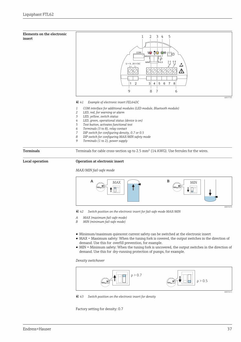
Elements on the electronicinsert
MIN
>0,7MAX
>0,5
COM
U = 9...20 V DC
4
3 5 8
7
6
L-L+
1 2 3 4 5 6 7 8
1 2 3 4 5
6789
A0037705
41 Example of electronic insert FEL64DC
1 COM interface for additional modules (LED module, Bluetooth module)2 LED, red, for warning or alarm3 LED, yellow, switch status4 LED, green, operational status (device is on)5 Test button, activates functional test6 Terminals (3 to 8), relay contact7 DIP switch for configuring density, 0.7 or 0.58 DIP switch for configuring MAX/MIN safety mode9 Terminals (1 to 2), power supply
Terminals Terminals for cable cross-section up to 2.5 mm2 (14 AWG). Use ferrules for the wires.
Local operation Operation at electronic insert
MAX/MIN fail-safe mode
A BMAX MIN
A0033470
42 Switch position on the electronic insert for fail-safe mode MAX/MIN
A MAX (maximum fail-safe mode)B MIN (minimum fail-safe mode)
• Minimum/maximum quiescent current safety can be switched at the electronic insert• MAX = Maximum safety: When the tuning fork is covered, the output switches in the direction of
demand. Use this for overfill prevention, for example.• MIN = Minimum safety: When the tuning fork is uncovered, the output switches in the direction of
demand. Use this for dry-running protection of pumps, for example.
Density switchover
ρ > 0.7
ρ > 0.5
A0033471
43 Switch position on the electronic insert for density
Factory setting for density: 0.7
Liquiphant FTL62
38 Endress+Hauser
Liquids with density > 0.7 g/cm3
Switch position > 0.7 g/cm3 (order configuration)
Liquids with density: 0.5 to 0.8 g/cm3
Switch position > 0.5 g/cm3 (can be configured via DIP switch)
Optionally available to order: Liquids with density > 0.4 g/cm3 (not for devices with SILapproval)Fixed value that cannot be edited. The function of the DIP switch is interrupted.Order code for "Service", option "Default density setting > 0.4 g/cm3".
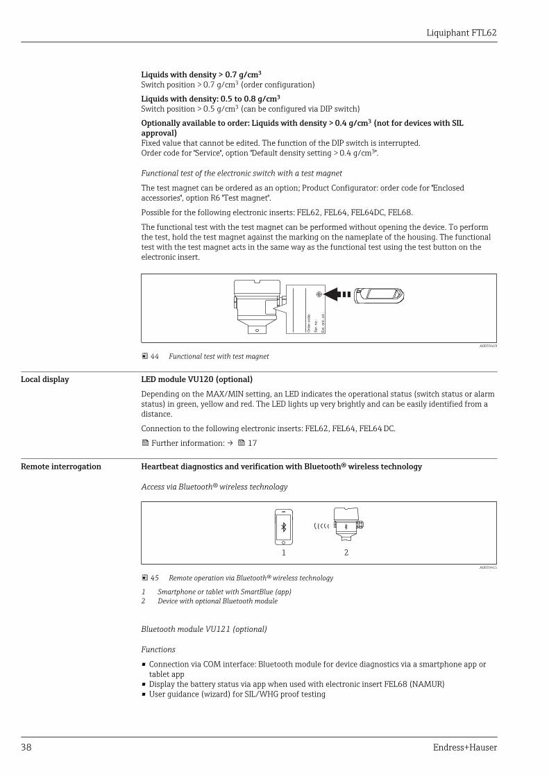
Functional test of the electronic switch with a test magnet
The test magnet can be ordered as an option; Product Configurator: order code for "Enclosedaccessories", option R6 "Test magnet".
Possible for the following electronic inserts: FEL62, FEL64, FEL64DC, FEL68.
The functional test with the test magnet can be performed without opening the device. To performthe test, hold the test magnet against the marking on the nameplate of the housing. The functionaltest with the test magnet acts in the same way as the functional test using the test button on theelectronic insert.
Se
r. n
o.:
Ord
er
co
de
:
Ext.
ord
. cd
.:
A0033419
44 Functional test with test magnet
Local display LED module VU120 (optional)
Depending on the MAX/MIN setting, an LED indicates the operational status (switch status or alarmstatus) in green, yellow and red. The LED lights up very brightly and can be easily identified from adistance.
Connection to the following electronic inserts: FEL62, FEL64, FEL64 DC.
Further information: → 17
Remote interrogation Heartbeat diagnostics and verification with Bluetooth® wireless technology
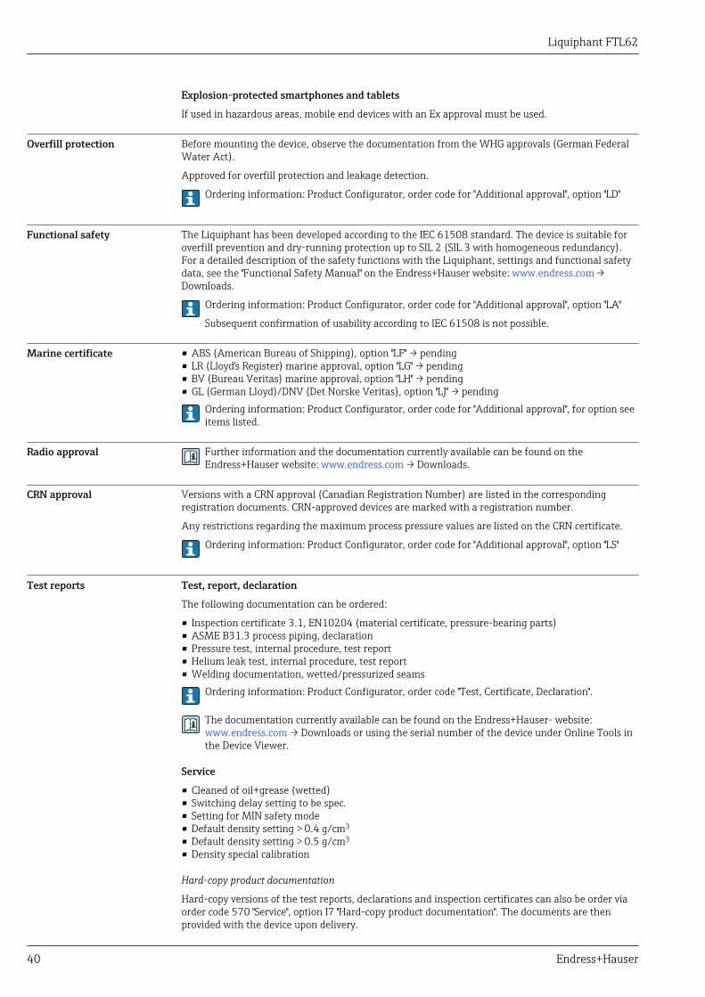
Access via Bluetooth® wireless technology
1 2
A0033411
45 Remote operation via Bluetooth® wireless technology
1 Smartphone or tablet with SmartBlue (app)2 Device with optional Bluetooth module
Bluetooth module VU121 (optional)
Functions
• Connection via COM interface: Bluetooth module for device diagnostics via a smartphone app ortablet app
• Display the battery status via app when used with electronic insert FEL68 (NAMUR)• User guidance (wizard) for SIL/WHG proof testing

Liquiphant FTL62
Endress+Hauser 39
• Visible in the livelist 10 seconds after the Bluetooth search commences• Data can be read from the Bluetooth module 60 seconds after the supply voltage is switched on• Display of the current vibration frequency and the switching state of the deviceThe yellow LED flashes when the Bluetooth module is connected to another Bluetooth device, e. g.mobile phone.
Heartbeat Technology
Additional details in the "Application packages" section.
Diagnostic information Heartbeat Technology
The electronics module and the tuning fork are checked using Heartbeat Technology, and averification of the Liquiphant is performed. The switch output is not changed during this test. Thetest can be performed at any time and does not influence the switch output in the safety circuit. Inthe case of proof-testing, the SmartBlue app supports users in every step of the test. The switchoutput is also switched during this test. During the proof-test, alternative monitoring measures mustbe taken to ensure process safety.
Proof test
During the proof test, the SmartBlue app provides support for each individual stage of the test(proof-test wizard). The switch output is also switched during this test. During the proof test,alternative monitoring measures must be taken to ensure process safety.
Evaluation of the vibration frequency
If the vibration frequency exceeds the upper warning frequency, a warning is displayed. A warning isactivated when the fork becomes corroded, for example. The switch output remains in the currentstate. The warning is displayed in the SmartBlue app and output in the Heartbeat Technologyprotocol. When a warning occurs, it is necessary to check the Liquiphant sensor.
The current oscillation frequency must be in the range between the upper and lower alarmfrequency. If the current oscillation frequency is above the upper alarm frequency or below the loweralarm frequency, an alarm is output. The output switches to the safety-oriented state.
Certificates and approvalsThe certificates, approvals and other documentation currently available can be accessed asfollows:Endress+Hauser website: www.endress.com → Downloads.
CE mark The measuring system complies with the statutory requirements of the applicable EC Directives.These are listed in the corresponding EC Declaration of Conformity along with the standards applied.Endress+Hauser confirms successful testing of the device by affixing to it the CE mark.
RCM-Tick marking The supplied product or measuring system meets the ACMA (Australian Communications and MediaAuthority) requirements for network integrity, interoperability, performance characteristics as wellas health and safety regulations. Here, especially the regulatory arrangements for electromagneticcompatibility are met. The products are labelled with the RCM- Tick marking on the name plate.
A0029561
Ex approval All data relating to explosion protection are provided in separate Ex documentation and are availablefrom the Downloads Area. The Ex documentation is supplied as standard with all Ex devices.
Ex temperature class: T1 to T6
If using type of protection Ex i and electronic insert FEL68 (NAMUR) and the Bluetooth modulein addition (battery required): T4 to T1.
Liquiphant FTL62
40 Endress+Hauser
Explosion-protected smartphones and tablets
If used in hazardous areas, mobile end devices with an Ex approval must be used.
Overfill protection Before mounting the device, observe the documentation from the WHG approvals (German FederalWater Act).
Approved for overfill protection and leakage detection.
Ordering information: Product Configurator, order code for "Additional approval", option "LD"
Functional safety The Liquiphant has been developed according to the IEC 61508 standard. The device is suitable foroverfill prevention and dry-running protection up to SIL 2 (SIL 3 with homogeneous redundancy).For a detailed description of the safety functions with the Liquiphant, settings and functional safetydata, see the "Functional Safety Manual" on the Endress+Hauser website: www.endress.com → Downloads.
Ordering information: Product Configurator, order code for "Additional approval", option "LA"
Subsequent confirmation of usability according to IEC 61508 is not possible.
Marine certificate • ABS (American Bureau of Shipping), option "LF" → pending• LR (Lloyd's Register) marine approval, option "LG" → pending• BV (Bureau Veritas) marine approval, option "LH" → pending• GL (German Lloyd)/DNV (Det Norske Veritas), option "LJ" → pending
Ordering information: Product Configurator, order code for "Additional approval", for option seeitems listed.
Radio approval Further information and the documentation currently available can be found on theEndress+Hauser website: www.endress.com → Downloads.
CRN approval Versions with a CRN approval (Canadian Registration Number) are listed in the correspondingregistration documents. CRN-approved devices are marked with a registration number.
Any restrictions regarding the maximum process pressure values are listed on the CRN certificate.
Ordering information: Product Configurator, order code for "Additional approval", option "LS"
Test reports Test, report, declaration
The following documentation can be ordered:
• Inspection certificate 3.1, EN10204 (material certificate, pressure-bearing parts)• ASME B31.3 process piping, declaration• Pressure test, internal procedure, test report• Helium leak test, internal procedure, test report• Welding documentation, wetted/pressurized seams
Ordering information: Product Configurator, order code "Test, Certificate, Declaration".
The documentation currently available can be found on the Endress+Hauser- website:www.endress.com → Downloads or using the serial number of the device under Online Tools inthe Device Viewer.
Service
• Cleaned of oil+grease (wetted)• Switching delay setting to be spec.• Setting for MIN safety mode• Default density setting > 0.4 g/cm3
• Default density setting > 0.5 g/cm3
• Density special calibration
Hard-copy product documentation
Hard-copy versions of the test reports, declarations and inspection certificates can also be order viaorder code 570 "Service", option I7 "Hard-copy product documentation". The documents are thenprovided with the device upon delivery.

Liquiphant FTL62
Endress+Hauser 41
Pressure EquipmentDirective
Pressure equipment with allowable pressure ≤ 200 bar (2 900 psi)
Pressure instruments with a flange and threaded boss that do not have a pressurized housing do notfall within the scope of the Pressure Equipment Directive, irrespective of the maximum allowablepressure.
Reasons:
According to Article 2, point 5 of EU Directive 2014/68/EU, pressure accessories are defined as"devices with an operational function and having pressure-bearing housings".
If a pressure instrument does not have a pressure-bearing housing (no identifiable pressure chamberof its own), there is no pressure accessory present within the meaning of the Directive.
Process seal as per ANSI/ISA12.27.01
North American practice for the installation of process seals. In accordance with ANSI/ISA 12.27.01,Endress+Hauser devices are designed as either single seal or dual seal devices with a warningmessage. This allows the user to waive the use of - and save the cost of installing - an externalsecondary process seal in the protective conduit as required in ANSI/NFPA 70 (NEC) and CSA 22.1(CEC). These instruments comply with the North-American installation practice and provide a verysafe and cost-saving installation for pressurized applications with hazardous fluids. Moreinformation is provided in the Safety Instructions (XA) for the relevant device.
Aluminum, stainless steel and plastic housing are approved as single-seal devices.
China RoHS symbol China RoHS 1, law SJ/T 11363-2006: The measuring system complies with the substancerestrictions of the Restriction on Hazardous Substances Directive (RoHS).
RoHS The measuring system complies with the substance restrictions of the Restriction on HazardousSubstances Directive 2011/65/EU (RoHS 2).
Additional certification EAC conformity
The measuring system meets the legal requirements of the applicable EAC guidelines. These arelisted in the corresponding EAC Declaration of Conformity together with the standards applied.
Endress+Hauser confirms successful testing of the device by affixing to it the EAC mark.
ASME B 31.3 Design and materials in accordance with ASME B31.3. The welds are through-penetration weldedand meet the requirements of the ASME Boiler and Pressure Vessel Code, Section IX and EN ISO15614-1.
Ordering informationDetailed ordering information is available from the following sources:• In the Product Configurator on the Endress+Hauser website: www.endress.com → Click "Corporate"
-> Select country → Click "Products"→ Select product using the filters and search field → Openproduct page → The "Configuration" button to the right of the product image opens the ProductConfigurator.
• Endress+Hauser Sales Center: www.addresses.endress.comProduct Configurator - the tool for individual product configuration• Up-to-the-minute configuration data• Depending on the device: Direct input of measuring point-specific information such as
measuring range or operating language• Automatic verification of exclusion criteria• Automatic creation of the order code and its breakdown in PDF or Excel output format• Ability to order directly in the Endress+Hauser Online Shop
TAG Measuring point (TAG)
The device can be ordered with a tag name.

Liquiphant FTL62
42 Endress+Hauser
Position of the tag markingChoose from the following in the additional specification:• Tag plate, stainless steel• Plastic film• Supplied label/plate• RFID TAG• RFID TAG + tag plate stainless steel• RFID TAG + plastic film• RFID TAG + supplied label/plateDefinition of the tag nameSpecify in the additional specification:3 lines containing up to 18 characters eachThe specified tag name appears on the selected label and/or on the RFID TAG.Presentation in the SmartBlue appThe first 32 characters of the tag nameThe tag name can always be changed specifically for the measuring point via Bluetooth.
Application packagesOrdering information in the Product Configurator:• Order code for "Application package", option EH "Heartbeat Verification + Monitoring" can
only be selected in conjunction with optional Bluetooth module:Order code for "Accessory mounted", option "NF"
• In conjunction with electronic insert FEL68 (2-wire NAMUR):Order code for "Application package", option EL "Prepared for Heartbeat Verification +Monitoring"The Bluetooth module, including the required battery, must be ordered separately in thiscase:Order code for "Accessories", option NG "Prepared for Bluetooth".
Order options that must be selected together, or that are mutually exclusive, are automaticallydisplayed in the Product Configurator.
Heartbeat Technologymodule
Heartbeat DiagnosticsContinuously monitors and evaluates the device status and process conditions. Generates diagnosticmessages when certain events occur and provides troubleshooting measures in accordance withNAMUR NE 107.Heartbeat VerificationPerforms a verification of the current device status upon request and generates a HeartbeatTechnology verification report showing the result of the verification.Heartbeat MonitoringContinuously provides device and/or process data for an external system. Analysis of this data formsthe basis for process optimization and predictive maintenance.
Heartbeat Verification The "Heartbeat Verification" module includes the Heartbeat Verification Wizard, which performs averification of the current device condition and generates the Heartbeat Technology verificationreport:• The wizard can be used via the SmartBlue app.• The wizard guides the user through the entire process of generating the verification report.• The operating hours counter and minimum/maximum temperature indicator (peakhold) are
displayed.• In the event of an increase in the oscillation frequency of the fork, a corrosion warning will appear.• The order configuration of the oscillation frequency in air is indicated in the verification report. An
increased oscillation frequency indicates the presence of corrosion. A reduced oscillation frequencyindicates that there is buildup present or that the sensor is covered by the medium. Deviations inthe oscillation frequency compared to the oscillation frequency on delivery may occur due to theprocess temperature and process pressure.

Liquiphant FTL62
Endress+Hauser 43
Proof testing for SIL/WHGdevices 2)
The "SIL Prooftest", "WHG Prooftest" or "SIL/WHG Prooftest" module includes a wizard for the prooftesting that is required at appropriate intervals for the following applications: SIL (IEC61508/IEC61511), WHG (German Federal Water Act):• The wizard can be used via the SmartBlue app.• The wizard guides the user through the entire process of generating the verification report.• The verification report can be saved as a PDF file.
Accessories
Test magnet Order number: 71437508
A0039209
46 Test magnet
Weather protection cover fordual-compartment housing,aluminum
• Material: stainless steel 316L• Order number: 71438303
81 (3.19)
103 (4.06)
10
2.5
(4
.04
)
73
.5 (
2.8
9)
13
5 (
5.3
1)
229.4 (9.03)
136.7 (5.38)
Ø65 (2.56)
A0039231
47 Weather protection cover for dual-compartment housing, aluminum. Unit of measurement mm (in)
Protective cover for singlecompartment housing,aluminum or 316L
• Material: plastic• Order number: 71438291
140 (5.51) 32 (1.26)
115 (4.53)
12
2 (
4.8
)
A0038280
48 Protective cover for single compartment housing, aluminum or 316L. Unit of measurement mm (in)
2) Available only for devices with SIL or WHG approval
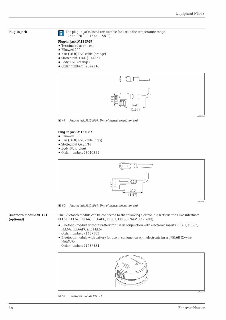
Liquiphant FTL62
44 Endress+Hauser
Plug-in jack The plug-in jacks listed are suitable for use in the temperature range–25 to +70 °C (–13 to +158 °F).
Plug-in jack M12 IP69• Terminated at one end• Elbowed 90 °• 5 m (16 ft) PVC cable (orange)• Slotted nut 316L (1.4435)• Body: PVC (orange)• Order number: 52024216
27
.5(1
.08
)
40³
(1.57)
A0023713
49 Plug-in jack M12 IP69. Unit of measurement mm (in)
Plug-in jack M12 IP67• Elbowed 90 °• 5 m (16 ft) PVC cable (gray)• Slotted nut Cu Sn/Ni• Body: PUR (blue)• Order number: 52010285
27
.5
(1.0
8)
40³
(1.57)
A0022292
50 Plug-in jack M12 IP67. Unit of measurement mm (in)
Bluetooth module VU121(optional)
The Bluetooth module can be connected to the following electronic inserts via the COM interface:FEL61, FEL62, FEL64, FEL64DC, FEL67, FEL68 (NAMUR 2-wire).
• Bluetooth module without battery for use in conjunction with electronic inserts FEL61, FEL62,FEL64, FEL64DC and FEL67Order number: 71437383
• Bluetooth module with battery for use in conjunction with electronic insert FEL68 (2-wireNAMUR)Order number: 71437381
Contains
FCC ID:IC:
A0039257
51 Bluetooth module VU121

Liquiphant FTL62
Endress+Hauser 45
More detailed information is available:• Product Configurator on the Endress+Hauser web page: www.endress.com• Endress+Hauser Sales Center www.addresses.endress.com
A tall cover is required (transparent plastic cover or aluminum cover with sight glass) whenusing or retrofitting the Bluetooth module. The Bluetooth module cannot be used inconjunction with the single compartment 316L housing, cast. The cover depends on thehousing and approval of the device.
LED module VU120(optional)
A brightly lit LED indicates the operational status (switch status or alarm status). The LED modulecan be connected to the following electronic inserts: FEL62, FEL64, FEL64DC.
Order number: 71437382
RDGN YE
A0043925
52 LED module, the LED lights up in green (GN), yellow (YE) or red (RD)
More detailed information is available:• Product Configurator on the Endress+Hauser web page: www.endress.com• Endress+Hauser Sales Center www.addresses.endress.com
A tall cover is required (transparent plastic cover or aluminum cover with sight glass) whenusing or retrofitting the Bluetooth module. Use of the Bluetooth module is not possible inconjunction with the single compartment 316L housing, cast. The cover depends on thehousing and approval of the device.
Supplementary documentationThe certificates, approvals and other documentation currently available can be accessed asfollows:Endress+Hauser website: www.endress.com → Downloads.
Special Documentation SD02389F: Radio approval for Bluetooth module VU121
Supplementary device-dependent documentation
Document type: Operating Instructions (BA)Installation and initial commissioning ‒ contains all functions in the operating menu that arerequired for a typical measuring task. Functions beyond this scope are not included.BA02036FDocument type: Brief Operating Instructions (KA)Quick guide to the first measured value ‒ includes all essential information from the incomingacceptance to the electrical connection.KA01479FDocument type: Safety Instructions, certificatesDepending on the approval, Safety Instructions are also supplied with the device, e. g. XA. Thisdocumentation is an integral part of the Operating Instructions.The nameplate indicates the Safety Instructions (XA) that are relevant to the device.

Liquiphant FTL62
46 Endress+Hauser
Registered trademarks
The Bluetooth® word mark and logos are registered trademarks owned by the Bluetooth SIG, Inc. andany use of such marks by Endress+Hauser is under license. Other trademarks and trade names arethose of their respective owners.Apple®Apple, the Apple logo, iPhone, and iPod touch are trademarks of Apple Inc., registered in the U.S.and other countries. App Store is a service mark of Apple Inc.Android®Android, Google Play and the Google Play logo are trademarks of Google Inc.


www.addresses.endress.com
*71498561*71498561