lisa pathfinder / smart-2
TRANSCRIPT
LISA Pathfinder / SMART-2
LISA Pathfinder and the LTP experiment
38th ESLAB Symposium
G.D.Racca for the ESA LPF Team:
S.Vitale, K.Danzmann, E.Balaguer, U.Gageur, C.Garcia, L.Giulicchi, R.Grünagel, M.Landgraf, P.Maldari, D.Nicolini,
L.Stagnaro, C.Tirabassi
ESA-ESTEC 12 July 2004

G.D.Racca 38th ESLAB Symposium, ESTEC, 12 July 2004
LPF The Mission Statement
Smart-2 is a technology demonstration mission for LISA -> LISA Pathfinder
Two technology packages will be embarked:
– The European LISA Test-flight Package (LTP)
– The America Disturbance Reduction System (DRS)
A Drag Free Attitude Control System (DFACS)
In addition, a number of European microPropulsion technologies will be flight demonstrated for the first time:
– Field Emission Electrical Propulsion (FEEP) thrusters
– microNewton proportional Cold Gas thrusters and drive electronics

G.D.Racca 38th ESLAB Symposium, ESTEC, 12 July 2004
LPF LPF: Mission Goal
The technologies for LISA cannot be proven on the ground, thus ESA has conceived SMART-2, the LISA ‘Pathfinder’ Mission
SMART-2 has one fundamental goal:
– To be able to demonstrate the near-perfect free-fall of a Test Mass located inside the body of the spacecraft by limiting the spectral density of accelerations at the test mass to:
between 1 and 30 mHz
The basic idea is that of ‘squeezing’ one LISA interferometer arm from 5 *106 km to a few centimetres (the so-called LISA Test Package) on-board a small spacecraft.
A similar system (‘DRS’) is provided by NASA
G.D.Racca 38th ESLAB Symposium, ESTEC, 12 July 2004
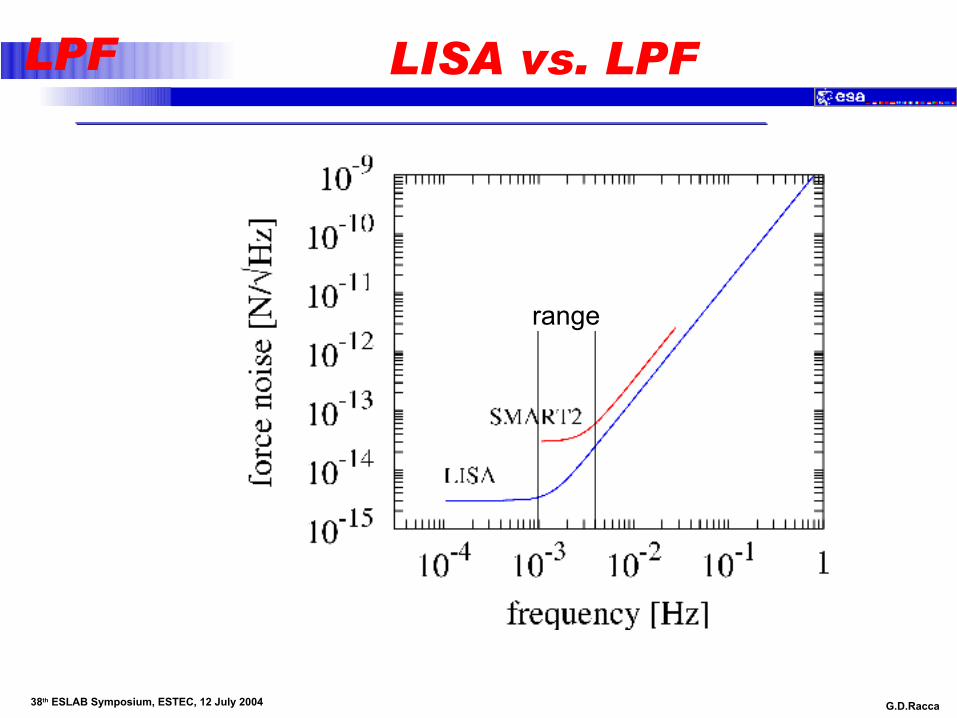
LPF LISA vs. LPF
range

G.D.Racca 38th ESLAB Symposium, ESTEC, 12 July 2004
LPF The Mother of all Noises
{ { {
}
{
Force on spacecraft
S C2T/ Mnoise p n 2
fbSensor noiseParasitic stiffnessForce on Test-Mass Drag free
gain
Relative diplacementTM wrt S/C
Ffa xm M
-
æ öç ÷ç ÷= + w +ç ÷wç ÷ç ÷è ø144424443

G.D.Racca 38th ESLAB Symposium, ESTEC, 12 July 2004
LPF Noise identification
IS readout displacement noise
Thermal effects
Cross – Talk
Electro-Magnetic disturbances generated within the spacecraft
Magnetic disturbances due to interplanetary field fluctuation
Random charging
Laser readout noise and thermal distortion
Laser radiation pressure fluctuation
Fluctuation of local gravitational field due to distortion of the system components

G.D.Racca 38th ESLAB Symposium, ESTEC, 12 July 2004
LPF Parasitic coupling
DC-voltage
AC-voltage
Charge
Magnetic stiffness
Gravitational gradient
Low frequency suspension
G.D.Racca 38th ESLAB Symposium, ESTEC, 12 July 2004
LPF Disturbance Forces
External Forces on the spacecraft include:
– Thruster force, including noise
– Difference in gravitational acceleration between test mass and spacecraft centre of mass
– Solar radiation pressure
– Interaction with planetary magnetic fields etc.
Internal Forces acting on the proof mass and the spacecraft include
– Thermal noise, radiation pressure
– Pressure fluctuations, outgassing
– Electrostatic, magnetic, gravitational fields
– Force that arises from sensor noise feeding into thruster commands and hence resulting in random thrust noise

G.D.Racca 38th ESLAB Symposium, ESTEC, 12 July 2004
LPF Operative Modes
Off Mode
Safe Mode
Positioning Mode
Accelerometer Mode
M1
M3
M4

G.D.Racca 38th ESLAB Symposium, ESTEC, 12 July 2004
LPF M1
The spacecraft follows TM1 along the sensitive axis, by using the capacitive sensor measurement.
TM2 is controlled along the sensitive axis by the electro-static suspension loop, by using the capacitive sensor measurement.
Other DoF are controlled by a combination of thrusters and electrostatic-suspension, in and out of band.
The main metrology signal is the relative position of TM1 vs. TM2 as measured by the interferometer.
TM1 and TM2 shall be interchangeable. Some test runs are required by using the interferometer output instead of the capacitive readouts.
G.D.Racca 38th ESLAB Symposium, ESTEC, 12 July 2004
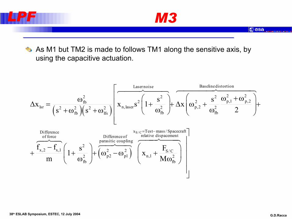
LPF M3
As M1 but TM2 is made to follows TM1 along the sensitive axis, by using the capacitive actuation.
( )( )
( )
BaselinedistortionLasernoise
2 22 2 2p,1 p,22 2fb
lsr n,laser p,22 22 2 2 2fb fbfb lfs
DifferenceDifferof force
2x,2 x,1 2 2
p2 p12fb
s sx x s 1 x2s s
f f s1m
éê æ öw +wæ öw êD = + + D w + +ç ÷ç ÷ ç ÷w w+w +w ê è ø è øêë
- æ ö+ + + w -wç ÷wè ø
644447444486447448
64748S / Cx Test mass / Spacecraft
relative dispacementenceofparasitic coupling
S/ Cn,1 2
fb
FxM
= - ùú
æ ö ú+ç ÷ úwè ø ú
úû
644744864748

G.D.Racca 38th ESLAB Symposium, ESTEC, 12 July 2004
LPF M4
xLTP
yLTP
yDRS
xDRS
45°
TM1DRS
TM2DRS
TM2LTP
TM1LTP

G.D.Racca 38th ESLAB Symposium, ESTEC, 12 July 2004
LPF M4
Drag free along the x-axis of the LTP is controlled by the LTP x-axis capacitive sensor readout of the LTP TM1 (actuation normal to the DRS x-axis).
Drag free along the x-axis of the DRS is controlled by the DRS x-axis capacitive sensor readout of the DRS TM1 (actuation normal to the LTP x-axis).
Attitude along f (rotation around the common z-axis) is controlled within the MBW by the differential y-axis output of the IS1 and IS2 of LTP.
TM1 and TM2 of the LTP are subject, along the y-axis, to a low frequency suspension loop driven by their common mode displacement.

G.D.Racca 38th ESLAB Symposium, ESTEC, 12 July 2004
LPF Test Runs
12 Main Runs. A Test Run is NOT a single demonstration sequence:1. Measurement of total acceleration (M1)
2. Measurement of acceleration noise (M3)
3. Measurement of internal forces (M1 and M3)
4. Measurement of stiffness (M3)
5. Measurement of cross-talk (M3)
6. Test of continuous charge charge measurement (M3)
7. Test of continuous discharge (M3)
8. Drift mode
9. Acceleration noise at different working points (M3)
10. Noise measurement below the MBW (M1)
11. Sensitivity to magnetic field and thermal gradient (M3)
12. Joint operations with the DRS
G.D.Racca 38th ESLAB Symposium, ESTEC, 12 July 2004
LPF Joint Operations
• Simultaneous operation of LTP and DRS at full functionality for both packages.
• Use of the DRS test masses as a source of gravitational signal for the LTP.
• Use of the LTP test masses as a source of gravitational signal for the DRS.
• 2-axes 2-test-masses control with full functionality for both packages and one axis controlled by DRS (mode M4).

G.D.Racca 38th ESLAB Symposium, ESTEC, 12 July 2004
LPF Mode Transition
Accelerometer Mode
M1-initM1-perf
M3
M1-optical M4 JointLISA Mode
Standard
FDIR
M1-drift
LTP Science Mode

G.D.Racca 38th ESLAB Symposium, ESTEC, 12 July 2004
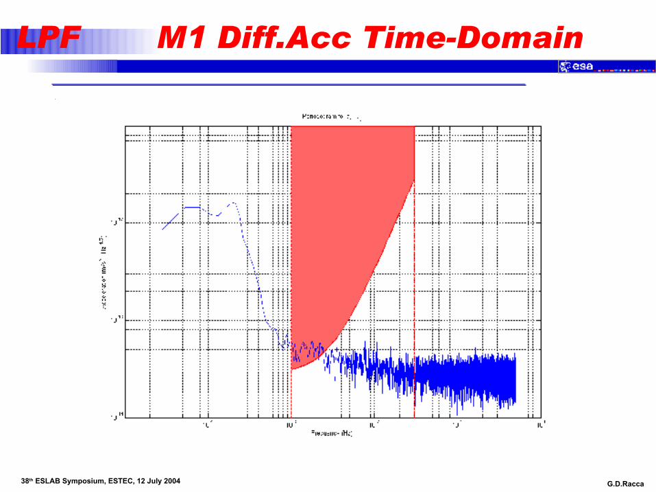
LPF M1 Differential Acceleration
Performance needs to be traded with robustness of x2 suspension controller
G.D.Racca 38th ESLAB Symposium, ESTEC, 12 July 2004
LPF M1 Diff.Acc Time-Domain
G.D.Racca 38th ESLAB Symposium, ESTEC, 12 July 2004
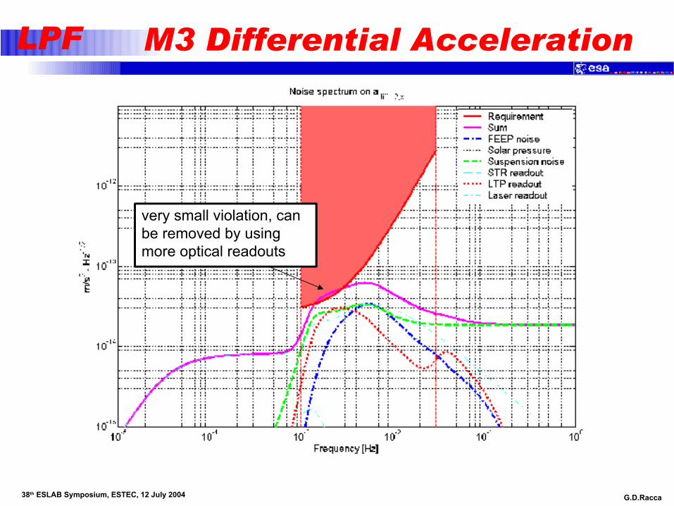
LPF M3 Differential Acceleration
very small violation, can be removed by using more optical readouts
LISA Pathfinder / SMART-2
Spacecraft Configuration
Material from Prime Contractor
EADS Astrium Ltd. (UK)

G.D.Racca 38th ESLAB Symposium, ESTEC, 12 July 2004
LPF System Overview
LISA Pathfinder Launch Composite consists of two modules
– Science Spacecraft– Propulsion Module
Current Predicted Maximum Mass is 1881.3 kg.
Maximum Launch Mass is 1910 kg (constrained by Rockot capability)
Overall dimensions are 2836 mm high (plus 276 mm protrusion into LVA) and 2100 mm diameter (plus 30 mm antenna protrusion beyond this)
Compliant with the envelopes of both Dnepr and Rockot

G.D.Racca 38th ESLAB Symposium, ESTEC, 12 July 2004
LPF The Science Spacecraft
The science spacecraft carries the the LTP and DRS, the micro-propulsion systems and the drag free control system. Total mass about 470kg
The inertial sensor core assemblies are mounted in a dedicated compartment within the central cylinder.
DRS Colloid thrusters are mounted on opposing outer panels.
Payload electronics and spacecraft units are accommodated as far away as possible from the sensors to minimise gravitational, thermal and magnetic disturbance.
The FEEP and cold-gas micro-propulsion assemblies are arranged to provide full control in all axes.

G.D.Racca 38th ESLAB Symposium, ESTEC, 12 July 2004
LPF Science Spacecraft
Central Cylinder 788 mm x 900 mm long mounting:-• the LTP Optical Bench and the DRS Sensor Assembly
• the Propulsion Module I/F
Eight Shear Walls 864 high, 571 or 510 wide mounting:-– LTP Electrical Boxes, DRS Electronics Assembly
– all subsystem elements not requiring external visibility
Eight External Walls 864 high mounting:-• the thruster assemblies (2 Collodial, 3 Cold Gas & 3 FEEP)
• the AOCS sensors (star trackers & eclipse detectors)
• Low Gain and Medium Gain antennas
Top Floor 2100 mounting Solar Array and Sun Sensors
Lower Closure Floors.
Central Cylinder, all panels carbon fibre skins, aluminium honeycomb cores for low mass, high stiffness, low distortion
Overall Dimensions 985 mm high, 2100 mm diameter (plus 30 mm antenna protrusion beyond this)
Current Predicted Maximum Mass 472.1 kg.
G.D.Racca 38th ESLAB Symposium, ESTEC, 12 July 2004
LPF Disturbance reduction
Disturbances on the science spacecraft to be actively minimised by design:
– No mechanisms on the science spacecraft
– Known mass
– No actively controlled thermal elements (does not preclude heaters, but does preclude thermostats)
– Fixed sunshield, limited solar aspect angle
– No liquids

G.D.Racca 38th ESLAB Symposium, ESTEC, 12 July 2004
LPF Managing Self gravity
DC force fields on spacecraft contribute to differential acceleration DC forces, stiffness and noise
The main internal contributors to the DC force are self-gravity, magnetic and electrostatic fields.
– Self gravity most difficult
Dedicated central compartment isolates DRS & LTP inertial sensors - DRS is largest disturbance on LTP
Compensation masses will be required inside LTP and DRS.
– Masses designed by PI for LTP & DRS at same time– Must be defined early
Gravitational modelling required– Detailed mass models of everything
Fix configuration and masses early– Spacecraft provides final compensation– Mass critical, so adding extra mass not an option
(image from Trento University:)

G.D.Racca 38th ESLAB Symposium, ESTEC, 12 July 2004
LPF Gravity Budget
Max differential acceleration between TMs specified in LTP Science Requirements (LTPA-UTN-ScRD-Iss002-Rev1)
Three main contributors are – the inertial sensor (IS), the LTP and the spacecraft (including DRS). DRS and LTP largest external contributors to each other.
Analysis performed using spreadsheet model & current spacecraft configuration shows uncompensated acceleration values about 3x10⁻⁸ m/s2 - will require compensation
Current requirements are:
Differential Acceleration due to gravity(m/s2) x 10-9
Axis Total IS LTP Spacecraft DFx/M 1.1 0.35 0.40 0.35 DFy/M 1.7 0.55 0.60 0.55 DFz/M 3.2 1.10 1.10 1.0
G.D.Racca 38th ESLAB Symposium, ESTEC, 12 July 2004
LPF Propulsion Module
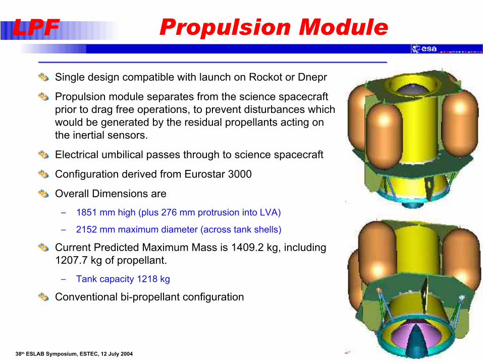
Single design compatible with launch on Rockot or Dnepr
Propulsion module separates from the science spacecraft prior to drag free operations, to prevent disturbances which would be generated by the residual propellants acting on the inertial sensors.
Electrical umbilical passes through to science spacecraft
Configuration derived from Eurostar 3000
Overall Dimensions are
– 1851 mm high (plus 276 mm protrusion into LVA)
– 2152 mm maximum diameter (across tank shells)
Current Predicted Maximum Mass is 1409.2 kg, including 1207.7 kg of propellant.
– Tank capacity 1218 kg
Conventional bi-propellant configuration
G.D.Racca 38th ESLAB Symposium, ESTEC, 12 July 2004
LPF Thermal design
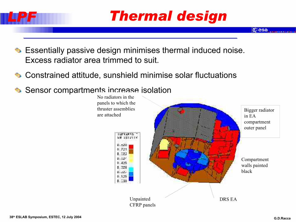
Essentially passive design minimises thermal induced noise. Excess radiator area trimmed to suit.
Constrained attitude, sunshield minimise solar fluctuations
Sensor compartments increase isolation
Compartment walls painted black
Unpainted CFRP panels
No radiators in the panels to which the thruster assemblies are attached
Bigger radiator in EA compartment outer panel
DRS EA
Compartment walls painted black
Unpainted CFRP panels
No radiators in the panels to which the thruster assemblies are attached
Bigger radiator in EA compartment outer panel
DRS EA

G.D.Racca 38th ESLAB Symposium, ESTEC, 12 July 2004
LPF Micro-Propulsion
LISA PF must prove the use of proportional micro-thrusters for precision drag free control in space.
A key element of the disturbance control system, they must meet stringent performance and stability requirements
– very low thrust (0.1 to 75 N in drag free modes)
– very low noise (target <1N/Hz)
– precisely controlled, low power
LISA PF enables the calibration of the thruster performance using the LTP as an accelerometer
FEEP and cold gas solutions under test by ESA
Field Emission Electric Propulsion thrusters
Micro-Cold Gas Thrusters
G.D.Racca 38th ESLAB Symposium, ESTEC, 12 July 2004
LPF Micro-propulsion (cont.’d)
FEEP’s use Indium or Caesium propellant– Issues with temperature (Indium) and reactivity (Caesium)– Must be liquid to operate (Indium must be heated)
High voltage power supplies
Noise performance may not be measurable– Nanobalance tests this year
Lifetime is a potential problem:– Indium FEEP’s failed life test on GOCE (although one thruster had
accumulated over 3000 hours by then)
– Caesium FEEP’s have not been fired for more than 500 hours
Cold gas Isp – 73 seconds with heated nozzle– Potentially 4.3 kg of propellant
– Distributed tankage to minimise gravitation effects
Cold gas thruster best considered as controlled leak– Able to operate up to 1mN for AOCS purposes

G.D.Racca 38th ESLAB Symposium, ESTEC, 12 July 2004
LPF FEEP EM
G.D.Racca 38th ESLAB Symposium, ESTEC, 12 July 2004
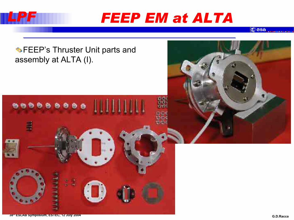
LPF FEEP EM at ALTA
FEEP’s Thruster Unit parts and assembly at ALTA (I).

G.D.Racca 38th ESLAB Symposium, ESTEC, 12 July 2004
LPF Micropropulsion thruster configuration
G.D.Racca 38th ESLAB Symposium, ESTEC, 12 July 2004
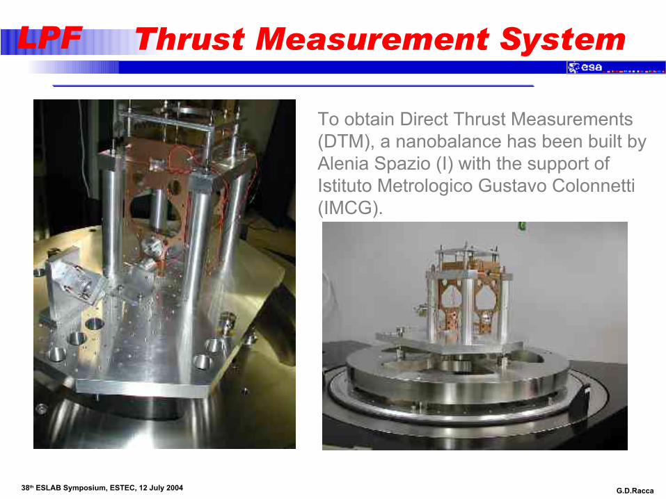
LPF Thrust Measurement System
To obtain Direct Thrust Measurements (DTM), a nanobalance has been built by Alenia Spazio (I) with the support of Istituto Metrologico Gustavo Colonnetti (IMCG).
G.D.Racca 38th ESLAB Symposium, ESTEC, 12 July 2004
LPF Mission Design
• mission requirements
• operational orbit
• transfer after launch by Rockot
G.D.Racca 38th ESLAB Symposium, ESTEC, 12 July 2004
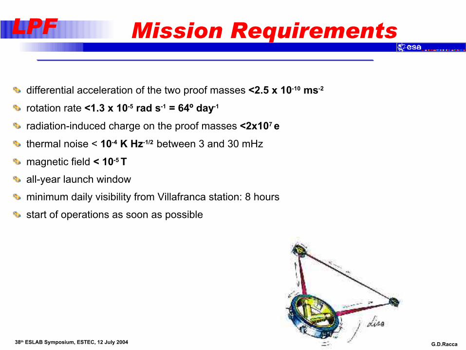
LPF Mission Requirements
differential acceleration of the two proof masses <2.5 x 10⁻¹⁰ ms-2
rotation rate <1.3 x 10⁻⁵ rad s-1 = 64º day-1
radiation-induced charge on the proof masses <2x10⁷ ethermal noise < 10-4 K Hz-1/2 between 3 and 30 mHz
magnetic field < 10-5 Tall-year launch window
minimum daily visibility from Villafranca station: 8 hours
start of operations as soon as possible

G.D.Racca 38th ESLAB Symposium, ESTEC, 12 July 2004
LPF Libration Orbits
• libration orbits are possible at the Lagrange points L1-5, where zero-velocity curves of the 3-body problem intersect
• L1 is located 1.5 million km from Earth in the direction towards the Sun (figure not to scale)

G.D.Racca 38th ESLAB Symposium, ESTEC, 12 July 2004
LPF Mission Sequence
The target orbit is at the Earth-Sun L1 Lagrange point.
For a 10 burn sequence, the total DeltaV is about 3150 m/sec, provided by the propulsion
stage
G.D.Racca 38th ESLAB Symposium, ESTEC, 12 July 2004
LPF operational orbit - type 1
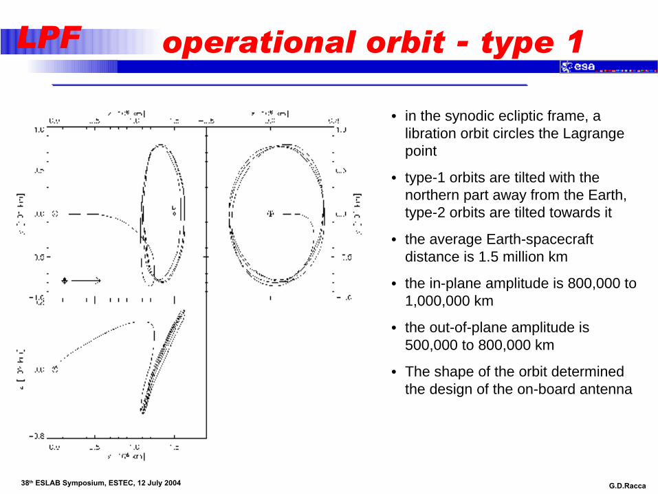
• in the synodic ecliptic frame, a libration orbit circles the Lagrange point
• type-1 orbits are tilted with the northern part away from the Earth, type-2 orbits are tilted towards it
• the average Earth-spacecraft distance is 1.5 million km
• the in-plane amplitude is 800,000 to 1,000,000 km
• the out-of-plane amplitude is 500,000 to 800,000 km
• The shape of the orbit determined the design of the on-board antenna
G.D.Racca 38th ESLAB Symposium, ESTEC, 12 July 2004
LPF operational orbit - type 2
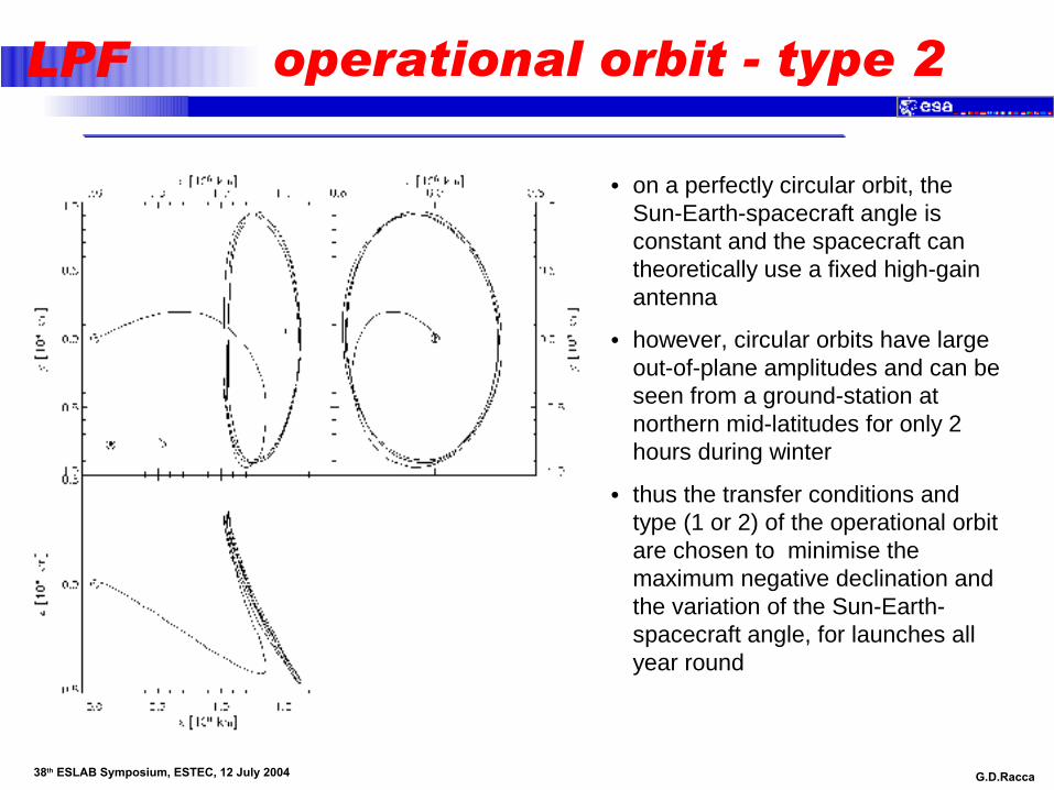
• on a perfectly circular orbit, the Sun-Earth-spacecraft angle is constant and the spacecraft can theoretically use a fixed high-gain antenna
• however, circular orbits have large out-of-plane amplitudes and can be seen from a ground-station at northern mid-latitudes for only 2 hours during winter
• thus the transfer conditions and type (1 or 2) of the operational orbit are chosen to minimise the maximum negative declination and the variation of the Sun-Earth-spacecraft angle, for launches all year round

G.D.Racca 38th ESLAB Symposium, ESTEC, 12 July 2004
LPF Transfer Sequence - Rockot
• initial parking orbit: 900x200km, 63º inclination
• a total Dv of more than 3 km s-1 is needed, which must be split in 11 individual manoeuvres in order to contain gravity loss
• between the manoeuvres there must be time for tracking, orbit determination, and commanding
• the total duration of the apogee-raise sequence is 9 days

G.D.Racca 38th ESLAB Symposium, ESTEC, 12 July 2004
LPF Mission Design Summary
launch by Rockot in early 2008 into a slightly elliptic low Earth orbit with an inclination of 63°
the orientation of the line of apsides of the parking orbit must be adjusted to target for an operational orbit that fulfils the station visibility constraints
a sequence of 11 manoeuvres brings the spacecraft to a transfer towards L1, the Sun-facing Lagrange point of the Sun-Earth system, 1.5 million km from Earth
depending on the launch date, the operational orbit is a type-1 or type-2 Lissajous orbit in order to achieve a minimum of 8 hours of visibility from the ground-station in Villafranca

LISA Pathfinder / SMART-2
Payload Interfaces
G.D.Racca 38th ESLAB Symposium, ESTEC, 12 July 2004
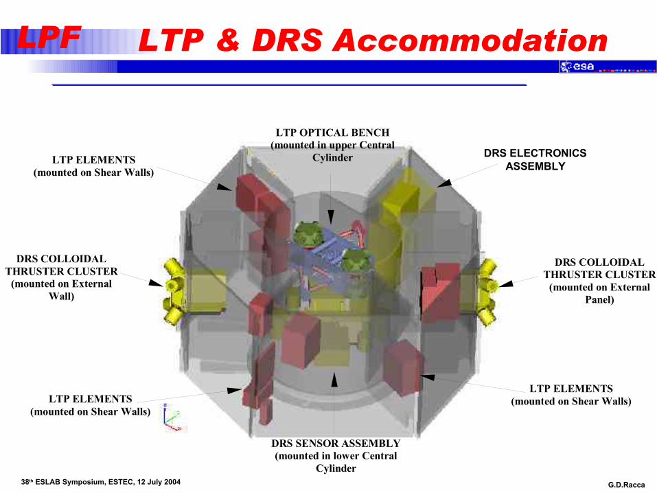
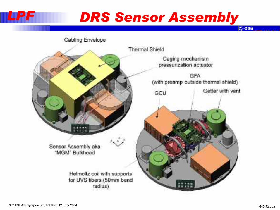
LPF LTP & DRS Accommodation
DRS SENSOR ASSEMBLY (mounted in lower Central
Cylinder
DRS ELECTRONICS ASSEMBLY
DRS COLLOIDAL THRUSTER CLUSTER
(mounted on External Panel)
LTP OPTICAL BENCH (mounted in upper Central
Cylinder
DRS COLLOIDAL THRUSTER CLUSTER
(mounted on External Wall)
LTP ELEMENTS (mounted on Shear Walls)
LTP ELEMENTS (mounted on Shear Walls)
LTP ELEMENTS (mounted on Shear Walls)

G.D.Racca 38th ESLAB Symposium, ESTEC, 12 July 2004
LPF LTP Accommodation
The LTP consists of the following assemblies– the Optical Bench– a Power Control Unit/Data Management Unit – two Front End Electronics SAU– a Charge Management System UV Lamp Assembly– a Charge Management Electronics Assembly– a Phase Meter– a Laser– a Modulation Bench– diagnostic probes (solar pressure sensors, magnetometer & particle
detector)
LTP Optical Bench is mounted in the Central Cylinder between two Shear Panels
– Mounted on 8 glass fibre struts (likely to change)– Symmetric mounting to minimise gravitational and thermal
asymmetries
The remaining LTP Elements are distributed around the Shear and External Walls to minimise the overall gravitation disturbance
G.D.Racca 38th ESLAB Symposium, ESTEC, 12 July 2004
LPF DRS Accommodation
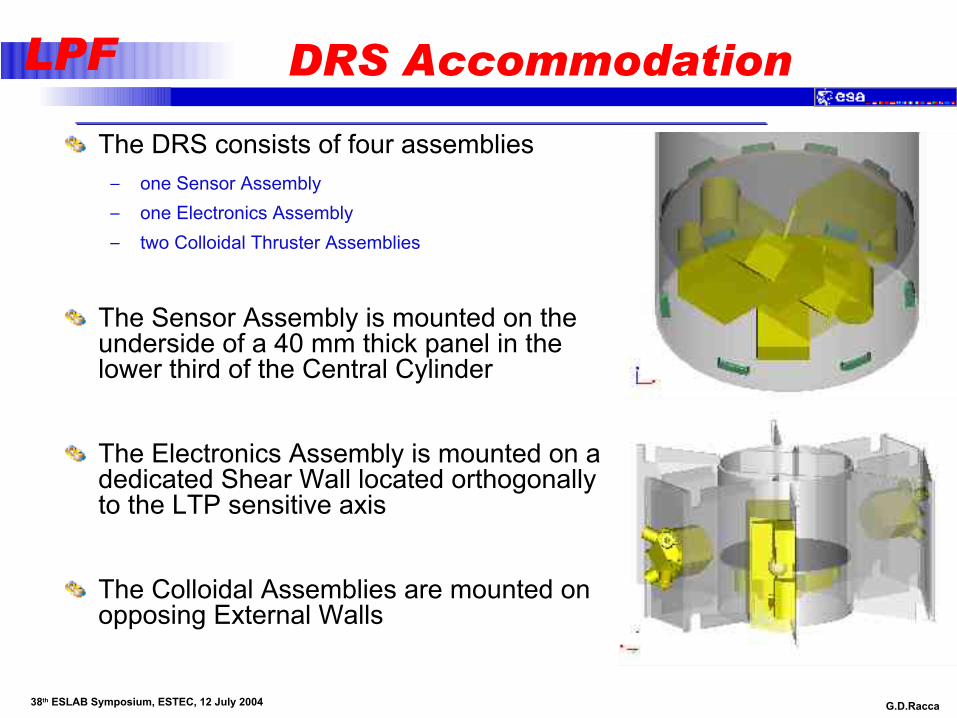
The DRS consists of four assemblies– one Sensor Assembly– one Electronics Assembly– two Colloidal Thruster Assemblies
The Sensor Assembly is mounted on the underside of a 40 mm thick panel in the lower third of the Central Cylinder
The Electronics Assembly is mounted on a dedicated Shear Wall located orthogonally to the LTP sensitive axis
The Colloidal Assemblies are mounted on opposing External Walls
G.D.Racca 38th ESLAB Symposium, ESTEC, 12 July 2004
LPF DRS Sensor Assembly

G.D.Racca 38th ESLAB Symposium, ESTEC, 12 July 2004
LPF DRS Thrusters & Electronics
Colloidal ThrusterAssembly
ElectronicsAssembly
LISA Pathfinder / SMART-2
The LISA Test-flight Package

G.D.Racca 38th ESLAB Symposium, ESTEC, 12 July 2004
LPF The LTP architecture
G.D.Racca 38th ESLAB Symposium, ESTEC, 12 July 2004
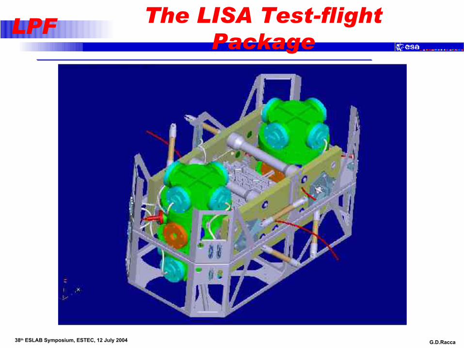
LPF The LISA Test-flight Package

G.D.Racca 38th ESLAB Symposium, ESTEC, 12 July 2004
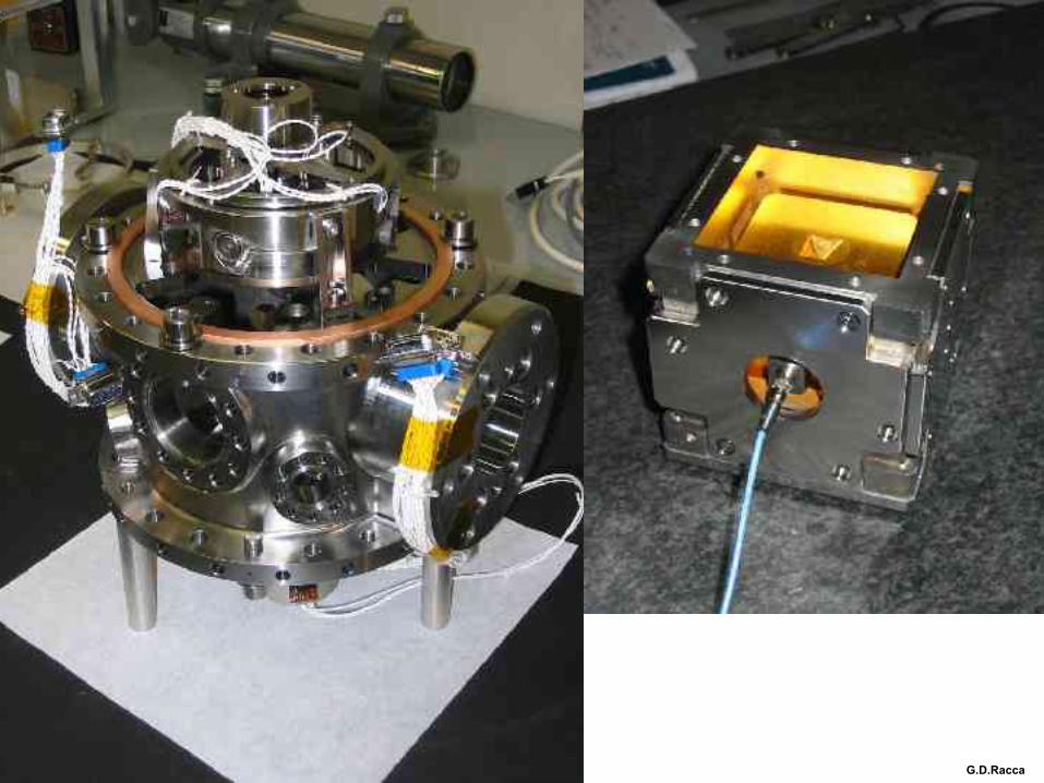
LPF The LTP EM

G.D.Racca 38th ESLAB Symposium, ESTEC, 12 July 2004
LPF
Test-mass
Vacuum enclosure
Electrode Housing
Optical Window
Caging Mechanism
UV Optical Fibres for
Discharging
G.D.Racca 38th ESLAB Symposium, ESTEC, 12 July 2004
LPF

G.D.Racca 38th ESLAB Symposium, ESTEC, 12 July 2004
LPF The LTP Optical Bench
G.D.Racca 38th ESLAB Symposium, ESTEC, 12 July 2004
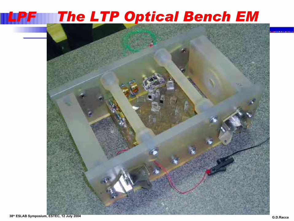
LPF The LTP Optical Bench EM
G.D.Racca 38th ESLAB Symposium, ESTEC, 12 July 2004
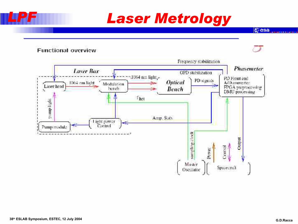
LPF Laser Metrology

G.D.Racca 38th ESLAB Symposium, ESTEC, 12 July 2004
LPF
Laser

G.D.Racca 38th ESLAB Symposium, ESTEC, 12 July 2004
LPF

G.D.Racca 38th ESLAB Symposium, ESTEC, 12 July 2004
LPF

G.D.Racca 38th ESLAB Symposium, ESTEC, 12 July 2004
LPF

G.D.Racca 38th ESLAB Symposium, ESTEC, 12 July 2004
LPF

G.D.Racca 38th ESLAB Symposium, ESTEC, 12 July 2004
LPF
G.D.Racca 38th ESLAB Symposium, ESTEC, 12 July 2004
LPF

G.D.Racca 38th ESLAB Symposium, ESTEC, 12 July 2004
LPF

G.D.Racca 38th ESLAB Symposium, ESTEC, 12 July 2004
LPF
G.D.Racca 38th ESLAB Symposium, ESTEC, 12 July 2004
LPF

G.D.Racca 38th ESLAB Symposium, ESTEC, 12 July 2004
LPF LTP schedule (1)

G.D.Racca 38th ESLAB Symposium, ESTEC, 12 July 2004
LPF LTP schedule (2)
G.D.Racca 38th ESLAB Symposium, ESTEC, 12 July 2004
LPF
2003 2004 2005 2006 2007 2008F M A M J J A S O N D J F M A M J J A S O N D J F M A M J J A S O N D J F M A M J J A S O N D J F M A M J J A S O N D J F M A M J J A S O N DJ
MILESTONES24
SRR23
PDR30
HDR21
CDR21
FAR11
LRR04
IOCR21
FRR17
LAUNCH
LTP EM AIV06 07
OB TB/TV & Perform ance Test10 01
LTP EM Delta Qual'n25
LTP EM Delivery29 26
IS EM Vibration test16 07
OMS AIT @ASD10 10
LTP Ground Test08 26
LTP EM Integration27 24
LTP EM Tests @ ASD
LTP FM AIV10 15
OB Design Update01 15
Interferometer AIT29 30
LTP Integration & Test26 31
OB FM AIT16 28
LCA AIT30
LTP FM Delivery
DRS FM AIV03 26
EID-A Interaction14
Project CDR02 04
EID-B Interaction01 30
DRS Integration & Test31
DRS FM Delivery
Real Time bench22 16
SVF 1 Phase 116
EM LTP30 15
FM LTP Early and Late Deliveries25
17 14E2E RTB Phase 1
02 27E2E RTB Phase 3
15 18E2E RTB Phase 2
2501Integrate FM LTP to RTB
0422E2E RTB Phase 4
Spacecraft AIV12
Prop. M odule Structure1620
Mate Sci S/C and Prop'n Module12 18
Propulsion & Science Module Assembly & Test1303
SPT-1 E2E21 15
Propulsion Module0410
S/C Mass Properties21 03
Science Spacecraft25
FM LTP05 03
Electrical & Functional Tests
Launch Composite11 20
1115Re-integrate Science Module to Propulsion Module
3106SVT-2
2228Pack & Ship to Launch-site
2602SVT-1
0720S/C Alignment & Mass Properties
Launch Campaign30 20
3008Set-UP & Elect. IST
0517Combined Operations
2126Fuel S/C
17Launch
LISA PATH FINDERM ANAGEM ENT AIV-SUM M ARY SCHEDULE
Planned
In Progress
Com pleted
Previous Plan (Back)Current Plan (Front)
Delivery(with current date)
Milestone or Event(with current date)
Legend:
Lisa Pathfinder Project Office
ESA/ESTECScientific Projects Department
Schedule Information:- Status- Issue No.- Distribution
i:\scs\jaap\sm art-2\s2-arp\LP_AIV-Sum -03.avfi:\scs\jaap\sm art-2\s2-arp\LP_AIV-Sum -03.arp
Draft - 1c:::
1.03
Project.Man.
Prepared by
Status date
Issue date
:
::
:
Giuseppe Racca
Jaap de Bijl
19-MAR-2004Print date:19-MAR-2004 Page: 1 1of
AIV Manager: Eliseo Balaguer
01-MAR-200427
27
17:47/
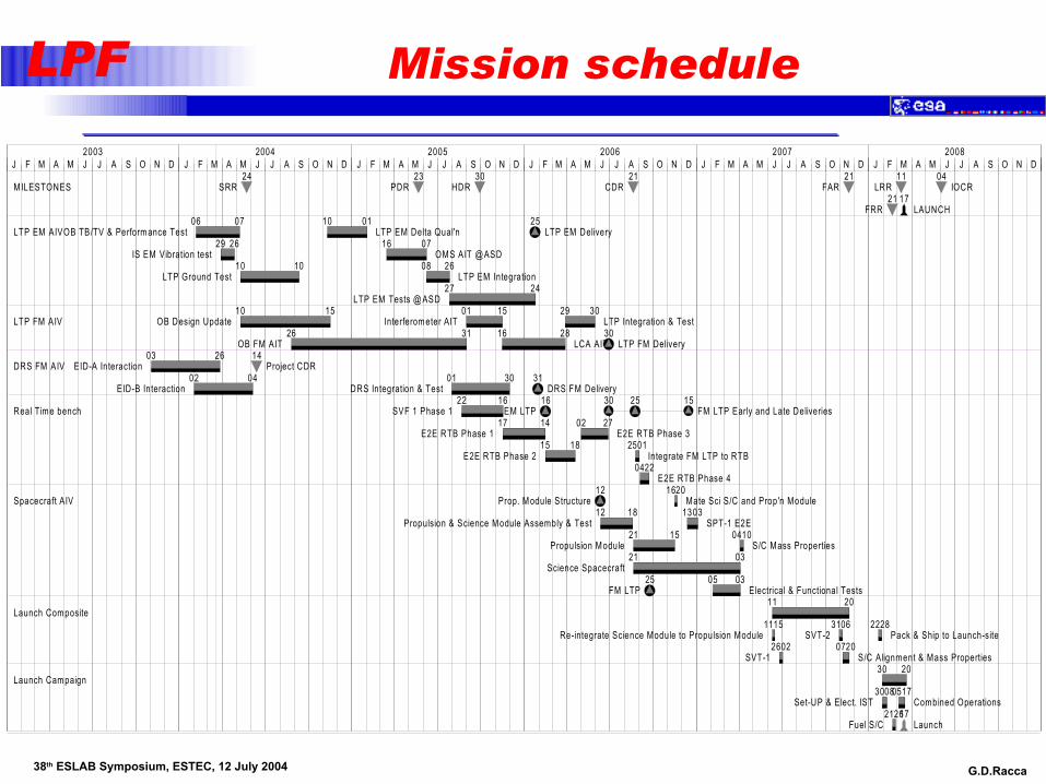
Mission schedule

G.D.Racca 38th ESLAB Symposium, ESTEC, 12 July 2004
LPF Key engineering milestones
System specifications preparation => SRR (May 04)
LTP & DRS EID-A/B finalisation => August 04
Subsystem specifications => ITT (June 04-March 05)
Engineering Analyses through to PDR (May 05)
Hardware Design Review to start RTB test (Oct 05)
End of RTB test and design phase => CDR (Aug 06)
LPT integration in FM (Sep 06)
Electrical and Functional tests (Jan-Mar 07)
Environmental Tests (Jun-Nov 07)
Launch Campaign (Feb-Mar 08)
Launch (Mar 08)
In Orbit Commissioning Review (May 08)