lit2626 r1 carco hch100-installation&parts...
TRANSCRIPT

1
®
LIT262611/2013PRINTED IN U.S.A. P.O. Box 547 Broken Arrow, OK 74013
Tel 918-251-8511 / Fax 918-259-1575
www.paccarwinch.com
WINCH
2
Model Number and Serial Number...........................................................3Tractor Conversion Group .....................................................................4-5Mounting Group .....................................................................................6-7Lines Group ...........................................................................................8-9Common Parts ..................................................................................10-11Brake Assembly ................................................................................12-13Drive Input Assembly ............................................................................. 14Sprag Clutch Assembly .......................................................................... 15Right Angle Assembly .......................................................................16-17Hydraulic Motor Sub-Assembly .............................................................. 18Metric Conversion Table ........................................................................ 19

3
When information on a hoist is needed, always refer to the model number and serial number. Both arelocated on the top of the motor side end plate as indicated above.
The following service instructions have been prepared to provide assembly, disassembly and maintenanceinformation for the CARCO Model HCH100 Tractor Winch. It is suggested that before doing any work on theseunits, all assembly and disassembly instructions should be read and understood.Some pictures in this manual may show details or attachments that are different from your unit . Also, somecomponents have been removed for illustrative purposes.Continuing product improvement may cause changes in your unit, which are not included in this manual .Whenever a question arises regarding your CARCO winch or this manual, please contact CARCO TechnicalSupport Department for the latest available information at P. O. Box 547, Broken Arrow, Oklahoma 74013,918r251r8511, 08:00r16:30 hours, CT, Monday through Friday.
DATA PLATE
HCH 100 — 207 V 087 — 04
POWER
DRUM
MAX
RATING
GEAR
RATIO
MOTOR
TYPE
MOTOR
SIZE*
DRUM
CODE
CHARACTER DESIGNATION
HCH HIGH-CAPACITY HYDRAULIC WINCH
100 MAXIMUM RATED FIRST-LAYER LINE PULL CAPACITY, LB (X 1,000)
207 TOTAL GEAR REDUCTION RATIO (207:1)
V V=VARIABLE-DISPLACEMENT PISTON MOTOR
087HYDRAULIC MOTOR DISPLACEMENT, CU INCHES/REV
FIGURES SEPARATED BY “/ “ INDICATE TWO-SPEED MOTOR
4
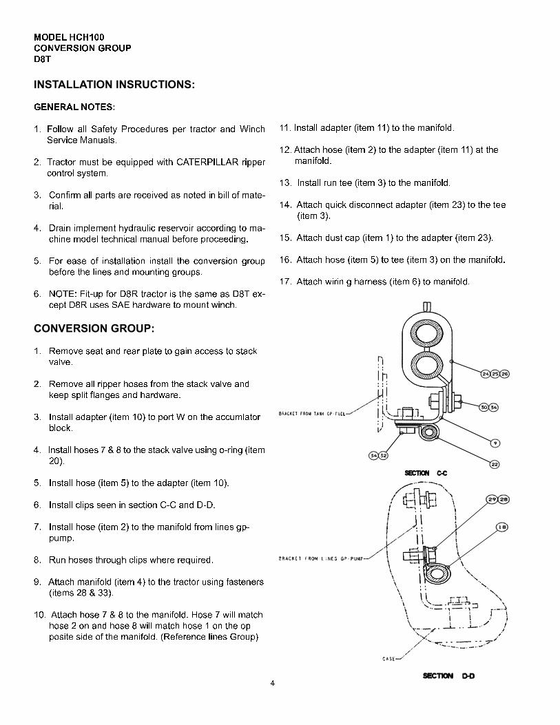
MODEL HCH100CONVERSION GROUPD8TGENERAL NOTES:1. Follow all Safety Procedures per tractor and WinchService Manuals.2. Tractor must be equipped with CATERPILLAR rippercontrol system.3. Confirm all parts are received as noted in bill of mateµrial.4. Drain implement hydraulic reservoir according to maµchine model technical manual before proceeding.5. For ease of installation install the conversion groupbefore the lines and mounting groups.6. NOTE: Fitµup for D8R tractor is the same as D8T exµcept D8R uses SAE hardware to mount winch.1. Remove seat and rear plate to gain access to stackvalve.2. Remove all ripper hoses from the stack valve andkeep split flanges and hardware.3. Install adapter (item 10) to port W on the accumlatorblock.4. Install hoses 7 & 8 to the stack valve using oµring (item20).5. Install hose (item 5) to the adapter (item 10).6. Install clips seen in section CµC and DµD.7. Install hose (item 2) to the manifold from lines gpµpump.8. Run hoses through clips where required.9. Attach manifold (item 4) to the tractor using fasteners(items 28 & 33).10. Attach hose 7 & 8 to the manifold. Hose 7 will matchhose 2 on and hose 8 will match hose 1 on the opposite side of the manifold. (Reference lines Group)
11. Install adapter (item 11) to the manifold.12.Attach hose (item 2) to the adapter (item 11) at themanifold.13. Install run tee (item 3) to the manifold.14. Attach quick disconnect adapter (item 23) to the tee(item 3).15. Attach dust cap (item 1) to the adapter (item 23).16. Attach hose (item 5) to tee (item 3) on the manifold.17. Attach wirin g harness (item 6) to manifold.
5
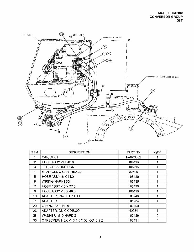
MODEL HCH100CONVERSON GROUPD8T
ITEM DESCRIPTION PART N0. QTY1 CAP, DUST PA6V0852 12 HOSE ASSY ö8 X 43.0 106118 13 TEE, ORFS/ORD RUN 106115 14 MANIFOLD & CARTRIDGE 82596 15 HOSE ASSY ö6 X 44.0 106139 16 W IRING HARNESS 106135 17 HOSE ASSY ö16 X 37 .0 106120 18 HOSE ASSY ö16 X 40.0 106119 110 ADAPTER, ORS STR THD 100946 111 ADAPTER 101284 120 OöRING, ö219 N 90 102199 423 ADAPTER, QUICK DISCO 40034 128 WASHER, M10 HARD Z 102126 633 CAPSCREW HEX M10ö1.5 X 30 GD10.9 Z 106131 4

66
MODEL HCH100MOUNTING GROUPD8T
ITEM DESCRIPTION PART N0. QTY1 BRACKET, MOUNTING 110017 12 CAPSCREW, HEX M30 X 3.5 X 90 GD10.9 Z 104193 143 WASHER, M30 HARD Z 104194 144 CAPSCREW, HEX 1 1/276 X 4.5 GD8 Z 104515 85 WASHER, 1 1/2 HARD Z 102886 8
X14
X8
7
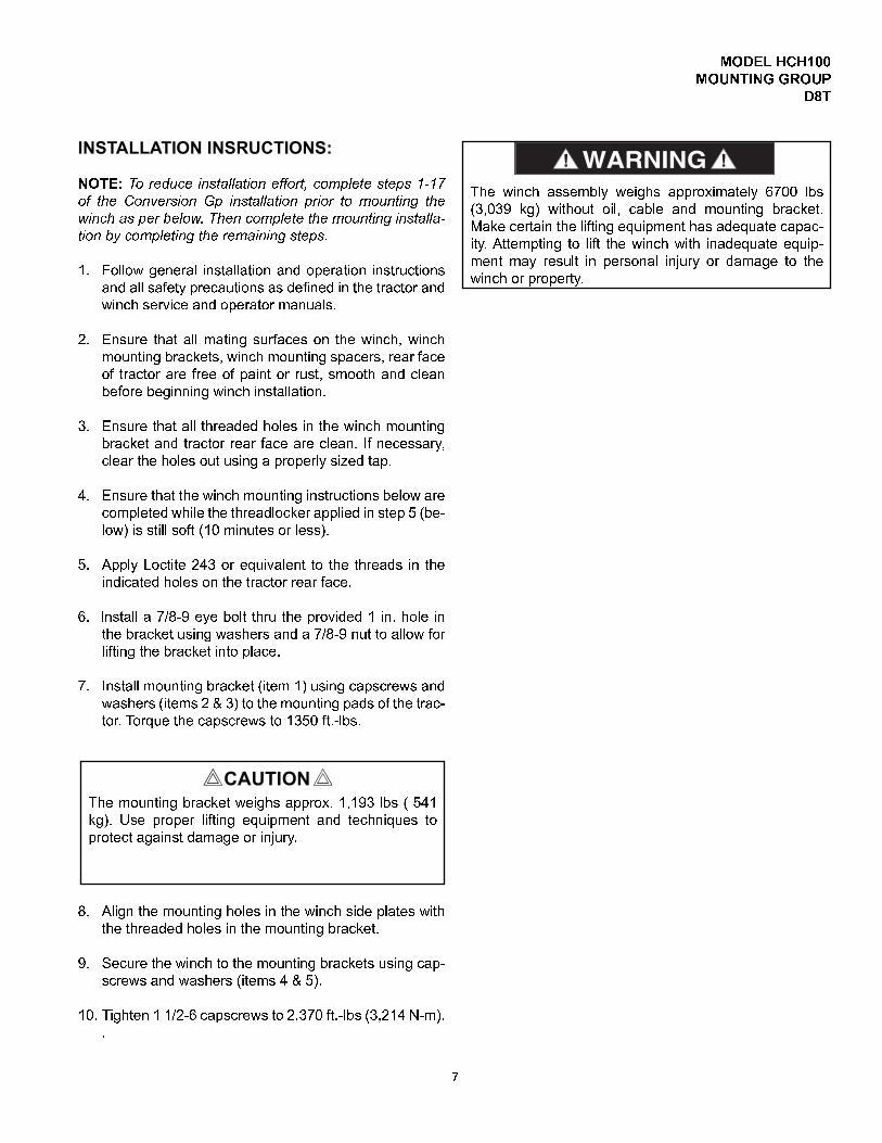
NOTE: To reduce installation effort, complete steps 1V17of the Conversion Gp installation prior to mounting thewinch as per below. Then complete themounting installaVtion by completing the remaining steps.1. Follow general installation and operation instructionsand all safety precautions as defined in the tractor andwinch service and operator manuals.2. Ensure that all mating surfaces on the winch, winchmounting brackets, winch mounting spacers, rear faceof tractor are free of paint or rust, smooth and cleanbefore beginning winch installation.3. Ensure that all threaded holes in the winch mountingbracket and tractor rear face are clean. If necessary,clear the holes out using a properly sized tap.4. Ensure that the winch mounting instructions below arecompleted while the threadlocker applied in step 5 (be�low) is still soft (10 minutes or less).5. Apply Loctite 243 or equivalent to the threads in theindicated holes on the tractor rear face.6. Install a 7/8�9 eye bolt thru the provided 1 in. hole inthe bracket using washers and a 7/8�9 nut to allow forlifting the bracket into place.7. Install mounting bracket (item 1) using capscrews andwashers (items 2 & 3) to the mounting pads of the trac�tor. Torque the capscrews to 1350 ft .�lbs.8. Align the mounting holes in the winch side plates withthe threaded holes in the mounting bracket.9. Secure the winch to the mounting brackets using cap�screws and washers (items 4 & 5).10. Tighten 1 1/2�6 capscrews to 2,370 ft .�lbs (3,214 N�m)..
MODEL HCH100MOUNTING GROUPD8TThe winch assembly weighs approximately 6700 lbs(3,039 kg) without oil, cable and mounting bracket.Make certain the lifting equipment has adequate capac�ity. Attempting to lift the winch with inadequate equip�ment may result in personal injury or damage to thewinch or property.
The mounting bracket weighs approx. 1,193 lbs ( 541kg). Use proper lifting equipment and techniques toprotect against damage or injury.CAUTION

8
1. Follow all safety procedures per the tractor and winchmaintenance and service manuals.2. Refer to page 9 for material list .3. To reduce installation effort install tractor conversiongroup prior to the mounting group and lines group.
1. Attach hose (item 2) to the ReelÄin port on the brakevalve using split flange kit (item 4) and elbow (item7). Attach the opposite end of hose to to manifold topright port using split flange kit (item 35).2. Attach hose (item 1) to the reelÄout port, which is loÄcated opposite brake valve using split flange kit (item4).Attach the opposite end of hose to the manifold topleft port using split flange kit (item 35).
3. Take cap off the tee in the case drain of the motor andconnect hose (item 3) to the tee. Install the adapter(item 28) to the manifold and attach to opposite endof hose (item 3) to the adapter.4. Attach hose (item 27) to the motor shift adapter. InÄstall adapter to the bottom of manifold (item 26) andconnect opposite end of hose (item 27) to adaptÄer.5. Verify all hose connections are tight BEFORE startÄing the tractor engine. Repair any leaks or damagedcomponents or fittings immediately.6. Ensure all tractor covers or previously removed partsare properly reinstalled.7. Check the tractor hydraulic tank to ensure proper oillevel . Refill as required.8. Check the winch gear oil level BEFORE operating thewinch. Fill as required with the proper gear oil .Fill the winch to the proper level with the recommendedoil BEFORE operating.Component damage may occurif the winch is operated without oil .CAUTION
28 26353 2721
MODEL HCH100LINES GROUPD8T

9
ITEM DESCRIPTION PART N0. QTY1 HOSE ASSY �20CD62/�16CD61 45 x 44 in . 110036 12 HOSE ASSY �20 ORFS/�16CD61 45 x 56 in . 110037 13 HOSE ASSY �8 X 49 .50 101266 14 SPL IT FLANGE K IT , 1.25 CODE 62 108935 27 ELBOW 90 �20 ORFS/�20 CD62 SF 110039 126 ADAPTER, 90 ELBOW �4 ORS/ORB 27430 127 HOSE ASSY, �4 X 41.50 , ORFS 103709 128 ADAPTER 101284 135 SPL IT FLANGE K IT, 1.0 CODE 61 62702 2
MODEL HCH100LINES GROUPD8T

10
MODEL HCH100COMMON PARTSGROUPD8T
222332

11
ITEM DESCRIPTION PART N0. QTY1 SIDEPLATE, SUPPORT END 103509 12 COVER, SIDEPLATE 103069 13 LOCKWASHER 3/8 27152 64 CAPSCREW HEX 3/8b16 X 1.0 GD8 Z 104309 65 GREASE FITTING 18047 16 SUPPORT SHAFT 104375 17 FILLbVENT PLUG 29678 18 VENT RELIEF VALVE 1b5 PSI 10074 19 ObRING 72109 110 BEARING, SPHERICAL ROLLER 103064 211 LIPSEAL 103085 212 WASHER HARD 1.0 101205 4013 CAPSCREW HEX 1b8 X 3.5 GD8 Z 103580 2414 CABLE DRUM ASSEMBLY 109968 116 DRIVE SHAFT 104376 117 ObRING 26373 118 CAPSCREW HEX 1b8 X 3.0 GRD8 Z 102597 1619 LOCKWASHER 9/16 Z Split 24128 1020 CAPSCREW HEX 9/16b12 X 1.5 GD8 Z 26396 1022 NUT, HEX 3/4 b10 GD8 Z 109884 423 LOCKWASHER 3/4 Z Split 13435 825 CAPSCREW HEX 3/4b10 X 2.5 GD8 Z 78453 2826 LOCKWASHER 3/4 Z Split 13435 2827 PIN, DOWEL 26667 828 TIEPLATE, UPPER 109969 129 SIDEPLATE, DRIVE END 102855 131 TIEPLATE, LOWER 109970 132 STUD, 3/4b10 X 29890 433 NUTbJAM 3/4b10 11791 234 STRAIGHT ADAPTER b6 JIC TO b8 ORB 26891 135 UNION,90 DEG. b6 JIC 31426 236 ELBOW, 45 DEG. b6 JIC 27149 137 FITTINGbCAP b6 JIC 75281 166 NAMEPLATE 76381 167 DRIVE SCREW 11842 4100 DRIVE GROUP, SEE PG. 14 63441 1200 INPUT ASSY, SEE PG. 16 & 17 83163 1300 BRAKE, SEE PG. 12 & 13 83194 1400 HYD MOTOR SUB ASSY, SEE PG. 18 84382 1500 FLUSHING FITTING ASSY 83200 1
COMMON PARTS GROUP
MODEL HCH100COMMON PARTSGROUPD8T

12
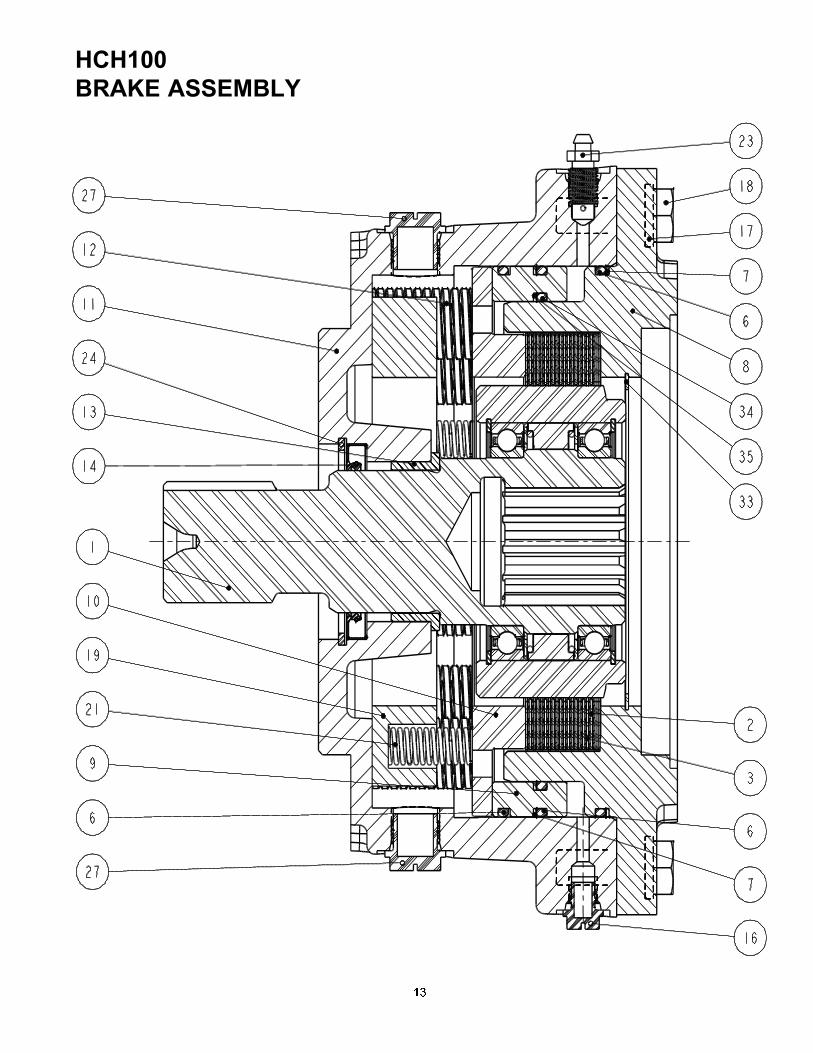
ITEM DESCRIPTION PART NO. QTY1 Brake Clutch Assembly SAE D SHAFT SEE PG. 15 83182 12 Friction Brake Disc 104138 93 Steel Brake Disc 102954 126 Oring 102271 37 Backup Ring 102272 28 Motor Adapter SAE 4 Bolt D 103884 19 Piston 100030 110 Pressure Plate 103850 111 Brake Housing 104603 112 Spring 27444 1213 Bushing 27367 114 Lip Seal 27644 116 Shipping Plug 25403 117 Lockwasher, 1/2 Z 11026 818 Capscrew, Hex 1/213 X 1.5 GD8 Z 104322 819 Spring Separator 52998 121 Spring 11310 323 Brake Bleeder 27472 124 Retaining Ring 25700 127 Shipping Plug 29964 233 Retaining Ring 103882 134 Oring 100032 135 Backup Ring 100033 1
13
14
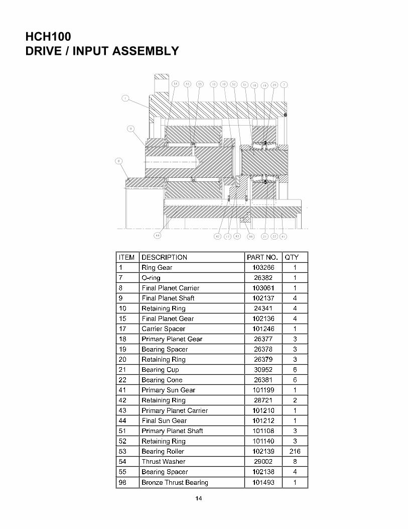
ITEM DESCRIPTION PART NO. QTY1 Ring Gear 103266 17 OÙring 26382 18 Final Planet Carrier 103061 19 Final Planet Shaft 102137 410 Retaining Ring 24341 415 Final Planet Gear 102136 417 Carrier Spacer 101246 118 Primary Planet Gear 26377 319 Bearing Spacer 26378 320 Retaining Ring 26379 321 Bearing Cup 30952 622 Bearing Cone 26381 641 Primary Sun Gear 101199 142 Retaining Ring 28721 243 Primary Planet Carrier 101210 144 Final Sun Gear 101212 151 Primary Planet Shaft 101108 352 Retaining Ring 101140 353 Bearing Roller 102139 21654 Thrust Washer 29002 855 Bearing Spacer 102138 498 Bronze Thrust Bearing 101493 1

15
ITEM DESCRIPTION PART N0. QTY/PER49 OUTER RACE NSS 154 RETAINING RING 103110 253 BALL BEARING 103104 252 OVERRUNNING CLUTCH NSS 11 BRAKE SHAFT (D�D BRA NSS 1NSS � NOT SERVICED SEPARATELY

16
RIGHT ANGLE ASSEMBLY

17
ITEM DESCRIPTION PART N0. QTY10 SPLINEADAPTER 40201 18 RING, RETAINING 27441 19 SPIRAL BEVELGEARSET 40131 114 O=RING 22721 115 MOTORADAPTER 40199 116 BEARING CUP 27447 217 BEARING CONE 27448 221 BEARING CUP 27445 222 BEARING CONE 27446 123 BEARING CONE 27410 124 PINION 29740 125 BULLGEAR 29741 126 CAPSCREW HEX 7/16=14 X 1GRD8 26395 327 .035 SOFT STEELWIRE 94058 .5 ft .28 RETAINER PLATE 26394 129 BEARING ASSY 26393 130 HOUSING, INPUT 104612 131 CAPSCREW HEX 1/2=13 X 1.5 GD8 Z 104322 1932 LOCKWASHER 11026 1933 O=RING 25108 134 COVER 27438 139 O=RING 10052 140 VENT RELIEFVALVE 1=5 PSI 10074 142 MAGNETIC PLUG 1/4=18 100125 243 MAGNETIC 1/2=14 72215 544 REDUCER BUSHING 18066 147 SHIM .003 (.0762 MM) 27462 248 SHIM .005 (.127 MM) 27463 149 SHIM .015 (.381MM) 27464 250 SHIM .003 (.0762 MM) 27465 151 SHIM .005 (.127 MM) 27466 252 SHIM .015 (.381MM) 27467 153 SHIM .003 (.0762 MM) 27468 154 SHIM .005 (.127 MM) 27469 255 SHIM .015 (.381MM) 27470 256 PROTECTORSAE "D" 100622 159 SHIM .030 (.762 MM) 29374 260 SHIM .030 (.762 MM) 29373 177 SPACER 27443 178 SPACER 40210 079 SPACER 40211 080 SPACER 40212 086 SHAFT, BULLGEAR 29247 1
RIGHT ANGLE ASSEMBLY
18
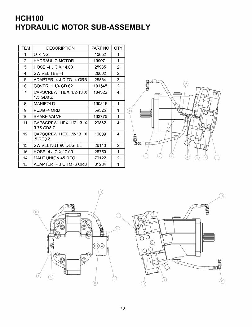
ITEM DESCRIPTION PART NO QTY1 O^RING 10052 12 HYDRAULIC MOTOR 109971 13 HOSE ^4 JIC X 14.00 25935 24 SWIVEL TEE ^4 26002 25 ADAPTER ^4 JIC TO ^4 ORB 25864 36 COVER, 1 1/4 CD 62 101545 27 CAPSCREW HEX 1/2^13 X1.5 GD8 Z 104322 48 MANIFOLD 100846 19 PLUG ^4 ORB 69325 110 BRAKE VALVE 103775 111 CAPSCREW HEX 1/2^13 X3.75 GD8 Z 29862 412 CAPSCREW HEX 1/2^13 X.5 GD8 Z 10009 413 SWIVEL NUT 90 DEG. EL 26140 216 HOSE ^4 JIC X 17.00 25750 114 MALE UNION 45 DEG. 70122 215 ADAPTER ^4 JIC TO ^6 ORB 31284 1

19
inches (in.) X 25.4 = millimeters (mm) millimeters (mm) X 0. 3937 = inches (in.)
feet (ft.) X 0.3048 = meters (m) meters (m) X 3.281 = feet (ft.)
miles (mi.) X 1.6093 = kilometers (km) kilometers (km) X 0.6214 = miles (mi.)
inches2 (sq.in.) X 645.15 = millimeters 2 (mm2) millimeters2 (mm2) X 0.000155 = inches2 (sq.in.)
feet2 (sq.ft.) X 0.0929 = meters2 (m2) meters2 (m2) X 10.764 = feet2 (sq.ft.)
inches3 (cu.in.) X 0.01639 = liters (l) liters (l) X 61.024 = inches3 (cu.in.)
quarts (qts.) X 0.94635 = liters (l) liters (l) X 1.0567 = quarts (qts.)
gallons (gal.) X 3.7854 = liters (l) liters (l) X 0.2642 = gallon (gal.)
inches3 (cu.in.) X 16.39 = centimeters3 (cc) centimeters3 (cc) X 0.06102 = inches3 (cu.in.)
feet3 (cu.ft.) X 28.317 = liters (l) liters (l) X 0.03531 = feet3 (cu.ft.)
feet3 (cu.ft.) X 0.02832 = meters3 (m3) meters3 (m3) X 35.315 = feet3 (cu.ft.)
fluid ounce (fl.oz.) X 29.57 = millileters (ml) milliliters (ml) X 0.03381 = fluid ounce (fl.oz.)
ounces (oz.) X 28.35 = grams (g) grams (g) X 0.03527 = ounces (oz.)
pounds (lbs.) X 0.4536 = kilograms (kg) kilograms (kg) X 2.2046 = pounds (lbs.)
tons (2000 lbs.) X 907.18 = kilograms (kg) kilograms (kg) X 0.001102 = tons (2000 lbs.)
tons (2000 lbs.) X 0.90718 = metric tons (t) metric tons (t) X 1.1023 = tons (2000 lbs.)
tons (long) (2240 lbs.) X 1013.05 = kilograms (kg) kilograms (kg) X 0.000984 = tons (long) (2240 lbs.)
inches Hg (60oF) X 3600 = kilopascals (kPa) kilopascals (kPa) X 0.2961 = inches Hg (60oF)
pounds/sq.in. (PSI) X 6.895 = kilopascals (kPa) kilopascals (kPa) X 0.145 = pounds/sq.in. (PSI)
pounds/sq.in. (PSI) X 0.0703 = kilograms/sq.cm. (kg/cm2) kilograms/sq.cm. (kg/cm2) X 14.22 = pounds/sq.in. (PSI)
pounds/sq.in. (PSI) X 0.069 = bars bars X 14.5 = pounds/sq.in. (PSI)
inches H2O (60oF) X 0.2488 = kilopascals (kPa) kilopascals (kPa) X 4.0193 = inches H2O (60
oF)
bars X 100 = kilopascals (kPa) kilopascals (kPa) X 0.01 = bars
horsepower (hp) X 0.746 = kilowatts (kW) kilowatts (kW) X 1.34 = horsepower (hp)
ft.-lbs./min. X 0.0226 = watts (W) watts (W) X 44.25 = ft.-lbs./min.
pound-inches (in.-lbs.) X 0.11298 = newton-meters (N-m) newton-meters (N-m) X 8.851 = pound-inches (in.lbs.)
pound-feet (ft.-lbs.) X 1.3558 = newton-meters (N-m) newton-meters (N-m) X 0.7376 = pound-feet (ft.-lbs.)
pound-feet (ft.-lbs.) X .1383 = kilograms/meter (kg-m) kilogram/meter (kg-m) X 7.233 = pound-feet (ft.-lbs.)
miles/hour (m/h) X 0.11298 = kilometers/hour (km/hr) kilometers/hour (km/hr) X 0.6214 = miles/hour (m/h)
feet/second (ft./sec.) X 0.3048 = meter/second (m/s) meters/second (m/s) X 3.281 = feet/second (ft./sec.)
feet/minute (ft./min.) X 0.3048 = meter/minute (m/min) meters/minute (m/min) X 3.281 = feet/minute (ft./min.)
mega (M) = 1,000,000 or 106 deci (d) = 0.1 or 10-1
kilo (k) = 1,000 or 103 centi (c) = 0.01 or 10-2
hecto (h) = 100 or 102 milli (m) = 0.001 or 10-3
deka (da) = 10 or 101 micro (m) = 0.000.001 or 10-6
oCelsius = 0.556 (oF - 32) oFahrenheit = (1.8oC) + 32
COMMON METRIC PREFIXES
TEMPERATURE
POWER
TORQUE
VELOCITY
VOLUME
MASS
PRESSURE
METRIC CONVERSION TABLE
LINEAR
AREA
English to Metric Metric to English

20