lithium ion & lithium polymer batteries daren slee, p.e ......7 . challenges lithium ion...
TRANSCRIPT

environmental • failure analysis & prevention • health • technology development
A leading engineering & scientific consulting firm dedicated to helping our clients solve their technical problems.
Lithium Ion & Lithium
Polymer Batteries
Daren Slee, P.E., CRE
Exponent, Inc.

2
Who We Are
Exponent is a multi-disciplinary consulting
firm dedicated to solving important science,
engineering and regulatory issues
for clients

3
Harrogate
and Derby Düsseldorf Hangzhou
Boston: Maynard
Natick
Chicago: Lisle
Wood Dale Denver
Detroit
Houston
Miami
New York
Philadelphia
Phoenix
Seattle
Southern California: Irvine
Los Angeles
Washington, DC: District of Columbia
Maryland
Virginia
San Francisco Bay Area: Menlo Park
Oakland
Basel
Exponent Offices
4

5
General Battery Hazards
High Instantaneous Current
Voltage Dependent on Number of Cells in Series
High Voltage Can Result in an Arc Explosion
High Voltage and Current Equals High Power
High Power Results in Explosive Energy Release
Similar to HV AC Source Injuries and Death Can Occur
Possible Fire Ignition
High Voltage Can Result in Shock Injuries or Electrocution
Large Amount of Energy Available to a Load Fault
Batteries Usually Fused to Prevent Large Fault Current
Example: Automotive Fuses
However, If Protection Fails Fire Can Occur

6
Battery Energy Release
Flammable battery electrolyte (Lithium Ion) Why are they used?
Lithium Ion Energy Density ~150 Wh/kg Nominal Cell Voltage: 3.6V
~200 Wh/L
Nickel Metal Hydride Energy Density ~100 Wh/kg Nominal Cell Voltage: 1.2V
~100 Wh/L
Nickel Cadmium Energy Density ~60 Wh/kg Nominal Cell Voltage: 1.2V
~70 Wh/L
Lead Acid Energy Density ~40 Wh/kg Nominal Cell Voltage: 2V
~65 Wh/L
7
Challenges
Lithium Ion batteries are significantly different in every aspect compared to traditional battery chemistries Organic electrolyte
Strong oxidizers and reducers
No recombination rate ability
… requires failsafe controls
Cell is manufactured at one location ...battery at another, product at another…
... yet all needs to fit and work together

8
Lithium Battery Powered Systems
What are the main issues? Chemistry
Electrical system – Arcing/Shock and Electrocution
Manufacturing
Recalls
Accidents
Pack integration architecture - Module separation - choice of insulator solutions
Protection circuit and redundancy in protection systems
9
The Pack, Host Device and Accessories
Critical sub-systems responsible for maintaining a suitable environment for the cells Mechanical protection
FMEA “Real World” mechanical testing
Environmental protection Use profile temperature cycling Cycling with exposure to expected (or unexpected)
conditions Electrical stability within operational windows
Safety's and limits maintained over all use and foreseeable misuse conditions
10
Focus needs to be on the electrical and electronic
design too
Attention to circuit design and layout – copper traces
Sufficient protection in the design
Independent safety protection redundancy
Choice of components
Effects of high voltage
Connectivity
Characterization of the worst case scenarios – multiple points of failure

11
Lithium Ion Basics
Positive Electrode (thicker white spiral in scan) Aluminum Current Collector
Coated with LiCoO2 Active material
Negative Electrode (thinner…) Copper Current Collector
Coated with Graphite
Electrolyte Ethylene Carbonate
LiPF6 Salt
“Jellyroll” is wrapped electrodes with electrolyte injected
CT Cross-section scan
12
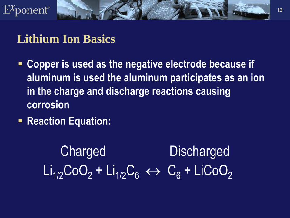
Lithium Ion Basics
Copper is used as the negative electrode because if
aluminum is used the aluminum participates as an ion
in the charge and discharge reactions causing
corrosion
Reaction Equation:
Charged Discharged
Li1/2CoO2 + Li1/2C6 C6 + LiCoO2

13
Types of Lithium Ion Batteries
Cylindrical cells use nickel-plated steel cans
The cell can is at the cell negative potential
Prismatic cells typically use aluminum cans
The cell can is at the cell positive potential
Some larger, heavier prismatic cells use nickel-plated steel cans (can at cell negative potential)
Polymer cells use a polymer coated aluminum foil pouch
Pouch is left electrically floating and is insulated from both the positive and negative terminals of the cell
More sensitive to mechanical abuse
14
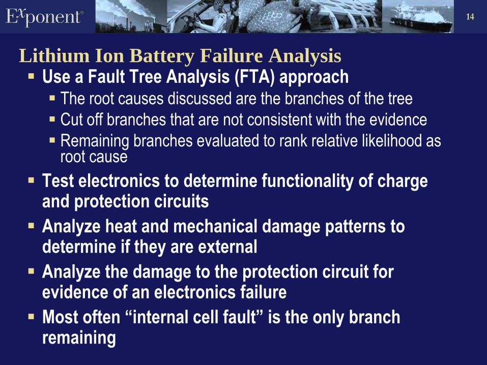
Lithium Ion Battery Failure Analysis Use a Fault Tree Analysis (FTA) approach
The root causes discussed are the branches of the tree
Cut off branches that are not consistent with the evidence
Remaining branches evaluated to rank relative likelihood as root cause
Test electronics to determine functionality of charge and protection circuits
Analyze heat and mechanical damage patterns to determine if they are external
Analyze the damage to the protection circuit for evidence of an electronics failure
Most often “internal cell fault” is the only branch remaining

15
Manufacturing Issues
Microparticle contamination in the active material slurries
used to coat the electrodes
Assembly line tools wear and can drop particles into the
cell raw materials
Cutter blades dull leaving burrs and tears on the current
collector metals and leads connected to the foils
Rough lead to foil connection techniques can leave sharp
edges
Nickel plating on substandard cell cans and other
construction materials can flake and drop into the
“jellyroll” during cell construction

16
Take Control While You Can
The Cells Forget the spec sheet – test to device requirements Confirm quality and continue to check Shop for a deal…but don’t get burned
The Pack, Host Device and Accessories
Don’t stop with the standards and guidelines – understand the possible failure modes and design away from them
Simple, robust circuits based on accepted designs Redundancy for critical operations Respect for the limits of the cells Mechanical integrity sufficient for the intended use and
foreseeable environmental conditions
17
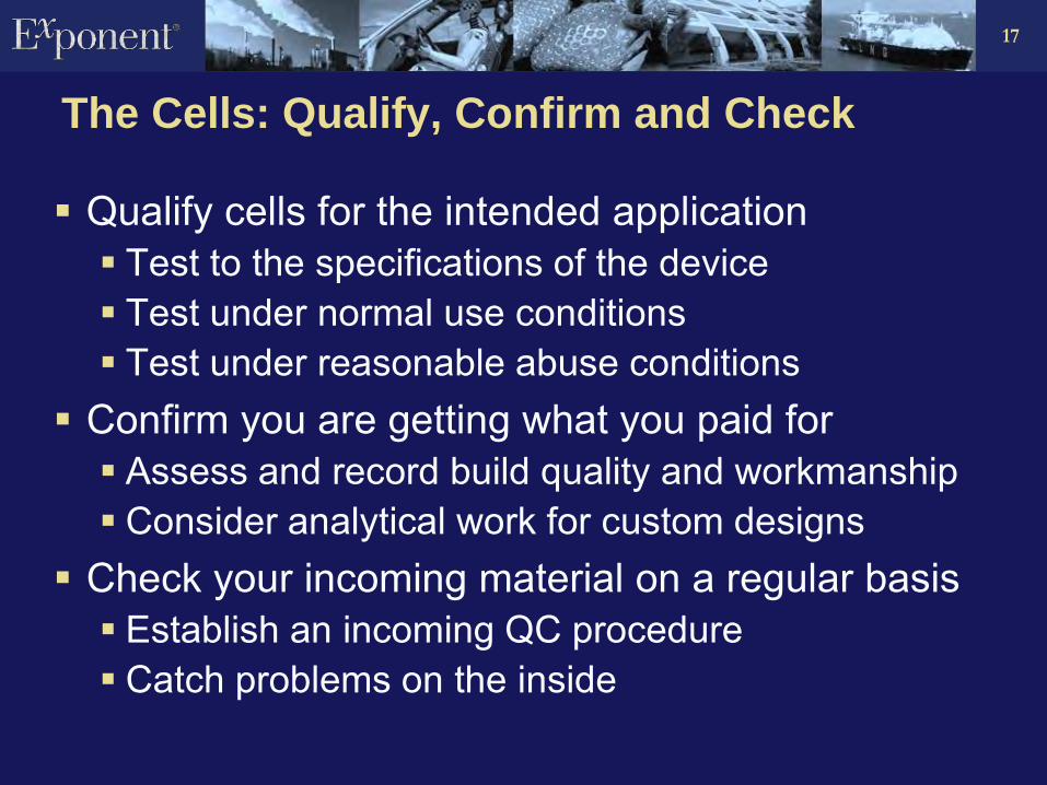
The Cells: Qualify, Confirm and Check
Qualify cells for the intended application Test to the specifications of the device Test under normal use conditions Test under reasonable abuse conditions
Confirm you are getting what you paid for Assess and record build quality and workmanship Consider analytical work for custom designs
Check your incoming material on a regular basis Establish an incoming QC procedure Catch problems on the inside
18
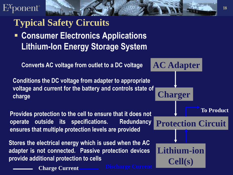
Typical Safety Circuits
Consumer Electronics Applications
Lithium-Ion Energy Storage System
AC Adapter
Charger
Protection Circuit
Lithium-ion
Cell(s)
To Product
Charge Current Discharge Current
Converts AC voltage from outlet to a DC voltage
Conditions the DC voltage from adapter to appropriate
voltage and current for the battery and controls state of
charge
Provides protection to the cell to ensure that it does not
operate outside its specifications. Redundancy
ensures that multiple protection levels are provided
Stores the electrical energy which is used when the AC
adapter is not connected. Passive protection devices
provide additional protection to cells

19
Overcharge Protection
Multiple Cell Application: 4 Independent Levels
1. Charger Output Voltage
2. Battery Protective Switch
3. Electronically Controlled Fuse
4. 18650 Cell Current Interrupt Device (CID)
Prismatic and Polymer Designs Use Thermal Cutoffs (TCO)
Single Cell Application: 2 Independent Levels
1. Charger Output Voltage
2. Battery Protective Switch

20
Overcharge Protection
Battery Protective
Switch
Microcontroller
controlled transistor
switch
In multiple cell
applications each cell
is individually
monitored for
overcharge by the
microcontroller
4.35Vdc 5VdcControl

21
Overcharge Protection
Independent IC:
Secondary Protection
Each cell is
individually monitored
for overcharge
Electronically
controlled fuse is
opened if overcharge
is detected
5Vdc2nd
Protection
4.45Vdc
22
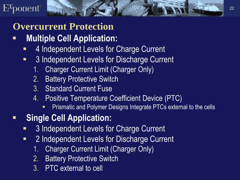
Overcurrent Protection
Multiple Cell Application: 4 Independent Levels for Charge Current
3 Independent Levels for Discharge Current 1. Charger Current Limit (Charger Only)
2. Battery Protective Switch
3. Standard Current Fuse
4. Positive Temperature Coefficient Device (PTC) Prismatic and Polymer Designs Integrate PTCs external to the cells
Single Cell Application: 3 Independent Levels for Charge Current
2 Independent Levels for Discharge Current 1. Charger Current Limit (Charger Only)
2. Battery Protective Switch
3. PTC external to cell
23
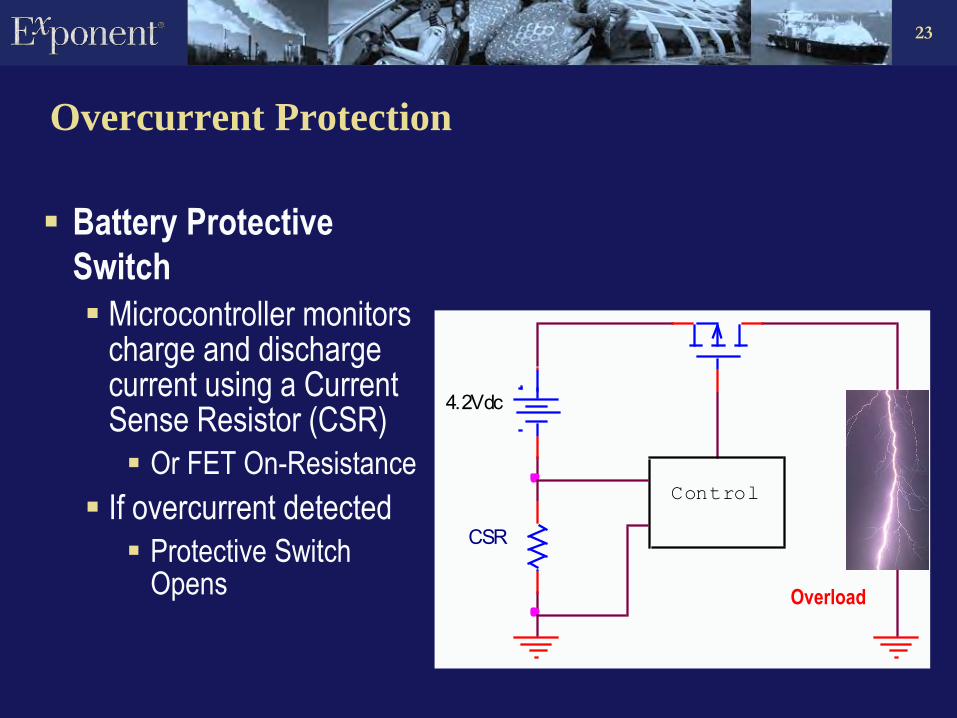
Overcurrent Protection
Battery Protective
Switch
Microcontroller monitors charge and discharge current using a Current Sense Resistor (CSR)
Or FET On-Resistance
If overcurrent detected
Protective Switch Opens
CSR
Control
4.2Vdc
Overload

24
Overcurrent Protection
Standard Current Fuse
Overcurrent will cause the fuse to open
4.2Vdc
Overload
Fuse

25
Imbalance Protection
Series connected cells require imbalance protection
Microcontroller monitors individual cell voltages
Methods of protection include:
3.5Vdc Control
4.2Vdc
8.6Vdc
Rebalancing by diverting charge current from higher voltage cells
If imbalance is severe, electronically controlled fuse can be opened
Fuse

26
Overtemperature Protection
Charge initiation allowed within 0C and 50C range
Charge continuation allowed within 0C and 60C range
Discharge allowed within 0C and 70C range
TC
Control
4.2Vdc4.3Vdc
Microcontroller senses cell temperature using a thermocouple (TC) and terminates charge or discharge current using a switch based on the following typical criteria:

27
Overdischarge Protection
Microcontroller monitors cell voltages
Opens switch when the capacity of the battery is drained
Drained battery will be drained further by protection electronic loading
Protection electronics will shut down when the cell voltages drop below 2V
Load
Control
2Vdc
Drained pack can
be reenabled with
low “pre-charge”
current to bring the
cells back into
normal range

28
Large Battery Systems
Cell designs that assist in the distribution of heat
Ceramic separators to improve thermal stability
Positive electrode material with greater thermal
stability
Case designs to improve heat transfer (fins etc.)
Forced convection mechanisms for heat transfer
Soft packages for cells to provide larger aspect ratios
to aid in better heat transfer
29
Large Battery Systems
Electrical Shock Hazard
HEV Li-ion battery systems have substantially higher operating voltages
Typically 160 V or higher
UL defines a voltage in excess of 42.4 Vac or 60 Vdc as hazardous
Arcing
An arcing fault can result in extremely high temperatures on the order of 10,000°C or higher.
These high temperatures can generate hot gases and molten metal which can result in serious burns and cause clothing to ignite
30
Test standards Lithium-Ion Abuse Standards
Underwriters Laboratories
UL 1642: Lithium Batteries
UL 1973 (Proposed): Batteries for use in Light Electric Rail (LER) Applications and Stationary Applications
UL 2054: Household and Commercial Batteries
UL 2271: Batteries for use in light electric vehicle applications
UL 2580: Batteries for use in electric vehicles
Institute of Electrical and Electronics Engineers (IEEE)
IEEE 1625: Rechargeable Batteries for Multi-Cell Mobile Computing Devices
IEEE 1725: Rechargeable Batteries for Cellular Telephones
American National Standard (ANSI)
C18.2M Part2: Portable Rechargeable Cells and Batteries – Safety Standard
Society of Automotive Engineers (SAE)
J2464: Electric and Hybrid Electric Vehicle Rechargeable Energy Storage Systems (RESS), Safety and Abuse Testing
J2929: Electric and hybrid vehicle propulsion battery system safety standard – lithium based rechargeable cells
31
Lithium-Ion Abuse Standards
International Electrotechnical Commission IEC 62133: Secondary cells and batteries containing alkaline or other non-acid
electrolytes - Safety requirements for portable sealed secondary cells, and for batteries made from them, for use in portable applications
IEC 62281: Safety of Primary and Secondary Lithium cells and batteries during transport
United Nations (UN) Recommendations on the Transport of Dangerous Goods, Manual of Tests and
Criteria, Part III, Section 38.3
Japanese Standards Association JIS C8714: Safety tests for portable Lithium-ion secondary cells and batteries
for use in portable electronic applications
Battery Safety Organization (BSO) Proposed: Manual for the evaluation of energy systems for light electric vehicle
(LEV) – secondary lithium batteries.

32
Battery Systems Support Overview
Failure analysis and root cause determination Litigation
Field Incidents
Recall support
Design evaluation and review
Standard and customized testing abuse/misuse testing
Battery Accelerated aging and predictive life modeling
System integration support
Vehicle Electrical System Battery Pack Electrochemical Cells

33
Multidisciplinary Approach
By forming a multidisciplinary team we have experience with: • Cells
• Power management
• Electrical system
• Risk analysis
• Auditing of component factories
Electrical and Electronics
Thermal Sciences
Electrochemistry and Cell Design
Manufacturing and Quality

34
Equipment and Capabilities: Phoenix
Pack, System and Vehicle Level Support: circuit design and layout
protection and redundancy in the design
choice of components
effects of high voltage
environmental impact on performance (water, temperature, humidity, etc...)
connectivity
characterization and testing of the worst case scenarios
Equipment and Facilities:
Environmental chambers (-25 C to 100 C)
Shock table
Vibration table
Thermal imaging camera
Vacuum chambers
High speed video capability (up to 2000 frames/second)
Maccor cell cyclers
Complete vehicle testing center