live tank circuit breakers buyer’s guide - section …...live tank circuit breakers — buyer’s...
TRANSCRIPT
Live Tank Circuit Breakers Buyer’s Guide - Section Explanations
2 Product information | Live Tank Circuit Breakers — Buyer’s Guide
Table of contents
Page
Introduction 3
Explanations 8
Puffer, Auto-Puffer™ 22
Others:
Quality control and testing 26
Inquiry data 28

Live Tank Circuit Breakers — Buyer’s Guide | Product information 3
ABB is the supplier of cutting edge technology
Our task is to help our customers to a more reliable power grid and sustainable society at large. This is why we always strive for the leading position in research and development. ABB has all the experience necessary for successful development of power transmission technology.
This Buyer’s Guide concerns one of our true specialty areas – high voltage circuit breakers – an area in which we are con-stantly striving to improve product performance that delivers real customer value. What has pushed development forward has been the capability to increase availability at our custom-ers’ installations by supplying reliable high voltage equipment.
Development is a team effortOur development team consists of highly qualified and expe-rienced technicians with expert knowledge in, for example, plasma physics, materials physics, gas dynamics, mechanics and high voltage technology. We also collaborate with others with expert knowledge and skills, both at ABB and externally.
An important aspect of development work is our close dialog with customers, which enables us to find out about their ex-periences. Customers who demand more of our products give us the best platforms to realize new innovations.
Thought leadershipOur design work with constant improvements and simplifica-tion of our products have resulted in; 550 kV circuit breakers without grading capacitors; the Motor Drive with a servo mo-tor system that accurately controls and monitors the contact operation and the LTB D1 and E1 circuit breakers with MSD operating mechanism that provide fast and simple installation at site. Other mile stones:
− 80 kA with only two breaking chambers per pole − The DCB concept that enables smarter, safer and greener
substations − Excellent earthquake performance suitable for seismic
regions − The eco-efficient CO2 circuit breaker LTA
New technology requires careful testing.ABB’s high power laboratory is among the world’s most modern and best equipped labs for switchgear technology, with facilities for testing circuit breakers with rated voltages of up to 1200 kV and breaking currents of up to 80 kA.

4 Product information | Live Tank Circuit Breakers — Buyer’s Guide
Product portfolio Live Tank Circuit Breakers
LTB D1 72.5 – 170 LTB E1 72.5 – 245 LTB E2 362 – 550 LTB E4 800
Standards IEC, IEEE IEC, IEEE IEC, IEEE IEC, IEEE
Rated voltage 72.5 – 170 kV 72.5 – 245 kV 362 – 550 kV 800 kV
Rated current up to 3150 A up to 4000 A up to 4000 A up to 4000 A
Circuit-breaking capacity up to 40 kA up to 50 kA up to 50 kA up to 50 kA
Ambient temperature -30 – +40 ºC -30 – +40 ºC -30 – +40 ºC -30 – +40 ºC
The circuit breakers can also be supplied for ambient temperatures down to -60 or up to +70 ºC.
ABB has a complete portfolio and well proven technology for high voltage circuit breakers used in a number of applications.
HPL 72.5 – 300 HPL 362 – 550 HPL 800
Standards IEC, IEEE IEC, IEEE IEC, IEEE
Rated voltage 72.5 – 300 kV 362 – 550 kV 800 kV *)
Rated current up to 4000 A up to 4000 A up to 4000 A
Circuit-breaking capacity up to 80 kA up to 80 kA up to 80 kA
Ambient temperature -30 – +40 ºC -30 – +40 ºC -30 – +40 ºC
*) Up to 1200 kV on requestThe circuit breakers can also be supplied for ambient temperatures down to -60 or up to +70 ºC.
ON
ONON

Live Tank Circuit Breakers — Buyer’s Guide | Product information 5
Product portfolio Disconnecting Circuit Breakers
As a complement to the basic versions of our circuit breakers, which are primarily designed for conventional substation solutions, there is a disconnecting circuit breaker configuration with the disconnecting function integrated into the breaking chamber. A safe interlocking system, composite insulators and a motor-driven grounding switch provide personal safety.
DCB LTB 72.5 DCB LTB 145 DCB HPL 170-300 DCB 362-550
Standards IEC IEC IEC IEC
Rated voltage 72.5 kV 145 kV 170 - 300 kV 362 - 550 kV
Rated current up to 3150 A up to 3150 A up to 4000 A up to 4000 A
Circuit-breaking capacity up to 40 kA up to 40 kA up to 50 kA up to 63 kA
Ambient temperature -30 – +40 ºC -30 – +40 ºC -30 – +40 ºC -30 – +40 ºC
The disconnecting circuit breakers can also be supplied for other data on request. For more information about DCBs, please see Application Guide 1HSM 9543 23-03en
6 Product information | Live Tank Circuit Breakers — Buyer’s Guide
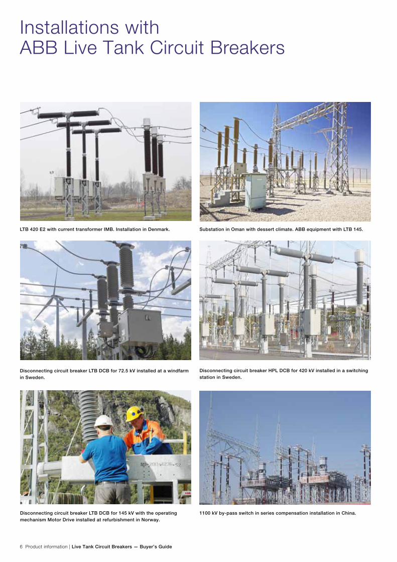
Installations with ABB Live Tank Circuit Breakers
Disconnecting circuit breaker LTB DCB for 72.5 kV installed at a windfarm in Sweden.
Disconnecting circuit breaker LTB DCB for 145 kV with the operating mechanism Motor Drive installed at refurbishment in Norway.
1100 kV by-pass switch in series compensation installation in China.
LTB 420 E2 with current transformer IMB. Installation in Denmark. Substation in Oman with dessert climate. ABB equipment with LTB 145.
Disconnecting circuit breaker HPL DCB for 420 kV installed in a switching station in Sweden.

Live Tank Circuit Breakers — Buyer’s Guide | Product information 7
Exceeding Customer Expectations — ABB Live Tank Circuit Breakers
ABB has over a century of experience in developing, testing and manufacturing high voltage circuit breakers. Through the years, our circuit breakers have acquired a reputation for high reliability and long life in all climates and in all parts of the world.
Our apparatus are manufactured in a workshop where we continuously are working with improvements regarding quality, work environment, environment and safety.
Product range Type Maximum rated
voltage
Maximum rated
current
Maximum rated
breaking current
(kV) (A) (kA)
Circuit Breaker LTB
SF6 Auto-Puffer™ interrupter design
Spring or Motor Drive operating
mechanism(s)
LTB D1/B 170 3150 40
LTB E1 245 4000 50
LTB E2 550 4000 50
LTB E4 800 4000 50
Circuit Breaker HPL
SF6 puffer interrupter design
Spring operating mechanism(s)
HPL B1 300 5000 80
HPL B2 550 5000 80
HPL B4 800 *) 4000 80
Controlled Switching Switchsync™
Condition Monitoring OLM2
*) Up to 1200 kV on request
Other data and/or special applications not covered in this Buyer’s Guide will be quoted on request.
How to interpret the type designationsThe circuit breaker type designations are for simplicity rea-sons not always given in full in this document. The product portfolio basically consists of three product groups:
− LTB xxxD1/B (a single-unit circuit breaker) − LTB xxxEy (a single-, two- or four-unit circuit breaker) − HPL xxxBy (a single-, two- or four-unit circuit breaker)
Circuit breakers of type LTB are SF6 gas circuit breaker of self-blast design while circuits-breakers of type HPL are SF6 puffer circuit breakers. In the full type designation xxx indicates the rated voltage and y indicates number of series connected breaking units per pole. In this document where the circuit breakers are described in general the voltage designations as well as the number of series connected breaking units are omitted.
Other informations For information about Compact air insulated HV switchgear solutions with Disconnecting Circuit Breaker, please see sepa-rate Application Guide. Catalogue publication 1HSM 9543 23-03 en.
Further information about controlled switching applications and Switchsync™ controllers is found in Controlled Switching, Buyer’s Guide/Application Guide. Catalogue publication 1HSM 9543 22-01en.
Information about the new CO2 insulated high voltage circuit breaker LTA is found in brochure 1HSM 9543 21-06en
8 Product information | Live Tank Circuit Breakers — Buyer’s Guide
Explanations
Technical specifications - GeneralStandard/Customer specificationThere are international and national standards, as well as cus-tomer specifications. ABB High Voltage Products can meet most requirements, as long as we are aware of them. When in doubt, please enclose a copy of your specifications with the inquiry.
TestsType tests (design tests) and routine tests (production tests) are required by standards.
- Type tests Type tests are performed only once on one representative test object in accordance with applicable standards and are not repeated without extra charge. The purpose of the type tests is to verify the ratings of the design.
- Routine tests Before delivery routine tests are performed in accordance with applicable standards on each circuit breaker. The purpose of the routine tests is to verify the assembly and the function on every individual circuit breaker. Routine test certificates are sent to the user with each delivery.
Extended routine tests exceeding requirements by standards will be charged extra. Please see special chapter Quality Control and Testing.
Rated voltageThe rated voltage is the maximum voltage (phase-phase), expressed in kV rms, of the system for which the equipment is intended. It is also known as maximum system voltage.
Rated insulation levelThe combination of voltage values which characterizes the insulation of a circuit breaker with regard to its capability to withstand dielectric stresses.
The rated value given is valid for altitudes ≤1000 m above sea level. A correction factor is introduced for higher altitudes.
The definition “Across isolating distance” is only applicable for disconnectors and disconnecting circuit breakers.
Rated LIWL The lightning impulse test is performed with a standardized wave shape 1.2/50 µs for simulation of lightning over-voltage.
The rated Lightning Impulse Withstand Level (LIWL) indicates the required withstand level phase-to-earth (phase-to-ground), between phases and across open contacts. The value is expressed in kV as a peak value.
For voltages ≥300 kV two values are stated by IEC, a LIWL voltage on one of the main terminals and power frequency voltage on the other.
Example 420 kV: 1425 (+240) kV.
Alternatively a LIWL pulse with the sum of the two voltages (1665 kV) can be applied on one terminal, while the other is grounded.
BIL (Basic Insulating Level) is an old expression but means the same as LIWL.
Rated Full Wave is often used in older ANSI/IEEE standards but means the same as LIWL.
Rated Power Frequency Withstand VoltageThis test is to show that the apparatus can withstand the power frequency over-voltages that can occur.
The Rated Power Frequency Withstand voltage indicates the required withstand voltage phase-to-earth (phase-to-ground), between phases and across open contacts. The value is expressed in kV rms.
Rated SIWLFor voltages ≥300 kV the power-frequency voltage test is partly replaced by the switching impulse test. The wave shape 250/2500 µs simulates switching over-voltage.
The rated Switching Impulse Withstand Level (SIWL) indicates the required withstand level phase-to-earth (phase-to-ground), between phases and across open contacts. The value is expressed in kV as a peak value. The switching impulse is required only for voltages ≥300 kV. Two values are stated by IEC, a SIWL voltage on one of the main terminals and power frequency voltage on the other.
Example 420 kV: 900 (+345) kV.
Alternatively a SIWL pulse with the sum of the two voltages (1245 kV) can be applied on one terminal, while the other is grounded.
Live Tank Circuit Breakers — Buyer’s Guide | Product information 9
Rated Chopped Wave Impulse Withstand voltage Phase-to-earth and Across open gapThe rated chopped wave impulse withstand level at 2 µs and 3 µs respectively, indicates the required withstand level phase-to-earth (phase-to-ground) and across open contacts.
The chopped wave impulse is only referred to in IEEE stan-dards and hence, not applicable for IEC.
Rated frequencyThe rated (power) frequency is the nominal frequency of the system expressed in Hz, which the circuit breaker is designed to operate in.
Standard frequencies are 50 Hz and 60 Hz.
Other frequencies, such as 16 2/3 Hz and 25 Hz might be applicable for some railway applications.
Rated normal currentThe rated normal current (sometimes referred to as rated cur-rent, nominal current or rated continuous current) is the maxi-mum continuous current the equipment is allowed to carry. The current is expressed in A rms.
The rated normal current is based on a maximum ambient tempera-ture of +40 °C. At higher temperatures derating of the normal current might be necessary.
Rated short-time withstand currentThe rated short-time withstand current is the maximum cur-rent (expressed in kA rms) which the equipment shall be able to carry in closed position for a specified time duration. The rated short-time withstand current is equal to the rated short-circuit breaking current.
Standard values for duration are 1 or 3 s.
Rated peak withstand currentThe peak withstand current is the peak value of the first major loop (expressed in kA) during a short-time withstand current that the equipment shall be able to carry. The peak value is related to the rms value, frequency and time constant (τ). Specified values are:
- 2.5 x rated short-time withstand current at 50 Hz at τ = 45 ms - 2.6 x rated short-time withstand current at 60 Hz at τ = 45 ms - 2.7 x rated short-time withstand current at 50/60 Hz at τ > 45 ms
Rated short-circuit breaking currentThe rated short-circuit (breaking) current is the maximum symmetrical short-circuit current in kA rms, which a circuit breaker shall be capable of breaking.
Two values are related to the rated short-circuit current:
− The rms value of the AC component − The percentage DC component (depending on the mini-
mum opening time of the circuit breaker and the time constant τ)
Rated short-circuit making currentThe rated short-circuit making current is the maximum peak current the circuit breaker shall be able to close and latch against. This is also referred to in IEEE as closing and latching capability.
Rated short-circuit making current is equal to Rated peak withstand current.
The peak value is related to the rms value of the rated short-circuit breaking current, frequency and time constant (τ). Specified values are:
- 2.5 x rated short-time withstand current at 50 Hz at τ = 45 ms - 2.6 x rated short-time withstand current at 60 Hz at τ = 45 ms - 2.7 x rated short-time withstand current at 50/60 Hz at τ > 45 ms

10 Product information | Live Tank Circuit Breakers — Buyer’s Guide
Explanations
System and Switching Conditions Earthing of the networkThe earthing of the network may vary with region and rated voltage.
For higher rated voltages, networks tend to have effectively earthed neutral. For lower rated voltages, networks usually have non-effectively earthed neutral (isolated or resonant earthed).
The type of earthing is an important parameter for defining the tran-sient recovery voltage
First-pole-to-clear-factorThe first-pole-to-clear-factor (kpp) is depending on the earthing of the network. The first-pole-to-clear-factor is used for calcu-lating the transient recovery voltage for three-phase faults.
In general the following cases apply:
− kpp = 1.3 corresponds to three-phase faults in systems with an effectively earthed neutral.
− kpp = 1.5 corresponds to three-phase faults in isolated systems or resonant earthed systems.
− kpp = 1.0 corresponds to special cases, e.g. two-phase railway systems, short-line fault.
A special case is when there is a three-phase fault without involving earth. This case corresponds to kpp = 1.5. This case is covered by the IEEE standards.
Rated Transient Recovery VoltageThe rated transient recovery voltage (TRV) is the peak tran-sient voltage (expressed in kV) that corresponds to the first-pole-to-clear when interrupting a three-phase fault at rated short-circuit current.
The rated transient recovery voltage (uc) is calculated as fol-lows (based on IEC):
Where:
Ur Rated voltage (kV)
kpp first-pole-to-clear-factor
kaf Amplitude factor (According to IEC: 1.4 at 100% short-circuit current)
Example: At 145 kV with kpp = 1.5 the rated transient recovery voltage will be 249 kV
Rated out-of-phase making and breaking currentThe rated out-of-phase breaking current is the maximum out-of-phase breaking current the circuit breaker shall be capable of breaking.
The standard value of the rated out-of-phase breaking current is 25% of the rated short-circuit breaking current.
Out-of-phaseThe power frequency recovery voltage (rms) for out-of-phase conditions can be calculated as:
The corresponding transient recovery voltage (uc) can be calculated as:
Where:
Ur Rated voltage (kV)
kpp first-pole-to-clear-factor (out-of-phase) or out-of-phase voltage factor
kaf Amplitude factor (According to IEC: 1.25)
Standardized values for the out-of-phase voltage factors are:
− 2.0 for systems with effectively earthed neutral − 2.5 for systems with non-effectively earthed neutral
Example: At 245 kV with kpp = 2.0, the out-of-phase transient recovery voltage will be 500 kV
The applied voltage before making is not affected by the earth-ing of the system. The maximum applied voltage during out-of-phase conditions is always 2.0 times the single-phase voltage.
Rated surge impedance and other short-line fault characteristicsWhen a short-circuit occurs on an overhead line not far from a circuit breaker, traveling waves will generate a very steep first part of the transient recovery voltage. The Rate of Rise of Recovery Voltage, RRRV is depending on the short-circuit current and the surge impedance.
The surge impedance may vary depending on e.g. type of conductors.
In standards IEC and IEEE, the surge impedance has been standardized to a value of 450 Ω.

Live Tank Circuit Breakers — Buyer’s Guide | Product information 11
Other characteristics for the short-line fault are the peak fac-tor and the RRRV factor. These have been standardized to the following values:
Peak factor: 1.6 RRRV factor: 0.2 (kV/µs)/kA for 50 Hz 0.24 (kV/µs)/kA for 60 Hz
Capacitive voltage factorThe capacitive voltage factor is used for defining the single-phase recovery voltage for different capacitive switching ap-plications. The factor is depending on the following:
Application − No-load line switching − No-load cable switching − Capacitor bank switching
Earthing of the network − Earthed neutral − Non-effectively earthed neutral (isolated or resonant earthed)
Standard values for capacitive voltage factors for normal ser-vice conditions are as follows:
No-load line switching: − 1.2 (effectively earthed neutral) − 1.4 (non-effectively earthed neutral)
No-load cable switching: − 1.0 (screened cables in systems with solidly earthed neutral) − 1.2 (belted cables in systems with effectively earthed neutral) − 1.4 (in systems with non-effectively earthed neutral)
Capacitor bank switching: − 1.0 (capacitor bank with earthed neutral in systems with
solidly earthed neutral) − 1.4 (capacitor bank with non-effectively earthed neutral)
When different capacitive voltage factors apply from different applications, the highest value should be referred to.
The voltage factor can be used to calculate the single-phase recovery voltage peak:
Where:
Ur Rated voltage
kc Capacitive voltage factor
Example: What is the peak recovery voltage for a 245 kV breaker when switching a no-load line with earthed neutral?
The voltage factor is 1.2 due to earthed neutral system.
The peak recovery voltage is:
Capacitive switching classThere are two different capacitive switching classes:
− Class C1: Circuit breaker with low probability of restrike during capacitive switching.
− Class C2: Circuit breaker with very low probability of re-strike during capacitive switching.
A circuit breaker intended for Class C2 can of course also be used for Class C1.
Rated capacitive inrush current and inrush frequencyThe rated capacitive inrush current (peak value) is only ap-plicable for circuit breakers intended for switching of (mainly back-to-back) capacitor banks.
The inrush current is characterized by a very high inrush cur-rent and inrush frequency.
Values may vary due to different configurations of capacitor banks, current limiting inductance etc.
Standardized value of inrush current is 20 kA (peak value) and with an inrush current frequency of 4.25 kHz.
Time constantThe time constant of the system is equal to the ratio between inductance and resistance in the network (L/R) and is ex-pressed in ms. Standard value is 45 ms. The time constant will affect the required DC component.
There is a relationship between the time constant and the X/R-ratio. If a required X/R-ratio has been given, the time constant in ms can easily be calculated by dividing the X/R-ratio with (2 x π x f), where f is the rated frequency.
Example: X/R = 14 corresponds to a time constant of 45 ms at 50 Hz X/R = 17 corresponds to a time constant of 45 ms at 60 Hz
12 Product information | Live Tank Circuit Breakers — Buyer’s Guide
Explanations
Ambient Conditions Minimum ambient temperatureThe minimum ambient (air) temperature specifies the lowest temperature at which the circuit breaker shall be able to oper-ate, at specified ratings.
Important standard values are -30 °C and -40 °C
The minimum ambient temperature affects the choice of gas pressure and/or gas mixture.
Maximum ambient temperatureThe maximum ambient (air) temperature specifies the highest temperature at which the circuit breaker shall be able to oper-ate, at specified ratings.
The maximum ambient temperature can affect the continuous current carrying capability.
Standard value is +40 °C.
AltitudeThe external dielectric strength becomes reduced at higher al-titudes due to the lower density of air. Standard dielectric type tests are valid for installations up to 1000 masl. For verifica-tion of the suitability of installation at higher altitudes the test voltages has to be corrected. Correction factor according to standard has to be used for external insulation. (IEC 62271-1)
Creepage distanceThe creepage distance is defined as the shortest distance along the surface of an insulator between two conductive parts.
The required creepage distance is specified by the user in:
− mm (total creepage distance) − mm/kV (creepage distance in relation to the phase to
ground voltage).
NOTE! Creepage distance voltage used to be phase to phase voltage. To avoid confusion check which voltage reference that is used.
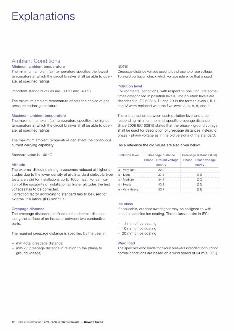
Pollution levelEnvironmental conditions, with respect to pollution, are some-times categorized in pollution levels. The pollution levels are described in IEC 60815. During 2008 the former levels I, II, III and IV were replaced with the five levels a, b, c, d, and e.
There is a relation between each pollution level and a cor-responding minimum nominal specific creepage distance. Since 2008 IEC 60815 states that the phase - ground voltage shall be used for description of creepage distances instead of phase - phase voltage as in the old versions of the standard.
As a reference the old values are also given below.
Pollution level Creepage distance
Phase - Ground voltage
Creepage distance (Old)
Phase - Phase voltage
mm/kV mm/kV
a - Very light 22.0 -
b - Light 27.8 (16)
c - Medium 34.7 (20)
d - Heavy 43.3 (25)
e - Very Heavy 53.7 (31)
Ice classIf applicable, outdoor switchgear may be assigned to with-stand a specified ice coating. Three classes exist in IEC:
− 1 mm of ice coating − 10 mm of ice coating − 20 mm of ice coating
Wind loadThe specified wind loads for circuit breakers intended for outdoor normal conditions are based on a wind speed of 34 m/s, (IEC).
Live Tank Circuit Breakers — Buyer’s Guide | Product information 13
DesignSingle- or three-pole operationFor single-pole operation (1-pole operation), each individual pole of the circuit breaker is operated by its own operating mechanism. This makes single-phase as well as three-phase auto-reclosing possible.
For three-pole operation, (ganged operation) all three poles are operated by a common operating mechanism. The three poles are mechanically linked together for three-phase auto-reclosing.
(Two-pole operation applies only for special applications, i.e. railway systems.)
Trip-free circuit breakerA circuit breaker which can perform a complete opening op-eration, even if the trip command is activated during a closing operation and with the closing command maintained.
NOTE! To ensure proper breaking of the current that may be established, it may be necessary that the contacts momen-tarily reach the closed position.
Fixed tripA circuit breaker that cannot be released except when it is in the closed position.
Pre-Insertion Resistors (PIR)Pre-insertion resistors (closing resistors) are used to limit over-voltages in the network during switching operations. The pre-insertion resistors are only used during closing and consist of resistor blocks that are connected in parallel with the breaking chamber.
The resistor blocks will close the circuit approximately 8-12 ms before the arcing contacts.
Pre-insertion resistors are mainly used at higher system volt-ages (≥362 kV).
For several applications, controlled switching using Switch-sync™ is preferred.
Pre-insertion resistors should not be mixed up with opening resistors, which are used for reducing (damping) the TRV dur-ing opening. Opening resistors are mainly used on older types of circuit breakers, e.g. air-blast circuit breakers.
Rated operating sequenceThe rated operating sequence (also known as standard oper-ating duty or standard duty cycle) is the specified operating sequence, which the circuit breaker shall be able to perform at specified ratings.
There are two main alternatives: a) O - t - CO - t’ - CO
Where:
t 0.3 s for circuit breakers intended for rapid auto-reclosing
t 3 min for circuit breakers not intended for rapid auto-reclosing
t’ 3 min
b) CO - t’’ - CO
Where:
t’’ 15 s for circuit breakers not intended for rapid auto-reclosing
Mechanical endurance classThere are two different mechanical endurance classes:
Class M1: Circuit breaker with normal mechanical endurance (2 000 operations).
Class M2: Frequently operated circuit-breaker for special service requirements (10 000 operations).
A circuit breaker intended for Class M2 can of course also be used for Class M1.
Terminal loadThe conductors connected to the circuit breaker terminals, as well as ice and wind loads, cause the resultant static terminal loads.
Standard values for static terminal loads are given by the standards.
The rated static terminal loads of the equipment are normally verified by load calculations.
14 Product information | Live Tank Circuit Breakers — Buyer’s Guide
Explanations
DesignPressureGas pressures can be expressed in several units, such as MPa, bar, P.s.i etc.
1 MPa = 106 Pa = 10 bar = 145 P.s.i
Rated filling pressureThe rated filling pressure is given at the reference temperature of +20 °C and may be expressed in relative or absolute terms. The rated filling pressure is the pressure to which the circuit breaker is filled before being put into service.
Alarm pressureThe alarm pressure is given at the reference temperature of +20 °C and may be expressed in relative or absolute terms. The alarm pressure is the pressure at which a monitoring (alarm) signal indicates that replenishment is necessary in a relatively short time.
Minimum pressure (Lock out, interlocking or blocking pressure)The minimum pressure is given at the reference temperature of +20 °C and may be expressed in relative or absolute terms. The minimum pressure is the pressure at which the circuit breaker becomes interlocked for further operation and when replenishment is necessary.
All type tests, except mechanical endurance test, are per-formed at this pressure.
Maximum pressureThe maximum pressure is given at the reference temperature of +20 °C and may be expressed in relative or absolute terms. The maximum pressure is the pressure at which the circuit breaker is carrying its normal current at maximum ambient temperature.
Grading capacitorsGrading capacitors are sometimes used on circuit breakers of multi-break design (two or more identical making/breaking units connected in series) to obtain uniform distribution of the voltage stresses across the open gaps. The grading capacitor is connected in parallel with each and every making/breaking unit and has a standard value of 1600 pF/capacitor.
The total capacitance across one open pole is calculated as follows: Ctot = Cgr/n
Where:
Cgr is the capacitance of each grading capacitor.
n is the number of making/breaking units connected in series
Parallel capacitorParallel capacitors are used to modify the line-side transient recovery voltage during short-line fault conditions. Use of a parallel capacitor may result in a higher short-circuit breaking capacity.

Live Tank Circuit Breakers — Buyer’s Guide | Product information 15
Time QuantitiesOpening timeThe opening time is the interval of time from energizing of the opening release (e.g. opening coil) for a circuit breaker being in closed position and the instant when the (arcing) contacts have separated in all poles.
Closing timeThe closing time is the interval of time from energizing of the closing release (e.g. closing coil) for a circuit breaker being in open position and the instant when the (arcing) contacts touch in all poles.
Rated break timeThe rated (maximum) break time (interrupting time) is the time interval between energizing the trip circuit and when the arc is extinguished in all poles. The break time is expressed in ms or cycles (20 ms = 1 cycle at 50 Hz). In IEC, the break-time is based on the results of the terminal fault test duties with symmetrical current. Compensation is made for single-phase testing and for re-duced control voltages.
Dead timeThe dead time (during auto-reclosing) is the interval of time between final arc extinction in all poles in the opening opera-tion and the first re-establishment of current in any pole in the subsequent closing operation. IEC and ANSI/IEEE specify a dead time of 300 ms.
Arcing timeInterval of time between the instant of the first initiation of an arc and the instant of final arc extinction in all poles.
Pre-arcing timeInterval of time between the initiation of current flow in the first pole during a closing operation and the instant when the contacts touch in all poles for three-phase conditions and the instant when the contacts touch in the arcing pole for single-phase conditions.
Reclosing timeThe reclosing time is the interval of time between the energiz-ing of the opening release (e.g. opening coil) and the instant when the contacts touch in all poles during a reclosing cycle. If the differences in operating times (closing and opening time respectively) between poles are small and can be neglected, the following approximative formula can be applied: Reclosing time = Opening time + Arcing time + Dead time + Pre-arcing time
Close-Open timeThe close-open time is the interval of time between the instant of contact touch in the first pole during a closing operation and the instant when the (arcing) contacts have separated in all poles during the following opening operation. The opening release (e.g. opening coil) shall have been ener-gized at the instant when the contacts touch during closing (CO-operation without any intentional time delay; pre-tripped CO-operation). NOTE: The close-open time is not equal to Closing time + Opening time.
Open-Close timeThe open-close time (during auto-reclosing) is the interval of time between the instant of contact separation in all poles and the instant when the contacts touch in the first pole in the subsequent closing operation. If the differences in operating times (closing and opening time respectively) between poles are small and can be neglected, the following approximative formula can be applied: Open-Close time = Arcing time + Dead time + Pre-arcing time
Make timeInterval of time between energizing the closing circuit, the cir-cuit breaker being in the open position, and the instant when the current begins to flow in the first pole.
Make-Break timeThe make-break time is the interval of time between the initia-tion of current flow in the first pole during a closing operation an the end of the arcing time during the subsequent opening operation. The make-break time is based on an operation where the opening release (e.g. opening coil) shall have been energized at the instant when the contacts touch during closing (CO-operation without any intentional time delay also known as a pre-tripped CO-operation). If the differences in operating times (closing and opening time respectively) between poles are small and can be neglected, the following approximative formula can be applied: Make-break time = Pre-arcing time + Close-open time + Arcing time

16 Product information | Live Tank Circuit Breakers — Buyer’s Guide
Explanations
Time definitions according to IEC

Live Tank Circuit Breakers — Buyer’s Guide | Product information 17
Operation and Control Operating Mechanism - Control Cubicle
Control voltageControl voltage is a DC supply used for the control circuits such as: Close circuit and trip circuits etc.
Common rated control voltages: 110, 125, 220 or 240 V DC (Less common rated control voltages: 250, 60 or 48 V DC)
The operating mechanism, including the control circuit, is de-signed for a rated control voltage but must additionally have operational capability throughout a specific voltage range to accommodate variations in supply voltage. The following required voltage ranges are required according to IEC:
Minimum voltage (auxiliary equipment): 85% of rated voltage Maximum voltage (auxiliary equipment): 110% of rated voltage
Minimum voltage (close circuit): 85% of rated voltage Maximum voltage (close circuit): 110% of rated voltage
Minimum voltage (trip circuit): 70% of rated voltage Maximum voltage (trip circuit): 110% of rated voltage
Heating voltage / AC Auxiliary voltageAC Auxiliary voltage is an AC single-phase (phase – neutral) sup-ply used for Heaters, Socket outlet and Lighting etc. when used. Normal values: 110 - 127 V AC 220 - 254 V AC
Motor voltageMotor voltage is a DC supply or an AC single-phase (phase – neutral) supply for the spring charging motor.
Common rated motor voltages: 110, 125, 220 and 240 V DC 115, 120, 127, 230 and 240 V AC
The motor and the motor circuit are designed for a rated voltage but must additionally have operational capability throughout a specific voltage range to accommodate varia-tions in supply voltage. The following required voltage range is required according to IEC:
Minimum voltage for motor circuit: 85% of rated voltage Maximum voltage for motor circuit: 110% of rated voltage
Closing spring charge motorThe closing spring charging motor charges the closing spring after every closing operation.
Motor contactorMotor contactor is controlled by the limit switch and starts / stops the closing spring charging motor. (N.A. for FSA operating mechanism)
Limit switchThe limit switch is monitoring the closing spring charging status.
For operating mechanism BLK and FSA1 it can be of induc-tive or mechanical type.
For operating mechanism BLG and MSD only mechanical type.
Auxiliary contactsAuxiliary contacts are contacts that show the circuit breaker position.
At least one contact is used in each control circuit (trip / close) to control the coil supply. Contacts not used in control circuits, are normally connected to terminals for customer use.
Normal spare contact quantities for customer use: FSA: 7 NO + 7 NC BLK: 8 NO + 8 NC BLG: 9 NO + 9 NC MSD: 9 NO + 9 NC
NO = Normally open, NC = Normally closed
Impulse contact / Wiping contactA contact that gives an short impulse during contact movement.
Local / Remote / Disconnected selector switchThe local / remote / disconnected selector switch is used to switch between remote operating and local operating (via the open / close switch). It also has a disconnected position where operation is not possible. However a protection trip by-pass can be supplied that makes it possible to trip the circuit breaker remotely even in disconnected position.
As an alternative a Local / Remote switch without disconnect-ing possibility can be provided.

18 Product information | Live Tank Circuit Breakers — Buyer’s Guide
Operation and Control Operating Mechanism - Control Cubicle
NC-contactNC-contact (normally closed contact) is a closed contact when device is not ener-gized or in the drawn situation, according to circuit diagram. Could also be called: Break contact or b-contact.
NO-contactNO-contact (normally open contact) is an open contact in the same situation. Could also be called: Make contact or a-contact.
NOC-contactNOC-contact (normally open-closed con-tact) is a closed contact that opens and an open contact that closes with a common backside when changing position. Could also be called: Change-over contact.
Trip / Close switchThe trip / close switch is used for control operations, when the local / remote (/ disconnected) switch is in local position.
CounterThe counter is a non-resettable electromechanical counter that counts every close operation. (FSA has a mechanical counter)
Anti-pumping relayThe anti-pumping relay is a device that makes sure that there can be only one closing operation for each closing order.
MCB – Miniature Circuit BreakerThe MCB (Miniature Circuit Breaker) is a small automatic breaker that can be manually controlled or automatically tripped due to over-current.
The over-current is either thermal (type K) or peak value (type B). 1NO + 1NC auxiliary contacts, that shows MCB position, can be included.
The MCB is normally used for AC auxiliary circuit (and motor circuit for operating mechanism type BLK)
Direct On Line Motor StarterDirect On Line Motor Starter is a motor protection and manual
control unit. This could also be an MCB (thermal controlled type). This unit trips the motor supply when motor overload occurs or when the Direct On Line Motor Starter is manually operated.
Operating coilsClose and trip coils in operating mechanisms BLK, BLG and MSD have relatively low power consumption, normally 200 W, due to a very good latch design. One close and two trip coils are supplied as standard.
Additional close coils can be supplied as option. Also the second trip coil can be of the double type and additional trip circuit can be used.
Hand / Motor switchThe hand / motor switch disconnects the motor circuit during hand cranking. The hand / motor switch, either manual or automatic, has the following functions:
− Motor position; connects the motor to the power supply. − Hand position; short-circuits the motor and is used as a
generator brake.
(N.A. for FSA and MSD operating mechanism)
Heaters, Thermostat, Humidity controllerEvery operating mechanism has a continuous connected anti-condensation heater of 70 W.
In addition to that, one or more controlled heaters are fitted, depending on ambient temperature or humidity. These are controlled by a thermostat, or as an option, a humidity con-troller (a moisture detector controller).
Density switchThe density switch is a device that measures the ambient temperature compensated gas pressure, inside the circuit breaker. Therefore, alarm signal and blocking function are activated only if the pressure drops due to leakage.
The density switch includes normally: a scale display, one contact indicating the alarm pressure and two contacts con-trolling the gas-supervision interlocking relays at the blocking level.
Explanations

Live Tank Circuit Breakers — Buyer’s Guide | Product information 19
Operation and control - ABB options
Gas supervision- Fail-safeNormally a switch with contacts closing at low gas-pressure is used.
A fail-safe option can be supplied where contacts are opening at low gas-pressure, so the gas supervision interlocking relays are energized until the blocking occurs.
- Trip at low SF6
Another option is trip at low SF6-pressure. This option gives a trip order via the gas- supervision interlocking relays at the same time blocking occurs. Most type tests are carried out at this blocking pressure.
Panel lightPanel light can as an option be fitted on the control panel.
The panel lamp is automatically switched on when the panel door is opened.
Socket outletSocket outlet can be fitted inside the cubicle.
Normal designs are:
− Schucko – Commonly used in Northern Europe − (CEE 7/7) Round 2-pole socket with earth-bars on side. − CEE 7/4 – French/Belgium std. with round 2-pole plug with
inverted earth-pole. − Hubbel – American standard. − Crabtree – British standard. − GPO – Australia
TCS – Trip Circuit SupervisionTCS – Trip Circuit Supervision is mainly used to check the connection between the protection trip relay (control room) and the operating mechanism and secondly the trip coil(s) inside the operating mechanism(s).
The TCS is a device that can be fitted in parallel with the pro-tection trip relay(s) and sends a low (< 50 mA) testing current through the trip circuit(s).
To be able to monitor the trip circuits when the circuit breaker is in open position (when the auxiliary contact in the trip circuit is open), there is a parallel wiring to this contact. There are two normal ways to do this:
1. A resistor in parallel with this contact, with resistance value given by the supplier of the TCS device.
2. A NC-contact of the auxiliary contact in parallel with the original NO-contact. This requires either 2 outputs from the TCS-device or two parallel TCS-devices.
An example of TCS device is SPER from ABB ATCF.
Resistor values for SPER, according to 1. above: 220 V dc. 33 kΩ 110 V dc. 22 kΩ 60 V dc. 5.6 kΩ 48 V dc. 1.2 kΩ
Protective tripThe protective trip in the trip circuits is a direct line, by-pass-ing the Local / Remote selector switch.
Note! Used only when protective tripping should override the selector switch.
Position indicating lampsAs an option we can supply green/red-indicating LED-lamps connected to the auxiliary switch for circuit breaker position indication inside the cubicle.

20 Product information | Live Tank Circuit Breakers — Buyer’s Guide
Explanations
Operation and control - ABB options
Key-interlockProvision for key-interlock is mechanical (and electrical) in-terlocking device, which interlocks the closing function, with a bracket suitable for installing the following brands: Castell, Kirk and Fortress.
Emergency trip, manual trip push-buttonManual mechanical trip push-button can on request be fitted on the inside or the outside of the operating mechanism. (Only inside for FSA) Note! Mechanical trip overrides SF6-blocking
69-deviceAn interlocking device, according to device No. 69 in the ANSI standard, that requires a resetting after each manual tripping before closing of the circuit breaker can be done. (N.A. for FSA operating mechanism)
Spring charge supervisionAs an option a relay can be fitted to give an alarm when one or more of the errors / events below occurs:
1. Loss of motor voltage.
2. The direct on line motor starter is tripped manually.
3. The direct on line motor starter is tripped due to over-current.
4. An electrical error prevents spring charging.
5. A mechanical error prevents spring charging.
The relay can be an auxiliary relay or with a time delay relay depending on alarm delaying possibility in the bay control unit. The alarm delay must be at least as long as the spring charg-ing time, normally 15 s.
Voltage supervisionThe circuits can be equipped with voltage supervision relay(s).
This could be a zero-voltage relay (a standard auxiliary relay -not adjustable) or voltage supervision relays (with adjustable setting for voltage and hysteresis).
Heater supervisionThe heating circuit can be equipped with a current supervision relay (with adjustable setting for current and hysteresis) or an in-dicating lamp in series with the continuously connected heater.
Capacitor trippingTrip circuits can be equipped with capacitor tripping devices. Used to automatically trip the circuit breaker at loss of, or at low operating voltage.
The capacitor tripping device is always used together with a voltage supervision relay (adjustable setting for voltage and hysteresis) that controls the tripping voltage level (one capaci-tor device / trip coil is required).
0-voltage trip coilThe operating mechanisms can be equipped with 0-voltage Trip coil. It is used to automatically trip the circuit breaker at loss of, or low operating voltage.
The 0-voltage Trip coil is always used together with a voltage supervision relay (adjustable setting for voltage and hysteresis) that controls the tripping voltage level.
FusesFuses can be fitted in every circuit on request.
Normal types:
− MCB – Miniature Circuit Breaker − Red spot – Fuses (Links) − UK 10,3-HESI – Fuses (Links)
Note! The trip and close circuits should preferably not include fuses.
Phase discrepancyPhase discrepancy (Pole discordance) is a device that could be used on single pole operated circuit breakers, that uses auxiliary contacts to indicate that all phases are in the same position. When the poles are in different positions a time relay starts, and after a pre-set time, a trip order and alarm signal is normally initiated.

Live Tank Circuit Breakers — Buyer’s Guide | Product information 21
Seismic conditions
Seismic stressThere are many zones in the world where earthquakes may occur, and where circuit breakers should be designed to withstand the corresponding stresses. When an earthquake occurs, the acceleration and amplitude of the motion of the ground will vary in a statistical manner. The stress conditions are normally most severe in the horizontal direction. The type of soil (sand, clay, rock, etc) has a strong influence on the actual local severity of an earthquake and the damage it may inflict.
For technical purposes earthquake stresses are normally de-fined by the maximum value of the horizontal acceleration. IEC has standardized three values of maximum horizontal accel-eration 2, 3, and 5 m/s2, corresponding to 0.2, 0.3, and 0.5 g.
IEEE, which is more relevant (more severe) has corresponding standardized values, 0.25 g and 0.5 g respectively for moderate and heavy seismic action.
Resulting stress on circuit breakersWhen a HV circuit breaker is subjected to an earthquake, the motion of the ground will induce oscillations in the circuit breaker with corresponding mechanical stress. The mechani-cal stress will normally be most severe at the lower end of the support column.
The circuit breaker will have one or more natural oscillation frequencies, eigenfrequencies, where the predominant one is typically a few Hz. Since the frequency of typical earthquake oscillations is also of the order of a few Hz, the actual stress on the breaker may be is amplified due to mechanical reso-nance. The degree of amplification depends on the eigen-frequency (natural oscillation frequency) and damping of the circuit breaker, and may be deduced from response spectra, published e.g. by IEC.
Earthquake dampersAn earthquake damper will increase the damping of the natu-ral oscillation of the circuit breaker. In this way the amplifica-tion of earthquake stresses due to resonance is significantly decreased, and the maximum mechanical stress on the circuit breaker significantly reduced.
Verification of seismic capabilityThe seismic capability of a circuit breaker may be verified by a direct test, where a complete circuit breaker, or pole, is sub-jected to simulated earthquake stress on a shaker table.
Alternatively, the mechanical stresses can be determined by calculations. The most reliable calculations are based on a snap-back test. In this test a force is applied on the top of the circuit breaker pole. When the force is suddenly released the pole will oscillate and the eigenfrequencies and the damping can be measured.
22 Product information | Live Tank Circuit Breakers — Buyer’s Guide
Design features Puffer interrupters
1
2
3
4
5
6
7
8
9
10
11
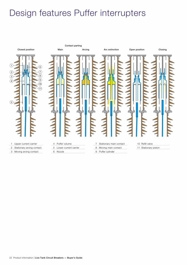
Closed position ClosingOpen positionMain Arcing Arc extinction
Contact parting
1 Upper current carrier
2 Stationary arcing contact
3 Moving arcing contact
4 Puffer volume
5 Lower current carrier
6 Nozzle
7 Stationary main contact
8 Moving main contact
9 Puffer cylinder
10 Refill valve
11 Stationary piston
Live Tank Circuit Breakers — Buyer’s Guide | Product information 23
In its normal position, the circuit breaker contacts are closed and current is conducted from the upper current collector to the lower current collector via the main contacts, the puffer cylinder and the sliding contact system in between the puffer cylinder and the lower current collector.
At opening, the moving parts of the main and arcing contacts, as well as the puffer cylinder and nozzle, are pulled towards the open position. Note that the moving contacts, nozzle and puffer cylinder form one moving assembly.
As the moving assembly is drawn towards the open position, the refill valve is forced to close. The movement of the puffer cylinder versus the stationary piston now starts creating a compression of the SF6 gas inside the puffer cylinder. Due to the contact overlap this gas compression starts before any contacts separate. After some further movement of the moving assembly the main contacts separate which results in a commutation of the current into the arcing contact path, which is still engaged. The much longer contact penetration of the arcing contact system versus the main contact system will ensure that any arc established will be trapped in between the arcing contacts and within the surrounding nozzle.
When the arcing contacts separate after some further contact travel an arc is drawn between the moving and stationary arcing contacts. As the arc flows it will also to some degree block the flow of SF6 gas through the nozzle. Thus the gas pressure in the puffer volume continues to increase.
When the current waveform approaches a current zero, the arc becomes relatively weak and the pressurized SF6 gas in-side the puffer cylinder flows through the nozzle and cools the contact gap which reduces the electrical conductivity such that the arc is extinguished. The low electrical conductivity then prevents the current to continue.
When the current is blocked the recovery voltage starts rising across the contacts. At this time the circuit breaker contacts must have reached a contact distance long enough to create a voltage withstand that all the time exceeds the recovery voltage.
In the fully open contact position there is sufficient distance between the stationary and moving contacts to withstand rated dielectric levels.
On closing, the refill valve opens so that SF6 gas can be drawn into the puffer volume making the circuit breaker ready for the next opening operation.
Note that the SF6 gas pressure required for interruption is built up by mechanical means. Therefore circuit breakers us-ing puffer interrupters require trip mechanisms with sufficient energy to overcome the pressure build up in the puffer volume required to interrupt rated short-circuit current while at the same time maintaining the contact speed required to with-stand recovery voltage.

24 Product information | Live Tank Circuit Breakers — Buyer’s Guide
Design features Auto-Puffer™ interrupters
Closed position ClosingOpen positionMain Arcing Arc extinction
Contact parting
1 Upper current carrier
2 Stationary arcing contact
3 Moving arcing contact
4 Auto-Puffer™ volume
5 Puffer volume
6 Refill valve
7 Stationary piston
8 Nozzle
9 Stationary main contact
10 Moving main contact
11 Auto-Puffer™ valve
12 Puffer cylinder
13 Over-pressure relief valve
14 Lower current carrier
2
1
3
8
9
10
11
12
6
4
5
13
14
7
13
6

Live Tank Circuit Breakers — Buyer’s Guide | Product information 25
High current interruptionWhen interrupting high currents (e.g. rated short-circuit current), Auto-Puffer™ interrupters show the advantage they were designed to provide.
At opening, the operation of an Auto-Puffer™ interrupting a high current begins the same way as for a puffer interrupter. It is not until after the arcing period begins that a difference in the operation principle is seen between the high and low current interrupting modes.
When the arcing contacts separate, an arc is drawn between the moving and stationary arcing contacts. As the arc flows, it to some degree blocks the flow of SF6 gas through the nozzle. Due to the high temperature of the arc it radiates a lot of heat and begins to heat the SF6 gas in the arc quenching zone. Thus, the pressure inside the Auto-Puffer™ and puffer vol-umes increases due to the rise in temperature as well as due to the compression of gas between the puffer cylinder and the stationary piston.
Gas pressure inside the Auto-Puffer™ volume continues to increase and a certain pressure it is high enough to force the Auto-Puffer™ valve to the closed position.
All SF6 gas required for interruption is now trapped in the fixed Auto-Puffer™ volume and any further increase in gas pressure in that volume is due solely to heating from the arc.
At about the same time, the gas pressure in the puffer volume reaches a level high enough to open the overpressure relief valve in the puffer piston. Since the gas in the puffer volume then escapes through the overpressure valve, there is no need for a high operating energy to overcome the compression of SF6 gas while at the same time maintaining the contact speed necessary to create contact distance for withstanding the recovery voltage.
When the current waveform approaches zero, the arc be-comes relatively weak. At this point, the pressurized SF6 gas returns from the Auto-Puffer™ volume and flows through the nozzle and extinguishes the arc.
At closing, the refill valve opens such that gas can be drawn into the puffer and Auto-Puffer™ volumes.
Low current interruption When interrupting low currents, Auto-Puffer™ interrupters act very much in the same way as puffer interrupters. There is not sufficient gas pressure generated by the heat of the arc to force the Auto-Puffer™ valve to close. Therefore the fixed Auto-Puffer™ volume and puffer volume form one large common puffer volume. In such a case, the SF6 gas pressure required for interruption is built up by mechanical means only as in a puffer interrupter.
Unlike a puffer interrupter, however, Auto-Puffers™ need only mechanically generated pressure build-up sufficient to inter-rupt a portion of the rated short-circuit current (i.e. 20% to 30% of the rated short-circuit current).
In the open position, there is sufficient distance between the stationary and moving contacts to withstand rated dielectric levels.
Because interruption of low currents requires only moderate build-up of SF6 gas pressure which is generated by mechani-cal means and since high current interruption uses heating from the arc to generate necessary gas pressure in a fixed volume, Auto-Puffer™ interrupters require far less operating energy than puffer interrupters (i.e. about 50% less).

26 Product information | Live Tank Circuit Breakers — Buyer’s Guide
Quality control and testing
QualityABB High Voltage Products in Ludvika has an advanced quality management system for development, design, manu-facturing, testing, sales and after sales service as well as for environmental standards, and is certified by Bureau Veritas Certification for ISO 9001 and ISO 14001.
Testing resourcesABB has the facilities for carrying out development tests, type tests and routine tests on the circuit breakers. The laborato-ries for testing are located in Ludvika close to the factories and the offices for development, design and planning.
With these testing resources ABB is in the forefront in devel-oping new and safe products for the 21st century.
Type testsThe High Power Laboratory is owned by ABB and has facili-ties for high power tests, temperature rise tests and mechani-cal tests. It is also accredited by SWEDAC (Swedish Board for Technical Accreditation). In the STRI AB laboratory, mainly high voltage tests, environ-mental and special long time duration tests are carried out.
In both laboratories tests in accordance with the requirements stipulated in the international standards IEEE and IEC can be performed. It is also possible to carry out special tests speci-fied by our customers.
The High Power Laboratory as well as STRI has status of independent laboratory and both are members of SATS (Scandinavian Association for Testing of Electric Power Equip-ment), which in turn is a member of STL (Short Circuit Testing Liaison).
STL provides a forum for international collaboration between testing organizations.
Routine testsThe routine tests are part of the process of producing the circuit breakers and are always performed with the same test procedures, irrespective whether or not the tests are witnessed by the client’s representative.
The circuit breaker pole or poles are tested together with the corresponding operating mechanism.
For single-pole operated circuit breakers type HPL B and LTB E, the routine tests are always individually performed for each pole.
Circuit breakers type LTB D and three-pole operated circuit breakers type HPL and LTB E are always routine tested as complete three-phase units.
In general, the routine tests are performed according to IEC or ANSI/IEEE standards.
The main routine tests steps with respect to IEC, IEEE and ABB standards are summarized in the table below.
The entire routine tests for each circuit breaker is documented in a detailed routine test report, generated by the computer-ized testing system. After verification by the ABB certified test supervisor, this report is provided to the customer as part of the order documentation.
DescriptionA summary description of the ABB production and routine tests process is provided in the brochure 1HSM 9543 21-03. A detailed description of the routine tests is given in the docu-ment 1HSB 4154 09-646.
Summary of routine tests
IEC IEEE ABB
Nameplate and design check X X X
Resistance measurement
(Components in auxiliary and control circuits)
X X X
Function check of auxiliary and control circuits X X X
Mechanical operating test X X X
Resistance measurement (Main circuit) X X X
Dielectric test (Auxiliary and control circuit) X X X
Overpressure test N/A X X
Dielectric test (Main circuit) X X X
Tightness test X X X
Live Tank Circuit Breakers — Buyer’s Guide | Product information 27
Processes and support
The circuit breaker organization is process-oriented with focus on deliveries to customers. The process is continuously optimized with respect to time and quality.
Sales and Order handlingIn order to assure that the deliveries fulfill the requirements in the Purchase Order (P.O.) special attention is focused on:
− Assuring the hand over of the P.O. from the Sales to the Order department.
− Order clarification, assuring the particular tasks of order, order design, purchasing and production departments.
− Possible order modifications.
The tools to monitor the orders are continuously improved in order to give our customers the best possible service.
Supply management and PurchasingThe circuit breaker unit has well defined processes for selec-tion and approval of suppliers.
Special attention is addressed to audits at the suppliers plant, the manufacturing, Inspection and Test Plan (ITP) and the On Time Delivery (OTD) monitoring.
The suppliers are evaluated continuously with respect to qual-ity and ODT.
Production and AssemblyAll employees are trained and certified with respect to their responsibilities. Inspections and test plans together with inspection records and control cards have been prepared for all circuit break-ers in order to assure that all activities and the assembly are performed according to the specification.
Service and SparesThe circuit breaker unit takes care of the customer’s require-ments with respect to service and spare parts. Certified trav-eling service engineers are available at the plant in Ludvika. Also, in order to be able to assist our customers as fast as possible, local service centers are established in several parts of the world.
In case of emergencies a 24-hour telephone support is available (ph.: +46 70 3505350). By calling this number customers will get in touch with one of our representatives for immediate consultation and action planning.
Research and DevelopmentThe R&D process is utilizing a project management model with well-defined gates in order to assure that all customer requirements and technical issues are addressed.
28 Product information | Live Tank Circuit Breakers — Buyer’s Guide
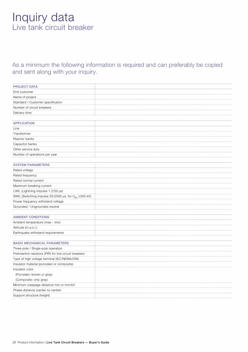
Inquiry dataLive tank circuit breaker
As a minimum the following information is required and can preferably be copied and sent along with your inquiry.
PROJECT DATA
End customer
Name of project
Standard / Customer specification
Number of circuit breakers
Delivery time
APPLICATION
Line
Transformer
Reactor banks
Capacitor banks
Other service duty
Number of operations per year
SYSTEM PARAMETERS
Rated voltage
Rated frequency
Rated normal current
Maximum breaking current
LIWL (Lightning impulse 1.2/50 µs)
SIWL (Switching impulse 25/2500 µs, for Um ≥300 kV)
Power frequency withstand voltage
Grounded / Ungrounded neutral
AMBIENT CONDITIONS
Ambient temperature (max - min)
Altitude (m.a.s.l.)
Earthquake withstand requirements
BASIC MECHANICAL PARAMETERS
Three-pole / Single-pole operation
Preinsertion resistors (PIR) for line circuit breakers
Type of high voltage terminal (IEC/NEMA/DIN)
Insulator material (porcelain or composite)
Insulator color
(Porcelain: brown or gray)
(Composite: only gray)
Minimum creepage distance mm or mm/kV
Phase distance (center-to-center)
Support structure (height)

Live Tank Circuit Breakers — Buyer’s Guide | Product information 29
OPTIONAL MECHANICAL PARAMETERS
Bursting discs
Bracket for CT
Primary connections CB – CT
Manual trip
DATA FOR OPERATING MECHANISM
Control voltage (Coils and relays)
Motor voltage
AC-voltage (heaters, etc.)
Number of free auxiliary contacts
Special requirements
ACCESSORIES
SF6 gas for pressurizing
Gas filling equipment
Controlled Switching (Switchsync™)
Condition monitoring (OLM)
Test equipment
- SA10
- Programma
Tools
Spare parts
NOTE! For information regarding the parameters asked for see chapter “Explanation”.
As a minimum the following information is required and can preferably be copied and sent along with your inquiry.

Contact us
Pub
licat
ion
1HS
M 9
543
22-0
0en,
Edi
tion
6, 2
014-
04, L
ive
Tank
Circ
uit B
reak
ers,
Buy
er’s
Gui
de -
Sec
tion
Exp
lana
tionsABB AB
High Voltage ProductsSE-771 80 LUDVIKA, SWEDENPhone: +46 (0)240 78 20 00 Fax: +46 (0)240 78 36 50 E-mail: [email protected] www.abb.comwww.abb.com/highvoltage
©Copyright 2014 ABB. All rights reserved
NOTE! ABB AB is working continuously to improve the
products. We therefore reserve the right to change designs,
dimensions and data without prior notice.