lll - university of victoria
TRANSCRIPT


lll
Table of Contents
Abstract 11
Table of Contents lll
List of Figures Vl
Glossary of Acronyms viii
Acknowledgments lX
1
1.1 Introduction _________________________ 1
1.2 Crystal Growth Techniques ____________________ 1
1.2.1 Vapor Growth Techniques __________________ _
1.2.2 Growth from Liquid Phase (Melt) ________________ 3
1.2.2. l Bridgman 3
1.2.2.2 Vertical Gradient Freezing (VGF) 4
1.2.2.3 Czochralski (CZ) 5
1.2.2.4 Float Zone (FZ) 6
1.2.3 Solution Growth 7
1.2.3 .1 Traveling Heater Method (THM) 8
1.2.3.2 Liquid Phase Epitaxy (LPE) 10
1.2.3.3 Liquid Phase Electroepitaxy (LPEE) 11
1.3 Solution Concentration _____________________ 13
1.4 Contamination Considerations __________________ 14
1.5 Control of Growth Conditions __________________ 15
1.6 Rotating and Fixed Magnetic Fields in Crystal Growth __________ 16
1.7 Literature Review _______________________ 18

lll
Table of Contents
Abstract 11
Table of Contents lll
List of Figures Vl
Glossary of Acronyms Vlll
Acknowledgments lX
1 BACKGROUND __________________ 1
1.1 Introduction _________________________ 1
1.2 Crystal Growth Techniques ____________________ 1
1.2.1 Vapor Growth Techniques 1
1.2.2 Growth from Liquid Phase (Melt) 3
1.2.2.1 Bridgman 3
1.2.2.2 Vertical Gradient Freezing (VGF) . 4
1.2.2.3 Czochralski (CZ) 5
1.2.2.4 Float Zone (FZ) 6
1.2.3 Solution Growth 7
1.2.3 .1 Traveling Heater Method (THM) 8
1.2.3.2 Liquid Phase Epitaxy (LPE) 10
1.2.3.3 Liquid Phase Electroepitaxy (LPEE) 11
1.3 Solution Concentration _____________________ 13
1.4 Contamination Considerations __________________ 14
1.5 Control of Growth Conditions __________________ 15
1.6 Rotating and Fixed Magnetic Fields in Crystal Growth __________ 16
1.7 Literature Review _______________________ 18

lV
1.8 Cadmium Zinc Telluride (CdZnTe) ________________ 22
1.8. 1 Applications 22
1.8.2 Production 25
1.9 Purpose and Outline _____________________ 26
2 THERMAL ANALYSIS BY THE FINITE ELEMENT METHOD ____ 27
2.1 Introduction ________________________ 27
2.2 Model Development _____________________ 27
2.3 Mesh Generation ______________________ 29
2.4 Models Description ______________________ 31
2.5 Solution __________________________ 33
2.6 Results and Discussions ____________________ 34
3 DESIGN ____________________ 39
3.1 Introduction ________________________ 39
3.2 Linear Translator ______________________ 39
3.3 Furnace __________________________ 43
3.4 Rotating Magnetic Field ____________________ 46
3.5 The Fixed Magnetic Field ___________________ 48
3.6 Power Supply and Control ___________________ 49
3.7 Furnace Stands _______________________ 51
4 OPERATING PROCEDURE _____________ 53
4.1 Introduction ________________________ 53
v
4.2 Furnace Assembly 53
4.3 Furnace Operation 54
4.4 Linear Translator Operation 55
4.5 Rotating Magnetic Field Operation 56
5 CONCLUSION AND FUTURE RECOMMENDATIONS 57
6 BIBLIOGRAPHY 60
APPENDIX A Source Code for Ansys Models __________ 64
APPENDIX B Engineering Drawings ______________ 72

Vl
List of Figures
Figure 1 A typical Vapor Growth Setup ........ ................... .. ... .... ..... ..... .. ......... .. ............... ................ 2
Figure 2 Vertical Brigman Method ...... ..... .............. ..... .................................... ...... ........... ..... .. .... .... 4
Figure 3 A Typical Apparatus Used for Czochalski Growth ........... ........ ........ ... ... ..... .. ..... .............. 6
Figure 4 Apparatus used for Floating Zone Growth .... ..................................................... ..... .. ... ..... 7
Figure 5 TlIM Growth Apparatus .............................................................................. .............. ... .... 8
Figure 6 TlIM Ampoule and Temperature Profile (Meric et. al. 1999) ...................................... .... 9
Figure 7 Simple Diagram of Sliding Boat Horizontal LPE Apparatus ....... ................................. .. 10
Figure 8 A Typical LPEE Crucible Setup ..................................................................................... 12
Figure 9 Concentrations under stable (a) and unstable (b) growth conditions (Hurle 1994) .. ....... 13
Figure 10 Connective Cells in Growth Solution under a) gravity and zero field b) zero gravity and
zero field c) gravity and a RMF (Senchenkov 1998) ............................................................. 1 7
Figure 11 Connective Cells in Growth Solution under a) gravity and zero field b) gravity and a
RMF c) zero gravity and a RMF (Microgravity News 1997, www.larc.nasa.gov) .. .............. 17
Figure 12 Ansys PLANE55 Planer Element.. ..... ....... ....... ..................................... ........... .. .... .... .. . 29
Figure 13 Ansys PLANE77 Planer Element.. ......... ..... ............................................... .. .... ..... ........ 30
Figure 14 Computational Domain of Amistare's Prototype Furnace .......... ................................... 31
Figure 15 Sloping Cooling Block Design .. ....... ...... ... ...... .. .......... .... ..... ....................................... .. 32
Figure 16 Extended Cooling Block Design ........................ .............................................. ..... ...... .. 33
Figure 17 Isothermal Plot of Amistar Furnace Design .................................................................. 34
Figure 18 Isothemals of Sloping Cooling Block. .... .............................. ...... ..... ... ... ..... .. .... ........ ... .. 35
Figure 19 !so thermals of Final Extended Cooling Block .... ....... ..... ........ ........ .............................. 36
Figure 20 Temperature Profile of Amistar and TIIM-l(values taken at model) ....... ... ... .............. 37
Figure 21 Temperature Profiles of Amistar Furnace and TlIM-1 Furnace ................................... 38
Figure 2? Linear Translator .... ..... ..... ........... .. ........ ..... ...... .... ...... .... .... .... ... ..... .............. ........... ... ... 41
Figure 23 Motor and Gearbox ....................................................................................................... 42
Figure 24 Cooling Bl9ck and Components of Furnace Casing ............................. ........................ 44
Figure 25 Exploded View of Ceramic Furnace Parts and Cooling Block .................. ... ... ...... ..... .. 45
Figure 26 Bobbin Location and Dimensions ... ....... ..... ....... ............. ..... .... ... ......................... ..... .. .. 4 7
Figure 27 Circuit for Rotating Magnets ............... ......... .................... .... ... ... ..... .............................. 49

vu
Figure 28 Bridge Diver for Solenoids A and A' .................................................. ............. ............. 50
Figure 29 Control Circuit for Linear Translator ............................................................................ 51
Figure 30 Furnace Stand with Mounts for Motor Diver and Translator ........................................ 52
Figure 31 Controller for Linear Translator .................................................................................... 55
Figure 32 Magnets Position and Field Orientation ........................................................................ 56

Glossary of Acronyms
CT
CZ
DRDO
FZ
LPE
LPEE
MRI
NMI
PDI
THM
VB
VGF
Computerized Topography
Czochralski
Defense Research and Development Organization
Float Zone Growth
Liquid Phase Epitaxy
Liquid Phase Electroepitaxy
Magnetic Resonance Imaging
Nuclear Medical Imaging
Proportional Integral Derivative
Traveling Heater Method
Vertical Bridgman
Vertical Gradient Freeze
vm

lX
Acknowledgments
I would like to thank my supervisor Dr. Sadik Dost for giving me the opportunity to undertake
this project and his support thought out the project. Mr. Brian Lent of Arnistar Research was a
valuable resource and his guidance was essential to the success of the Project.
A number of other students and staff contributed their time and effort including Dr. Susumu
Sakai, Dr. Colin Bradley, Mr. George Csanyi-Fritz, Mr. Rodney Katz, Mr. Robby McDonald, Mr.
Ray Brougham and Mr. Stan Burns. Mr. Hamdi Sheibani's guidance and advice that was so
patiently shared is especially appreciated.
Several organizations contributed financially to the project. They include The Canadian Space
Agency (CSA), Redlen Crystals, Arnister Research and Development, B.C. Advanced Systems
Institute and National Science and Engineering Research Council (NSERC). Their support is
greatly appreciated.
1 Background
1.1 Introduction
Over the last decade there has been an increased use of semiconductors in a variety of fields
including microwave devices, low threshold injection lasers, 1 to optical switches, and gamma
detectors for nuclear medical imaging. This has led to an increased demand for large high quality
single crystals for a variety of applications. In the field of gamma ray detection Silicon and
Germanium are the most widely used crystals. However, there are some limitations with these
materials due to their low absorption and high thermal noise. At present one of the most
promising crystals for the detection of gamma rays is Cadmium Zinc Telluride (CdZnTe). Much
research is needed to find repeatable methods to grow large, high quality CdZnTe crystals. One
of the most promising areas to focus that research is the Traveling Heater Method (THM) .
. This chapter will outline the different crystal growth techniques, give a review of the published
work done on THM, and review some of the techniques that are being explored to improve THM
such as growth under fixed and rotating magnetic fields. The chapter will also outline the use and
production of CdZnTe and explain the objective ofthis thesis.
1.2 Crystal Growth Techniques
Below, various crystal growth techniques are briefly introduced. Their main features,
advantages and disadvantages are given.
1.2.1 Vapor Growth Techniques
There are several different vapor growth techniques including seeded, unseeded and
sublimation traveling heater. These methods typically produce high quality crystals with
low point defects and dislocation densities. This is due to the low temperature gradients

2
that the crystals experience during growth. The major disadvantages of vapor growth
techniques are their low growth rate and high start-up and operating costs.
The typical apparatus for vapor growth can be seen in Figure 1. A growth chamber is
repeatedly flushed with an inert gas and evacuated. Source material is held on a course
silica mesh and under it a seed crystal is held on a sapphire rod. The approximate
temperature profile is shown in the Figure 1.
Quarrz Tube
row th Chamber
Sil ica Mesh
Gr own Crys tal
Seed Crys tal
Sapphire Rod ---
Supori
x
Ther mal Shei ld -~;===:=::~ T
Temperature Pronle
i-r---4E- Inert gas
Vacuum
Figure 1 A typical Vapor Growth Setup
Due to its high cost, vapor growth techniques are reserved for the growth of crystals for
very demanding applications where very high purity and low defect densities are
required. Since the crystals are exposed to low thermal and no container stresses during
growth, the quality that can be achieved by these methods are better than any other.
Crystals have been grown in space by these techniques that have no faults. 2
3
1.2.2 Growth from Liquid Phase (Melt)
In liquid phase crystal growth the crystal is grown by cooling a liquid of the same
concentration as the grown crystal. The apparatus is generally less costly than vapor
methods by the crystal can have concentration variations and other flows related to the
high temperatures of these growth methods.
1.2.2.1 Bridgman
The Bridgman technique achieves growth from a melt. There are two widely used
methods in Bridgman crystal growth; horizontal (HB), and vertical (VB). Each has its
own advantages and disadvantages, however the basic mechanisms of growth are the
same for both and will be discussed here. The crystals are grown in a furnace with three
temperature zones; hot, insulated, and cold. An ampoule is loaded with a seed (can be
unseeded) and charge material this is positioned inside the furnace such that the seed is
only partially melted and the charge material is completely liquid. The ampoule is then
moved relative to the temperature profile, this can be done by moving the ampoule in the
direction shown in Figure 2 or moving the furnace in the opposite direction. New crystal
material is grown on the seed as the ampoule is moved through the cooling temperature
gradient.
The Bridgman method is one of the most widely used techniques to grow a variety of
bulk crystals. It has the advantage of having the hot zone above or beside the cold zone,
resulting in less convection currents in the melt. There are lower thermal stresses in the
grown crystal than in the Czochralski method, but since the crystal is grown in an
ampoule, container pressures from different rates of thermal expansion can cause stresses
in the grown material. The use of an ampoule has other limitations. At higher
temperatures the containers may leach small amounts of impurities such as Si and 0 2 in
to the melt, also ampoules are only available in sizes smaller than the maximum size of
other growth methods like Czochralski. Since the Bridgman apparatus requires the use of
some mechanism to move the furnace, or ampoule, vibrations can lower the quality of the
grown crystal. Bridgman crystal growth has been used for a large number of crystal

4
types. Its relative low cost and high yield make it very robust as a method for the growth
of crystal of one element like Silicon as well as a large number of ternary alloys.
Hydrogen Go.s Flow-----7~ --7
ur i 1J Direction of Aripoul" Motion
' e ••• e ••• Gil ·•• e
Figure 2 Vertical Brigman Method
1.2.2.2 Vertical Gradient Freezing (VGF)
The method of vertical gradient freezing (VGF) has many similarities to the Bridgman
method. The ampoule is set up in a similar manner with seed and source material,
however both the furnace and the ampoule are stationary. Instead, the temperature
profile. in the furnace is allowed to move upwards by cooling the heated zone. In some
Bridgman apparatuses the furnace has multiple zones that are fired consecutively,
resulting in a moving temperature profile. This setup is so similar to the VGF that there
is some confusion as to whether there is any difference between the two methods. In
either case the advantages, drawbacks and application ofVGF are mostly the same as the

5
Bridgman. One exception is that due to no mechanical movement of the furnace or
ampoule, VGF has none of the problems associated with mechanically moving parts.
1.2.2.3 Czochralski (CZ)
The basic apparatus for Czochralski (CZ) crystal growth can be seen in Figure 3. The
charge material is heated above its melting temperature in a crucible. Then a seed is
dipped into the melt and slowly withdrawn while being rotated. The entire apparatus is
enclosed and ambient gasses are controlled. Power to the crucible and the rate of pull
must be adjusted for the type and diameter of crystal grown. In some cases the grown
crystal is cooled through the pull rod, or the entire crucible is encapsulated in an
ampoule.
In the Czochralski method the grown crystal is not in contact with any mould. This means
that the crystal can be grown in a variety of diameters, depending on the thermal profile
and pulling rate used. Depending on seed orientation, a crystal can be grown in any
orientation and with a variety of different dopants. In many pulling growth apparatus, the
crystal growth can be observed in situ. This is a major advantage in optimizing growth
parameters3.
The main disadvantage of the Czochralski method is the adverse effect on crystal quality
caused by temperature and concentration changes during growth. Since the coldest zone
in the melt is at the top where the crystal is grown and the hottest at the bottom, opposite
of the equilibrium state, very high convective flow develop in the melt. This convection
leads to varying growth rates from changing temperatures and consentrations in the melt.
When growing crystals of more than one element or from impure material these changes
lead to nonuniform crystal properties and concentration striations.
The Czochralski method is widely used for the growth of silicon, sapphire and GaAs.
Silicon is well suited for growth by CZ because of its high thermal conductivity and

6
critical resolved shear stress.4 This means that it can be pulled quickly from the melt and
the thermal stresses in the crystal are less likely to generate dislocations
Go.s Flow or Vo.cuuM-----
Ro to. ting Pulling Rod-------+-~+----+-.
AMpoule--------
Seed Holder--------17:r------~"lll
New C rysto.l,----------++----tw<J
Heu ters ------•@ _____________ __ Melt----------m-.---
Crucibl @> =============::
Figure 3 A Typical Apparatus Used for Czochalski Growth
1.2.2.4 Float Zone (FZ)
Crystal growth by the float zone technique is achieved without the use of an ampoule or
crucible in contact with the crystal or growth material (Figure 4). A cylindrical charge is
placed on top of a seed and heated by radiation at the seed charge interface by a torus
shaped heater. The molten material is held in place by surface tension. By moving the
heater up, source material is melted while liquid material is cooled and deposited on the
crystal. Most crystals require an inert gas environment to avoid contamination. In some
applications surface tension is inadequate and a platinum ampoule is used.
Like Czochralski growth the major advantage to float zone growth is that in most cases it
does not require a growth ampoule or crucible. This eliminates container stresses from
differences in thermal expansion as the crystal cools, and also the possibility of
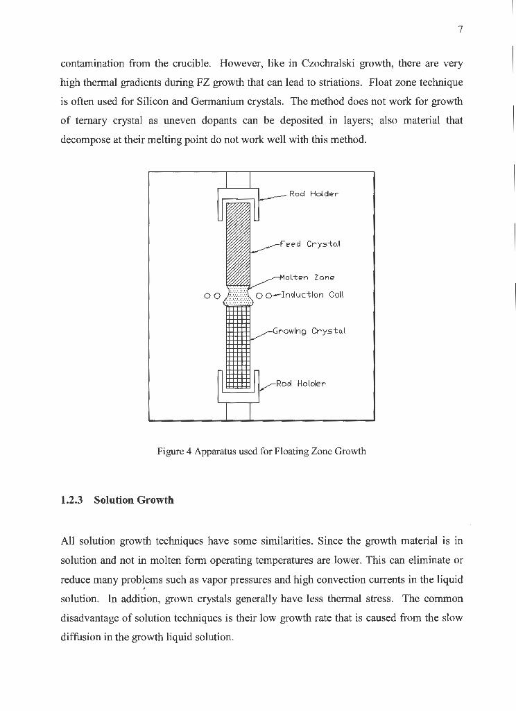
7
contamination from the crucible. However, like in Czochralski growth, there are very
high thermal gradients during FZ growth that can lead to striations. Float zone technique
is often used for Silicon and Germanium crystals. The method does not work for growth
of ternary crystal as uneven dopants can be deposited in layers; also material that
decompose at their melting point do not work well with this method.
Rod Holde r
F eecl Crys-t o. !
Mol tE'n Zone
con
Growing Crysto.l
Figure 4 Apparatus used for Floating Zone Growth
1.2.3 Solution Growth
All solution growth techniques have some similarities. Since the growth material is in
solution and not in molten form operating temperatures are lower. This can eliminate or
reduce many problems such as vapor pressures and high convection currents in the liquid . solution. In addition, grown crystals generally have less thermal stress. The common
disadvantage of solution techniques is their low growth rate that is caused from the slow
diffusion in the growth liquid solution.

8
1.2.3.1 Traveling Heater Method (THM)
Like all solution growth methods THM induces crystal growth by supersaturating a
solution of the growth material. In the case of THM, lowering the temperature of the
solution on the interface between the seed crystal (in the case of seeded growth) and the
solution create this supersaturation. As this growth interface progresses forward so does
the temperature profile, continually maintaining a lower temperature at the crystal
solution interface than the rest of the liquid solution. Coinciding with this moving
temperature gradient that advances with the growth interface, is another temperature
gradient that increases the temperature at the liquid-source interface (dissolution
interface), continually dissolving more source material and maintaining a constant solute
concentration in the liquid solution. See Figure 5. This ability to maintain a stable solute
concentration during growth is a major advantage of the THM growth method.
Direction of Motion-----
Ar"lpoule ----"""
Henter-.
Figure 5 THM Growth Apparatus
In order to achieve the growing conditions described in the above section, an axial
temperature profile with a spike or bulge must be created. The most important part of the
temperature profile spike is the gradient of the leading slope. It is this gradient that

9
causes the supersaturation in the solution resulting in crystal growth, therefore it plays an
important role in the growth rate, along with concentrations in the vicinity of growth
interface. This gradient can also cause and increase the magnitude of buoyancy driven
convection currents. These currents can lead to a concave shape of the growth interface, 5
a situation that can trap impurities and dopents in the crystal lattice leading to flaws or
polycrystalline materials. In the case of seeded growth, the precise position of this
gradient with respect to the growth seed is essential but difficult to obtain in experiments.
The gradient in THM is achieved by heating an area of the growth furnace while cooling
another just below it.
t z
~ Si02 Crucible
i
i r
• Source
3.3 \
\ ' \
2.8
2.3
45 1.8
I 1.3 mm
Solution
Substrate
J /
/
:c~.Q 0.8
0.3
-0.2
J
I -0.7
2
mmTI ..... ---·I 1-13 rrm 2mm
·1.2 400 500 600
Temperature ("C)
Figure 6 THM Ampoule and Temperature Profile (Meric et. al. 1999)
The typical temperature profile used for THM growth can be seen in Figure 6. A furnace
holds an ampoule mounted either horizontally or vertically, with one torus shaped heating
element positioned' around it. On the growth side of the heaters the furnace is cooled by
conduction and typically has little or no insulation. In some cases direct contact is made
between the ampoule and some cooling fluid or a high conductivity metal bar, rod or
plate that is cooled by some other medium.6 The ampoule is mechanically moved at a
10
constant rate between 1 and 4 mm per day through the furnace until all of the feed
material has been melted and deposited as new crystal. A variation of this setup is one
where the temperature profile of the furnace can be changed. Closely positioned
independently fired resistance heaters are positioned around an ampoule. The heaters are
consecutively fired in such a way as to move a temperature spike forward while the
ampoule remains still. This system has the advantage of having no mechanical moving
parts, which makes it vibration-free. Vibration has the potential to disturb the growth and
lower crystal quality.
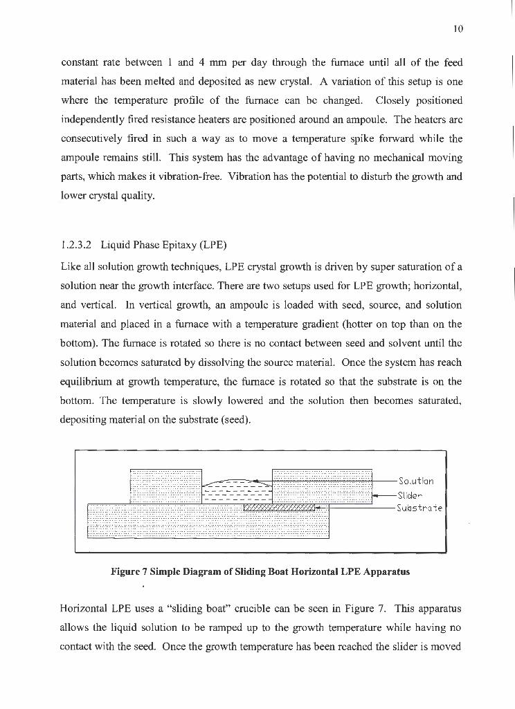
1.2.3.2 Liquid Phase Epitaxy (LPE)
Like all solution growth techniques, LPE crystal growth is driven by super saturation of a
solution near the growth interface. There are two setups used for LPE growth; horizontal,
and vertical. In vertical growth, an ampoule is loaded with seed, source, and solution
material and placed in a furnace with a temperature gradient (hotter on top than on the
bottom). The furnace is rotated so there is no contact between seed and solvent until the
solution becomes saturated by dissolving the source material. Once the system has reach
equilibrium at growth temperature, the furnace is rotated so that the substrate is on the
bottom. The temperature is slowly lowered and the solution then becomes saturated,
depositing material on the substrate (seed).
Figure 7 Simple Diagram of Sliding Boat Horizontal LPE Apparatus
Horizontal LPE uses a "sliding boat" crucible can be seen in Figure 7. This apparatus
allows the liquid solution to be ramped up to the growth temperature while having no
contact with the seed. Once the growth temperature has been reached the slider is moved
11
over the seed and the temperature dropped gradually to induce precipitation on the seed.
In some systems multiple sliders make it possible to grow several layers consecutively.
Apart from the basic advantages that are common to all solution growth techniques LPE
is also one of the most inexpensive methods to start-up and operate. There is no moving
of the ampoule, eliminating a possible cause of vibration and additional apparatus
components. The furnace used is simple to manufacture and requires a reasonably simple
controller. There is a limit to the size of crystal that can be grown by LPE, since once all
the material in the solution is depleted, the growth stops. This feature along with the
slow rate of growth common to all solution techniques restricts the use of LPE to
specialized applications. An exception to this is the innovative "yo-yo" method of LPE
growth, introduced by researchers in Shizuoka University, Japan; it allows the growth of
crystals 20 times thicker than classical LPE 789 . Due to the significance of this technique,
a large numerical of simulation models have been developed 1011 •
There are some instances where consecutive layers of crystal with varying composition
and properties are required. Examples include transistors and crystals used for laser
generation. Horizontal LPE is commonly used to deposit consecutive layers of doped,
undoped or highly doped materials on a seed. The flat growth interface and uniform
properties of materials grown by this method make it feasible, and since these layers are
typically very thin the low growth rate does not constitute a disadvantage.
1.2.3.3 Liquid Phase Electroepitaxy (LPEE)
The set up of LPEE growth is similar to THM in many respects, however the driving _
mechanisms are different. Like THM, the LPEE crucible is set up with a seed and source
with solution in-between, there is a continual growth on the seed and the source is slowly
dissolved in the solution (Figure 8). This keeps the concentration in the solution close to . constant. LPEE does not use temperature gradients to induce supersaturation and initiate
growth, instead the entire crucible is held at a constant temperature and a direct electric
current is passed through the solution and seed. This current induces crystal growth by

12
three methods 1) dissolving the source due to localized Peltier heating, 2) transport by
electromigration due to the electrostatic field 3) supersaturating the solution at the growth
interface by Peltier cooling.
Nego. tive Elec t rode
Co.rbon Electrode
Source --------+'h'--Tv.<r~
Source Bypuss-----v l'-'--'-""'--'--'I --------Solution----------+---1---_-_-_-_-_-_-_
Boron Nitru t e Crucible Substrute-------+--- --------
Conto.cteci Zone ------i:::;::::;:~J77,~7T77-,~l-,_-.----,--J
Curbon Electrode ---1
Positive Electrode
Figure 8 A Typical LPEE Crucible Setup
The advantage of LPEE growth is the high quality of the crystal grown, typically having
both high purity and very low thermal stresses and dislocations. The growth apparatus is
simpler and cost less than most vapor growth techniques, and growth rates can be faster.
Thus far, in the literature, the major disadvantage of LPEE was considered to be the small
size of the growth layers. Growth of between 3 and 5 mm was thought to be the
maximum possible as the Joule heating in the grown crystal starts to create problems with -
thermal gradients as the crystal get thicker. However, a state-of-the-art LPEE facility
developed at the University of Victoria (Crystal Growth Laboratory) has recently led to
the growth of ver{ thick (up to 10 mm) ternary crystals. Researchers have been able to
increase LPEE growth rates more than 10 times, with the combined effect of unique
crucible designs and the use of external magnetic fields. Such developments in LPEE
growth are making it a "bulk" growth technique.

13
1.3 Solution Concentration
As stated previously saturating the solution near the growth interface induces crystal
growth in THM. The solute concentration in the small region near this interface is of
great importance since it plays a major role in the rate of growth and the quality of the
crystal grown. Figure 9 presents the variations of the solute concentration (CL),
temperature (TACT) and saturation temperature (T EQ) at and near the growth interface.
The solute concentration here could represent any element present in the solution
including dopents and impurities.
// // /,
_..;------- T AL'
-----1---+-----CL
------- TACT _.......ii-.:-:,.,.....c;--t----- TEO.
I
I I
w ~~
(al
(bl
Figure 9 Concentrations under stable (a) and unstable (b) growth conditions (Hurle 1994)

14
Differences in solubility and the concentration in the crystal can cause some components
to be at higher concentrations near the growth interface. It is not desirable to have high
impurity concentrations in this region. However, without a forced mixing, the only
mechanism to disperse the impurity is diffusion which is typically very slow in liquid
metals. In order to have a practical growth rate (higher than 1 mm per day) the ampoule
must move at a speed that will result in some concentration gradients. The saturation
temperature is a value at which any temperature above will result in a undersaturated (and
anything below an supersaturated) solution. During most crystal growth, there is some
supersaturation in the vicinity of the growth interface. However, an excessive amount of
solute will lead to rapid uncontrolled growth that could result in solvent inclusions and
the development of polycrystalline material. The small hatched region in Figure 9b
represents the degree of supersaturating and it should be kept to a reasonable amount.
Keeping a steep temperature gradient in the solution can help to do this, as well as
promoting forced mixing to reduce the concentration levels near the growth interface.
Alternatively, a slower growth rate can be used; however, economically faster growth
rates are better.
1.4 Contamination Considerations
High quality crystals must have high levels of purity. Since most crystal growth materials
will oxidize at elevated temperatures an oxygen free growth environment must be
provided. A vacuum is commonly used for this purpose. The ampoule is sealed at low
temperature and a vacuum is applied through a valve at the top, limiting the amount of
available oxygen in the ampoule. In cases where higher purity is needed hydrogen or
some other reducing gas environment is used as a chaser. The ampoule is flushed through
with hydrogen and then a vacuum is applied to remove any water or other impurities.
Often this step is repeated several times. The use of hydrogen has some safety issues . associated with it and, therefore, safety precautions should be taken. These include all
necessary sensors and alarms.

15
1.5 Control of Growth Conditions
Similar to many fields, crystal growth has been under an ongoing pressure to increase the
quality of its products. One of the methods that crystal manufactures and researchers
have been investigating to control the growth conditions that influence the grown crystals
is the use of magnetic fields. The application of external magnetic field influences the
growth conditions in two ways. First, it suppresses the buoyancy driven convection in the
solution that can lead to an unstable growth interface. Such conditions can cause solvent
inclusion, nonuniform material concentration or polycrystalline growth. Secondly, the
application of magnetic field gives rise to controlled mixing in the solution. Controlled
mixing can reduce concentration gradients within the growth cell that can lead to unstable
convection currents. It distributes solutes uniformly throughout the solution, making
them available for growth. This helps to increase the rate of growth, and leads to a grown
crystal with more uniform compositions.
One drawback of THM crystal growth is its low growth rate. This is due to the slow rate
of solute diffusion in the solution. Suppressing the convection by means of applied
magnetic field would further reduce transport in the solution and slow down the growth
rate. However, high convection currents have been attributed to the development of a
concave growth interface, which inevitably leads to a lower crystal quality. In an
idealized situation there would be a slow but controlled mixing in the growth cell,
whether by natural convection or induced by a magnetic field. Such controlled mixing
would not induce a concave growth interface, but would eliminate temperature and
concentration fluctuation at the interface. In tum, a stable growth concentration would
minimize growth striations and non-uniform dopant concentrations. The mixing would
also help increase the maximum growth speed. In order to achieve such ideal growth
conditions, a complete understanding of convective flows induced from gravity, fixed
and rotating magnetic fields is needed. Once this knowledge is gained, a combination of
both rotating and fixed magnetic fields controlling the buoyancy driven convection may
be able to help in achieving the aforementioned growth conditions12•

16
1.6 Rotating and Static Magnetic Fields in Crystal Growth
Many researchers have used magnetic fields in both the axial and transverse directions to
dampen convection flows and turbulence. A good body of research is focused on the
Czochralski growth since the crucible used in this method is subject to high temperature
gradients and therefore strong convection currents. These currents are responsible for
uncontrolled temperature fluctuations at the crystal growth interface that cause
nonuniform striations in the grown crystal. 13 It has been shown that a magnetic field of
0.1 T can reduce the temperature fluctuations at the growth interface from 9 to 0.3 °c and
make marked reductions in resistivity fluctuations in some semiconductor crystals grown
by the Czochralski method. However, axial magnetic fields have been seen to degrade
the radial symmetry in the grown crystal and transverse fields can destroy the thermal
symmetry and introduce rotational striations, in Czochralski growth. From the research
done with fixed magnetic fields in Czochralski growth it is clear that they have the ability
to dampen currents in the melt, however their negative effects on concentration
uniformity due to reduced mixing is also considerable.
Most work done on other growth methods is numerical. Dost and Sheibani 14 preformed a
numerical simulation of the LPEE growth of GalnAs with and without magnetic field (up
to a 2 tesla field). The results showed a decrease in convection current velocities of 1000
orders of magnitude. This leads to a much more stable growth interface that was close to
flat. Studies without magnetic fields showed two humps on the growth interface due to
faster growth from higher concentrations caused by convection currents. This work not
only shows that convection currents can be suppressed by a magnetic field but also that
these currents have both good and bad effects. The currents can increase growth rate by
increa~ing transport in the solution, but if this increase is not even over the entire crystal
an uneven and unstable growth interfaces can result, leading to solvent inclusion and
uneven concentrations in the grown crystal.
Mobner and Gerrbeth15 did a numerical simulation of melt growth under both fixed and
rotating magnetic fields. They found that a great variety of controllable flow structures

17
were possible from any thermogravitational conditions, with the right strength and
frequency of magnetic fields. This suggests a great opportunity for optimal crystal
growth under the influence of both fixed and rotating magnetic fields.
1. 7 Numerical Modeling
a) b) c)
Figure 10 Connective Cells in Growth Solution under a) gravity and zero field b) zero gravity and zero field c) gravity and a RMF (Senchenkov 1998)
r . :'\ I k)I~
a) b) c)
Figure 11 Connective Cells in Growth Solution under a) gravity and zero field b) gravity and a RMF c) zero gravity and a RMF (Microgravity News 199716)
Much numerical research has been done to try and find the effect of growing crystal from
solution under the influence of a rotating magnetic field. Most of the numerical studies
done show that rotating magnetic fields can induce or control mixing currents in liquid
solutions. 17•18•19 This in tum leads to a stable and controlled solution-growth interface,
better crystal homogeneity, and a faster growth rate. Numerical results are further

18
supported by growth experiments done on both liquid phase and solution growth
techniques. There is some uncertainty as to how strong a magnetic field is needed and at
what rate it should rotate. These parameters could change depending on ampoule size
and material being grown. Generally magnetic fields strengths between 2 mT and 15 mT
and rotations between 50 and 400 Hz have been considered for rotating fields and
between 0.5T to 5 T for steady magnetic fields. An experimental study done with
CdHgTe by Senchenkov et al. 20 with a 2 mT magnetic field rotating at 400Hz grow
crystals with much lower standard deviation of mole fraction than crystals grown without
the RMF. There is not complete agreement between the results of all of the published
work. The results of two different numerical models of the solution cells in THM are
shown in Figure 10 and 11.
1. 8 Literature Review
Researchers at the Chalk River Nuclear Laboratories in Canada used both the LPE and
THM to grow CdTe for nuclear detectors. In their study published in 197721 they found
that temperature gradient and growth velocity had the greatest effect, but were not the
only parameters that influenced the number and size of Te inclusions in their crystals.
Their experiments concluded that both LPE and THM could be used to grow inoculation
free crystals if growth speeds where kept between 2-3 mm/h and temperature gradients
above 5°C Imm. Their work fails to address other crystal quality concerns such as
composition homogeneity and grain size.
Benz and Muller grew both GaSb and InSb by THM in the vertical and horizontal
position.22 Their work focused on the effect of different solution lengths. By varying the
amount of solvent put in the charge the length on the solution would change; this in tum
changes the radius of the growth interface. They found an optimum radius of between 7 >
and 10 mm in their 10 mm diameter samples. This was obtained by fixing the
temperature profile and varying the solution length between 5 and 8 mm. Growth rates in
19
the experiments were varied between 0.7 and 5.0 mm/day, with 2.5 mm/day being the
fastest rates to yield inclusion free single crystal.
Similar work was done by Bischopink and Benz with InGaP and published in 198923•
Their experimental design made use of a 300W halogen lamp focussed on a 15 mm
diameter ampoule. The apparatus successfully grew InGaP crystals between 0.8 and 1.44
mm/day. The length of the crystals grown is not given, but all of the analysis was done
with the first 2 mm of growth suggesting only thin layer where achieved.
Bischopink and Benz published another work in 1991 with AlGaSb24 • They used a
similar furnace to the one in their 1989 work and grew crystals up to 17 mm long. Their
longest single crystal was 112 mm long. Growth rates varied between 1.0 and 1.44
mm/day.
Bukert, Gille and Kiessling published a paper in 1991 that focussed on feed material
preparation for THM runes with HgCdTe. They used Bridgman growth followed by
VGF to remove any Te inclusions. Both of these growth procedures were performed in
the same quartz ampoule without allowing the crystal to completely cool. The crystal
was then cooled and removed from the ampoule, etched and used as feed material in a
THM run moving at 1 mm/day. Their 16 mm diameter crystals showed good
composition uniformity with standard deviations in mole fraction varying by as little as
.003 in the axial direction and .005 in the radial.
There are only three known furnaces capable of growing crystals under the influence of a
rotating magnetic field. All three were designed at the Splav Technical Center in
Moscow Russia.25 ZONA 4 is the oldest and is capable of growing crystals between 400- _
1300 °C with feed rates between 0.15-15 mm/h, makings it suitable for zone melting and
THM. This furnace has a mass of 50 kg and maximum power output of 200W, it is
capable of growing between 4-6 crystals and has been on several unmanned space . missions to grow crystals in micro gravity. Some of the experiments that have been run
will be discussed later. ZONA 8 is a much larger furnace with a mass of 100 kg and a
maximum power of 1400W26• It is capable of growing up to 10 crystals under a rotating

20
magnetic field. This author has been unable to find any published reports of its use. This
may be due to economic pressure on the Splav Technical Center in Russian since the
furnaces scheduled completion date of 1996. SKAT-AG is still larger, with a mass of
250 kg and a max power rating of 4500 W. Capable of growing up to 10 crystals under
both fixed and rotating magnetic fields it is scheduled for use in a joint Russian-German
project. Again, this author was unable to find any details about work done with this
furnace. It is reasonable to assume that experimental land based furnace designs were
used prior to the development of these space furnaces, but no published work has been
found on such equipment.
In October of 1991 the unmanned PHOTON 7 space mission carried the Soviet built
ZONA 4 furnace into space to grow CdTe in micro gravity27• Two crystals were grown,
the first had 50-mm of feed material grown on a 15mm long seed under the influence of a
rotating magnetic field for 100 h. The other crystal had 25 mm of feed material grown on
a 15-mm long seed for 50 h without any magnetic field. Both crystals were pulled at a
rate of 0.27 mm/h (6.48 mm/day) and grown at 750°C. The magnetic induction was 2
mT with a frequency of 400 Hz. Changes in axial resistivity were lowest in the crystal
grown in micro gravity with the rotating magnetic field when compared to growth with
and without gravity and magnetic fields.
In 1994 Salk, Fiederle, Benz, Senchenkov, Egorov, and Matitioukhn reported the results
ofresearch using ZONA 4 to grow CdTeSe in micro gravity28• A crystal was grown with
a 0.27 mm/h (6.48 mm/day) pull rate for 100 h (4.2 days). For the first 50 hours of
growth a 2 mT magnetic field rotated at 400Hz frequency. The field was turned off for
the second half of the growth. The crystal was much more homogeneous in the first half
of its length, which also had less dispersion in its resistivity measurements when
compared to all other crystals grown with or without gravity.
Senchenkov, Barmin, Tomson, and Krapukhin ran a series of ground-based experiments
growing CdHgTe in ZONA 4 with and without rotating magnetic fields. Their findings,

21
published in 1998, stated that crystal composition uniformity was greater with the 400 Hz
rotating magnetic field between 2 to 6 mT compared to crystals grown with no field. 29•
22
1.9 Cadmium Zinc Telluride (CdZnTe)
1.9.1 Applications
There are three main areas of interest for CdZnTe. The first is as a substrate for HgCdTe
infrared detectors30. Secondly, as a detector in high-resolution x-ray computed
topography3 1, and lastly CdZnTe has great promise as a gamma detector for use in
nuclear medical imaging and other radiation detection devices. 32
The fabrication of CdZnTe was first established for use as a substrate material for
HgCdTe infrared detectors. This state of the art detector forms the focal plane arrays used
in Nag missile guidance systems, and plays an important role in military systems used in
target acquisition, identification and tracking. For this reason the production of CdZnTe
has received attention from bodies like the Defence Research & Development
Organization (DRDO) in the United States. The DRDO is developing production centers
for CdZnTe to achieve self-reliance in what they believe to be a "critical material"33.
X-ray diagnostics measure the intensity of a transmitted x-ray beam to create images.
The standard technique of irradiating the patient with an x-ray beam and producing the
image on photographic film is well known and used. However, with the use of radiation
detectors, computers and image processing techniques, photographic film can be replaced
by computerized tomography (CT) radiographic imaging systems. One of the advantages
of such a system is a substantial reduction in processing time allowing the image to be
viewed almost immediately. Also, with CT radiographic imaging it is possible to
produce consecutive two-dimensional slices of a three-dimensional object. This is a great
improvement over standard x-rays where a complete picture of an object is possible but
not a slice or section. There are several different materials of interest for CT scanning,
including CdTe, CdZnTe, CsITi, and CdW04. Preferred crystals can vary depending on
applications. CdZnTe has been used successfully in some applications though its use is
limited by a long after glow34. At the Oak Ridge National Laboratory a prototype single-

23
pixel CdZnTe detector has had good success in identifying mutagens in lab mice35, most
CdZnTe x-ray detectors remain in the research and development stage36.
Materials used for gamma ray detectors require two properties. The first is efficient
gamma absorption. Heavier elements such as Cd and Te have better absorption than
lighter ones like Ga and As that have been traditionally used as gamma detectors. The
second property required in a detector is efficient collection of the electrical signal
generated by absorbing a gamma photon. This property is related to the energy band gap
of a material. Energy band gap is a measure of the energy required to mobilize electrons
in a material. Therefore the energy band gap of an electric conductor would be zero and
that of and insulator large. With semiconductors, some electrons can move by virtue of
energy from thermal vibrations. In gamma detector electrons moving due to thermal
vibrations creates a signal known as "electrical noise". This noise is superimposed over
the signal created during the gamma absorption process and leads to signal degradation
and poor resolution. Both Ge and GaAs have a low energy band gap and must be cooled
to cryogenic temperatures to reduce thermal vibrations and electrical noise in order to
obtain reasonable resolution. This means that any Ge or GaAs based gamma detector
will have the size, complexity and cost of a cryogenic cooling system associated with it.
CdZnTe has a large energy band gap and high thermal conductivity at room temperatures,
so no cryogenic refrigeration is required. It is also more sensitive than Ge or GaAs to
gamma rays. This means that for medical applications, patients require lower doses of
radioactive isotope. This makes CdZnTe ideal for use as a gamma ray detector. The
greatest limitation to the wide spread use of CdZnTe is the availability of large numbers
of homogenous single crystals. This is due to the material's thermal properties that make
it difficult to grow. One other material suitable for gamma-ray detectors is Hgh. Because
of the high volatility of both Hg and I this crystal is very difficult to grow in single crystal
form and has only been done by condensing the elements from vapor. Vapor growth is
typically costly a~d slow making Hgh an unattractive alternative considering the large
volumes of crystals needed in gamma detectors.

24
One of the principal applications of gamma ray detectors is for Gamma-ray cameras used
in nuclear medical imaging.(NMI) There are several advantages of nuclear medical
imaging over other imaging procedures such as general radiology, CT and magnetic
resonance imaging (MRI). These technologies are able to produce a two-dimensional
picture and in some cases consecutive slices of a three-dimensional object but not the full
three dimensional picture that is possible with nuclear medical imaging37. Also with
nuclear medical imaging it is possible to measure the function of a body, not just its
anatomy. An example of this is assessing a gallstone. There are different ways to
determine the size and the exact location of a gallstone, but only NMI techniques can
conclude whether or not the stone is inhibiting the movement of fluid in the gallbladder38.
To produce an image a radioactive pharmaceutical is injected or taken orally by the
patient. This radiopharmaceutical is tagged to a compound that has an affinity for the
organ of interest. A gamma-ray camera is then used to create an image or scan of the
distribution of the radiopharmaceutical. Radiologists look for absences or excessive
distribution, indicating a diseased area. There are two basic layouts for nuclear medical
imaging cameras. The conventional system uses Nal crystals that produce small flashes
of light known as scintillations when impacted by a gamma ray. The first scintillation
type cameras (still widely used today) was developed in 195839. Photomultiplier tubes
pick up the scintillations and convert the light signal to an electric current. This current is
converted to a digital signal that is interpreted by a computer algorithm and displayed. A
CdZnTe, GaAs or Ge camera produces a digital signal directly from the impact of a
gamma ray with the crystal. This signal can be fed directly to the computer algorithm
with minimal signal processing. This is a more efficient process than conventional
gamma cameras allowing lower radioactive isotope doses to be used. The removal of the
photomultiplier tubes from the system also decreases the size, weight and cost
considerably.
There is a wide range of other applications for gamma ray detectors. Geo-steering is a . method of drilling for oil where a gamma ray counter measures the radioactivity in the
drilling slug. With knowledge of the radioactiveness of different rock types, drill heads
can be more accurately steered toward oil reserves40. Since CdZnTe based gamma ray

25
detectors would not require any bulky cryogenic refrigeration systems, they would be
transportable and ideal for monitoring radioactive waste storage or verifying nuclear
treaties4 1 42. Another interesting application is gamma ray astronomy, where
astrophysicists hope that the unprecedented accuracy of CdZnTe gamma ray detector
arrays will unlock the mysterious source of gamma ray bursts 43 .
Material Band Gap ( e V) Resistivity (Ohm-cm)
CdZnTe 1.56 lO'J to 1010
CdTe 1.47 8.3*103
Hgl2 2.13
GaAs 1.42 107 to 108
Ge 0.67 47
44, 45 46
Table 1 Some Properties of Gamma Detector Crystals
1.9.2 Production
CdZnTe is produced commercially by several compames, each one having its own
specific set of growth techniques. The specifics of a company's chosen techniques are
kept secret and will not be discussed here. High Pressure Bridgman is by far the most
popular method for bulk production of CdZnTe. In the United States companies such as
eV Products and Digirad use this method47 48 as well as many experimental institutions
such as The Institute of Single Crystals in Khainr, Ukraine, and Institute of Solid State
Physique in Moscow, Russia 49 and University of Victoria's Crystal Growth Research
Group in Victoria, Canada. Vertical Bridgman is also used by eV and Keystone Crystal
cooperation. The latter company is also known to use Czochralski growth for CdZnTe50.
There is also ongoing research into the use of Vapor Growth, THM and LPEE, but there
is no known produ~tion by these methods.
26
1.10 Purpose and Outline
The objective of this thesis was to design and build a furnace capable of growing one
inch diameter CdZnTe crystals while varying a number of growth parameters. The
furnace was to allow a researcher to grow the required experimental crystals so that
optimal growth parameters can be found to maximize crystal quality and speed of growth.
The different growth parameters that can be obtained with the furnace are as follows.
• Temperatures between 750 and 950 °C
• Linear translation rates between 1 and 10 mm/day
• Temperature gradients between 100 and 1000 °C/cm
• Rotating magnetic fields between .5 and 2 mT and 5 to 150 Hz
• Fixed coaxial magnetic field between 0 and 2 T (added in the future)
• The application of acoustic wave mixing (added in the future)
This thesis contains
• An overview of crystal growth techniques.
• An outline of the uses of CdZnTe.
• A Summary of the work done on the use of the THM.
• Description of the thermal modeling work done on THM design at the University of
Victoria
• Description of the THM furnace design and operation at the University of Victoria
• Conclusion and future Improvements

27
2 Thermal Analysis by the Finite Element Method
2.1 Introduction
The need for a thermal model of the THM furnace stems from the importance of
temperature gradients in crystal growth. The commercial software Ansys 5.7 was chosen
for its reliability, speed and availability at the University of Victoria. There is a lack of
knowledge of the optimum growth conditions for THM crystal growth. This means that
the model needs only to give a general idea of the temperatures that the crystal and
growth solution would be subjected to. Any further accuracy would be superfluous. For
comparison, a model was developed for an existing THM furnace design that is used by
Amistar Research and Development Inc. of Victoria to grow CdZnTe. It was felt that the
performance of this furnace could be improved by increasing the temperature gradient
between the hot (middle) and cold (bottom) zones51 , see Figure 6 in the first chapter.
Three models will be presented here, the first is a two-dimensional model of one half of
the Amistar furnace, the second is a similar model of a proposed sloped cooling block
design. The final model is of the layout chosen for the THM-1 furnace. It incorporates
the extended cooling block seen in the second model with more insulation and less
unnecessary heating of the cooling block.
2.2 Model Development
Several trials of three dimensional models were made. They were found to be slow on the
available computers (Pentium 200MHz, 64MB RAM) and almost exhausted the
computation powe~ of the student version Ansys 5.7 software being used, even at course
grid sizes. All models were therefore done in two dimensions. This introduces some
inaccuracy into the model.
28
Some assumptions were made to simplify the model. It was assumed that all sides of the
furnace were adiabatic except the areas around the heater and the outside face of the
cooling block, where heating and cooling are supplied to the furnace. These areas have
known temperatures that will be fixed by applying loads. They are also the areas with the
highest heat fluxes and will have the greatest effect on the temperature profile. The top
and bottom of the furnace as well as the outside of the insulation were assumed to be
adiabatic. This is an assumption that will introduce some inaccuracy into the model.
However, since the most important information is the temperature gradient in the center
of the furnace the effect of heat transfer on the outside of the furnace would produce little
change. It was also assumed that the inside surface of the furnace would be adiabatic,
this is a poor assumption since there is a high temperature gradient present here and the
liquid metals in the charged ampoule would have an effect on the temperature
distribution. There are two reasons that this simplification was made. The first is because
of the difficulty in modeling the interactions between the crystal and both the hot and
cold areas of the furnace. Inside the ampoule there are phase changes and convection
currents (possibly coupled with magnetic field currents), the modeling of which is far
beyond the scope of this thesis. There is radiation and convection between the furnace
and the ampoule, both of which are difficult to model and are dependent on the condition
at the surface of the ampoule. The second reason that the inside of the furnace was
assumed to be adiabatic was that furnaces are sometimes "characterized" by running a
thermocouple up the inside of the furnace while it is running at operating temperatures
loaded with an empty ampoule. The purpose of this characterization run is to get some
idea of the temperature profile of the furnace enabling comparisons between furnaces.
The empty ampoule reduces convection and helps to create a standardized method.
Characterization runs also produce data that is used for modeling the interactions inside
the ampoule. The temperature profiles that are generated from the characterization are
superimposed onto a model of the ampoule charge. The model calculates fluid motion,
phase change, and concentrations inside the ampoule charge. It was therefore felt that . modeling the furnace under characterization type conditions would be useful on a
comparison basis. The contact resistance between all the components of the furnace were

29
also neglected. It was felt that this would not introduce a large error relative to some
other approximations that were made.
Loads were applied to the furnace by fixing the temperature around the areas that would
be in radial contact with the heater to 1170°K (896°C) and the outside surface of the
cooling block to 303°K (30°C). This was the simplest way to accurately portray how the
furnace will be run. In the real furnace the heater is in contact with a thermocouple.
Therefore the thermocouple reading is the same as the heater. In the model the
temperature is applied directly to the walls surrounding the heater; this temperature
would be lower than that of the heater. Since the furnace will be run at temperatures
between 750 and 950 °C this difference is not considered important. The cooling block
will be cooled to maintain a constant temperature at a decided level. One advantage of
the furnace design is its ability to change the temperature of the cooling block. This
allows experiments comparing crystals grown under different temperature gradients.
The model fixed the outside temperature of the cooling block at 30°C since this is a
reasonable value and one that can be compared to existing Amistar THM furnaces.
2.3 Mesh Generation
® ___ ..:..---7K
y
or Axial) 1 ------:::::----__j L CD X (or Radial)
PLANE55
Figure 12 Ansys PLANE55 Planer Element
/

30
Initially two different Ansys planar elements were used to mesh the models. The first,
PLANE 55 is a two-dimensional linear thermal conduction element with four nodes and a
single degree of freedom, temperature, at each node. The second, PLANE 77, is a higher
order 8 node thermal conduction element. It also has one degree of freedom, temperature
and is well suited for modeling irregular shapes. It was found that the linear PLANE 55
gave efficient results with the shapes modeled and a reasonably coarse grid. A
comparable grid with the higher order PLANE77 took longer to solve and gave similar
results. For this reason PLANE 55 was used for most of the models.
©
y or Axial)
L x '" R,,;,11 PLANE77
N
M J
Figure 13 Ansys PLANE77 Planer Element
Meshing size was contorted by the Ansys "ESIZE" command. This command divides the
length of each surface boundary by a given length, (rounded upward to next integer) then
divides the surface boundaries by the number calculated. This makes each surface
boundary divided into lengths that are equal to or smaller than the length defined by the
ESIZE parameter. Most runs were done with an ESIZE length of .002 (2mm) this
produced 1429, 1232 and 1326 elements and 5476, 3912 and 4190 nodes in the three
model's respectively. Some models were run with ESIZE length set at .001 (Imm)
(approximately 5284 elements) to make result comparisons and ensure fine enough grid . spacing. No noticeable differences in results were observed with the finer grid.

31
J\NSYS ll'OV l. 2:00 1.
Heater Location Ceramic Insulation
Aluminum Support
Cooling Block
2cm
THM Alllistar Prototype Furnace
Figure 14 Computational Domain of Amistare's Prototype Furnace
2. 4 Models Description
As has been stated three models were made and tested. The first can be seen in Figure 14.
This model is based on the furnaces used to grow CdZnTe at Amistar Research. The
model is narrower than the Amistar design to accommodate the six rotating magnetic
field coils, and still have a small enough diameter to fit inside the fixed magnetic field
generator. The model will be used for comparison with other models. In Figure 14 the
black area represents the furnace liner, a quartz tube that runs the length of the inside of
the furnace. The gray area represents the aluminum cooling block and some aluminum
support structure. All dotted areas are ceramic insulation. A hole is left in the center of
the model representative of where the resistance heater will be placed. Loads are placed
on the four sides of this hole labeled "Heater Location".
Furnace Liner ---
Heater Location
2cm f---------1
TllH Slopinq Coolinq Block Desiqn
J\NSYS IOU .l 200.l
Extended Cooling Block
Figure 15 Sloping Cooling Block Design
32
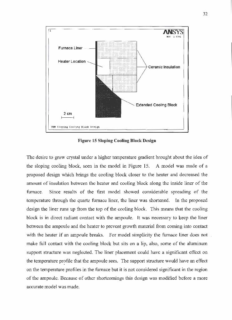
The desire to grow crystal under a higher temperature gradient brought about the idea of
the sloping cooling block, seen in the model in Figure 15. A model was made of a
proposed design which brings the cooling block closer to the heater and decreased the
amount of insulation between the heater and cooling block along the inside liner of the
furnace. Since results of the first model showed considerable spreading of the
temperature through the quartz furnace liner, the liner was shortened. In the proposed
design the liner runs up from the top of the cooling block. This means that the cooling
block is in direct radiant contact with the ampoule. It was necessary to keep the liner
between the ampoule and the heater to prevent growth material from coming into contact
with the heater if an ampoule breaks. For model simplicity the furnace liner does not
make full contact with the cooling block but sits on a lip, also, some of the aluminum
support structure was neglected. The liner placement could have a significant effect on
the temperature pr?file that the ampoule sees. The support structure would have an effect
on the temperature profiles in the furnace but it is not considered significant in the region
of the ampoule. Because of other shortcomings this design was modified before a more
accurate model was made.

34
selected convergence criteria of 1 O~ and the initial time step was set to two. The
algorithm automatically increases the number of time steps if large load increments are
obtained. The automatic time steeping algorithm was used exclusively and is thought to
give good convergence for these simple problem53• A variety of load step factors were
set using the Ansys "NSUBST" command. Higher numbers of load steps significantly
increased the computational time with no noticeable effect on the results. For this reason
a load step of one was used almost exclusively.
2.6 Results and Discussions
JleV l. tOOl.
303
399.333
49S . 667
S9Z
688 . 333
784.667
881
deg. K
Figure 17 Isothermal Plot of Amistar Furnace Design
Isothermal plots of the models can be seen in Figure 17, 18 and 19. There is a larger
thermal gradient between the cooling block and the heater in Figure 18 and 19 compared
to Figure 1 7. This indicates that the latter designs will be successful in producing steeper
temperature gradients between the heater and the cooling block, which were discussed in
the introduction of this chapter. Close inspection of the isotherms also shows them

35
"spreading" as they enter the quartz furnace liner (in black in Figure 14, 15 and 16). This
undesirable smearing of the temperature gradient was partly eliminated by removing the
lower half of the liner, in the second and subsequent models.
Figure 20 is a comparison of the temperature profiles of the Amistar furnace (Figure 14
and 17) and the final design (Figure 16 and 19). This graph was made from the nodal
solution along the inside surface of the two dimensional models. The higher temperature
gradient between the hot and cold zone in the latter design suggests the new furnace will
improve the growth conditions of the crystal compared to the prototype Amistar design.
l
'IlDl Slop1.11.g Coolinq Block l>es1gn.
Figure 18 Isothemals of Sloping Cooling Block
llOV J. zeu
303
399.333
495. 667
592
688.333
784.667
881
977. 333
1074
1170
deg . K
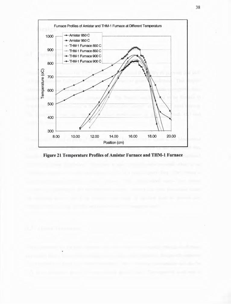
Figure 21 is a plot of the temperature along the axis of both the Amistar Prototype and
the final THM design. This information was obtained by ramping the furnace up to a set
point temperature and allowing it to stabilize. A type K thermocouple was moved along
the inside wall of the furnace and readings were taken every centimeter. In order to limit
the effect of convective heating or cooling blocks of insulation were cut to fit inside the

36
furnace liner. These blocks helped hold the thermocouple against the wall of the furnace
and helped suppress air movement. A similar procedure was used with the Amistar
furnace except no blocks were used. The top and bottom of the furnace liner was sealed
to reduce convection and the thermocouples were feed through the top cover and ran
along the wall of the furnace liner. As can be seen from the figure, the gradients are
higher in the new furnace than the Amistars prototype. This was expected from the
numerical studies and shows that the model adequately predicted the effect of design
changes relative to the prototype design.
l AN ..UV J. ZOOJ.
303
399.333
495.667
592
688.333
784.667
881
977.333
1074
1170
deg. K
THll Extended Cooling Block Design
Figure 19 Isothermals of Final Extended Cooling Block
The models made using Ansys 5. 7 and the finite element method were useful in
determining the effect on the temperature profile of different cooling block shapes. Even '
though the temperature profiles that were obtained may vary considerably from reality
due to some of the assumptions made to simplify the model, the results were still useful
in determining the effect of shortening the furnace liner and incorporating different

37
shapes of tails on the cooling block. The cross-sectional layout shown in Figure 16 will
be used as a basis for the furnace discussed in the subsequent chapter.
1000.00
900.00
800.00
700.00
Q: 600.00
! :J iii ... 500.00
8. E II ... 400.00
:n:>.00
200.00
100.00
0.00
30 35
Temperature Profiles of Different Furnace Models
40
f--Extended Cooling Block Design
1--Amistar's Prototypr Furnace
45 50 55 60
Position (cm)
65
Figure 20 Temperature Profile of Amistar and THM-l(values taken at model)
Furnace Profiles of Amistar and THM-1 Furnace at Different Terrperaturs
1000 -+- Amistar 850 C -+- Amistar 950 C
900
800
400
_.... THM-1 Furnace 850 C
"""*" THM-1 Furnace 850 C __.._ THM-1 Furnace 900 C
_l_-+- THM-1 Furnace 900_ CJ--_
300 L------------,..----------4--'\-+-----!
8.00 10.00 12.00 14.00
Position (cm)
16.00 18.00 20.00
Figure 21 Temperature Profi.les of Amistar Furnace and THM-1 Furnace
38
39
3 Design
3.1 Introduction
The design objective of the THM furnace was to obtain the ability of growing one inch
(2.5 cm) diameter CdZnTe crystals under a variety of growth conditions. This chapter
outlines the design of the furnace, a linear translating device, a rotating magnetic field
generator, stands and related components. The design was intended to be flexible to
enable later incorporation of a fixed magnetic field magnet and acoustic wave mixing.
The equipment was also made for future modification to grow two-inch (5.1-cm)
diameter crystals.
It was desirable that all parts of the design could be machined in house at the Mechanical
Engineering Machine Shop at the University of Victoria. Most of the equipment was
therefore made from aluminum. This material is reasonably priced and easily machined
with the available equipment. Aluminum is also a nonmagnetic material, which is an
important consideration since the furnace will be in a high magnetic flux. The furnace is
assembled almost entirely of 10-32 screws. This standardized screw size makes
assembling, maintenance and modification simpler. Screws that were positioned inside
the proposed bore of the fixed magnet were made of stainless steel, to prevent any
unwanted forces acting on them and distortion of the magnetic field.
3.2 Linear Translator
The requirement for the linear translator is that it moves the ampoule through the furnace . at constant steady speed while transmitting no unwanted vibration to the growth ampoule.
The ampoule will need to be moved between 1 and 10 mm/day downwards and also be
able to be positioned quickly between crystal growth runs. The approach used was to
40
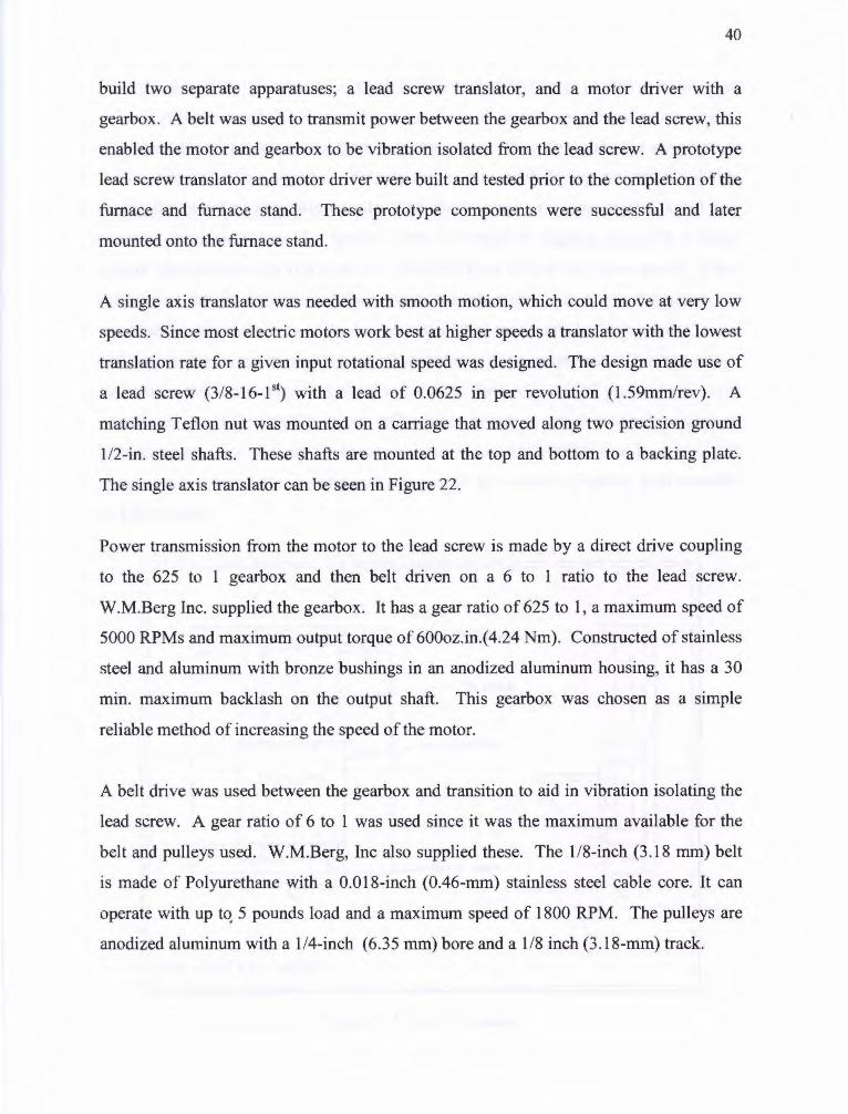
build two separate apparatuses; a lead screw translator, and a motor driver with a
gearbox. A belt was used to transmit power between the gearbox and the lead screw, this
enabled the motor and gearbox to be vibration isolated from the lead screw. A prototype
lead screw translator and motor driver were built and tested prior to the completion of the
furnace and furnace stand. These prototype components were successful and later
mounted onto the furnace stand.
A single axis translator was needed with smooth motion, which could move at very low
speeds. Since most electric motors work best at higher speeds a translator with the lowest
translation rate for a given input rotational speed was designed. The design made use of
a lead screw (3/8-16-1 51) with a lead of 0.0625 in per revolution ( l.59mm/rev). A
matching Teflon nut was mounted on a carriage that moved along two precision ground
112-in. steel shafts. These shafts are mounted at the top and bottom to a backing plate.
The single axis translator can be seen in Figure 22.
Power transmission from the motor to the lead screw is made by a direct drive coupling
to the 625 to l gearbox and then belt driven on a 6 to 1 ratio to the lead screw.
W.M.Berg Inc. supplied the gearbox. It has a gear ratio of 625 to l, a maximum speed of
5000 RPMs and maximum output torque of 600oz.in.( 4.24 Nm). Constructed of stainless
steel and aluminum with bronze bushings in an anodized aluminum housing, it has a 30
min. maximum backlash on the output shaft. This gearbox was chosen as a simple
reliable method of increasing the speed of the motor.
A belt drive was used between the gearbox and transition to aid in vibration isolating the
lead screw. A gear ratio of 6 to 1 was used since it was the maximum available for the
belt and pulleys used. W.M.Berg, Inc also supplied these. The 1/8-inch (3.18 mm) belt
is made of Polyurethane with a 0.018-inch (0.46-mm) stainless steel cable core. It can
operate with up to. 5 pounds load and a maximum speed of 1800 RPM. The pulleys are
anodized aluminum with a 1/4-inch (6.35 mm) bore and a 1/8 inch (3.18-mm) track.

41
Several types of motors were considered, mainly stepper and servo as well as fixed speed
AC and variable speed DC. Servomotors can move at precise speeds that do not change
with fluctuations in loads within their operating range. They do require the use of motor
driving circuits and an encoder. Stepper motors also need driving circuits, but do not
require the use of an expensive encoder. The disadvantage of stepper motors is that they
move in incremental steps that lead to jittery movement or cogging especially at lower
speeds. Servomotors can also have jerky movement but only at very slow speeds. It was
difficult to get any information from motor manufactures as to the performance and
smoothness of their motors at the low speeds. Most motor applications require torque
and positioning accuracy, and low speed smoothness is not important. This was one of
the reasons that a prototype was made and tested. Both AC and DC motors have a cost
advantage over other types. Slow AC motors (clock or timer motors) require no
connecting circuitry and can be directly connected to a 11 OV 60Hz power supply. DC
motors require very little circuitry and can operate at a variety of speeds both forwards
and backwards.
To~:+F=t=o:f:;::;:::;=<F=--"-SL 1 DEii SH.U TS
l_L4---1r----L £AD SC.11EW
= 0 0 AR II I AGE
T =
0 DR l't[ SHArT
lHM CRYSl AL GROWlH
Figure 22 Linear Translator

42
Two motor systems were designed and built. This will allow the operators to test both
systems and use the one that is the most successful, providing the most flexible design.
Both systems make use of a fast moving positioning 24V DC motor. This makes it
possible to quickly position the ampoule in the starting position in preparation of a
growth run. This DC motor drives the lead screw directly. The first system uses a stepper
motor to lower the ampoule. The motor speed is reduced by 3750 to one. This means
that the motor must tum between 1.6 and 16 RPM to move the translator between 1 and
10 mm/day. At these faster speeds the cogging of the stepper motor is hard to detect. It is
still an inherent property of stepper motors that they move in steps, therefore a second
drive motor was also supplied.
MOTOR
< > 0
COUPLI NG 0
0
= < >
0 0
[L[(.lRI(. CLUlCH
THM CRYSTA L GROWTH
Figure 23 Motor and Gearbox
The second lowering motor was an AC clock motor. It came with built-in gears of an
unknown ratio. The output shaft turns at a constant rate of three RPM with a 11 OV 60 Hz

43
power supply (no load). When attached to the same 3750 to 1 gearing this motor lowers
the ampoule at 1.845 mm/day. This motor is smooth in operation but lacks the flexibility
of the stepper motor. If other translation rates were desired they could be achieved by
using a different motor or changing the belt drive ratio. AC clock motors are reasonably
priced and can easily be salvaged from a variety of old equipment. They come in a
number of different fixed speeds. By varying the belt gearing between the existing 6 to 1
gear ratio and a 1 to 1 ratio, speed between the existing 1.85 mm/day and 11.08 mm/day
could be achieved, covering almost the full range of the desired 1 to 10 mm/day.
Since there are two motors connected to the same drive system it was necessary to
incorporate a clutch to disengage one of the motors while the other is operating. A 24V
electric clutch is located between the gearbox and the belt drive. When there is power to
the clutch the low speed motor operates the lead screw, overrunning the high-speed
motor. The control circuit was made so that it is not possible to run the high-speed motor
while the clutch is engaged. With no power to the clutch the high-speed motor can be run
and no power is transmitted to the gearbox.
3.3 Furnace
The main structural components of the furnace make up the casing which consists of a
112-inch aluminum top plate and bottom plate and the 1/2-inch aluminum cylinder shell
(see figure 24). This casing is the structural means to mount all other component of the
furnace. The bottom plate is mounted onto the shell and is tapped with 6 screw holes so
that it can be bolted directly to the stand. The cooling block hangs from a hole in its
center. Six ventilation holes are located between the potions where the magnetic
solenoids will be located. There are also holes so that the solenoids can be attached to the
bottom of the furnace. This will prevent them from moving and help provide good . thermal contact between the bobbins and the furnace bottom, helping to keep the magnets
cool. The furnace shell maintains the alignment of the cooling block and the top plate.
There are two tapped holes for attaching the ground wire to the inside of the furnace.

44
Nothing attaches to the outside of the shell as this could interfere with the permanent
magnet that will sit around the outside of the furnace. The top plate has a large center
hole where a marinite (ceramic) cap locates the furnace liner. This cap is held in position
by three aluminum positioning blocks. The blocks are bolted to the top of the plate and
are adjustable. Six terminal blocks are placed around the outside of the top plate to
connect the magnet solenoids to their power supply with accompanying holes to pass the
wires through. The top plate also has a plug for the heater power supply, ventilation
holes and a handle mounted.
TOP PLATE
SHEL L
~-~-COOL I NG BLOC K
THM CRYSTA L GROWT H
Figure 24 Cooling Block and Components of Furnace Casing
The cooling block is an integral part of the furnace since its shape and position will
change the temperature profile that the crystal will grow in. A copper tube with cooling
fluid pumped through it will provide cooling to the outside of the block. The block has
thick walls, and all boltholes are close to the outside to increase axial temperature
symmetry near the location where the crystal will grow.

45
The center bore of the furnace is lined with a quartz tube or furnace liner. This liner
keeps the cooling block, heater, and all ceramic insulation in place so there is a smooth
obstacle-free path for the growth ampoule to pass through. There is a small lip in the top
of the cooling block that the liner fits into and a marinite cap on the top of the furnace
that the liner passes though. This cap can be adjusted to ensure concentricity between the
cooling block and liner.
CE RAMI C FI RE BRIC K
MACHINED MARINIT[ RINGS
OOLI NG BL OCK
HEA1ER
THM CRYS TAL GROWT H
Figure 25 Exploded View of Ceramic Furnace Parts and Cooling Block
Two types of ceramic insulation were used in the furnace. Marinite is a calcium silicate
material made of fibers, micro silica and binders. It is highly damage resistant and
machinable54. Marinite was used around the tail of the cooling block and the heater since
it can be machined into the irregular shapes needed, withstand the high temperature in
this region and lasts well even under conditions of high temperature gradients and
thermal cycling. In the lower temperature area above the marinite, ceramic firebrick was
used. This less expensive material can not be machined. It was cut with a band saw to
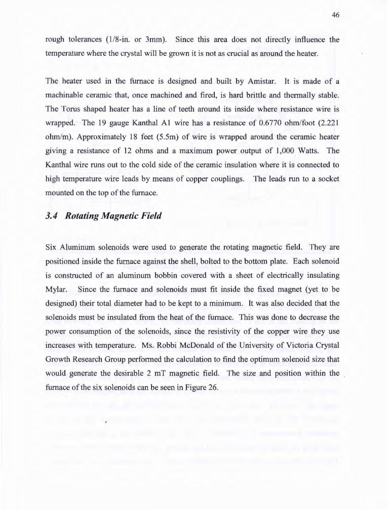
46
rough tolerances ( 1/8-in. or 3mm). Since this area does not directly influence the
temperature where the crystal will be grown it is not as crucial as around the heater.
The heater used in the furnace is designed and built by Amistar. It is made of a
machinable ceramic that, once machined and fired, is hard brittle and thermally stable.
The Torus shaped heater has a line of teeth around its inside where resistance wire is
wrapped. The 19 gauge Kanthal Al wire has a resistance of 0.6770 ohm/foot (2.221
ohm/m). Approximately 18 feet (5.5m) of wire is wrapped around the ceramic heater
giving a resistance of 12 ohms and a maximum power output of 1,000 Watts. The
Kanthal wire runs out to the cold side of the ceramic insulation where it is connected to
high temperature wire leads by means of copper couplings. The leads run to a socket
mounted on the top of the furnace.
3.4 Rotating Magnetic Field
Six Aluminum solenoids were used to generate the rotating magnetic field. They are
positioned inside the furnace against the shell, bolted to the bottom plate. Each solenoid
is constructed of an aluminum bobbin covered with a sheet of electrically insulating
Mylar. Since the furnace and solenoids must fit inside the fixed magnet (yet to be
designed) their total diameter had to be kept to a minimum. It was also decided that the
solenoids must be insulated from the heat of the furnace. This was done to decrease the
power consumption of the solenoids, since the resistivity of the copper wire they use
increases with temperature. Ms. Robbi McDonald of the University of Victoria Crystal
Growth Research Group performed the calculation to find the optimum solenoid size that
would generate the desirable 2 mT magnetic field. The size and position within the
furnace of the six solenoids can be seen in Figure 26.

47
BOBBINS lOP VE IW OF BOBBIN S LOCAlED IN FURNACE
1 'o 0
POSl1 10NING BRACk[T
3 7 000
25
I 7 I 25----
lH~[ADED HOLE FO~ t.40UM11MG 10 ru~N~CE BOTTO~
1HM CRYS1AL GROW1 H
Figure 26 Bobbin Location and Dimensions
The bobbins needed to have smooth surfaces to minimize the chance of damaging the
wire when they were being wound, be electrically insulated to prevent a damaged wire
from shorting out on the bobbin, be thermally conductive to aid in the cooling of the
solenoid, and be economical to build. Several materials were considered for use in
building the solenoid bobbins. These include aluminum, iron, machinable ceramic, and
plastics (Phenolic). An iron or steel core could have been used to focus magnetic fields
strength. This idea was not used since the metal core would have interfered with the
stronger fixed magnet with unpredictable reproductions. Machinable ceramic such as the
material used to make the furnace heater could have been used. However, the higher
purchasing and manufacturing costs made them impractical; they are also brittle and
prone to cracking if not handled with care. Phenolic is a thermosetting industrial
laminated plastic manufactured by heating and pressing layers of paper or glass cloth
impregnated with synthetic resin. It is a lightweight electrical insulator that has good

48
merchantability, heat resistance as well as mechanical strength and dimensional stability.
It is commonly used for things such as terminal boards, transformers and bearings55. This
material is suitable for the solenoid bobbins. However, most suppliers would not sell the
small quantities needed, thus making it very costly. Even though Phenolic is thought to
be a superior material, and should be used if larger numbers of solenoids are needed,
aluminum was used to make the bobbins. This meant that the windings had to be
electrically insulated from the bobbins. Several materials were considered for this
purpose including paints, laquers, mica, Teflon and other coatings. The polyester film
"Mylar" was used because of its availability and low cost. Mylar is an electrical insulator
and is dimensionally stable at higher temperatures. It was cut and fitted to all inside
surfaces of the aluminum bobbins prior to their wrapping with the lacquer-coated wire.
Each solenoid was wrapped with 830 winding of 18 gauge copper wire covered with
insulating lacquer. In order to wind the bobbins, a mounting flange was made that could
be locked to the chuck of a lathe equipped with a counter. The wire was fed manually,
with every effort being made to maximize the density of the wire. This process was not
easy, and not all of the bobbins have equal wire density. It is therefore expected that
there will be some inconsistencies in solenoid performance. Also, the counter used has
some reliability problems meaning that some of the solenoids may not have exactly 830
windings.
3.5 The Static Magnetic Field
The designing and building of the fixed magnet is not part of this project. It did however,
have an influence on how the furnace was designed. The furnace, rotating magnetic
fields, translation apparatus and all supports and stand fit inside a 12.7-inch diameter
bore. This was thought to be a reasonable size for the fixed magnet inside dimension. All . power supply and thermocouple leads are attached to the top or bottom of the furnace, so
they will not interfere with the fixed magnet. Also all material used are non-magnetic so
they will not distort the magnetic field created by the magnet.

49
3. 6 Power Supply and Control
Power is supplied to the furnace by means of a controller built around the Omega
CN3240 Temperature Controller. This unit is a dual loop Proportional-Integral
Derivative (PID) controller. This means that it uses a PID algorithm to calculate a
suitable output which is dependent on the deviation of an input from the set point. The
algorithm has three-control parameters that allow it to be tuned to the specific nature of
the system it is controlling. The output from the algorithm is converted to a digital signal
by multiplying it by the cycle time of the controller. Therefore, if the algorithm gives an
output of 50 percent and the cycle time is one second, the controller will turn on for half a
second then off for half a second repeatedly. The maximum current of the controller is 5
amps, therefore a solid state relay is used to increase the signal on a separate power
circuit. Input to the controller comes from a type K thermocouple.
Solenollls A ard ,,.
y ,,,,
'4k7 S:ol1>nolds: ll ond JI'
CLK
47k
Solenoids C ord C'
Ro1otlna ~ne11c: Field crc:utt
A o.nd /¥
C o.nd C'
3 _,. 0....,, _,., ______ __.!l._ _____ ___.ll__ -ll ond -9'
5 -C ond -C'
Slng-.c>I A-oM John~ Couni~,. oncl So(Qnoldc Flrln9 a,.d..,...
Figure 27 Circuit for Rotating Magnets
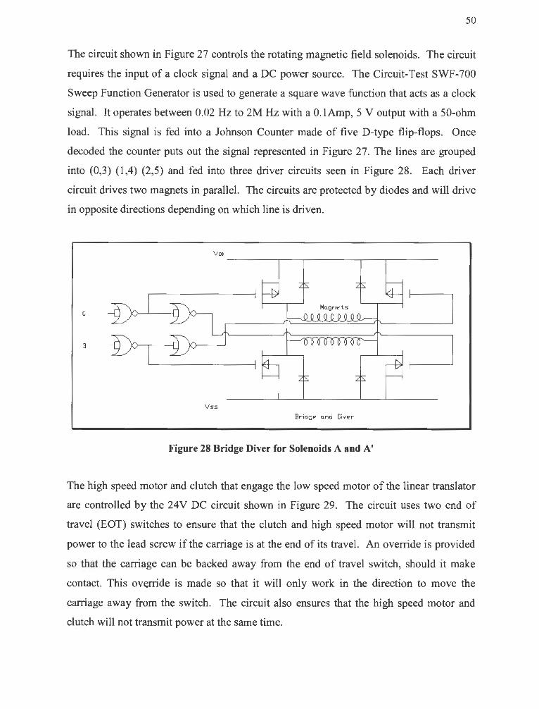
50
The circuit shown in Figure 27 controls the rotating magnetic field solenoids. The circuit
requires the input of a clock signal and a DC power source. The Circuit-Test SWF-700
Sweep Function Generator is used to generate a square wave function that acts as a clock
signal. It operates between 0.02 Hz to 2M Hz with a O. lAmp, 5 V output with a 50-ohm
load. This signal is fed into a Johnson Counter made of five D-type flip-flops. Once
decoded the counter puts out the signal represented in Figure 27. The lines are grouped
into (0,3) {l ,4) (2,5) and fed into three driver circuits seen in Figure 28. Each driver
circuit drives two magnets in parallel. The circuits are protected by diodes and will drive
in opposite directions depending on which line is driven.
V ua
0 Ha.gnets
3
Vss
Bridge crnd Diver
Figure 28 Bridge Diver for Solenoids A and A'
The high speed motor and clutch that engage the low speed motor of the linear translator
are controlled by the 24V DC circuit shown in Figure 29. The circuit uses two end of
travel (EOT) switches to ensure that the clutch and high speed motor will not transmit
power to the lead screw if the carriage is at the end of its travel. An override is provided
so that the carriage can be backed away from the end of travel switch, should it make
contact. This ov~rride is made so that it will only work in the direction to move the
carriage away from the switch. The circuit also ensures that the high speed motor and
clutch will not transmit power at the same time.

2
HflJI RD llJ1IJI DR~lJIJI :sYm;N
CLIDl INiMiMIKT 1-.nal
mr z
/'-~----.-~~~----{ ~ IA FlllE
N~ IPID NDllJlt
Figure 29 Control Circuit for Linear Translator
3. 7 Furnace Stands
51
The furnace stand is designed to hold the furnace, linear translator and motor driver
firmly while transmitting no vibration to the growth ampoule. The furnace is held at a
comfortable working height and allows full access to all components for ease of
operation. The stand and its sub-components are also adjustable to allow for the addition
of such things as cooling tail on the ampoule and acoustic wave mixing which may be
added for later experiments. Figure 30 illustrates the design of the stand and the position
of the mounting surfaces for the translator and motor driver. The motor mount is
vibration isolated for the base, which can be leveled by using four adjustable feet (not
shown).

52
FURNACE ~OUNlS 10 THIS FACE
~OUNllNG fACES or TRANLAlO~
TOP 'VI EW
~OUNTING r~CES or MOTlR DRIVE~
THM CRYSTAL GROWTH FRONT VIEW
Figure 30 Furnace Stand with Mounts for Motor Diver and Translator
53
4 Operating Procedure
4.1 Introduction
The purpose of this chapter is to give all future operators the knowledge, specific to this
furnace, which they will need to successfully grow crystals. This chapter is not intended
to give all the specifics on how to grow crystals by the THM, method and a strong
knowledge of the THM crystal growth technique will be needed to successfully use the
equipment described in this chapter. This chapter will describe the adjustment,
replacement and maintenance of all parts requiring such procedures as well as the
operation of all the components in the design.
4.2 Furnace Assembly
The furnace base cooling block and shell can be assembled and mounted on the stand
prior to the installation of all interior components. The solenoids can now be installed
and bolted to the bottom plate of the furnace. Care must be taken to mark the solenoid
leads so that the orientation of the field they generate will be known once the top plate is
in place and the solenoids cannot be seen. This can be done by marking all the leads that
come from the inside of the solenoids. Now the furnace liner, bottom and middle
marinite rings, and heater can be positioned. The heater leads should run to the cold side
of the insulation where they attach to the high temperature wire by means of two copper
couplings. This wire runs to a plug, which will be fixed to the top plate. Caution should
be taken to ensure that the solenoids are protected from contacting the coupling by the
sheets of mica. In order to align the remaining components two 1/8-inch steel rods can '
now be positioned in the two holes in the surface of the heater. Now the top marinite ring
and the fire brick can be put into position, the two steel rods assure the alignment of the
insulation so that the thermocouples can later be positioned into the furnace. In order to

54
facilitate the positioning of all the wiring to the top plate three sections of 10-32 threaded
rod should be screwed into the top surface of the furnace shell. The top plate can then
rest on nuts that are near the top of such rods and hold the top plate between l - l /2 and 2
inches above the furnace shell. Once all twelve solenoid wires, the heater, and ground
wire are connected, the three threaded rods can be removed and the top plate bolted into
place. The plug for the heater can then be bolted into place. The marinite alignment cap
should now be fixed on top of the top plate with the three alignment blocks. This cap
should be positioned so that the furnace liner is concentric with the cooling block and the
ampoule will slide smoothly through the furnace. The two steel rods can now be
removed and thermocouples positioned in the holes down the sides of the furnace liner
4.3 Furnace Operation
The furnace is controlled with the Omega CN3240 temperature controller. Prior to using
the controller, the constants that control the PID algorithm must be set. This can be done
automatically with the auto tuning function which is outlined in the operator's manual. In
order to achieve the most stable operation the tuning function should be run while under
as close to normal operating conditions as possible. This includes having the cooling
water running. The controller can now be set to ramp up to and hold the desired growth
temperature.
The cooling system has two basic components, a chiller and a pump. These are used to
circulate cooling water through copper piping that is wrapped around the outside of the
cooling block. The copper pipe should be held in place with the stainless steel sleeve to
help ensure good thermal contact. Thermal paste can also be used to decrease the thermal
resistance between the cooling block and the copper coil. The pump can be operated
independently of the chiller, it has an on off switch and speed controller. The chiller
ensures uniform cooling is supplied to the cooling block by holding the cooling fluid at a
constant temperature and needs only to be turned on and an appropriate temperature set.
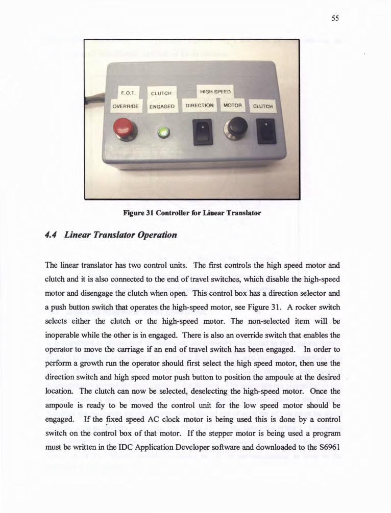
55
CLUTCH
ENGAGED
Figure 31 Controller for Linear Translator
4.4 Linear Translator Operation
The linear translator has two control units. The first controls the high speed motor and
clutch and it is also connected to the end of travel switches, which disable the high-speed
motor and disengage the clutch when open. This control box has a direction selector and
a push button switch that operates the high-speed motor, see Figure 31 . A rocker switch
selects either the clutch or the high-speed motor. The non-selected item will be
inoperable while the other is in engaged. There is also an override switch that enables the
operator to move the carriage if an end of travel switch has been engaged. In order to
perform a growth run the operator should first select the high speed motor, then use the
direction switch and high speed motor push button to position the ampoule at the desired
location. The clutch can now be selected, deselecting the high-speed motor. Once the
ampoule is ready to be moved the control unit for the low speed motor should be
engaged. If the fixed speed AC clock motor is being used this is done by a control
switch on the control box of that motor. If the stepper motor is being used a program
must be written in the IDC Application Developer software and downloaded to the 86961
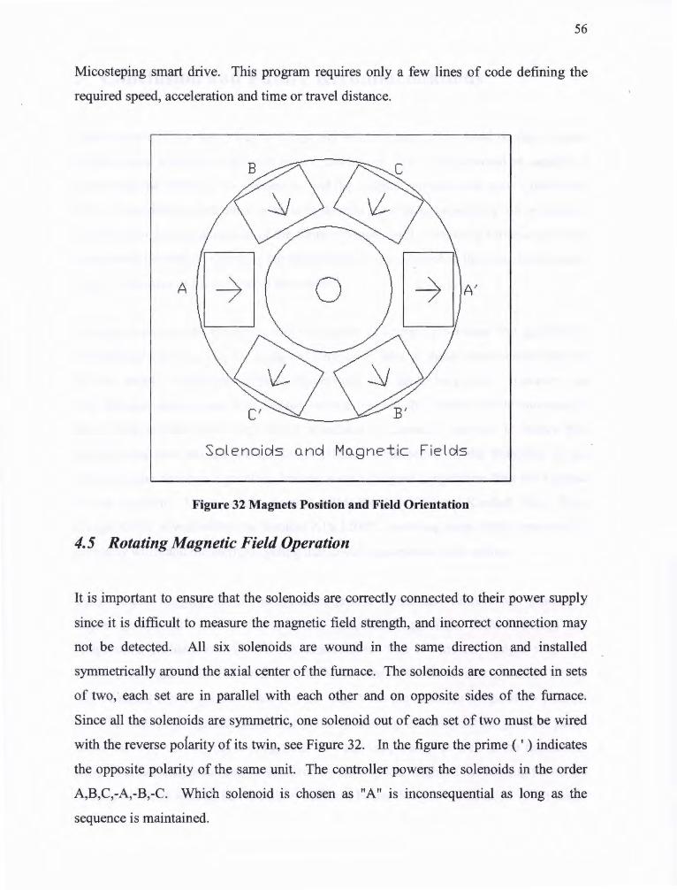
56
Micosteping smart drive. This program requires only a few lines of code defining the
required speed, acceleration and time or travel distance.
A
Solenoids o.nd Mo.gnetic Fie lds
Figure 32 Magnets Position and Field Orientation
4.5 Rotating Magnetic Field Operation
It is important to ensure that the solenoids are correctly connected to their power supply
since it is difficult to measure the magnetic field strength, and incorrect connection may
not be detected. All six solenoids are wound in the same direction and installed
symmetrically around the axial center of the furnace. The solenoids are connected in sets
of two, each set are in parallel with each other and on opposite sides of the furnace.
Since all the solenoids are symmetric, one solenoid out of each set of two must be wired
with the reverse poiarity of its twin, see Figure 32. In the figure the prime ( ' ) indicates
the opposite polarity of the same unit. The controller powers the solenoids in the order
A,B,C,-A,-B,-C. Which solenoid is chosen as "A" is inconsequential as long as the
sequence is maintained.

57
5 Conclusion and Future Recommendations
The objective of this thesis was to design and build a furnace that would be able to grow
crystals under a variety of different growth conditions. The furnace would be capable of
performing the necessary experiment to find the optimal parameters to grow CdZnTe by
THM. Since there is still much work to be done to see if these parameters can be found it
is difficult to assess the success of the furnace design. Still, comparing furnace operating
ranges with the desired operating parameters that where outlined in the first chapter gives
a good indication of the success of the design.
It was desired that the furnace would be capable of operating between 750 and 950°C.
The furnace has been run for sustained periods of time at these temperatures with no
adverse effects. Reliability at these temperatures has yet to be proven. However, the
only furnace components with limited service life are the heater and thermocouples.
These components can be replaced at scheduled maintenance intervals to ensure that
experimental runs are not wasted due to reliability problems. If the reliability of the
furnace heater becomes a problem, heating wires of higher temperature than the Kanthal
A 1 are available. These include Kanthal APM, Kanthal 1700 and Kanthal 1800. Even
though 950 °C is well within the Kenthal Al's l 200°C operating range higher temperature
wire may withstand the thermal cycling that lower temperature wires cannot.
Initial studies suggest that the temperature profile of the new furnace will produce a
higher growth rate due to its increased temperature gradient. THM-l design has
temperature gradient over 250 °C/cm, almost twice that of Amistar designs with 160
°C/cm (See Figure 20). The final test for the success of the furnace temperature profile
will be actual crystal growth, since it is not clear what the optimum temperature gradient
is. The furnace design addresses this point by making the temperature gradient partly
controllable by va'rying the cooling fluid flow and temperature as well as the furnace set
point. Further adaptation can be achieved by altering the height of the cooling fin on the
cooling block as well as incorporating different heater designs. Radiation is the major

58
means of heat transfer at temperatures the heater is operated at (between 850 and 950°C).
A heater design that focuses the radiant heat in a narrow band along the ampoule wall
could produce a narrower higher temperature zone and higher temperature gradients.
The linear translator effectively moves the ampoule at speeds ranging from above the
desired 10 mm/day to below the 1 mm/day. For added operating convenience a second
higher speed motor was also included in the design making it possible to quickly position
the carriage in the desired position. The stepper motor is simple to operate and it adjusts
to precise speeds. Since there is no known case of THM equipment being run with
stepper motors the translator was made so that other motor types could also be used, in
case the stepping action of the motor caused too much vibration. The gearing on the
motor was made to minimize such vibration, and it is felt that it will not be a problem.
The translator is designed to lower the ampoule from the bottom. This allows the
application of acoustic wave emitting devices to be attached to the bottom of the ampoule
as well as different cooling apparatus.
The field generated by the six solenoids was measured individually and ranged in value
between 1.3 and 1.4 mT at a distance of about 3.5 inches from the face of the solenoid
with a l 2.5V power supply. With the solenoids operating in pairs so that their field
strength is added this gives a total field of about 2.7 mT. It is incorrect to assume that
the full field will be generated by the solenoids operating at higher frequencies since
inductance will reduce the current in each coil. By observing the voltage across each
solenoid with an oscilloscope while the magnets ran at different frequencies, the spike
resulting from the inductance of the solenoids was observed to occupy approximately
50% of the one time in each cycle at l 50Hz. This means that at 150Hz 50% of the time
on each solenoid is used to overcome impedance and arrive at full current. At higher
frequency this amount increases. For this reason it was felt that 150Hz should be a
maximum operating frequency of the magnets. If a method of measuring the field at . higher frequencies could be found it would be possible to assess the magnets effect more
accurately. This may allow higher frequencies to be used. Higher frequencies could also
be achieved by increasing the voltage to the magnets or double winding them.

59
The furnace was designed so that future experiments could be performed within a l .OT
static magnetic field. In order to achieve this the furnace diameter was kept as small as
possible and no hookups are protruding from the side of the furnace. Since the fixed
magnet will operate at cryogenic temperatures it is important that the furnace wall
temperatures not be to hot, leading to to much execs excessive work by the cryogenic
refrigeration unit. The solenoids and furnace were run for extended periods while warped
in a layer of insulation to simulate the reduced convection that will result from the fixed
magnet. After over six hours of operation the furnace shell was below 40°C in call cases.
At the time of publication the design and construction of a superconducting 1.0 T magnet
under way. The inside bore of the magnet is 13.2in. allowing 1/4 of an inch clearance.
The furnace was also made with non-magnetic material. Prior to operation with the I .OT
magnet is the furnace should be converted to DC operation. This can be done with the
existing controller by simply switching the power to the solid state relay from a 11 OV
60Hz to a rectified 11 OV DC power supply.
60
6 BIBLIOGRAPHY
1 Benz K.W., Muller G. GaSd and InSd Crystals Grown by Vertical and Horizontal Travelling Heater method. Journal of Crystal Growth 1979 vol.46 p35-42
2 Handbook of Crystal Growth, D,T.J. Hurle North-Holland 1994 Amsterdam 2a P.654-655
3 Crystal Growth: an Introduction, W. Bardsly, D.T.J. Hurle and J.B. Mullin, North-Holland Publishing LTD. 1973
4 Crystal Pulling from the Melt, Donald T.J. Huie Spring-Verleg 1993New York p.12-14 Discussions with Brian Lent researcher University of Victoria, Victoria B.C. Canada Jan. to April 2001
5 Senchenkov A.S., Barmin I.V., Tomson A.S., Krapukhin V.V. Seedless THM growth of CdxHgl-xTe single crystals within rotating magnetic Field. Journal of Crystal Growth 1999 vol. 197 p. 553-556
6 Dinger R. J. , Fowler I. L., The inclusions in CdTe Grown.from a slowly cooled Te Solution and by the Traveling Heater Method. Revue of Applied Physics Feb. 1977 page 135
7 Kanai H., Kimura M., Tanaka A., Sukegawa T. , "LPE Growth of GaAs By Yo-Yo Solute Feed Method' p. 229-234
8 Sukegawa T., Kimura M ., Tanaka, "Gravity Effect on Dissolution and Growth of Silicon in In-Si System" Journal of Crystal Growth 99 p46-52 1988
9 Kimura M, Tanaka A., Sukegawa T., Gravity Effect on Solute Transport in Dissolution and Growth of Silica" Journal of Crystal Growth, 00 pl295-1299 1990
1°Kimura M., Qin Z., Dost S., "A Solid Liquid Diffusion Model for Growth and Dissolution of Turnery Alloys by LPE", Journal of Crystal Growth, 158 p. 231-240 1996
11 Dost S., Qin Z., Kimura M., "A Model for Convective Mass Transport in Liquid Phase Epitaxail Growth of Semiconductors" International Journal of Heat and Mass Transfer, 40 (13) 1997
12 Senchenkov A.S., Barmin l.V., Tomson A.S., Krapukhin V.V. Seedless THM growth of CdxHgl-xTe
13 D.T.J. Hurle, R.W . Series , Hand Book Of Crystal Growth . Vol 2a Elsevier Science, Amsterdam, 1994, pp. 259-285
14 Dost S. , Sheibani H., Liquid Phase Electroepitaxial Growth of Ternary Single Crystal Under Magnetic Field. Advances in Computational Engineering & Science. Tech Science Press vol. I , 2000

61
15 Mobner R., Gerberth G., Buoyant Melt Flows Under the Influence of Steady and Rotating Magnetic Fields. Journal of Crystal Growth 1999 vol. 197 p. 341-354
16 Microgravity News 1997 NASA News Releas No.97-109 National Aeronautic and Space Administration www .larc.nasa.gov
17 Senchenkov A.S., Barmin I.V., Tomson A.S ., K.rapukhin V.V. Seedless THM growth of CdxHgl-xTe
18 Salk M,Fiederle M., Benz K.W., Senchenkov A.S., Egorov A.V., CdTe and CdTeSe Crystals Grown by Traveling Heater Method using a Rotating Magnetic Field, Journal of Crystal Growth 1994 vol.138 pl61-167
19Ghadder C.K.,Lee C.K., Motakef S., Gillies D.C., Numerical Simulation of THM Growth of CdTe in the Presence of Rotating Magnetic Field, Journal of Crystal Growth 1999 vol. 205 P .97-111
20Senchenkov A.S., Barmin I.V., Tomson A.S., K.rapukhin V.V. Seedless THM growth of CdxHgl-xTe
21 Dinger R.J. , Fowler I.L. Te Inclutions in CdTe Grown from a Slowly Cooled Te Solution and by the Traveling Solvent Method. Revue du Physique Appliquee. 1977 p.135
22 Benz K.W., Muller G., GaSb and InSb Crystals growen by Vertical and Horizontal Traveling Heater Method. Journal of Crystal Growth 1979
23 Benz K.W. Bischopink G., THM Growth and Properties of JnGaP Journal of Crystal Growth 1979 p245-253
24 Benz K.W., Bischopink G. , Growth of AlGaSb Bulk Material from Metallic Solution Journal of Crystal Growth 1991 p465-472
25 Sickinger P., Hofmann P. , Kemmerle E., Wulf E., Senchenkov A.S., Egorov A.V. , Barmin I.V., Matiouklin D.G. , Slak M., Benz K.W., Mission Support for Crystal Growth Experiments on Russian Unmanned Carries Proceeding Villth European Symposium on Materila and Fluid Science in Microgravity Brussels Belgim April 1992
26 Barmin I.V., SenchenokovA.S., Technological Equipment of SPLAV Technical Center for Producing Material in Space. Some Results of the Experiments on Crystal growth. Microgravity Q. Vol.3 pp. 233-239 1993
27 Slak M. , Lexom B., Benz K.W., Matioukhim D.G., Gelgat Y.M., Sorkin M.S., Senchen.kov A.S., Egorov A.V.,,Barmin I.V., Stickinger P ., HofmannP., and KlettR.,CdTe Crystal Growth in the Soviet Facility ZONA 4 Microgravity Scvience and Technology Hanser Publishers Munich 1993

62
28 Salk M,Fiederle M., Benz K.W., Senchenkov A.S., Egorov A.V., CdTe and CdTeSe Crystals Grown by Traveling Heater Method using a Rotating Magnetic Field, Journal of Crystal Growth 1994 vol.138 pl61-167
29 Senchenkov A.s., Barmin l.V., Tomson A.s., Krapukhin V.V., Seedles THM Growth of CdHgTe Single Crystals Within Rotating Magnetic Field Journal of Crystal Growth 1998
3° Fiederle M., Feltgen T., Meinhadt J., Rogalla M., Benz K. W., State of the Art (CdZn)Te as Gamma Detectors. Journal of Crystal Growth 1999 p. 635-640
31 Paulus M.J., Sari-Sarraf H., Gleason S.S., Bobrek M., Hicks J.S., Johnson D.K., Behe!J.K., ThompsonL.H. , Allen W.C., A New X-Ray Computed Tomography System for Laboratory Mouse Imaging Transactions on Nuclear Science June 1999
32 Bicron Crystal Products 750 S. 32nd. Street Washougal, WA 98671 www.bicronne. com/ bicronmed/ newdir.htm
33 Technology Focus Bulletion of Defence Reasearch & Development Organization Vol. 7 No. I Feb.1999 ISSN: 0971-4413 www.nic.in/techfocus/feb99/cdzn.htm
34 Bicron Crystal Products 750 S. 32nd. Street Washougal, WA 98671 www. bicronne. com/ bicronmed/ newdir.htm
35Paulus M.J., Sari-Sarraf H., Gleason S.S., Bobrek M., Hicks J.S., Johnson D.K., BehelJ.K., ThompsonL.H., Allen W.C., A New X-Ray Computed Tomography System for Laboratory Mouse Imaging Transactions on Nuclear Science June 1999
36 Scheiber C. New Developments in Clinical Applications of CdTe and CdZnTe Detectors. Nuclear Instruments and Methods in Physics Research 1996 p385 391
37 Society Of Nuclear Medicine 1850 Samuel Morse Dr. Reston, VA 20190 www .snm. org/nuclear /xrays.html
38 http://southflorida.sun-sentinel .com/careers/vitalsigns/partfolder/X 1 Onmdtech.htm
39 www.ibl.gov/Science-Articles/ Archive/nuclear-med-history .html
40 Bicron Crystal Products 750 S. 32nd. Street Washougal, WA 98671 http:// www. bicron. com/oilweb /character.htm
41 Steigerwald B. NASA News Releas No.97-109 National Aeronautic and Space Administration www.gsfc.nasa.gov/news-release/releases/ 1997 /97-1 09 .htm
42 Lavietes A.D., McQuaid J.H., Paulus T.J., Preliminary Uranium Analysis Results using Cadium Zince Tel/u~ide Detectors Nuclear Instruments and Methods in Physics Research 1996 p 406-409
43Steigerwald B. NASA News Releas No.97-109 National Aeronautic and Space Administration www .gsfc.nasa.gov/news-release/releases/ 1997 /97- 109 .htm

63
44 Lingzhi Li Growth of CdTe/CdZnTe Single Crystals by the Vertical Gradient Freezing Method Submitted to the Department of Mechanical Enginering University of Victoria Victoria Canada, 1999
45 Adachi A., Journal of Applied Physics (USA) Vol.53 1982 p.8775-8792
46 Adir Bar-Lev Semiconductors and Electronoc Devices 2nd EditionPrentice-Hall, Inc. 1984
47 www.ii-vi.com/pages/pod-ev-materials.html
48Digirad 9350 Trade Place San Diego, CA 92126-6334 www.digirad.com
49 Mermon H. Schieber M. James R.B., Yang N., Antolok A.J., Morse d., Komer V., Goorsky M.S., Yoon H., Toney J., Schlesinger T.E., Comparison Between Cadmium Zinc Telluride Crystals Grown in Russia and in the Ukraine. Material Science Society Symposium Vol.487 1998
50 http://users.zoomintemet.net/-kcc/index.html
51 Lent Brian, (Crystal Growth Researcher) Interview,. University of Victoria, Victoria BC Canada. Jan. to April 2001
52 www l .ansys.com/
53ANSTYS User's Manual Revision 5.0 Volume 1 DN-R300:50- l Page.10.2 or http:// wwwl. ansys. com/ customer/ content/documentation/56/Hlp_C_SOLCONTROL.html
~aylored Industries, Inc. is a privately held company, established in 1965 and based in Cheswick, Pennsylvania, USA Salers Information http:// www.tayloredindustries. corn/ thermprodmap. htm
55San Diego Plastice Inc. 2220 McKineley Av. National City Ca. Sales Information www .sdplastics.com/phenolic.html
OTHER MATERIALS SITED
Handbook of Crystal Growth Basic Techniques D.T.J.Hurle North-Holland 1994
Art and Science of Growing Crystals J.J. Gilman. John Wiley & Sons, 1963
Crystal Growth an Introduction P. Hartman Noth-Holland 1973
Fundamentals of Cry~tal Growth F . Rosenberger, Springer-Velag 1979
Discussions with Brian Lent researcher University of Victoria, Victoria B.C. Canada Jan. to April 2001
Art and Science of Growing Crystals J.J. Gilman. John Wiley & sons, 1963

64
Crystal Growth an Introduction P. Hartman Noth-Holland 1973
Fundamentals of Crystal Growth F. Rosenberger, Springer-Velag 1979
Senchenkov A.S., Bannin l.V., Tomson A.S., Krapukhin V.V., Seddles THM growth of CdHgTe single crystals within Rotating Magnetic Field. Journal of Crystal Growth 1998
Meric, R.A. Dost, S. Lent B. Redden R.F. A numerical Simulation Model for the Growth of GalnSb by the Traveling Heater Method. Journal of Applied Electromagnetic and Mechanics 1999
Brykiewics T., Liquid Phase Electroepitaxy of Semiconductor Compounds Crystal Growth Department of Material Science and Engineering , Massachusetts Institute of Teclmology, Cambridge Mass. 1986
Bryskiewcz T., Bugajski M., Lagowski j., Gates H.C., Growth and Characterization of high Quality PLEE GaAsd Bulle Crystals, Journal of Crystal Growth p.136-141 , 1987
Bryskiewcz T., Laferriere A., Growth of Alloy Substrates by Liquied Phase Electroepitaxy;Theoretical Conserations, Journal of Crystal Growth p.429-442, 1993
Lingzhi Li Growth of CdTe/CdZnTe Single Crystals by the Vertical Gradient Freezing Method Thesis submitted to Department of Mechanical Engineering University of Victoria 1999

65
APENDIX A Source Code for Ansys Models

!-----------------------------------------------------------------------------------------------------------------------------
!ANSYS command file for 2D Thermal Analysis of Amistar THM Design ! FINISH /CLEAR.NOST ART
/title, THM Amistar Prototype Furnace
!End and Clear all Existing Models
!----------------------------------------------------------------------------------------------------------------------------/UNITS,si /PREP7
RECTNG,-.002,0,.064,-.064 RECTNG,0,.056,.038,.064 RECTNG,.020,.056,.012,.038 RECTNG,0,.056,0,.012 RECTNG,0,.056,0,-.0 l 0 RECTNG,0,.034,-.0 I 0,-.064
UIMP,2,DENS,, ,2700, UIMP,2,KXX, , ,0.78, UIMP,2,C, , ,.84, UIMP,2,HF,, ,00, !
UIMP,5,DENS,, ,2787, UIMP,5,KXX,, ,164, UIMP,5,C,, ,.883 , UIMP,5,HF, , ,00, ! !
!Setting SI Units
!Defining Areas
!Furnace Liner 2, I 0 !Top Insulation 4,9 !Middle Insulation 4,9 !Bottom Insulation 4,9 !Bass Plate 3,7 !Cooling Block 3,7
Properties of material 2 (quatrs liner)
!Density !Thermal Conductivity !Specific Heat !Convective Film Coefficient
Properties of material 5 (cooling block "Al")
!Density !Thermal Conductivity !Specific Heat !Convective Film Coefficient
Properties of material 3 (fire brick, "lnsalcor")
MPTEMP, 1,300,533.15,810.97, 1088.71,1366.48,1644.26
MPDARA,KXX,3, 1,0.8,0.8955 ,0.9118, 1.0258, l .2375, 1.498,
UIMP,3,DENS, , ,2707, UIMP,3,C,, ,.896, UIMP,3,HF,, ,2.64, ! ! ET,2,PLANE77 ET,l,PLANE55 ! A GLUE, l ,2,3,4,5 ,6
ESIZE,0.002,0,
!Density !Specific Heat !Convective Film Coefficient
Selecting Element Type
!Gluing Areas
Setting Mesh Size
Setting Material Properties and Meshing
66
ASEL,, , ,12 AA IT,2, ,2,0 Amesh,all Asel,all
ASEL,,, ,8 ASEL,A,, , 11 AAIT,5, ,2,0 Amesh,all Asel,all ! ASEL,,, ,9 ASEL, A, , , I 0 ASEL,A,, ,7 AAIT,3, ,2,0 Amesh,all Asel,all
/SOLU
NSUBST,2,5,2 AUTOTS,ON
DL,38, ,TEMP, 1170,1 DL,32, ,TEMP, 1170,1 DL,33, ,TEMP,1170,1 DL,12, ,TEMP,1170,l ! DL,22, ,TEMP,303,1 ! SOLVE
FINISH
!Selecting Liner !Setting, mat.#, ,eliment#.,COORDINATE# !Meshing volume !Unslecting!
!Selecting Cooling Block
!Setting, mat.#, ,eliment#.,COORDINATE# !Meshing volume !Unslecting!
!Selecting Insulation
!Setting, mat.#, ,eliment#.,COORDINATE# !Meshing volume !Unslecting!
!Fixing temp. Around Heater
!Fixing temp. on outside of Cooling Block
Solving Model
! !-----------------------------------------------------------------------------------------------------------------------------! /POSTI SET,LAST PLNSOL,TEMP, ,0,
Showing Results
!-----------------------------------------------------------------------------------------------------------------------------
FINISH /CLEAR.NOST ART
!End and Clear all Existing Models
!ANSYS Command File for 20 Thermal Analysis ofTHM Furnace (with Sloping cooling block) ! . /title, THM Sloping Cooling Block Design ! /UNITS,si !SI Units !-----------------------------------------------------------------------------------------------------------------------------
/PREP7
67

RECTNG,0,.0020,0,.048 RECTNG,.002,.058,.024,.048 RECTNG,.020,.058,0,.024 RECTNG,.024,.058,0,-.024 LSTR,1 ,16 LSTR,1,13 AL,16,18,17 RECTNG,0,.036,-.034,-.06 LSTR,13,19 LSTR,1 ,20 AL,24,18 ,23,21
UIMP,2,DENS,, ,2700, UIMP,2,KXX,, ,0.78, UIMP,2,C, , ,.84, UIMP,2,HF,, ,00, !
UIMP,5,DENS,, ,2787, UIMP,5,KXX,, ,164, UIMP,5,C,, ,.883, UIMP,5,HF,, ,00, !
Defining Areas
!Furnace Liner 2,10 !Top Insulation 4,9 !Middle Insulation 4,9 !Bottom Insulation 4,9 !lines for insulation !lines for insulation Make Areas with Lines !Cooling Block 3,7! !lines for insulation !lines for insulation Make Areas with Lines
Properties of material 2 ( quatrs liner)
!Density !Thermal Conductivity !Specific Heat !Convective Film Coefficient
Properties of material 5 (cooling block "Al")
!Density !Thermal Conductivity !Specific Heat !Convective Film Coefficient
Properties of material 3 (fire brick, "lnsalcor")
MPTEMP,1 ,300,533.15,810.97,1088.71,1366.48, 1644.26
MPDARA,KXX,3, l ,0.8,0.8955,0.9118, 1.0258, 1.2375, 1.498, ! UIMP,3,DENS,, ,2707, UIMP,3,C,, ,.896, UIMP,3,HF,, ,2.64, !
ET,l,PLANE55 ET,2,PLANE77
AGLUE,l ,2,3,4,5,6,7
ESIZE,0.002,0,
ASEL,, , ,9 AA TI,2, ,2,0 AMESH,all ASEL,all ! ASEL,,, ,7
!Density !Specific Heat !Convective Film Coefficient
!Selecting Element Type
Gluing Areas
Setting Mesh Size
Matching material Properties and Areas and Meshing
!Selecting Liner !Setting, mat.#, ,eliment#. , Coordinate# !Meshing volume !Unslecting!
!Selecting Cooling Block Triangle
68
AATI,5, ,2,0 Amesh,all Asel,all
ASEL,,, ,10 AA TI,3, ,2,0 Amesh,all Asel,all
ASEL,,, ,11 ASEL,A,, ,12 ASEL,A,, ,8 AATI,3, ,2,0 Amesh,all Asel,all
MSHK.EY,l ASEL, ,, ,6 AA TI,5, ,2,0 Amesh,all Asel,all !
!Setting, mat.#, ,eliment#., Coordinate# !Meshing volume !Unslecting!
!Selecting triangle part of insulation !Setting, mat.#, ,eliment#., Coordinate# !Meshing volume !Unslecting!
!Selecting Insulation
!Setting, mat.#, ,eliment#.,COORDINATE# !Meshing volume !Unslecting!
Use mapped meshing !Selecting Cooling Block !Setting, mat.#, ,eliment#.,COORDINATE# !Meshing volume !Unslecting!
!-----------------------------------------------------------------------------------------------------------------------------
/SOLU
DL,27, ,TEMP, 1170,1 DL,32, ,TEMP,1170,1 DL,29, ,TEMP, 1170,1 DL,12, ,TEMP, 1170,1
DL,20, ,TEMP,303,1
SOLVE
FINISH
!Fixing temp. Around Heater
!Fixing temp. on outside of Cooling Block
! Solve Model
! !-----------------------------------------------------------------------------------------------------------------------------
/POST! SET,LAST PLNSOL,TEMP, ,0,
Display Results!
'-----------------------------------------------------------------------------------------------------------------------------. ' ! ANSYS Command File for 2D Thermal Analysis ofTHM-IFurnace (extended cooling block) ! ! /title, THM Extended Cooling Block Design !
69
/UNITS,si !
!SI Units
!-----------------------------------------------------------------------------------------------------------------------------
/PREP?
RECTNG,0,.002,0,.050 RECTNG,.002,.0 I 0,0,.002 RECTNG ,.0 I 0,.058,-.022,.002 RECTNG,.022, .058,.002,.026 RECTNG,.002,.058,.026,.050
RECTNG,0,.002,0,-.008 RECTNG,0,.0 I 0,-.008,-.022 RECTNG,0,.058,-.022,-.032 RECTNG,0,.036,-.032,-.060 ! AGLUE,1,2,3,4,5,6,7,8,9 LSTR,22,27 LSTR,2,27 LSTR,6,27 AL,2,39,57 AL,38,52,2
AGLUE, l ,2, 11 ,12,13,14,15,17,18 l
UIMP,2,DENS, , ,2700, UIMP,2,KXX,, ,0 .78, UIMP,2,C,, ,.84, UIMP,2,HF, , ,00, !
UIMP,5,DENS,, ,2787, UIMP,5,KXX, , ,164, UIMP,5,C, , ,.883, UIMP,5,HF,, ,00,
Defining Areas
!Furnace Liner 2, 10 !Insulation Small Block4,9 !Bottom Insulation 4,9 !Middle Insulation 4,9 !Top Insulation 4,9
!Cooling Block top very small !Cooling Block middle small !Bottom Plate -long !Cooling Block big bottom
!Glue Areas !lines for insulation !lines for insulation !lines for insulation !Make area with lines !Make areas with lines
!Gluing Areas
Properties of material 2 (quartz liner)
!Density !Thermal Conductivity !Specific Heat !Convective Film Coefficient
Properties of material 5 (cooling block "Al")
!Density !Thermal Conductivity !Specific Heat !Convective Film Coefficient
Properties of material 3 (fire brick, "Insalcor")
MPTEMP,1,300,533.15,810.97,1088.71,1366.48, 1644.26
MPDARA,KXX,3, 1,0.8 ,0.8955 ,0.9118, 1.0258, 1.2375, 1.498,
UIMP,3,DENS, , ,2707, . UIMP,3,C, , ,.896, UIMP,3,HF,, ,2.64, l
ET,3,PLANE55
!Density !Specific Heat !Convective Film Coefficient
Selecting Element Type
70

ET,2,PLANE77
ESIZE,0.001,0,
ASEL,,, ,16 AATT,2, ,2,0 AMESH,all ASEL,all
ASEL,,,, 1 ASEL,A, , , 11 ASEL,A,, ,12 ASEL,A, , , 14 ASEL,A, , , 18 AA TT,3, ,2,0 Amesh,all Asel,all ! ASEL,, , ,2 ASEL, A, , , 10 ASEL,A, , , 13 ASEL,A, , , 15 ASEL,A, , , 17 AATT,5, ,2,0 Amesh,all Asel,all
Setting Mesh Size
!Selecting Liner !Setting, mat.#, ,eliment#., Coordinate# !Meshing volume !Unslecting!
!Selecting Insulation
!Setting, mat.#, ,eliment#., Coordinate# !Meshing volume !Unslecting!
!Selecting Cooling Block
!Setting, mat.#, ,eliment#., Coordinate# !Meshing volume !Unslecting!
!-----------------------------------------------------------------------------------------------------------------------------
/SOLU
AUTOTS,ON
DL,7, ,TEMP,1170,1 DL,16, ,TEMP,1170,1 DL,48, ,TEMP, 1170, 1 DL,53 , ,TEMP,1170,1 DL,58, ,TEMP,1170,1
DL,34, ,TEMP,303,1
SOLVE
FINlSH
!Fixing temp. Around Heater
!Fixing temp. on outside of Cooling Block
Solving
! !-----------------------------------------------------------------------------------------------------------------------------
/POST! SET.LAST PLNSOL,TEMP, ,0,
Displaying Results
71

72
APENDIX B Engineering Drawings

I . 3 7 5
I . 7 50
3.500 I I
3. 7 50
.250 1- 4.25 -1 ) EJ I T ¢. 191 THRU 4PL
4.00
¢. 19 THRU 2 PL ¢. 19 THRU 2 PL
1.125 IEJ Dal
. xx ±. 0 I
. xxx±.005 UNLESS OTHERWISE STATED REMOVE ALL SHARP CORNERS AND DEBURR
IE3 2.125 c=-1
i-s---- 3 . I 2 5 °"' I
MUST BE MADE FROM PLATE PROJECT
CRYSTAL GROWTH THM PART UPRIGHT MOVING PLATE
MECHANICAL ENGINNERING UVIC
1/4 in. THICK I QTY DRN BY: M. CROWLE SCALE: I REV: DATE: APR IL 3 IOI APPROVED BY:
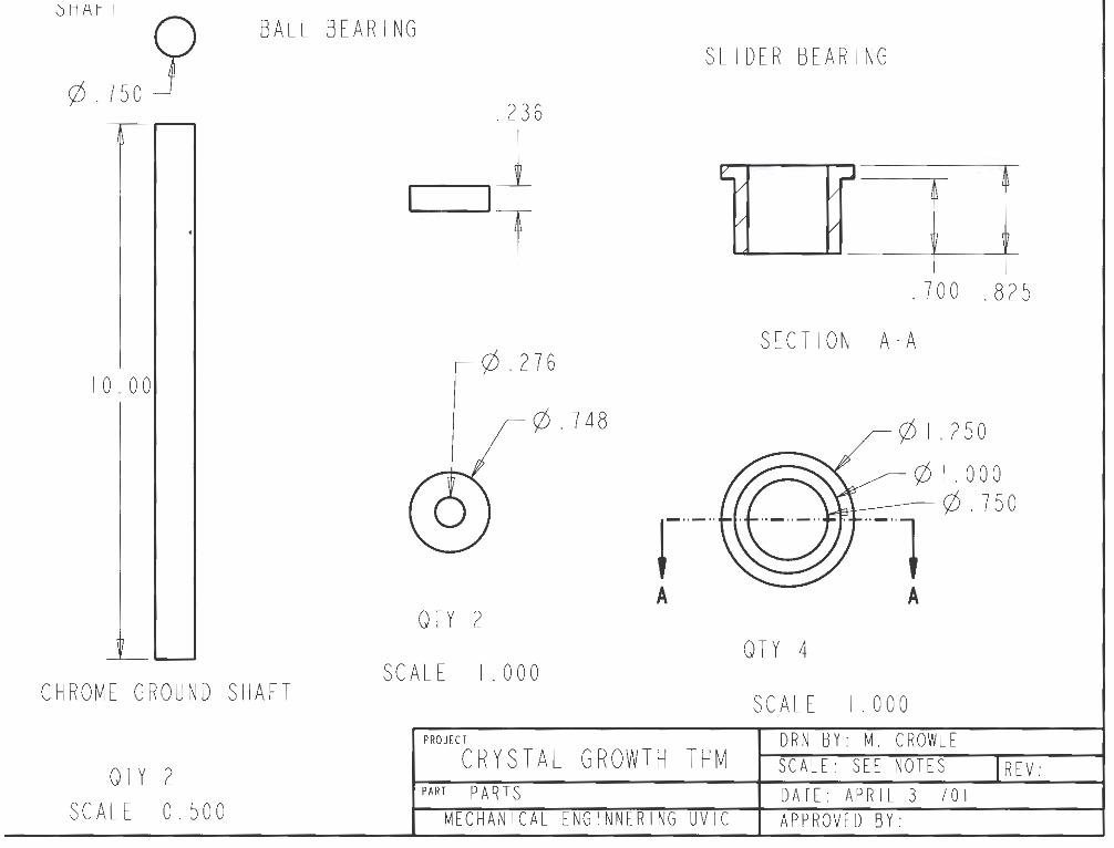
0HfH I BALL BEARING
¢. 750 y SLIDER BEARING
10.00
CHROME GROUND SHAFT
QTY 2 SCALE 0.500
.236
-1 -1 l 1
¢. 276
¢. 748
r-· A
QTY 2
SCALE I . 000
PROJECT
CRYSTAL GROW TH THM PART p ART s
MECHANICA L ENGINNERING UVIC
.700 .825
SECTION A-A
¢I. 250
¢I. 000 ¢. 750
A
QTY 4
SCALE I . 000 DRN BY: M. CROWLE SCALE: SE E NOTES REV: DATE: APRI L 3 IOI APPROVED BY:
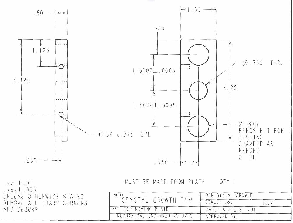
.50 IEc:-1
I . I 2 5
3. I 2 5
. 250 l~I
. xx ±. 0 I
. xx x±. 0 0 5 UNLESS OTHERWISE REMOVE ALL SHARP AND DEBURR
STATED CORNERS
I . 50 E>I
. 625
I . 5 0 0 0± . 0 0 0 5
I . 5 0 0 0± . 0 0 0 5
10 - 32 x.375 2PL
.750 IE3 e;..I
MUST BE MAD E FROM PLATE
PROJECT
CRYSTAL GROWTH THM PART TOP MOVING PLATE
MECHANICAL ENGINNER ING UVIC
¢. 750 THRU
4.25
L..:3 1 I ¢.875
QTY I
PRESS FIT FOR BUSHING CHAMFER AS NEEDED 2 PL
DRN BY: M. CROWLE SCALE: .85 REV: DATE: APRIL 6 /01 APPROVED BY:

. 50 Doi
.625 II 501
10-32 x.375 ZPL I . I 2 5
3. I 2 5
. 250 _j . xx ±. 0 I . xx x± . 0 0 5 UNLESS OTHERWISE STATED REMOVE ALL SHARP CORNERS AND DEBURR
I
1.5000±.0005'"---.J
I . 5 0 0 0± . 0 0 0 5
. 750 IEJ DI
MUST BE MADE FROM PLATE
PROJECT
CRYSTAL GROWTH THM PART BOTTOM MOVING PLATE
MECHANICAL ENGINNERING UVIC
4.25
¢. 875 PRESS FIT FOR BUSHING CHAMFER AS NEEDED 2 PL
5/8-18 THRU
I REQUIRED
DRN BY: M. CROWLE SCALE : 0.85 IREV: DATE: APRIL 3 /01 APPROVED BY:
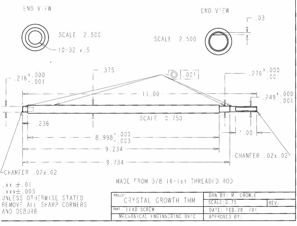
END VIEW
.276+.000 - .001
SCALE 2.500
10-32 x.5
.375
END VIEW
SCALE 2.500
.03
.276+.000 -.001
IEJ ~~..........-:= 11.00 ~ I c-1 .249+.000 -.001
SCALE 0.750 .236
8.998+.000 -=:;t--------- - . 0 0 3 - -9.234 ----~
I . 0 0 p
9. 734 -------~J CHANFER . 02 x. 02
CHAMFER . 02x. 02
. xx ±. 0 I
. xx x±. 0 0 5 UNLESS OTHERWISE STATED REMOVE ALL SHARP CORNERS AND DEBURR
MADE FROM 3/ 8- 16 - Is t THREADED ROD
PROJECT DRN BY: M. CROWLE CRYSTAL GROWTH THM SCALE:O. 75 REV:
PART LEAD SCREW DATE: FEB.28 /01 ME CHAN I CAL ENG TNN[R l NG UV IC APPROVED BY:
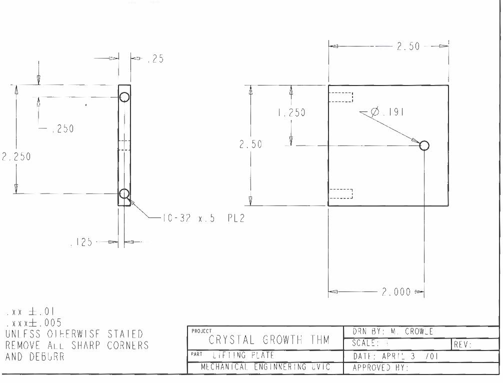
.250
2.250
. xx ±. 0 I
.xxx±.005
1125
I 2 5 j t-E:I <:J,i-
UNLESS OTHERWISE STATED REMOVE ALL SHARP CORN.ERS AND DEBURR
t-:3----- 2 . 5 0 c:-1
------, I ______ J
I . 2 50
2. 50
------, I ______ .J
10-32 x.5 PL2
l-E9--- 2. 000
PROJ£CT DRN BY: M. CROWLE CRYSTAL GROWTH THM SCALE: I IREV:
PART LI FT I NG PLATE DATE: APRIL 3 IOI MECHANICAL ENG INNERING UV IC APPROVED BY:

I
9.00 9. 7 50
h
5.00
y
1.00 .~)0 w
ll
h I
I'"" 8.00 4 .19 1 PL4 I -0 ~
-c
h
~l L.19 I\_ R. 093
IE e>I I I . 0 0
"'
"'
1.25 IE D
MUST BE MADE FROM 1/2 I QTY
xx ±. 0 I . xxx±. 005
1n. PLATE l-a-----2.750e--,
E3----- 5. 250 e
6 . 7 5 E>j
PROJECT DRN BY: M. CROWLE
10.00
UNLESS OTHERWISE STATED REMOVE ALL SHARP CORNERS AND DEBURR
CRYSTAL GROWTH THM SCALE: 0.5 IREV: PART BACK PLATE DATE: APLRIL 3 /01
MECHANICAL ENGINNERING UVIC APPROVED BY:

.50 C3al
.250 C3a l
. 7480+.0005 -.0000
.236+.000 -.001 -Dal
. 2 5 0 ______j
-, ,--' I I I I , __
.625
3.625
.625 I . 7 5 . 250 ----i~
.875
¢. 625
I. 5000±. 0005 3.375
4.25
I . 5 0 0 0± . 0 0 0 5
¢. 750~: ~~62PL
10-32 THRU 2PL 10-32 x.375 2PL
. xx ±. 0 I
.xxx±.005 UNLESS OTHERWISE STATED REMOVE ALL SHARP CORNERS AND DEBURR
IEJ D-1 .875
MUST BE MADE FROM PLA TE
PROJECT
CRYSTAL GROWTH THM PART BOTTOM BEAR I NG MOUNT
MECHANICA L ENGINNERING UVIC
.250 E3ol
REQUIRED
DRN BY: M. CROWLE SCALE: 0.75 IREV: DATE: APRIL 4 IOI APPROVED BY:

I . 2 5 e>1
I
r"""
. 75 ' --
" ~
~ --- -,.__
L ______ _ .38
! TOLERENCES . X± . 015 . XX± . 0 I . XXX± . 005 UNLESS OTHERWISE SPECIFIED REMOVE ALL SHARP CORNERS AND BEBURR
PROJ[CI
PARI
' f I . 2
I . 0 0 .255
0
~ ~
R2.000
MADE FROM ALUMINUM PLATE
CRYSTAL GROWTH THM REV: ORN BY: M. CROWLE SCALE: 1.5
TOP BRACE DATE: MAY 6 IOI QTY: 3 MECHANICAl ENGINNERING UVIC APPROVED BY:

4. 6 6
3. 7 5 I
3. 7 3 .94
.375
TOP PLATE
4.84 IE :1: -, 4.84 1\
213
: l""-1 =-~ IE3 ... I : 1\213
I ~ I " I ~ ~ f ! I I . I 0
10-32 3PL ON 6.00 BHD
¢.19 12PL 12.30 BHD
¢3.50 CENTARED
¢ 12. 70
10-32 4PL I
2.90 .375
3. 75 I
3. 7 3
4.66
TOLERENCES . X± . 015 . XX± . 0 I . XXX± . 005
.94
UNLESS OTHERWISE SPECIFIED REMOVE ALL SHARP CORNERS AND BEBURR
.785 I I r>I
I I - . 7 85 3.0 1- 3.0
4.00 - 4.00
.80
</Jl.50 6PL ON 10.00 BHD
.257 4PL
R . I 8
¢.375 6PL ON I I . 50 BHD
MATL ALUM 6061 3/8 PLATE
PROJECT CRYSTAL GROWTH THM I ~~~L~~: 0. ~5 CROWLE I REV: I PART TOP PLATE DAT[: MAY 6 /01 I OTY: I
MECHANICAL ENGINNERING UVIC APPROVED BY:
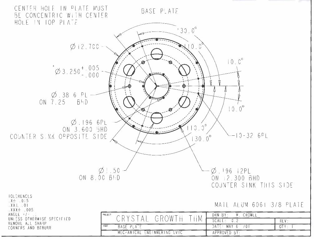
CENTER HOLE IN PLATE MUST BE CONCENTRIC WITH CENTER HOLE IN TOP PLATE
.
</>12.700
¢3.250+.005 -.000
</>.38 6 PL ON 7.25 BHD
</>. 196 6PL ON 3.600 BHD
COUNTER SINK OPPOSITE SIDE
TOLERENCES . X± . 015 . XX± . 0 I
</>I. 50 ON 8.00 BHD
BASE PLATE
10-32 6PL
¢.196 12PL ON 12.300 BHD COUNTER SINK THIS SIDE
MATL ALUM 6061 3/8 PLATE . XXX± . 005 ANGLE +/- . I UNLESS OTHERWISE SPECIFIED REMOVE ALL SHARP
PROJECT c Rys TA L GROWTH TH M I ~~~L~~: O.~· CROWLE I REV: I CORNERS AND BEBURR PART BASE PLATE DA TE: MAY 6 IO I I OTY: I
MECHANICAL ENGINNERING UVIC APPROVED BY:

~I 0-32 w 0. 375 4PL
. 400 e:-1
TOLERENCES . X± . 015 . XX± . 0 I . XXX± . 005
IE:J . 400
UNLESS OTHERWISE SPECIFIED REMOVE ALL SHARP CORNERS AND BEBURR
I . 6 6 °"'' </>I. 25±. 05
¢1.150~:~~~
---~-~ ,-~-·--' I) \I I ___ ..,__, ,_4 ••••
. 050~~ ~~.050 .400 .400
MUST BE MADE FROM PLATE
PROJECT
REV: SCALE: 1.0 DRN BY: M. CROWLE CRYSTAL GROWTH THM
PART BOBBIN SHAFT DATE: JUNE I /01 QTY: 5 MECHANICAL ENGINNERING UVIC APPROVED BY:

BOTTOM MARINITE LAYER ALIGMENT CAP
4 5. 0°
11-fu I
TOLERENCES . X± . 015 . XX± . 0 I . XXX± . 005
SECTION SCALE
UNLESS OTHERWISE SPECIFIED REMOVE ALL SHARP CORNERS AND BEBURR
JZ//~1
AA-AA 0.450
PROJECT
PART
¢ 2. 02
¢I. 42 AA
.. _..J A
L
¢I. 42
¢ 3. 00
¢ 4. 00
¢ 5. 75 ¢. 10
I. 00 IEJ DolEJ e> I I . 00
.50
t ~ i _l I . 00 pZfil---------UB31 t I
.30 1 SECT ION A-A · 38
SCALE 0.500
MADE FROM I i n. MAR IN I TE
CRYSTAL GROWTH THM DRN BY: M. CROWLE SCALE: SEE NOTES REV:
MARINITE PARTS (Bottom and Capl DATE: MAY 6 /01 QTY: I MECHAN IC AL ENGINNERING UVIC APPROVED BY:
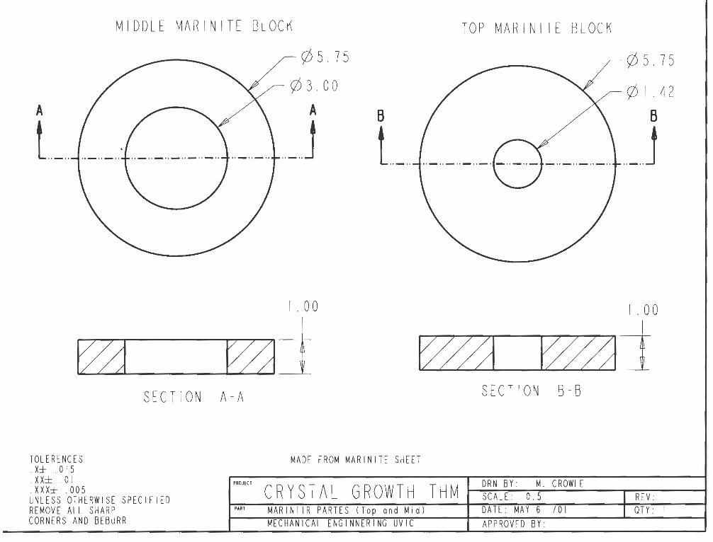
A
t.._
MIDDLE MARINITE BLOCK
¢ 5. 75
¢ 3. 00
A
,_J
I . 0 0
TOP MARINITE BLOCK
B
t.._
¢ 5. 75
¢ I . 42
B
.. _..J
I . 0 0
~ ~j t/m r;mj SECTION A-A
TOLERENCES . X± . 015 . XX± . 0 I . XXX± . 005 UNLESS OTHERWISE SPECIFIED REMOVE ALL SHARP CORNERS AND BEBURR
PROJECT
PART
SECTION B-B
MADE FROM MARINITE SHEET
REV: CRYSTAL GROWTH THM DRN BY: M. CROWLE SCALE: 0.5
MARINITR PARTES (Top and Mid l DATE: MA Y 6 /01 QTY: I MECHANICAL ENGINNERING UVIC APPROVED BY:
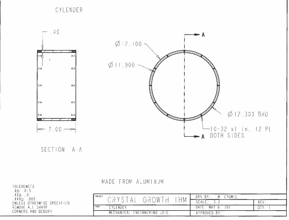
CYLENDER
r- • 40
/ / / /
=:::i c:
= :> c:
= :> c:
= :> c :
= :> c:
/
~7.00~
TOLERENCES . X± . 015 . XX± . 0 I . XXX± . 005
SECTION A-A
UNLESS OTHERWISE SPECIFIED REMOVE ALL SHARP CORNERS AND BEBURR
•A ¢12.700
¢ 11. 900
¢12.300 BHD
! l_I0-32 xi in. 12 PL 1 .. A BOTH SI DES
MADE FROM ALUMINUM
DRN BY: M. CROWLE PROJECT
CRYSTAL GROWTH THM REV: SCALE: 0.2 PAR! CYLENDER DAff: MAY 6 /01 QTY: I
ME CH A Nl CA l E NG I N N ER f NG U V I C APPROVED BY:
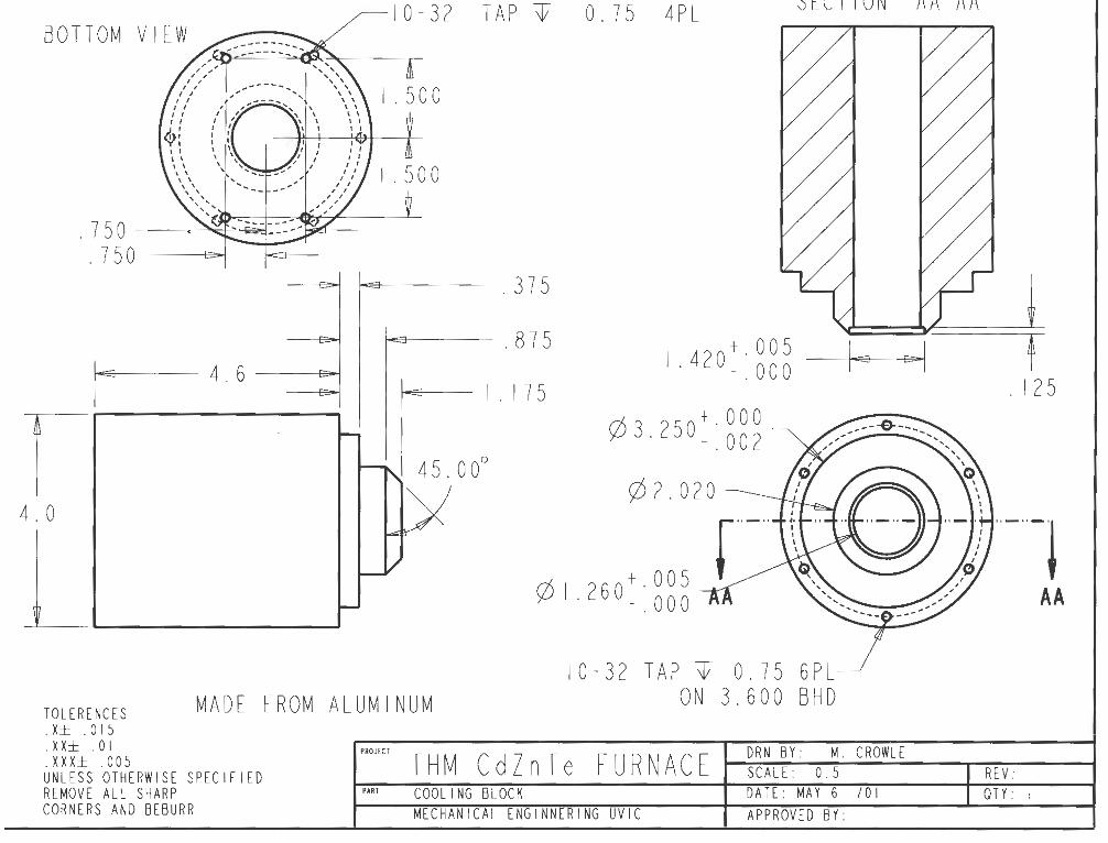
BOTTOM VIEW
.750 · "~I ~ . 750
1
..,, 4 . 6
r 4.0
10-32 TAP T 0.75 4PL
.375
.875
I . I 7 5
1.420+.005 - . 0 0 0
¢3.250+.000 -.002
¢2.020
¢ 1.260+.005 -.000
0tll IUN AA-AA
IEJ Doi
TOLERENCES . X± . 015
MADE FROM ALUMINUM 10-32 TAP w 0. 75 6PL
ON 3.600 BHD
. XX± . 0 I
. XXX± . 005 UNLESS OTHERWISE SPECIFIED REMOVE ALL SHARP CORNERS AND BEBURR
PROJECT
PART
DRN BY: M. CROWLE THM CdZnTe FURNACE SCALE: 0.5 COOLING BLOCK DATE: MAY 6 IOI MECHANICAL ENGINNERING UVIC APPROVED BY:
t . I 2 5
··-·-, AA
REV: QTY: I
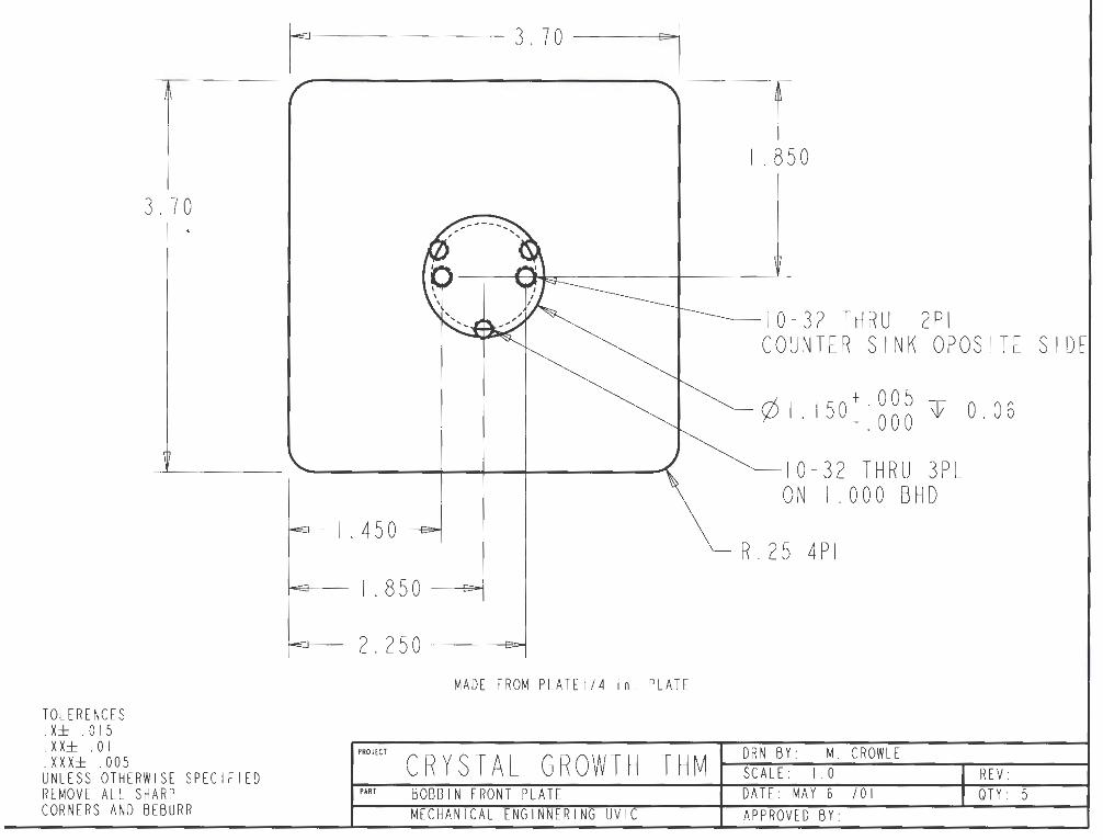
TOLERENCES . X± . 015 . XX± . 0 I . XXX± . 005
3. 7 0
UNLESS OTHERWISE SPECIFIED REMOVE ALL SHARP CORNERS AND BEBURR
IE 3.70 ""I
I I. 850
----10-32 THRU 2PL COUNTER SINK OPOSITE SIDE
rf.. + 005 )L/1.150_: 000 T 0.06
10-32 THRU 3PL ON I . 0 0 0 B HD
I . 450 R.25 4PL
IES I . 850 Doi
IES 2.250 Doi
MADE FROM PLATEl/4 in. PLATE
PROJECT
CRYSTAL GROWTH THM REV: DRN BY: M. CROWLE SCALE: 1.0
PART BOBBIN FRONT PLATE DATE: MAY 6 /01 OTY: 5 MECHANICAL ENGINNERING UVIC APPROVED BY:
Surname: Crowle
Place of Birth: Durban South Africa
Educational Institutions Attended:
University of Victoria McGill University John Abbott Collage
Degrees Awarded:
Given Names: Michael Richard
1998 to 2002 1993 to 1998 1990 to 1993
B.Sc.Eng. McGill University 1998
Honours and Awards:
Olympic Torch Scholarship Fund Award 2000
