llrf strategy flash · hw design sw design at flash maintain llrf at flash improve llrf at flash...
TRANSCRIPT

LLRF Development at FLASH, March 29, 20081
"LLRF system development for the XFEL and performance evaluation at FLASH"
S. SimrockDESY, Hamburg, Germany

LLRF Development at FLASH, March 29, 2008
or
Why does the LLRF development requireso little machine study time at FLASH

LLRF Development at FLASH, March 29, 2008
Outline
• Development for the XFEL– Strategy– Hardware– Software
• Performance Evaluation at FLASH– Machine Studies
• Upgrade Plans for FLASH

LLRF Development at FLASH, March 29, 2008
Tasks for LLRF System for XFEL
Requirement Capture
Design and buildXFEL LLRF System
Install and Commission LLRF System
Team building
Conceptual Design
Work Breakdown
LLRF MachineStudies
at FLASHHW Design SW Design
Maintain LLRF at FLASH
Improve LLRF at FLASH
Production

LLRF Development at FLASH, March 29, 2008
Strategies (1)
COTS
In-house
Copy
Design and buildXFEL LLRF System
Outsource
Install and CommissionLLRF System
Outsource In-house
Collaboration
Evaluate commissioningprocedures at FLASH
Install XFEL LLRF system at FLASH
Collaboration

LLRF Development at FLASH, March 29, 2008
Strategies (2)Team Building
Hire qualifiedpeople withexperience
Hire and trainyoung people
Qualifiedcollaboration
Train newcollaboration
Requirement Capture
Industrial Study(long learning process)
Requirement writing by team(problem with experience)
Trial and Error
Learn from experienceat FLASH

LLRF Development at FLASH, March 29, 2008
Strategies (3)
Identify Problems withLLRF System at FLASH
FLASH/XFEL equal priority
Synergy FLASH/XFEL LLRF
Dilemma: FLASH needs short termXFEL needs long term
solution
LLRF Improvement at FLASH Conceptual Design
LLRF Review
System Engineering Language
System Engineering Tool
System Engineering Methodology
Learn from FLASH

LLRF Development at FLASH, March 29, 2008
Strategies (4)
SIMCON
SIMCON DSP
SIMCON Gigalink
ATCA
HW Design
ATCA DevelopmentSystem at FLASH
SIMCON DevelopmentSystem at FLASH
SW Design
EvaluatePrototypeat FLASH
Lab SystemCavity Simulator
Studies at CMTB

Stefan Simrock, DESYLLRF-ATCA Review, Dec. 3, 2007 4
XFELThe EuropeanX-Ray Laser Project X-Ray Free-Electron Laser
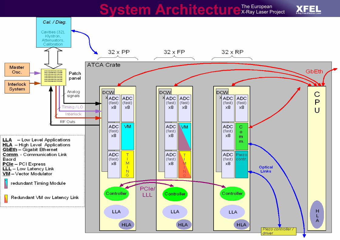
System Architecture Details

Stefan Simrock, DESYLLRF-ATCA Review, Dec. 3, 2007 6
XFELThe EuropeanX-Ray Laser Project X-Ray Free-Electron Laser
Signal diagram for RF Control (1 RF Station)
LLRF
KlystronDrive
CavitySignals
~130 x
InterlockSignals
BeamDiagnostics
Control System
~10 x
~10 x
1 x
Cavity Tuner fast and slow
Operator Console
HPRF ~3 x
32 x
32 x
RF Power transmission
64 x
Database
~3 x
~3000x(derived signals) HPRF

S. Simrock, Summary LLRF ReviewXFEL Meeting, January 15, 2008 8
XFELThe EuropeanX-Ray Laser Project X-Ray Free-Electron Laser
Challenge for Software Development
P23A77,A67,A31, A13
P19A34,A54,A109, A23
P21A12,A78,
A102, A54 P14A49,A91,A35, A28
P21A29,A22,A83, A08
P08A18,A11,A71, A29
P07A21,A88,A99, A71
Pxz = Processor (FPGA,DSP, CPU)
Anm = Application
Ckl = Communication Link
C18C13
C09
C21
C03
C19
C08
C27C11
I/O
I/O
I/O

S. Simrock, Summary LLRF ReviewXFEL Meeting, January 15, 2008 9
XFELThe EuropeanX-Ray Laser Project X-Ray Free-Electron Laser
Use cases for LLRF System (RF Station)
Standby
EstablishmoderateRF power
Enablemeasurements
Field control
ResonanceControl
Calibration
BeamFeedback
Change Settings
Parameter Optimization
ExceptionDetection and
Handling
Klystron, ModulatorPower Transmission
Cavity, couplerFrequency Tuners
Timing, SynchronizationLLRF hardwareLLRF software
Networks
Motor tunerPiezo tuner
DatabaseApplication
Field errorRobustness
GradientPulse length, rep. rate
Beam currentPrepare new settingsEnergy
Beam load. Comp.Bunch compression
DeterminePerformance
Statistics
Stefan Simrock, DESYLLRF-ATCA Review, Dec. 3, 2007 12
XFELThe EuropeanX-Ray Laser Project X-Ray Free-Electron Laser
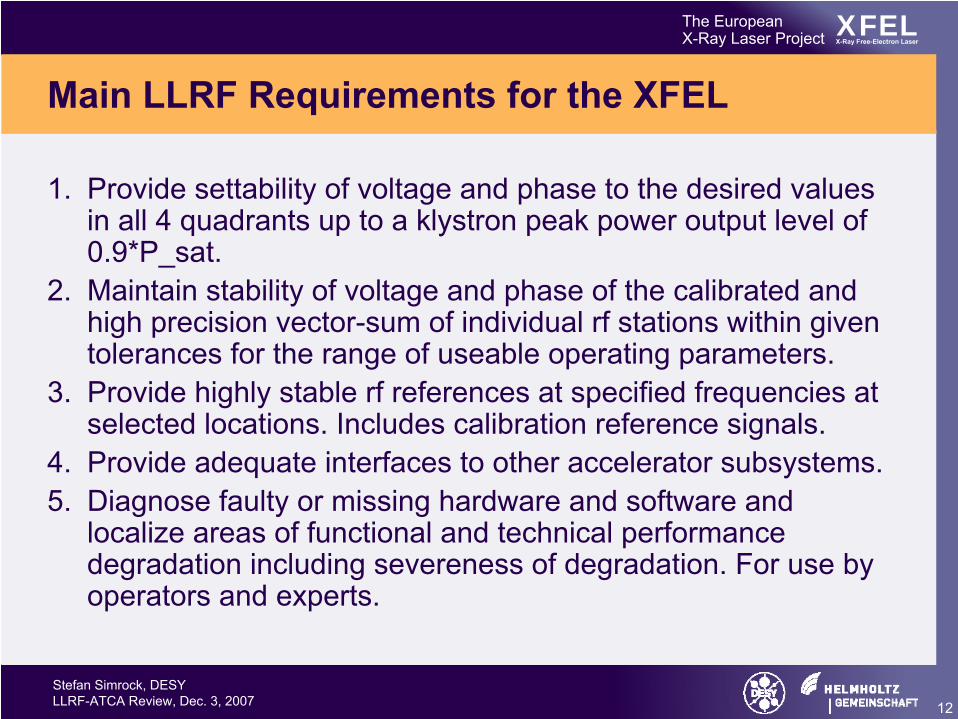
Main LLRF Requirements for the XFEL
1. Provide settability of voltage and phase to the desired values in all 4 quadrants up to a klystron peak power output level of 0.9*P_sat.
2. Maintain stability of voltage and phase of the calibrated and high precision vector-sum of individual rf stations within given tolerances for the range of useable operating parameters.
3. Provide highly stable rf references at specified frequencies at selected locations. Includes calibration reference signals.
4. Provide adequate interfaces to other accelerator subsystems.5. Diagnose faulty or missing hardware and software and
localize areas of functional and technical performance degradation including severeness of degradation. For use by operators and experts.

Stefan Simrock, DESYLLRF-ATCA Review, Dec. 3, 2007 13
XFELThe EuropeanX-Ray Laser Project X-Ray Free-Electron Laser
Main Requirements for the XFEL (Cnt’d)
6. Optimize and/or limit operational and system internal parameterssuch that the performance function based on rms field stability, accelerator availability, and component lifetime is maximized.
7. Provide a simulation mode, where the klystron-cavity system is replaced by a simulator and which provides performance predictions for planned parameter changes.
8. Provide a high degree of automation of operation to assist the operator and system experts.
9. Provide calibration functions for selected signals. 10.Provide low and high level applications supporting automation. 11.Provide exception detection and handling. 12.Provide operating modes for rf system conditioning (ex. coupler and
cavity). 13.Support rf system and accelerator commissioning procedures.

XFELThe EuropeanX-Ray Laser Project X-Ray Free-Electron Laser
Architecture for the LLRF system based on the ATCA standard - Tomasz Jezynski, DESY LLRF Review, DESY, December 3, 2007
Concept – modular system based on ATCA
Problems:
• analog signals in ATCA are not defined
• no analog IOs connected from rear
XFELThe EuropeanX-Ray Laser Project X-Ray Free-Electron Laser
Architecture for the LLRF system based on the ATCA standard - Tomasz Jezynski, DESY LLRF Review, DESY, December 3, 2007
System Architecture

XFELThe EuropeanX-Ray Laser Project X-Ray Free-Electron Laser
ATCA Carrier Board - Tomasz Jezynski, DESY LLRF Review, DESY, December 3, 20077
AMC
AMC
AMC
Zone
1Zo
ne 2
Zone
3
DSP25 x 25
DSP25 x 25
DSP25 x 25
User FPGAFF1513
ATC210Main power
regulator
M M
M M
M M
M MMM
M MM M
M MM M
Powerreg.
Powerreg.
Powerreg.
Powerreg.
Powerreg.
Powerreg.
MainframeFPGA
Powerreg.
Powerreg.
Powerreg.
clk
PCIeswitch
clk
Gbitswitch
clk
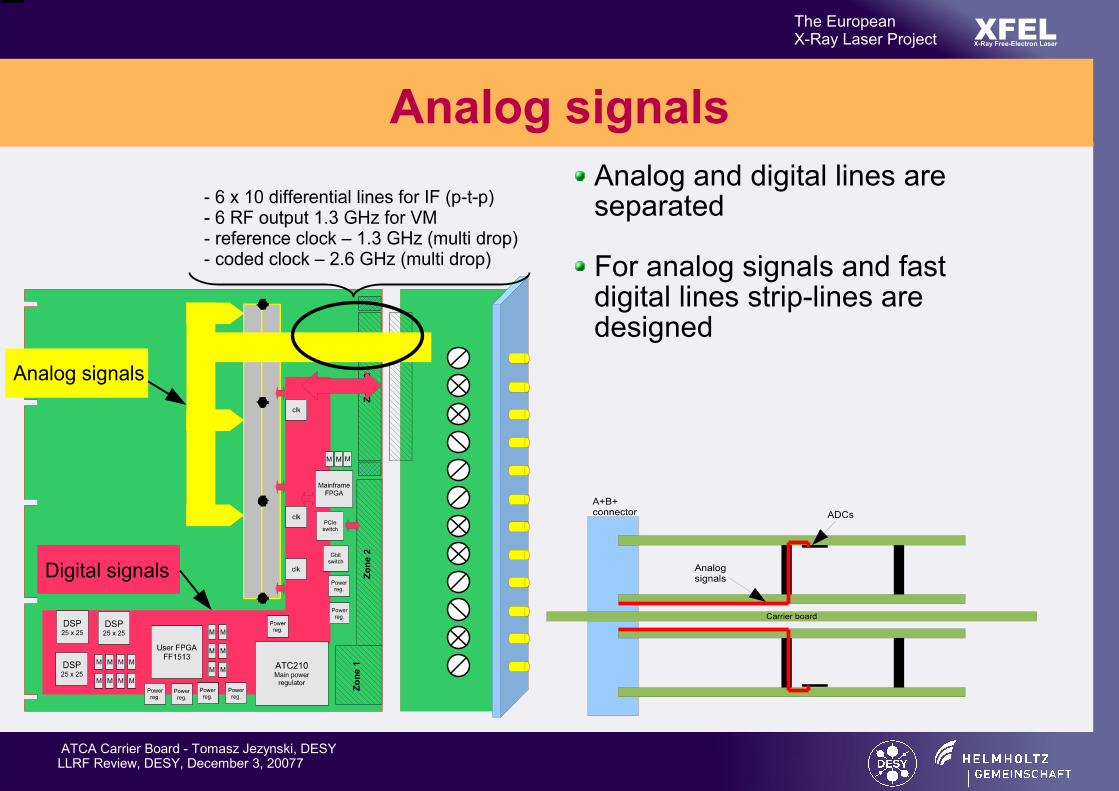
Characteristic signals for the LLRF system
Carrier board - concept
XFELThe EuropeanX-Ray Laser Project X-Ray Free-Electron Laser
ATCA Carrier Board - Tomasz Jezynski, DESY LLRF Review, DESY, December 3, 20077
Analog and digital lines are separated
For analog signals and fast digital lines strip-lines are designed
Analog signals

Przemek Sekalski, Department of Microelectronics and Computer Science, Technical University of Lodz, PolandReview of LLRF system based on ATCA standard, Dec 3-4, 2007 3
XFELThe EuropeanX-Ray Laser Project X-Ray Free-Electron Laser
The main aim of Piezo Control system
Drive the piezoelements assembled in fast tuners frames to minimize the Lorentz force and microphonics effects
On-line frequency detuning calculation
Microphonics measurement (i.e. diagnostics of cryogenic system)
Dimensions: 10x10x36mmManufacturer: PI
Dimensions: 10x10x30mmManufacturer: NOLIAC

Przemek Sekalski, Department of Microelectronics and Computer Science, Technical University of Lodz, PolandReview of LLRF system based on ATCA standard, Dec 3-4, 2007 17
XFELThe EuropeanX-Ray Laser Project X-Ray Free-Electron Laser
Results
FLASH, ACC6Acc. Grad = 22MV/m, Rep. Rate=5Hz

3
Frank Ludwig, DESYXFEL-LLRF-ATCA Meeting, 3-4 December 2007
XFELThe EuropeanX-Ray Laser Project
X-Ray Free-Electron Laser
Cavity Field Detection Requirements
deg 0.1 %, 1.0A/A
rms
rms==
ϕΔΔ
deg 0.03 %, 03.0A/A
rms
rms==
ϕΔΔ
deg 0.01 %, 01.0A/A
rms
rms==
ϕΔΔ
GHz3.1fCAV =
Amplitude andPhase stability :
n Requirements for different LLRF-stations:

5
Frank Ludwig, DESYXFEL-LLRF-ATCA Meeting, 3-4 December 2007
XFELThe EuropeanX-Ray Laser Project
X-Ray Free-Electron Laser
Downconverter for LLRF
Intermediate frequency [10MHz, 50MHz]:
Master-Oscillator
ADC
LO-input
ADC clock
BPFRF-input
fΔ
sf
Digital
I,Q-Detection
IFf
CICFilter
Receiver CH1
LNA
Sampling and Field Detection
LO and CLK Generation
Input
Calibration
ϕ,A
Muti-channel downconverter
Sample frequency [50MHz-130MHz]
Single cavity field in amplitude and phase

6
Frank Ludwig, DESYXFEL-LLRF-ATCA Meeting, 3-4 December 2007
XFELThe EuropeanX-Ray Laser Project
X-Ray Free-Electron Laser
Achieved Performance from FLASH studies
n Multi-channel downconverter :
8 channel Gilber-mixer receiver VME based+ SIMCON DSP (14-bit ADCs) VME based
Stability results (single channel) :- Shortterm, bunch-to-bunch (800us) :
egd 0.0092 %, 015.0A/A rmsrms == ϕΔΔ
- Midterm, pulse-to-pulse (10min) : egd 0.0147 %, 016.0A/A rmsrms == ϕΔΔ
- Longterm, drifts (1hour) : deg 0.05 %, 09.0A/A pkpkpkpk == ϕΔΔ
n Pulse-to-Pulse Beam Stability :
θA = 2e-3/°C, θP = 0.2°/°C(Need for drift calibration)
0.022%
0.016%
Desired XFEL value
Main and Booster section requirements are fulfilled -Injector and 3rd harmonic requirements only nearly.
Can the ATCA system fulfill this too?

8
Frank Ludwig, DESYXFEL-LLRF-ATCA Meeting, 3-4 December 2007
XFELThe EuropeanX-Ray Laser Project
X-Ray Free-Electron Laser
Injector and 3rd Harmonic Section Downconverter
Cavity Signalsforward, reflected, probe
24
Universal IO
Upconverter
ADCs
fs LaserReference
LO Generation& Distribution
Receiver
Laser toRF-Reference
ATCA Crate
Piezo Driver
LO
LO
RF Reference
IF Signalsforward, reflected, probe
24x4
Drift Calibration+ Reference
Calibration Line
1 Timing
24 2424
n RackLayout :
‚Pizza boxed‘ ATCA System or SIMCON-DSP, ESECON, ACB

Krzysztof Czuba, ISELLRF reviev, DESY, 3.12.2007,
XFELThe EuropeanX-Ray Laser Project X-Ray Free-Electron Laser
Need for Precise Synchronization
• Electronic devices should be synchronized with high accuracy • Required jitter for phase reference signals:
– 0.1 ps short term (10 fs at some locations in XFEL)– 1 ps long term
~
RF Station
Klystron LLRFCavities
RF Station
Klystron LLRFCavities
RF Station
Klystron LLRFCavitiesInjector
Timing
Distribution SystemMasterOscillator
Timing Signals
Phase Reference Signals

Wojciech Jalmuzna, Technical University of Lodz, Department of Microelectronics and Computer ScienceXFEL-LLRF-ATCA Meeting, 3-4 December 2007 5
XFELThe EuropeanX-Ray Laser Project X-Ray Free-Electron Laser
Overview of the distributed system
cryomodule cryomodule cryomodule cryomodule
klystron
24 channels
8 channelboard3x 8 channelboard3x 8 channel
board3x 8 channelboard3x 8 channel
board3x 8 channelboard3x 8 channel
board3x
Computationboard
DACboard
multiple FPGAsmultiple DSPsembedded systemssurrounding devices

Grzegorz Jablonski, Technical University of Lodz, Department of Microelectronics and Computer ScienceXFEL-LLRF-ATCA Meeting, 3-4 December 2007 14
XFELThe EuropeanX-Ray Laser Project
X-Ray Free-Electron Laser
Control System
Against the background of the whole system
RF station
Controller
Low Level App. High Level App.
Piezo Control
interfaces provided by the controller
functions performed by the controller 5 different functions
of the controller

Wojciech Jalmuzna, Technical University of Lodz, Department of Microelectronics and Computer ScienceXFEL-LLRF-ATCA Meeting, 3-4 December 2007 7
XFELThe EuropeanX-Ray Laser Project X-Ray Free-Electron Laser
Possible algorithm locations
FPGADSPEmbedded
system
CPUson site
CalculationClusters
RemoteCPUs
Low LevelApplications
High LevelApplications
Controller
5 ns200 ns50 ms

Wojciech Jalmuzna, Technical University of Lodz, Department of Microelectronics and Computer ScienceXFEL-LLRF-ATCA Meeting, 3-4 December 2007 11
XFELThe EuropeanX-Ray Laser Project X-Ray Free-Electron Laser
Low Level Applications
This includes:
- Adaptive Feed-Forward
- System Identification
- Loop gain and loop phase calculation
- detuning and loaded Q calculation
- Vector sum calibration
- Beam Diagnostic
- Exception Detection and Handling

Wojciech Jalmuzna, Technical University of Lodz, Department of Microelectronics and Computer ScienceXFEL-LLRF-ATCA Meeting, 3-4 December 2007 12
XFELThe EuropeanX-Ray Laser Project X-Ray Free-Electron Laser
High Level Applications
This includes:
- Adaptive Feed-Forward
- Vector sum calibration
- Beam Diagnostic
- Automated frequency tuning
- Exception Detection and Handling
- RF-Gun control

Wojciech Jalmuzna, Technical University of Lodz, Department of Microelectronics and Computer ScienceXFEL-LLRF-ATCA Meeting, 3-4 December 2007 18
XFELThe EuropeanX-Ray Laser Project X-Ray Free-Electron Laser
Development environmentprobesignals
Down-converterIF=54MHz
SIMCONDSP
VectorModulator
controlsignal
Down-converterIF=54MHz
SIMCONDSP
Down-converterIF=54MHz
SIMCONDSP
forwardsignals
reflectedsignals
ACB
probesignals
toklystron
Before ATCA system arrives:

Grzegorz Jablonski, Technical University of Lodz, Department of Microelectronics and Computer ScienceXFEL-LLRF-ATCA Meeting, 3-4 December 2007 11
XFELThe EuropeanX-Ray Laser Project
X-Ray Free-Electron Laser
Functional featuresField detection module includes:– Field measurement – Support for different IFs– Input linearization– Field calibration– Field I component detection– Field Q component detection– Components conversion to field amplitude– Components conversion to field phase– Measurement filtering
Feedback module includes:– Field error calculation– PID transfer function– MIMO controller
Output module includes:– Output linearization– Correction tables– Offset compensation– Control signal adjustments– Control signal limiters– Loop phase adjustment– Loop gain adjustment– Output delay
The features can be used both in control and diagnostic mode.
Diagnostic mode provides such functionality as SEL or Frequency Sweep mode etc.

Schematic View of the LLRF Control System
~
AD
C
AD
C
÷÷ø
öççè
æ -
ab
ba
÷÷ø
öççè
æ -
ab
ba
å
DA
C
DA
C
úúúú
û
ù
êêêê
ë
é
++
++
++
++
++
++
++
++
--
--
--
--
--
--
--
--
1
1)(
1
1)(
1
1)(
1
1)(
1
22
2
22
1
22
2
22221
21
2
21
1
21
2
2121
1
12
2
12
1
12
2
12121
11
2
11
1
11
2
1111
zdzc
zbzatK
zdzc
zbzatK
zdzc
zbzatK
zdzc
zbzatK
Waveguide
Masteroscillator
Vectormodulator Klystron
LO
1.3 Ghz
cryomodule
8x
FPGA System
FeedforwardSetpoint
MIMO -Controller
LO1.3 Ghz+ 250 kHz
1.3 Ghz+ 250 kHz
250 kHz 250 kHz
1.3 Ghzfield probe
1.3 Ghzfield probe
clock clock
F =1MHz F =1MHz
Calibration
IyQy
Ie
Qr
Ir
Qe
IuQu
If
Qf Qcu ,
Icu ,
Figure: Control system Schematic system signals
Christian Schmidt µ ¶ 9/24 · ¸

Controller Structure
so far a decentralized P Controller is usednew FPGA implemented controller is given by:
MIMO-Controller
x
x
GN_RAW_I
GN_RAW_Q
e i
eq
GN_SCA_I
GN_SCA_Q
SHIFT
x
SHIFT
K ij z=k ijaij⋅z
−2bij⋅z−11
cij⋅z−2d ij⋅z
−11
uc , r
uc ,i
K11 z K21 z
K22 z K12 z
x
x
x
x
+
+
tuning 20 parameters manually is not possible for users
Christian Schmidt µ ¶ 16/24 · ¸
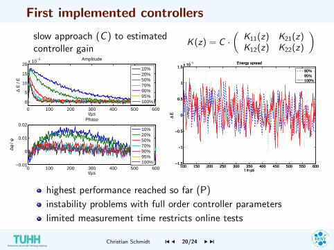
First implemented controllers
slow approach (C ) to estimatedcontroller gain
K (z) = C ·(
K11(z) K21(z)K12(z) K22(z)
)
0 100 200 300 400 500 600
0
5
10
15
20x 10
−3
t/µs
∆ E
/ E
Amplitude
0 100 200 300 400 500 600−0.01
0
0.01
0.02
t/µs
∆φ /
φ
Phase
10%20%50%70%90%95%100%
10%20%50%70%90%95%100%
100 150 200 250 300 350 400 450 500 550 600−1.5
−1
−0.5
0
0.5
1
1.5x 10
−3
t in µs∆
E
Energy spread
90%95%100%
highest performance reached so far (P)
instability problems with full order controller parameters
limited measurement time restricts online tests
Christian Schmidt µ ¶ 20/24 · ¸
S. Simrock, Summary LLRF ReviewXFEL Meeting, January 15, 2008 5
XFELThe EuropeanX-Ray Laser Project X-Ray Free-Electron Laser
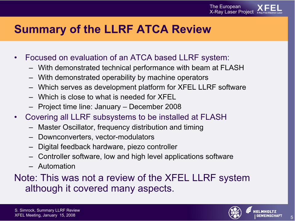
Summary of the LLRF ATCA Review
• Focused on evaluation of an ATCA based LLRF system:– With demonstrated technical performance with beam at FLASH– With demonstrated operability by machine operators– Which serves as development platform for XFEL LLRF software– Which is close to what is needed for XFEL– Project time line: January – December 2008
• Covering all LLRF subsystems to be installed at FLASH– Master Oscillator, frequency distribution and timing– Downconverters, vector-modulators– Digital feedback hardware, piezo controller– Controller software, low and high level applications software– Automation
Note: This was not a review of the XFEL LLRF system although it covered many aspects.

S. Simrock, Summary LLRF ReviewXFEL Meeting, January 15, 2008 7
XFELThe EuropeanX-Ray Laser Project X-Ray Free-Electron Laser
Individual Comments from reviewers
• The change from R&D to production mode for the XFEL requires a change of mode of operation :– Senior personnel (responsible for workpackages) from
collaboration partners must join the core team at DESY for a significant portion of their time (~6 months / year) and commit their participation for the duration of the project.
– Collobration partner must be involved in project management– Must commit to agreed schedule and deliverables– Work on LLRF cannot be sacrified by committments toward the
universities.– Intellectual property must be accessible to all collaboration
partners

LLRF Development at FLASH, March 29, 2008
Performance at FLASH

LLRF Development at FLASH, March 29, 2008
Beam Energy Stability
• So far at FLASH a beam stability of 0.008% was achieved during 01/2008 studies by using the 250kHz modulation scheme for cavity field detection and on-crest operation.– Unfortunately this result was not reproducible although a
3 times lower noise down-converter was in operation. For off-crest operation, this is still unknown and would have a great impact for the future 3.9GHz system and the XFEL.
– Especially the influence of the rf-phase and ACC1 gradient is unclear. To clarify this, the following measurements were suggested:

LLRF Development at FLASH, March 29, 2008
Proposed Measurements• Semi-automized vector-sum beam based
calibration (CS).• Accurate 3-stub tuner adjustment (CS, VA).• ACC1 feedback gain dependent beam stability
measurements using SR-BC2 (CS, FL).• Off-crest gain sweep using low-noise, but highly
nonlinear down-converter (CS, FL).• Off-crest beam stability in dependence of rf-
phase and ACC1 gradient (CS, FL).• Off-crest beam stability in dependence of IQ-
driver degradation (GM, FL).• MO Reference feed into installed down-converter
(GM, FL).
Note: The blue marked items were successfully performed.

LLRF Development at FLASH, March 29, 2008
Energy stability as function of feedback gain
Gain
Energy stability

LLRF Development at FLASH, March 29, 2008
Operational Experience
LLRF Development at FLASH, March 29, 2008
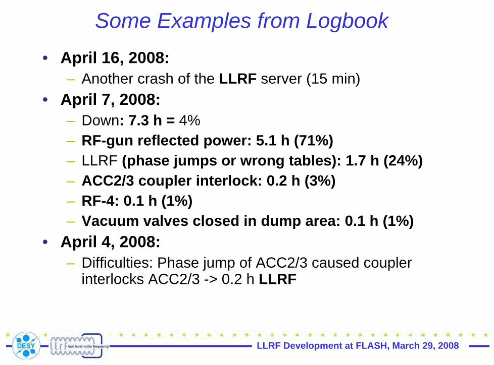
Some Examples from Logbook• April 16, 2008:
– Another crash of the LLRF server (15 min)• April 7, 2008:
– Down: 7.3 h = 4%– RF-gun reflected power: 5.1 h (71%) – LLRF (phase jumps or wrong tables): 1.7 h (24%) – ACC2/3 coupler interlock: 0.2 h (3%) – RF-4: 0.1 h (1%) – Vacuum valves closed in dump area: 0.1 h (1%)
• April 4, 2008:– Difficulties: Phase jump of ACC2/3 caused coupler
interlocks ACC2/3 -> 0.2 h LLRF

LLRF Development at FLASH, March 29, 2008
Some Examples from Logbook• April 1, 2008:
– Problem with LLRF in ACC456, adaptive FF error after interlock trip (1 h)
• March, 2008:– LLRF (lost ACC1 tables): 0.1 h (3%) – wrong calibrations ACC1 after LLRF studies (1 h) – difficulties to boot LLRF server after LLRF studies (1 h) – There is something wrong with the ACC2&3 LLRF:
quench, leave LLRF running without FB. – The klystron is in saturation -> amplitude is not regulated
by LLRF (RF Gun).– Lost 1 h due to messed up LLRF of ACC1 (by night shift,
fixed by Valeri) – ACC1 calibrations wrong (after LLRF studies in Monday
night shift), 1 h

LLRF Development at FLASH, March 29, 2008
Some Examples from Logbook– LLRF: 0.1 h (3%) :Jump ACC1 – LLRF: 0.1 h (10%) , Phase and amplitude jumps of
ACC1 and ACC2/3 – It looks like we have some problem with KL5 or
LLRF. – LLRF: 2.5 h (10%) : Phase jump ACC1 – LLRF: 2 h (12%) : 81 MHz LLRF: 1.5 h (7%)
• Work on MO: 1 h • Wrong LLRF tables ACC1: 0.3 h • Sudden phase jump ACC1: 0.2 h
– LLRF adjustments: 1 h (21%)
LLRF Development at FLASH, March 29, 2008
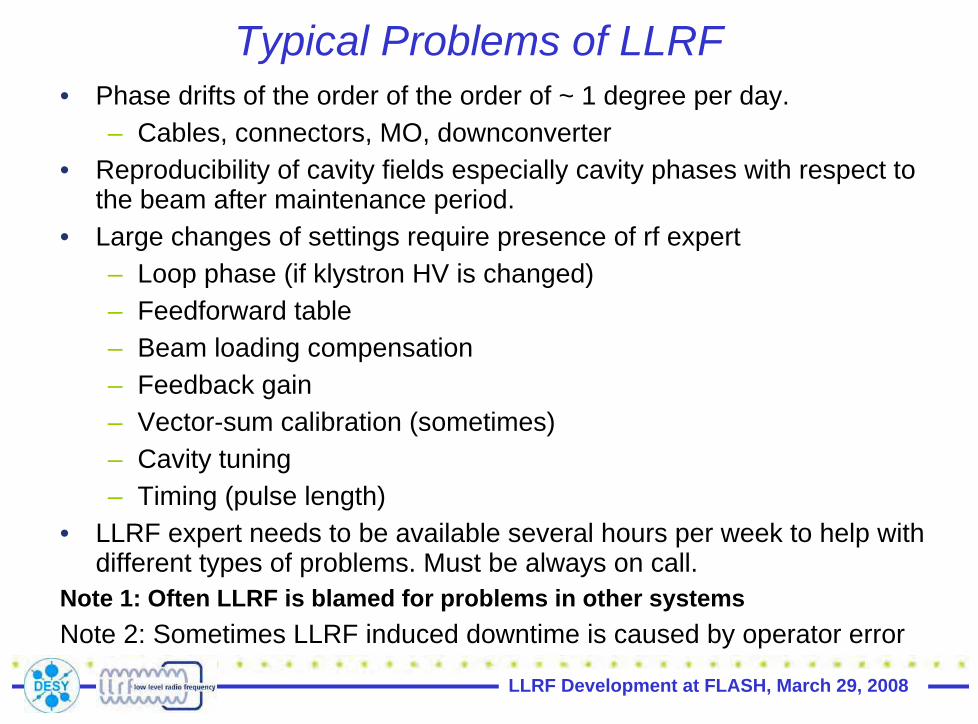
Typical Problems of LLRF• Phase drifts of the order of the order of ~ 1 degree per day.
– Cables, connectors, MO, downconverter• Reproducibility of cavity fields especially cavity phases with respect to
the beam after maintenance period.• Large changes of settings require presence of rf expert
– Loop phase (if klystron HV is changed)– Feedforward table– Beam loading compensation– Feedback gain– Vector-sum calibration (sometimes)– Cavity tuning– Timing (pulse length)
• LLRF expert needs to be available several hours per week to help withdifferent types of problems. Must be always on call.
Note 1: Often LLRF is blamed for problems in other systemsNote 2: Sometimes LLRF induced downtime is caused by operator error

LLRF Development at FLASH, March 29, 2008
Selected Studies Results

LLRF Development at FLASH, March 29, 2008
LLRF Studies Sep. 2007 (1)• Test of Multichannel Downconverter for LLRF Matthias Hoffmann• Beam based beam loading compensation at ACC1 Elmar Vogel• Beam based ACC1 rf field stability measurement using BC2 beam
diagnostics Elmar Vogel• Multicavity Complex Controller (MCC) Tomasz Czarski• Vector-Sum Calibration with Beam and Beam Diagnostics
Valeri Ayvazyan• For./ref. rf power cal, w/wout beam, probe calculation
Waldemar Koprek• Multi-bunch transient detection with different electronics
Petr Morozov• Grad./phase calibration with full beam loading Valeri Ayvazyan• Operation at different gradients (gradient spread) Valeri Ayvazyan• Operation close to limits (klystron saturation., cavity/coupler limit)
Wojciech Cichalewski• Beam Based RF Amplitude and Phase Calibrations Valeri
Ayvazyan

LLRF Development at FLASH, March 29, 2008
LLRF Studies Sep. 2007 (2)• Radiation effects on electronics Mariusz Grecki• Physical System Parameters Identification Christian Schmidt • Off-crest operation in ACC456 Valeri Ayvazyan• Performance evaluation of ILC Americas No. 1 LLRF Controller
Gustavo Cancelo• Evaluate ILC America No. 1 Downconverter and
Vectormodulator Brian Chase • Performance evaluation of new FLASH MO and Distr. with
beam Henning Weddig• Evaluation of Operational Procedures for Automation
Wojciech Cichalewski• Test of Components needed for Automation Boguslaw Koseda• Operation of universal controller Wojciech Jalmuzna• Test of new features in LLRF controller at ACC1 Waldemar
Koprek

LLRF Development at FLASH, March 29, 2008
LLRF Studies January 2008 (3)• Beam stability obtained by various rf control settings Elmar Vogel • Beam based beam loading compensation at ACC1 Elmar Vogel • Downconverter Drift Calibration and Compensation BRIAN
CHASE • Vector-sum calibration optimization GUSTAVO CANCELO • Correlation studies beam vs rf measurements Matthias Hoffmann • System Identification and performance testing of MIMO-LTI
feedback Christian Schmidt • Iterative learning Controller design Christian Schmidt • Beam phase measurement with single bunch Petr Morozov• Investigation on the relationship between module gradient and
Neutron/Gamma radiation dose Bhaskar Mukherjee• Measurement of dark current induced Neutron/Gamma Dose
Bhaskar Mukherjee• Lorentz force detuning with piezo tuners Mariusz Grecki

LLRF Development at FLASH, March 29, 2008
LLRF Studies Jan./Mar. 2008 (4)
• Multi-cavity scope for Lorentz Force Detunig using SimconDSPWojciech Jalmuzna
• Tests of 24 channel FPGA based controller Wojciech Jalmuzna• Evaluation of the performance of the universal controller Wojciech
Jalmuzna• Software updates in ACC1 Wojciech Jalmuzna• RF-Gun recalibration and stability measurement Waldemar
Koprek• Multi-Cavity Complex Controller Tomasz Czarski• RF Gun to ACC1 DWC signal crosstalk investigation Valeri
Ayvazyan• Multi-Cavity Complex Controller Tomasz Czarski• Beam Stability Studies of ACC1 Part I Frank Ludwig

LLRF Development at FLASH, March 29, 2008
LLRF Studies May 2008 (5)• RF Crosstalk Gun to ACC1 Günter Möller• Beam properties at BC2 without ACC39 Vogel Elmar• MIMO-LTI Christian Schmidt FPGA system evaluation for
all cryomodules Wojciech Jalmuzna• FPGA based scope evaluation for Lorentz force detuning
with active compensation using Piezo Tuners KonradPrzygoda
• Beam Stability Studies ACC1 Part II Frank Ludwig • RF-gun automation software components test Boguslaw
Koseda• Multi-Cavity Complex Controller Tomasz Czarski• Test of LLRF system parameters identification and its
applications Zheqiao Geng• RF-GUN HPC linearization Wojciech Cichalewski• HPC diagnostics power level adjustement. Wojciech
Cichalewski

LLRF 07, Knoxville, TN, Oct. 22-25, 2007
Infrastructure (Cabling, Racks, Crates)
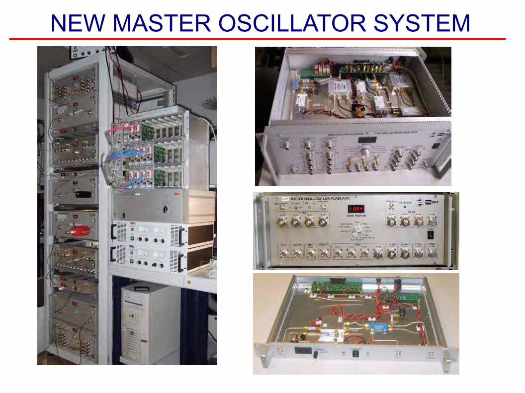
NEW MASTER OSCILLATOR SYSTEM

Cable drifts in accelerator„cable 6“ to hall 3 extension, open ended, about 100 m long 7/8´´ cellflex cable

LLRF Part I, KEK Seminar, March 7, 2008
Control of ACC1 with SIMCON

Injector beam control studies winter 2006/07 FLASH Seminar, June 19th 2007
presented at FLASH seminar by E. Vogel, June 19th 2007
ACC1 rf control: P control with beam based beam loading compensation
Problem:
• cavity with fast proportional (P) RF control corrects after 20 μs
• first 20 bunches suffer • correction within 2 bunches
required
Countermeasures:
• prediction of beam current and derivation of compensation
• measurement of beam current in real time and applying appropriate compensation
Scheme implemented for ACC1 at FLASH:
+
klystron
proportionalgain
DAC ADC
set pointtable
feedforwardtable
+
beam
+ + R/Q,

Injector beam control studies winter 2006/07 FLASH Seminar, June 19th 2007
presented at FLASH seminar by E. Vogel, June 19th 2007
‘Ideal’ gain for proportional rf control at ACC1
0 10 20 30 401E-4
1E-3
rela
tive
ener
gy s
tabi
lity
gain of proportional control
Gain resulting in most stable beam:
• error suppression for small gain values • noise amplification for large gain values • ‘ideal’ gain between both cases • best single bunch stability: ∆E/E = 2x10⁻⁴
Gain limitations:
• noise at pick up signal: G = 15 • theory w/o paying attention to
the 8/9 π mode: G = 40 • theory with paying attention
to the 8/9 π mode: G > 100
Plus points:
• XFEL requirement: ∆E/E = 10-4
• we controlled only 7 cavities (one pick up makes trouble)
• XFEL injector has four instead of only one module

Injector beam control studies winter 2006/07 FLASH Seminar, June 19th 2007
presented at FLASH seminar by E. Vogel, June 19th 2007
Actual status of the beam loading compensation
Operation with P control only (G = 15) Beam loading compensation switched on
Next steps:
Improvement of the calibration and further qualification of method by measuring energy stability of beam in BC2.

LLRF Part I, KEK Seminar, March 7, 2008
Controller Studies

FLASH Seminar DESY Jan 22, 2008
6 0 0 8 0 0 1 0 0 0 1 2 0 01 3 .9 5
1 4
1 4 .0 5
tim e [1 0 -6 s ]
MV
Z oom ed fla ttop range
6 0 0 8 0 0 1 0 0 0 1 2 0 0-0 .0 1
-0 .0 0 5
0
0 .0 0 5
0 .0 1
tim e [1 0 -6 s ]
rad
Z oom ed fla ttop range
klys tro ncavity
0 5 0 0 1 0 0 0 1 5 0 0 2 0 0 00
5
1 0
1 5
tim e [1 0 -6 s ]
MV
C avity output am plitude
0 5 0 0 1 0 0 0 1 5 0 0 2 0 0 0-0 .4
-0 .2
0
0 .2
0 .4
0 .6
0 .8
1
tim e [1 0 -6 s ]
rad
Phase o f cavity and k lys tron
klys tro ncavity
rm s =2*10-4 rm s =9*10-4 rad
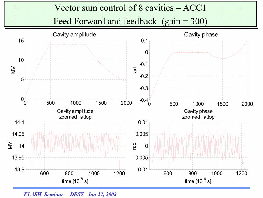
Vector sum control of 8 cavities – ACC1Feed Forward and feedback (gain=100)
FLASH Seminar DESY Jan 22, 2008
600 800 1000 120013.9
13.95
14
14.05
14.1
time [10-6 s]
Cavity amplitudezoomed flattop
MV
600 800 1000 1200-0.01
-0.005
0
0.005
0.01
time [10-6 s]
rad
Cavity phasezoomed flattop
0 500 1000 1500 20000
5
10
15Cavity amplitude
MV
0 500 1000 1500 2000-0.4
-0.3
-0.2
-0.1
0
0.1
rad
Cavity phase
Vector sum control of 8 cavities – ACC1Feed Forward and feedback (gain = 300)

FLASH Seminar DESY Jan 22, 2008
600 800 1000 120014.8
14.85
14.9
14.95
15
15.05
15.1
15.15
GAIN = 0
600 800 1000 12000
0.005
0.01
0.015
0.02
0.025
0.03GAIN = 0
600 800 1000 120014.9
14.95
15
15.05
15.1GAIN = 100
600 800 1000 1200-0.01
-0.005
0
0.005
0.01 GAIN = 100
600 800 1000 120014.9
14.95
15
15.05
15.1
time [10-6 s]
GAIN = 250
600 800 1000 1200-0.01
-0.005
0
0.005
0.01
time [10-6 s]
GAIN = 250
600 800 1000 120014.8
14.85
14.9
14.95
15
15.05
15.1
15.15
GAIN = 0
CAVITY AMPLITUDE [MV] CAVITY PHASE [rad]
Beam loading testing
SEL results
Self excited loop makes it possible to fill the cavity which is detuned from its resonance frequency
even by a large offset.
Currently it is possible to work in SEL mode using amplitude limiter on the output of the controller

SEL results (1)

SEL results (2)

SEL results (3)

SEL results (4)

Frequency Sweep Mode
This function measures the frequency response of the individual cavities using constant amplitude and slope on the phase of the control signal .
The final implementation will work with increased frequency of output update rate to get more
precise frequency control.
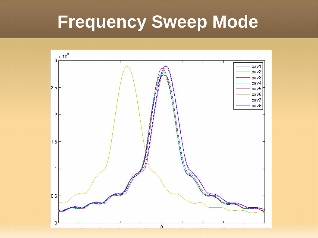
Frequency Sweep Mode

Beam stability – ACC456 (1)
The distributed version of the controller was used to drive ACC456 modules. To compare the quality
of the control between DSP and FPGA based systems beam energy stability measurements
have been performed.
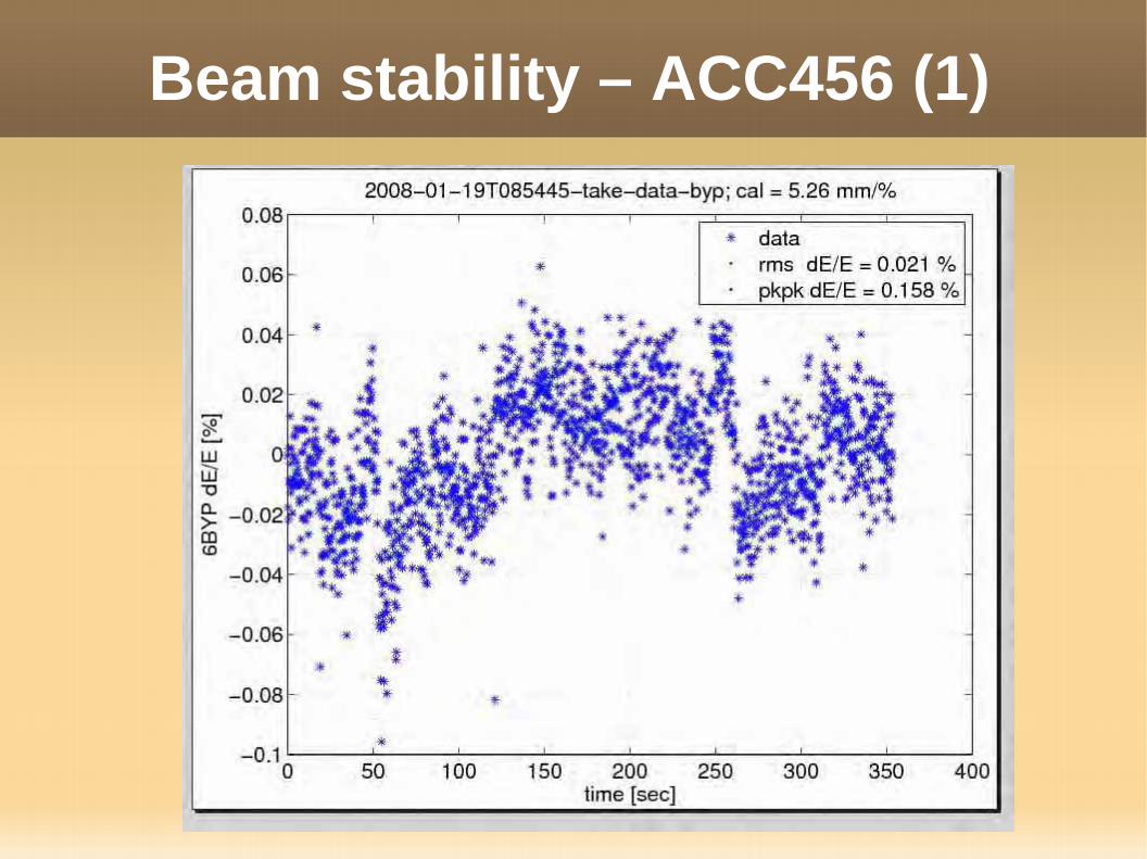
Beam stability – ACC456 (1)

Beam stability – ACC456 (2)
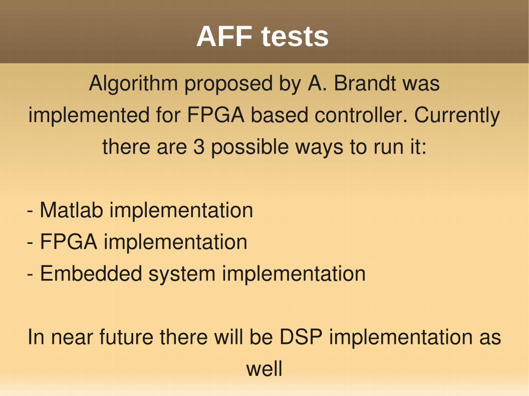
AFF testsAlgorithm proposed by A. Brandt was
implemented for FPGA based controller. Currently there are 3 possible ways to run it:
Matlab implementation FPGA implementation Embedded system implementation
In near future there will be DSP implementation as well

AFF tests (1)
LLRF Part I, KEK Seminar, March 7, 2008
RF Gun Control
Injector beam control studies winter 2006/07 FLASH Seminar, June 19th 2007
presented at FLASH seminar by E. Vogel, June 19th 2007
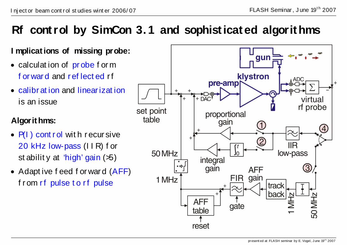
Rf control by SimCon 3.1 and sophisticated algorithms Implications of missing probe: • calculation of probe form
forward and reflected rf • calibration and linearization
is an issue
Algorithms: • P(I) control with recursive
20 kHz low-pass (IIR) for stability at ‘high’ gain (>5)
• Adaptive feed forward (AFF) from rf pulse to rf pulse
+
++
0
trackback+
+
AFFtable gate
reset
gun
∑virtual
rf probe
IIRlow-pass
FIR
klystronpre-amp
proportionalgain
integralgain AFF
gain
set pointtable
50M
Hz
1M
Hz
1
2
3
4
50MHz
1MHz
++
++
DAC
ADC
t

Injector beam control studies winter 2006/07 FLASH Seminar, June 19th 2007
presented at FLASH seminar by E. Vogel, June 19th 2007
Virtual probe signal calibration (method established at FLASH by A. Brandt)
circle fitting after frequency variation DOOCS panel for calibration parameters
Plots taken at PITZ – the plots and panels look similar at FLASH!

Injector beam control studies winter 2006/07 FLASH Seminar, June 19th 2007
presented at FLASH seminar by E. Vogel, June 19th 2007
Action of control loops - the case without control
+
++
0
trackback+
+
AFFtable gate
reset
gun
virtual
rf probe
IIRlow-pass
FIR
klystronpre-amp
proportionalgain
integralgain AFF
gain
set pointtable
50M
Hz
1M
Hz
1
2
3
4
50MHz
1MHz
++
++
DAC
ADC
t
• gun heats up within rf pulse • gun resonance frequency changes
Beam based emission phase measurement:
the emission phase changes by 8.5˚

Injector beam control studies winter 2006/07 FLASH Seminar, June 19th 2007
presented at FLASH seminar by E. Vogel, June 19th 2007
Case with P control and adaptive feed forward (AFF)
+
trackback+
+
AFFtable gate
reset
gun
virtual
rf probe
IIRlow-pass
FIR
klystronpre-amp
proportionalgain
AFFgain
set pointtable
50M
Hz
1M
Hz
1
3
50MHz
1MHz
++
++
DAC
ADC
++
0integral
gain
2t
• AFF corrects systematic errors • AFF gain of 0.4
Beam based emission phase measurement:
the emission phase changes by 0.14˚

LLRF Part I, KEK Seminar, March 7, 2008
Downconverter Performance

Frank Ludwig, DESY
Single channel receiver performance at FLASH
n Single channel stability results: n Shortterm stability 800us (bunch-to-bunch):
BW=27MHzBW=1MHz
BW=1MHzBW=1MHz
n Midterm stability 10min (pulse-to-pulse):
81 samples over 1 us1 IQ value~5 Hz through 10 minutes
Short-term, bunch-to-bunch (800us) : egd 0.0092 %, 015.0A/A rmsrms == ϕΔΔ
Mid-term, pulse-to-pulse (10min) : egd 0.0147 %, 016.0A/A rmsrms == ϕΔΔ
Long-term, drifts (1hour) : deg 0.05 %, 09.0A/A pkpkpkpk == ϕΔΔ
θA = 2e-3/°C, θP = 0.2°/°C
Parameter :
- Readout bandwidth 1MHz- VME active multi-channel receiver- SIMCON DSP (14-Bit ADC)- LO / IF leakage –72dB- Crosstalk –67...-70dB

Frank Ludwig, DESY
- 0.008% on-crest beam stability is achieved.
- The DWCs non-linearity has no influence onbeam stability for fixed machine parameters.
- DWC is not the limiting factor.
Static influence of the linearity and noise from the down-converter
n Pulse-to-Pulse Beam Stability :
0.008%
n Modified DWC performance :
- Noise degreases by a factor of 3 to <0.001%of the DWC (without IQ Driver!) within thecavity effective noise bandwidth.
- Linearity degrades from 0.5%toapprox. 5%
- Automated accurate waveguide adjustment(Indictation from off-crest LO generation limitation).
- Beam stability in dependence of gradient and phase.
Desired XFELvalue

Frank Ludwig, DESY
Motivation
What is most important for a beam stability significantly lower than 0.01% ?
Gilbert-Mixer
High-Level Mixer
Linearity
Modulation scheme
Analog HardwarePackaging
Automation VectorsumCalibrationActuator noise
Master ReferenceADC noise
Cabeling
Drifts compensation
1/f-noise[1Hz-10kHz] Scaleable
Receivers
Synch. SystemSignal Generation
Arrival time monitors
Energy spread monitors
CrosstalkDigital Hardware
Packaging
Beam-based feedbacks

Frank Ludwig, DESY
Receiver performance at FLASH
n FLASH injector :
8/9 pi mode
Down-converter biased by Cavity pickup :
- Down-converter fulfill XFEL specs- Spurius signals are below 80dBc- Cavity 8/9pi mode clearly measurable
n Vectorsum stability with closed control loop at ACC1:
Desired XFELvalue
Instability caused by 8/9pi mode

LLRF Part I, KEK Seminar, March 7, 2008
Piezotuner Control

FLASH tests

ACC6 (SP = 15 MV/m,Pforw = 220kW, rep = 5 Hz)
Cav. (1-3) Amp: 34VDly: - 4.1 ms
Cav. (4-8)Amp: 23VDly: - 4 ms

ACC6 – LFD compensation results
Piezo off
Piezo on
LLRF Part I, KEK Seminar, March 7, 2008
Klystron Linearization
DMCS W.Cichalewski Dec 12th 3
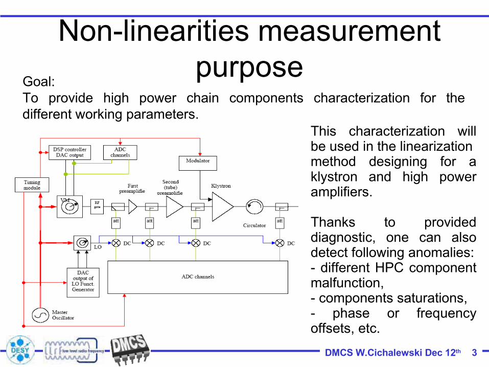
Non-linearities measurement purpose
Goal:To provide high power chain components characterization for the different working parameters.
This characterization will be used in the linearizationmethod designing for a klystron and high power amplifiers.
Thanks to provided diagnostic, one can also detect following anomalies:- different HPC component malfunction,- components saturations, - phase or frequency offsets, etc.
DMCS W.Cichalewski Dec 12th 6
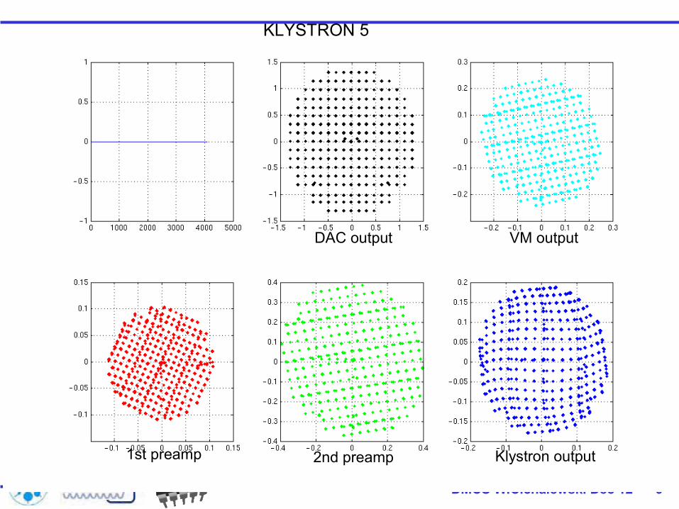
KLYSTRON 5
1st preamp 2nd preamp Klystron output
DAC output VM output

DMCS W.Cichalewski Dec 12th 13
Klystron 5 HPC linearisation results• Linearisation test had been performed using Simcon(FPGA)
controler,• Correction tables were „on” • HV level – 10800 (value on PLC) about 110kV• Two iteration of the linearisation were performed.

LLRF Part I, KEK Seminar, March 7, 2008
Radiation Measurements

Exp # 1: ResultsExp # 1: ResultsGamma does rates along FLASH during Routine OperationGamma does rates along FLASH during Routine Operation
at a gradient of ~ 21 MV/mat a gradient of ~ 21 MV/m
(R1.2)(R1.2) Gamma dose rate drops strongly with the distance from the RF gunGamma dose rate drops strongly with the distance from the RF gun..
Fig. 3Fig. 3
(R1.1)(R1.1) Accelerated dark current from RF gun is the prime source of gammAccelerated dark current from RF gun is the prime source of gamma dose.a dose.
(R1.3)(R1.3) Gamma dose rate at the cryomodule (ACC 1) near bunch compressor Gamma dose rate at the cryomodule (ACC 1) near bunch compressor (BC #1) (BC #1) is two orders of magnitude higher than the distant module ACis two orders of magnitude higher than the distant module ACC 5.C 5.
(R1.4)(R1.4) The radiation dose at modules, far away for the RF gun mainly cThe radiation dose at modules, far away for the RF gun mainly contributed by the ontributed by the accelerated field emission electrons inside cavities.accelerated field emission electrons inside cavities.
(R1.5)(R1.5) The radiation doses (both gamma and neutron) depends on The radiation doses (both gamma and neutron) depends on ““locally producedlocally produced””accelerated (~ MeV) field emissions, accelerated (~ MeV) field emissions, ““NOT ONNOT ON”” the main Electron Beam (~ GeV).the main Electron Beam (~ GeV).

Exp #5: ResultsExp #5: ResultsFast Neutron Dose Rates along the FLASH Beam pipe Fast Neutron Dose Rates along the FLASH Beam pipe
Estimated inEstimated in--situ using GaAs LED (COTS)situ using GaAs LED (COTS)
Calibration curve of the GaAs Calibration curve of the GaAs dosimeters evaluated using a dosimeters evaluated using a 241241Am/Be Am/Be Neutron Source.Neutron Source.
Fast neutron fluence along the Fast neutron fluence along the FLASH beam pipe estimated with FLASH beam pipe estimated with
tiny GaAs Dosimeters.tiny GaAs Dosimeters.
Fig. 9Fig. 9
(R5.1)(R5.1) Significant levels of neutron fluence are produced at critical aSignificant levels of neutron fluence are produced at critical areas (bunch reas (bunch compressors, collimator, injector) due the interaction of compressors, collimator, injector) due the interaction of ““transversally divertedtransversally diverted””electrons with the beam tube wall electrons with the beam tube wall locations p1, p2, p3, p4 and p5 in Fig. 2 locations p1, p2, p3, p4 and p5 in Fig. 2 ))
(R5.2)(R5.2) These neutrons are generated in small areas, intensity drops siThese neutrons are generated in small areas, intensity drops significantly with gnificantly with distance from the production spots (i.e. beam interaction regiondistance from the production spots (i.e. beam interaction regions), s), ““NILNIL””effects on LLRF effects on LLRF electronics.electronics.

LLRF Part I, KEK Seminar, March 7, 2008
Automation

FLASH Seminar May 29th 2006 2/32
FSM-Architecture
Procedures• Compiled scripts of any
programming language(and any Matlab-version)
• “Fire and forget”:–Invoke - Run - Return–“Stateless Procedures”
• E.g.:–Adaptive Feedforward–Loop-Phase
• Web-Documentation• Algorithms are identical
for all RF-stations and read a config file

FLASH Seminar May 29th 2006 9/32
Adaptive Feedforward
Adaptive FF w/ beam load(ACC2/3, 30us, ~1nC)Remember, this is just the FFcontribution!E-Log 10/3/2006, 14:15
Fancy pulsesw/ adaptive FFE-Log 25/3/2006, 8:58

FLASH Seminar May 29th 2006 14/32
Loop Phase Correction
Loop-phase control enabled…
Loop-phase control disabled…

LLRF Part I, KEK Seminar, March 7, 2008
Operation at Alternating Gradients

Two Ramp Modes (2)
Alternate SASE, standard mode of operation
Ramp with two levels, 1st for SASE Variable RF pulse length
SASE
SASE

Noise investigation
ACC4/5 with 0 gradient (no rf).
40
20 20
40
ACC4/5 with close to 20MV/mgradient.
Measured the ripple on the power supplies for the down-converters for ACC4/5 Cry modules. Discovered short noise spikes with an amplitude of several hundred mV from +-15V.The repetition rate of the noise spikes was of the order of 50 kHz.Recommend an experiment where switched power supplies are replaced with linear power supplies.

11.08.2006 12:58 Ayvazyan,Petrosyan,Yurkov ACC45 is running at 10Hz rep. rate with alternating
gradients and SASE conditions.
QuickTime™ and aTIFF (Uncompressed) decompressor
are needed to see this picture.
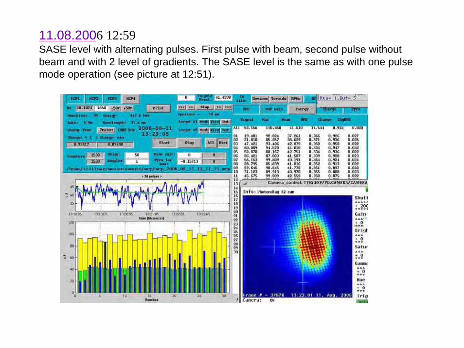
11.08.2006 12:59 SASE level with alternating pulses. First pulse with beam, second pulse without beam and with 2 level of gradients. The SASE level is the same as with one pulse mode operation (see picture at 12:51).

LLRF Development at FLASH, March 29, 2008
LLRF Goals for FLASH in 2008• Install and commission new Master Oscillator• Install redundant LLRF development system in ACC1• Investigate Phase drifts/jumps• Correct problems with ACC1 control• Study RF Gun control limitations• Implement improved user interface for the adaptive
Feedforward• Improve beam loading compensation for all modules• Propose optimum QL for FLASH operation• Design 3.9 GHz LLRF including rf reference for harmonic
cavity• Install redundant ATCA system for ACC456• Install permanent piezo tuning control for ACC 3 5 6• Improve user interface for LLRF operation
LLRF Development at FLASH, March 29, 2008
Some topics for future studies
• Long term beam stability issues • Beam loading effects • RF stability vs. SASE performance • Complete machine stability issue which is
coupled with several RF stations • Control performance of 24 cavities • Improve/automate beam based calibrations
procedures • Exception detection and handling• RF Gun control without probe

LLRF Development at FLASH, March 29, 2008
Shifts required at FLASH
• On average about 1 shift *) / month for the next5 years (about 0.2% of LLRF project effort)
• Topics which require machine studies– ATCA hardware– Transient detection– Beam based feedbacks– Controller– Application development– Cavity resonance control– Automation– Radiation tests
*) Note: Assumes availability of CMTB and developmentssystems (ACC1 and ACC456) in FLASH and parallel studies.