load bearing metal anchors ruumala
TRANSCRIPT
1
2
Content Table
1. U Bar (UB) ..................................................................................................................................... 3
2. Heavy Load U Bar (UB-HL and UB-HLX) ........................................................................................ 6
3. U Bar Angle (UB-A) ....................................................................................................................... 7
4. U Screw Bracket (US-BR) .............................................................................................................. 8
5. UL and UF Bracket (UL-BR and UF-BR)........................................................................................ 10
6. U Flat Hidden Bracket (UF-H) .................................................................................................... 12
7. U Floating Bracket (U-Float) ....................................................................................................... 14
8. UL and UF Heavy Load Bracket (UL-HL BR and UF-HL BR) ......................................................... 16
9. Brick-Perforated Rail (B-PR) ....................................................................................................... 18
10. Brick Static Tube (B-ST) ............................................................................................................ 19
11. Secure Angle (SA) ..................................................................................................................... 20
12. Flat and U Angle (F-A and U-A) ................................................................................................ 22
13. Wall U Angle (WU-A) ............................................................................................................... 24
14. Wall U Angle Adjustable (WUL-A and WUF-A) ........................................................................ 27
15. Floating Angle (WU-Float) ....................................................................................................... 29
16. Double U Angle and Flat Bar U Angle (DU-A and FBU-A) ........................................................ 30
17. Wall Mounting Bracket (WL-MBR and WF-MBR)..................................................................... 32
18. Frame Heavy Load Angle (FR-HL A) ......................................................................................... 34
19. Joist Heavy Load Bracket (J-HL BR) ......................................................................................... 36
20. Joist Heavy Load Bracket with Angle for base profile (J-HL BR-UA) ....................................... 38
21. Base Profile Bracket (BP-BR) .................................................................................................. 40
22. Base Profile Heavy Load Angle (BP-HLA) ................................................................................ 42
23. Adjusting Set (F-AS, L-AS and HBP-AS) ................................................................................... 43
24. Fasteners (screws, dowels) .................................................................................................... 44
25. Force calculation, location of blocks and technical data........................................................ 47
3
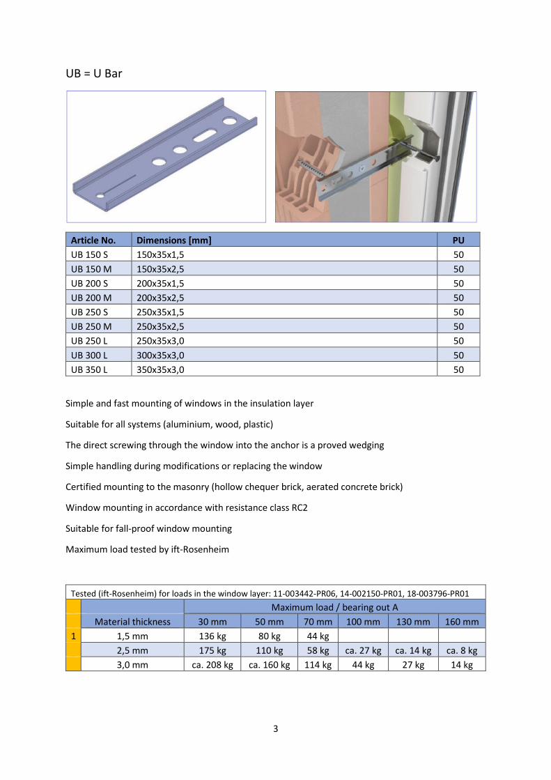
UB = U Bar
Article No. Dimensions [mm] PU
UB 150 S 150x35x1,5 50
UB 150 M 150x35x2,5 50
UB 200 S 200x35x1,5 50
UB 200 M 200x35x2,5 50
UB 250 S 250x35x1,5 50
UB 250 M 250x35x2,5 50
UB 250 L 250x35x3,0 50
UB 300 L 300x35x3,0 50
UB 350 L 350x35x3,0 50
Simple and fast mounting of windows in the insulation layer
Suitable for all systems (aluminium, wood, plastic)
The direct screwing through the window into the anchor is a proved wedging
Simple handling during modifications or replacing the window
Certified mounting to the masonry (hollow chequer brick, aerated concrete brick)
Window mounting in accordance with resistance class RC2
Suitable for fall-proof window mounting
Maximum load tested by ift-Rosenheim
Tested (ift-Rosenheim) for loads in the window layer: 11-003442-PR06, 14-002150-PR01, 18-003796-PR01
Maximum load / bearing out A
Material thickness 30 mm 50 mm 70 mm 100 mm 130 mm 160 mm
1 1,5 mm 136 kg 80 kg 44 kg
2,5 mm 175 kg 110 kg 58 kg ca. 27 kg ca. 14 kg ca. 8 kg
3,0 mm ca. 208 kg ca. 160 kg 114 kg 44 kg 27 kg 14 kg
4
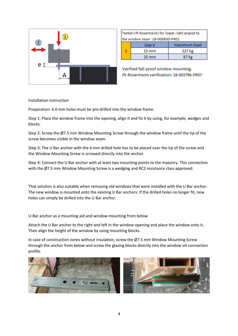
Installation instruction
Preparation: 6.0 mm holes must be pre-drilled into the window frame.
Step 1: Place the window frame into the opening, align it and fix it by using, for example, wedges and
blocks.
Step 2: Screw the Ø7.5 mm Window Mounting Screw through the window frame until the tip of the
screw becomes visible in the window seam.
Step 3: The U Bar anchor with the 6 mm drilled hole has to be placed over the tip of the screw and
the Window Mounting Screw is screwed directly into the anchor.
Step 4: Connect the U Bar anchor with at least two mounting points to the masonry. This connection
with the Ø7.5 mm Window Mounting Screw is a wedging and RC2 resistance class approved.
That solution is also suitable when removing old windows that were installed with the U Bar anchor.
The new window is mounted onto the existing U Bar anchors. If the drilled holes no longer fit, new
holes can simply be drilled into the U Bar anchor.
U-Bar anchor as a mounting aid and window mounting from below
Attach the U Bar anchor to the right and left in the window opening and place the window onto it.
Then align the height of the window by using mounting blocks.
In case of construction zones without insulation, screw the Ø7.5 mm Window Mounting Screw
through the anchor from below and screw the glazing blocks directly into the window sill connection
profile.

5
In case of construction zones with insulation, a connecting angle is used for the connection between
the window and the U Bar anchor. The angle is fixed to the U Bar anchor with two Drilling Screws.
6
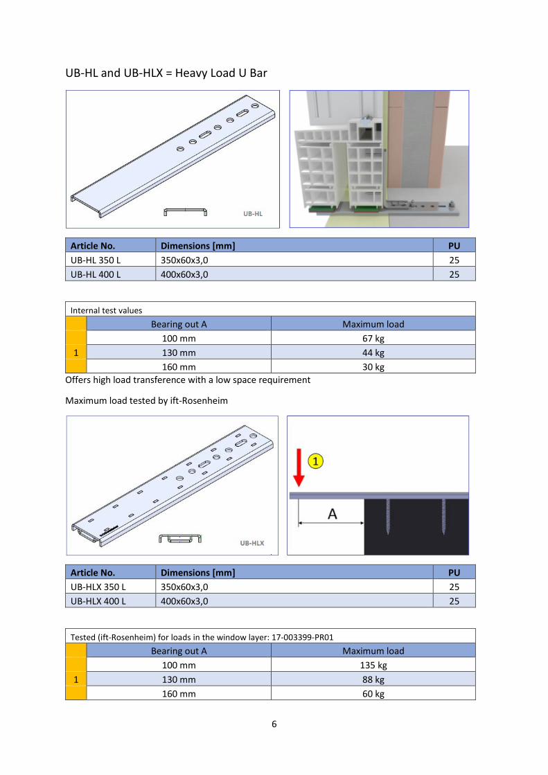
UB-HL and UB-HLX = Heavy Load U Bar
Article No. Dimensions [mm] PU
UB-HL 350 L 350x60x3,0 25
UB-HL 400 L 400x60x3,0 25
Internal test values
Bearing out A Maximum load
100 mm 67 kg
1 130 mm 44 kg
160 mm 30 kg
Offers high load transference with a low space requirement
Maximum load tested by ift-Rosenheim
Article No. Dimensions [mm] PU
UB-HLX 350 L 350x60x3,0 25
UB-HLX 400 L 400x60x3,0 25
Tested (ift-Rosenheim) for loads in the window layer: 17-003399-PR01
Bearing out A Maximum load
100 mm 135 kg
1 130 mm 88 kg
160 mm 60 kg
7
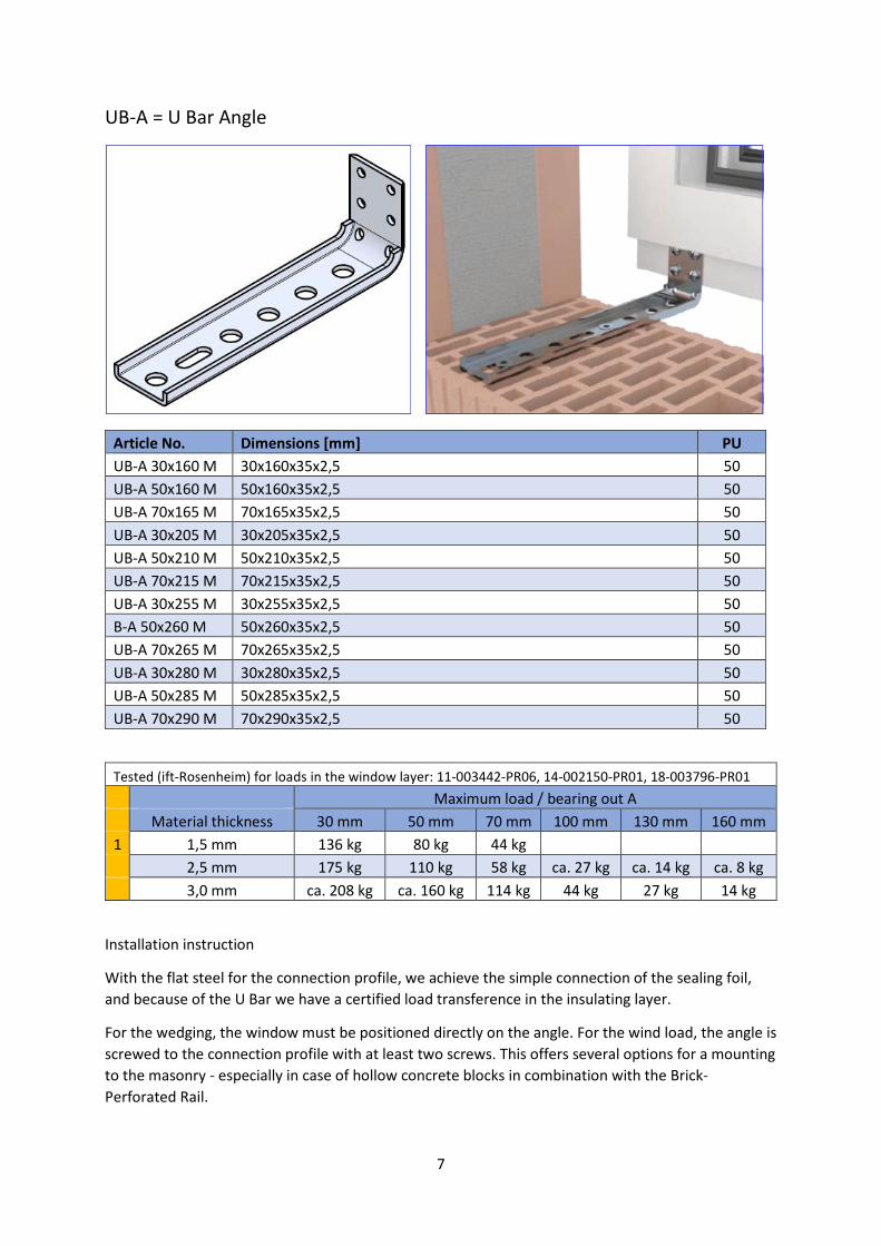
UB-A = U Bar Angle
Article No. Dimensions [mm] PU
UB-A 30x160 M 30x160x35x2,5 50
UB-A 50x160 M 50x160x35x2,5 50
UB-A 70x165 M 70x165x35x2,5 50
UB-A 30x205 M 30x205x35x2,5 50
UB-A 50x210 M 50x210x35x2,5 50
UB-A 70x215 M 70x215x35x2,5 50
UB-A 30x255 M 30x255x35x2,5 50
B-A 50x260 M 50x260x35x2,5 50
UB-A 70x265 M 70x265x35x2,5 50
UB-A 30x280 M 30x280x35x2,5 50
UB-A 50x285 M 50x285x35x2,5 50
UB-A 70x290 M 70x290x35x2,5 50
Tested (ift-Rosenheim) for loads in the window layer: 11-003442-PR06, 14-002150-PR01, 18-003796-PR01
Maximum load / bearing out A
Material thickness 30 mm 50 mm 70 mm 100 mm 130 mm 160 mm
1 1,5 mm 136 kg 80 kg 44 kg
2,5 mm 175 kg 110 kg 58 kg ca. 27 kg ca. 14 kg ca. 8 kg
3,0 mm ca. 208 kg ca. 160 kg 114 kg 44 kg 27 kg 14 kg
Installation instruction
With the flat steel for the connection profile, we achieve the simple connection of the sealing foil,
and because of the U Bar we have a certified load transference in the insulating layer.
For the wedging, the window must be positioned directly on the angle. For the wind load, the angle is
screwed to the connection profile with at least two screws. This offers several options for a mounting
to the masonry - especially in case of hollow concrete blocks in combination with the Brick-
Perforated Rail.
8
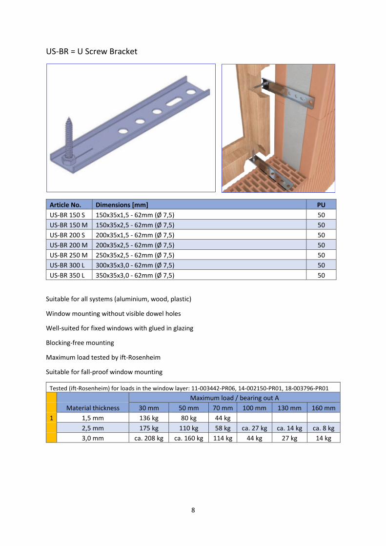
US-BR = U Screw Bracket
Article No. Dimensions [mm] PU
US-BR 150 S 150x35x1,5 - 62mm (Ø 7,5) 50
US-BR 150 M 150x35x2,5 - 62mm (Ø 7,5) 50
US-BR 200 S 200x35x1,5 - 62mm (Ø 7,5) 50
US-BR 200 M 200x35x2,5 - 62mm (Ø 7,5) 50
US-BR 250 M 250x35x2,5 - 62mm (Ø 7,5) 50
US-BR 300 L 300x35x3,0 - 62mm (Ø 7,5) 50
US-BR 350 L 350x35x3,0 - 62mm (Ø 7,5) 50
Suitable for all systems (aluminium, wood, plastic)
Window mounting without visible dowel holes
Well-suited for fixed windows with glued in glazing
Blocking-free mounting
Maximum load tested by ift-Rosenheim
Suitable for fall-proof window mounting
Tested (ift-Rosenheim) for loads in the window layer: 11-003442-PR06, 14-002150-PR01, 18-003796-PR01
Maximum load / bearing out A
Material thickness 30 mm 50 mm 70 mm 100 mm 130 mm 160 mm
1 1,5 mm 136 kg 80 kg 44 kg
2,5 mm 175 kg 110 kg 58 kg ca. 27 kg ca. 14 kg ca. 8 kg
3,0 mm ca. 208 kg ca. 160 kg 114 kg 44 kg 27 kg 14 kg
9
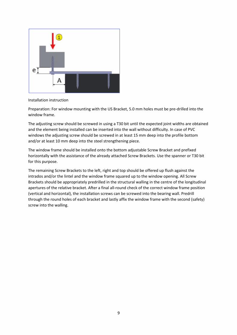
Installation instruction
Preparation: For window mounting with the US Bracket, 5.0 mm holes must be pre-drilled into the
window frame.
The adjusting screw should be screwed in using a T30 bit until the expected joint widths are obtained
and the element being installed can be inserted into the wall without difficulty. In case of PVC
windows the adjusting screw should be screwed in at least 15 mm deep into the profile bottom
and/or at least 10 mm deep into the steel strengthening piece.
The window frame should be installed onto the bottom adjustable Screw Bracket and prefixed
horizontally with the assistance of the already attached Screw Brackets. Use the spanner or T30 bit
for this purpose.
The remaining Screw Brackets to the left, right and top should be offered up flush against the
intrados and/or the lintel and the window frame squared up to the window opening. All Screw
Brackets should be appropriately predrilled in the structural walling in the centre of the longitudinal
apertures of the relative bracket. After a final all-round check of the correct window frame position
(vertical and horizontal), the installation screws can be screwed into the bearing wall. Predrill
through the round holes of each bracket and lastly affix the window frame with the second (safety)
screw into the walling.
10
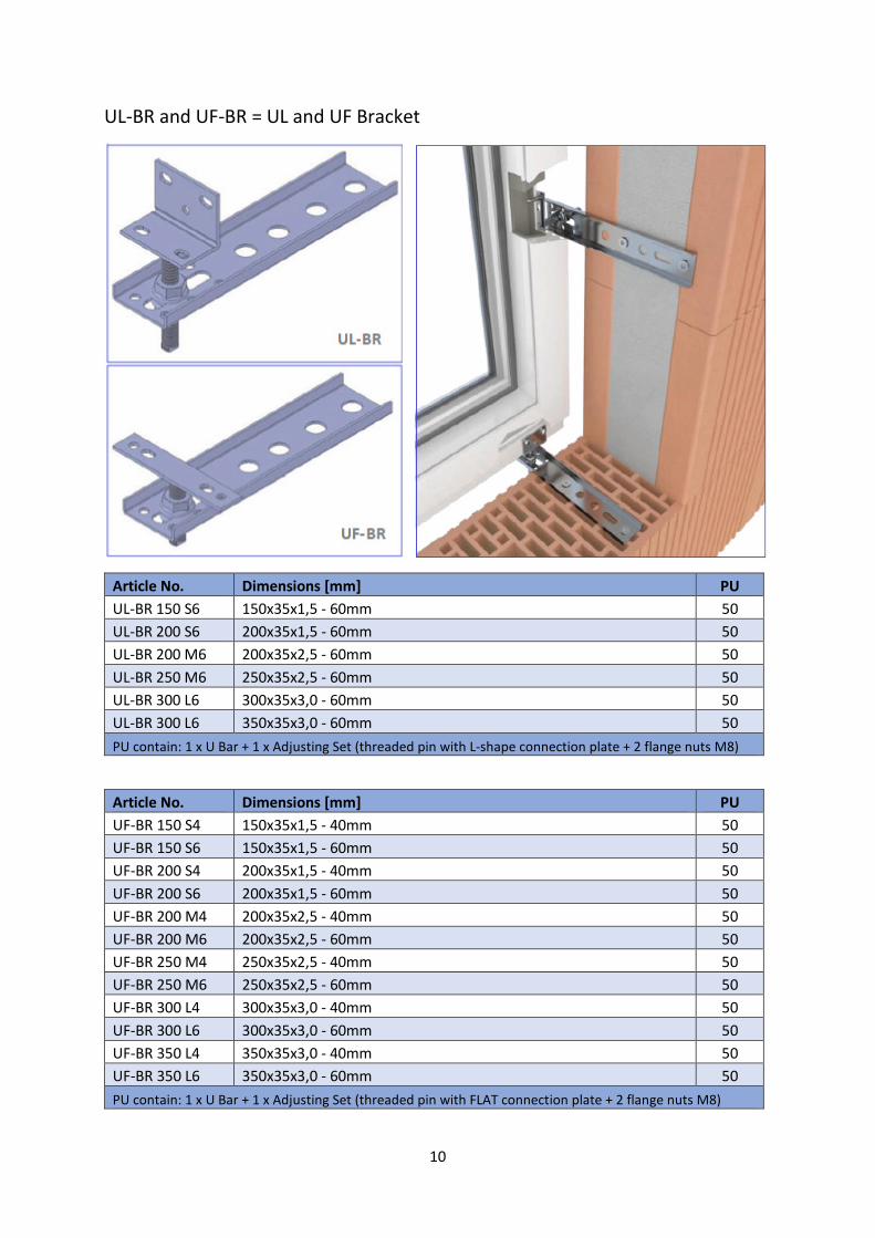
UL-BR and UF-BR = UL and UF Bracket
Article No. Dimensions [mm] PU
UL-BR 150 S6 150x35x1,5 - 60mm 50
UL-BR 200 S6 200x35x1,5 - 60mm 50
UL-BR 200 M6 200x35x2,5 - 60mm 50
UL-BR 250 M6 250x35x2,5 - 60mm 50
UL-BR 300 L6 300x35x3,0 - 60mm 50
UL-BR 300 L6 350x35x3,0 - 60mm 50
PU contain: 1 x U Bar + 1 x Adjusting Set (threaded pin with L-shape connection plate + 2 flange nuts M8)
Article No. Dimensions [mm] PU
UF-BR 150 S4 150x35x1,5 - 40mm 50
UF-BR 150 S6 150x35x1,5 - 60mm 50
UF-BR 200 S4 200x35x1,5 - 40mm 50
UF-BR 200 S6 200x35x1,5 - 60mm 50
UF-BR 200 M4 200x35x2,5 - 40mm 50
UF-BR 200 M6 200x35x2,5 - 60mm 50
UF-BR 250 M4 250x35x2,5 - 40mm 50
UF-BR 250 M6 250x35x2,5 - 60mm 50
UF-BR 300 L4 300x35x3,0 - 40mm 50
UF-BR 300 L6 300x35x3,0 - 60mm 50
UF-BR 350 L4 350x35x3,0 - 40mm 50
UF-BR 350 L6 350x35x3,0 - 60mm 50
PU contain: 1 x U Bar + 1 x Adjusting Set (threaded pin with FLAT connection plate + 2 flange nuts M8)
11
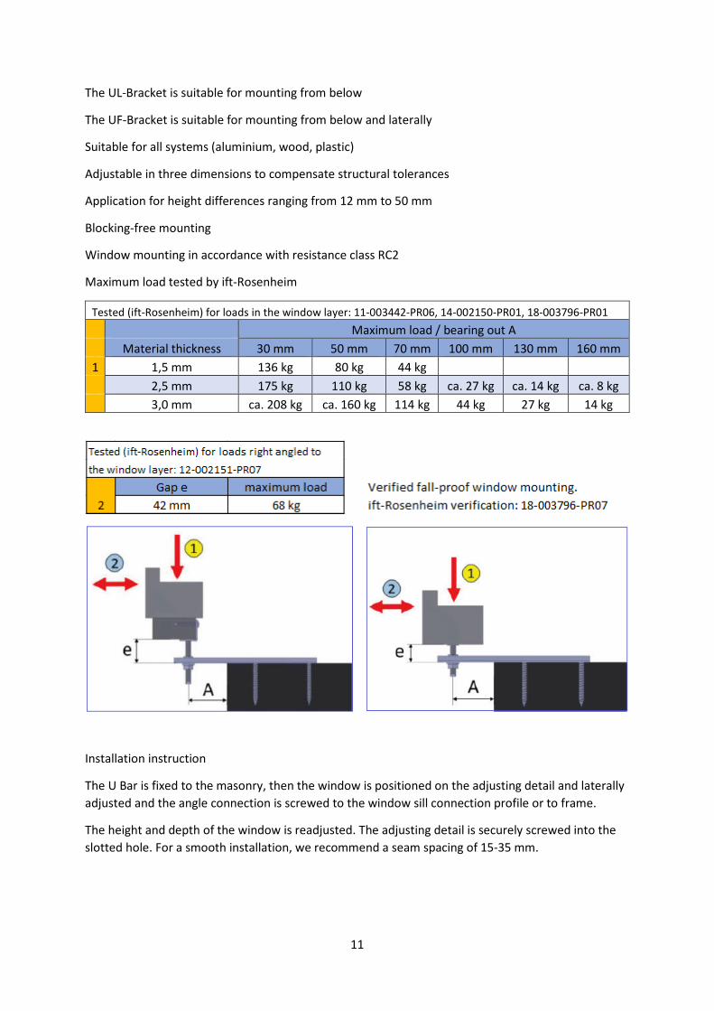
The UL-Bracket is suitable for mounting from below
The UF-Bracket is suitable for mounting from below and laterally
Suitable for all systems (aluminium, wood, plastic)
Adjustable in three dimensions to compensate structural tolerances
Application for height differences ranging from 12 mm to 50 mm
Blocking-free mounting
Window mounting in accordance with resistance class RC2
Maximum load tested by ift-Rosenheim
Tested (ift-Rosenheim) for loads in the window layer: 11-003442-PR06, 14-002150-PR01, 18-003796-PR01
Maximum load / bearing out A
Material thickness 30 mm 50 mm 70 mm 100 mm 130 mm 160 mm
1 1,5 mm 136 kg 80 kg 44 kg
2,5 mm 175 kg 110 kg 58 kg ca. 27 kg ca. 14 kg ca. 8 kg
3,0 mm ca. 208 kg ca. 160 kg 114 kg 44 kg 27 kg 14 kg
Installation instruction
The U Bar is fixed to the masonry, then the window is positioned on the adjusting detail and laterally
adjusted and the angle connection is screwed to the window sill connection profile or to frame.
The height and depth of the window is readjusted. The adjusting detail is securely screwed into the
slotted hole. For a smooth installation, we recommend a seam spacing of 15-35 mm.
12
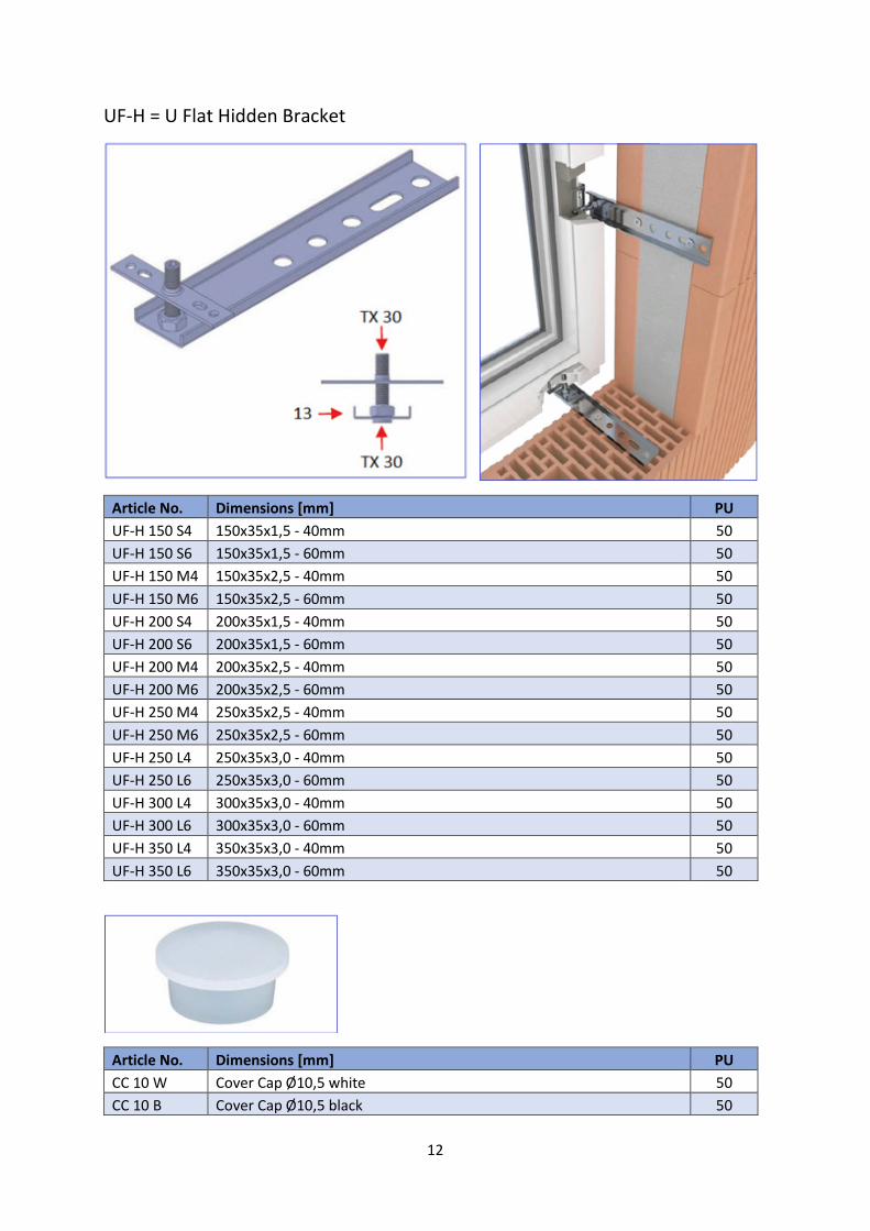
UF-H = U Flat Hidden Bracket
Article No. Dimensions [mm] PU
UF-H 150 S4 150x35x1,5 - 40mm 50
UF-H 150 S6 150x35x1,5 - 60mm 50
UF-H 150 M4 150x35x2,5 - 40mm 50
UF-H 150 M6 150x35x2,5 - 60mm 50
UF-H 200 S4 200x35x1,5 - 40mm 50
UF-H 200 S6 200x35x1,5 - 60mm 50
UF-H 200 M4 200x35x2,5 - 40mm 50
UF-H 200 M6 200x35x2,5 - 60mm 50
UF-H 250 M4 250x35x2,5 - 40mm 50
UF-H 250 M6 250x35x2,5 - 60mm 50
UF-H 250 L4 250x35x3,0 - 40mm 50
UF-H 250 L6 250x35x3,0 - 60mm 50
UF-H 300 L4 300x35x3,0 - 40mm 50
UF-H 300 L6 300x35x3,0 - 60mm 50
UF-H 350 L4 350x35x3,0 - 40mm 50
UF-H 350 L6 350x35x3,0 - 60mm 50
Article No. Dimensions [mm] PU
CC 10 W Cover Cap Ø10,5 white 50
CC 10 B Cover Cap Ø10,5 black 50
13
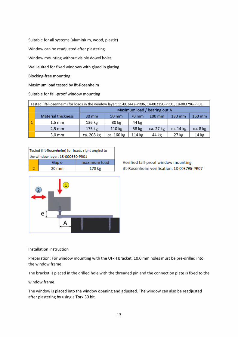
Suitable for all systems (aluminium, wood, plastic)
Window can be readjusted after plastering
Window mounting without visible dowel holes
Well-suited for fixed windows with glued in glazing
Blocking-free mounting
Maximum load tested by ift-Rosenheim
Suitable for fall-proof window mounting
Tested (ift-Rosenheim) for loads in the window layer: 11-003442-PR06, 14-002150-PR01, 18-003796-PR01
Maximum load / bearing out A
Material thickness 30 mm 50 mm 70 mm 100 mm 130 mm 160 mm
1 1,5 mm 136 kg 80 kg 44 kg
2,5 mm 175 kg 110 kg 58 kg ca. 27 kg ca. 14 kg ca. 8 kg
3,0 mm ca. 208 kg ca. 160 kg 114 kg 44 kg 27 kg 14 kg
Installation instruction
Preparation: For window mounting with the UF-H Bracket, 10.0 mm holes must be pre-drilled into
the window frame.
The bracket is placed in the drilled hole with the threaded pin and the connection plate is fixed to the
window frame.
The window is placed into the window opening and adjusted. The window can also be readjusted
after plastering by using a Torx 30 bit.
14
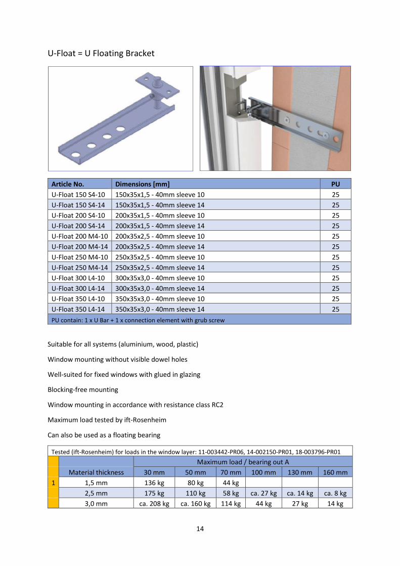
U-Float = U Floating Bracket
Article No. Dimensions [mm] PU
U-Float 150 S4-10 150x35x1,5 - 40mm sleeve 10 25
U-Float 150 S4-14 150x35x1,5 - 40mm sleeve 14 25
U-Float 200 S4-10 200x35x1,5 - 40mm sleeve 10 25
U-Float 200 S4-14 200x35x1,5 - 40mm sleeve 14 25
U-Float 200 M4-10 200x35x2,5 - 40mm sleeve 10 25
U-Float 200 M4-14 200x35x2,5 - 40mm sleeve 14 25
U-Float 250 M4-10 250x35x2,5 - 40mm sleeve 10 25
U-Float 250 M4-14 250x35x2,5 - 40mm sleeve 14 25
U-Float 300 L4-10 300x35x3,0 - 40mm sleeve 10 25
U-Float 300 L4-14 300x35x3,0 - 40mm sleeve 14 25
U-Float 350 L4-10 350x35x3,0 - 40mm sleeve 10 25
U-Float 350 L4-14 350x35x3,0 - 40mm sleeve 14 25
PU contain: 1 x U Bar + 1 x connection element with grub screw
Suitable for all systems (aluminium, wood, plastic)
Window mounting without visible dowel holes
Well-suited for fixed windows with glued in glazing
Blocking-free mounting
Window mounting in accordance with resistance class RC2
Maximum load tested by ift-Rosenheim
Can also be used as a floating bearing
Tested (ift-Rosenheim) for loads in the window layer: 11-003442-PR06, 14-002150-PR01, 18-003796-PR01
Maximum load / bearing out A
Material thickness 30 mm 50 mm 70 mm 100 mm 130 mm 160 mm
1 1,5 mm 136 kg 80 kg 44 kg
2,5 mm 175 kg 110 kg 58 kg ca. 27 kg ca. 14 kg ca. 8 kg
3,0 mm ca. 208 kg ca. 160 kg 114 kg 44 kg 27 kg 14 kg

15
Installation instruction
For frame profiles with indentations, the 14 mm sleeve has to be selected in order that the grub
screw can be reached. In case of profiles without indentations, the 10 mm sleeve will suffice.
Preparation: For window mounting with the U Floating Bracket, the frame has to be drilled out with
10.0 mm holes merely from behind. Therefore, the hole is not visible from inside.
The connection element is secured in such a way that the pin can be inserted into the frame hole.
Using the guide sleeve and the pin, the window can be infinitly adjusted. The wedging is possible via
using the grub screw and it is RC2-certified.
16
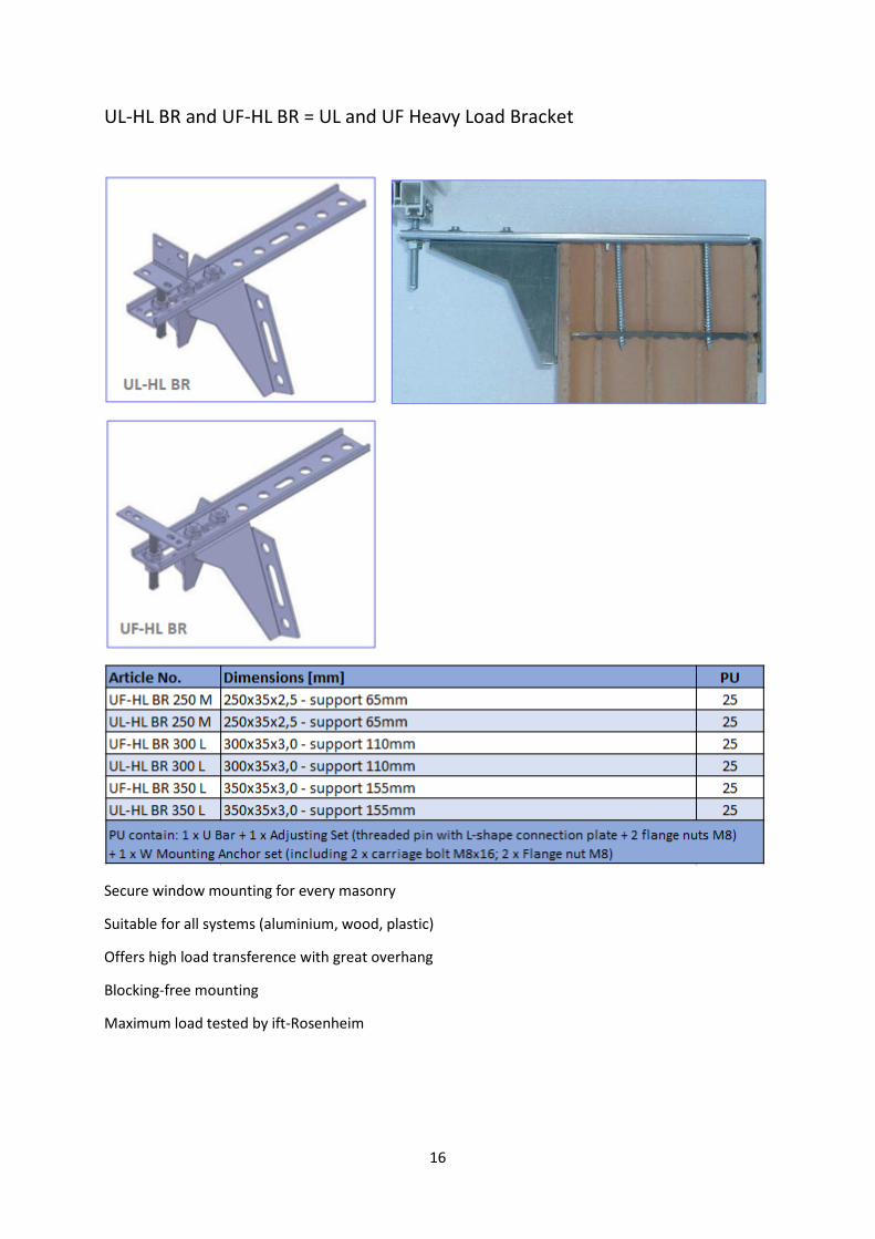
UL-HL BR and UF-HL BR = UL and UF Heavy Load Bracket
Secure window mounting for every masonry
Suitable for all systems (aluminium, wood, plastic)
Offers high load transference with great overhang
Blocking-free mounting
Maximum load tested by ift-Rosenheim
17
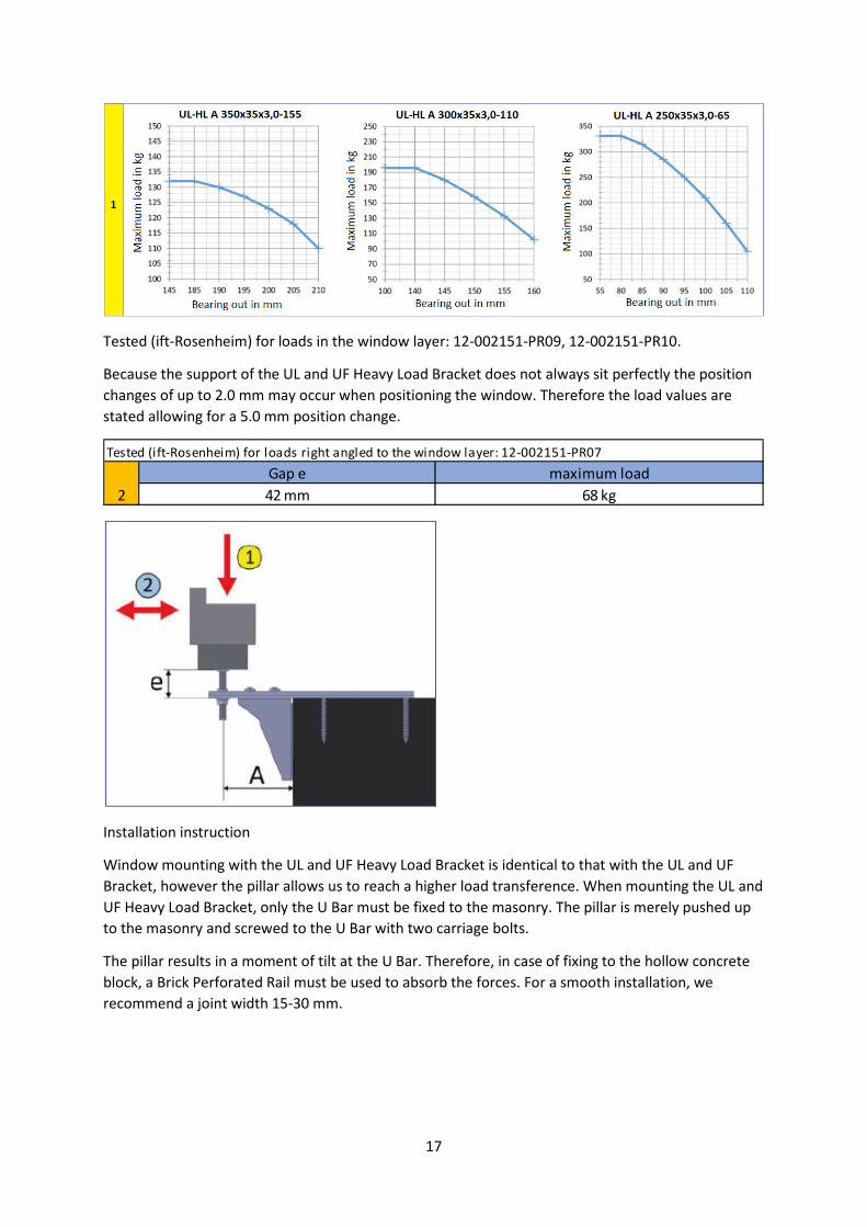
Tested (ift-Rosenheim) for loads in the window layer: 12-002151-PR09, 12-002151-PR10.
Because the support of the UL and UF Heavy Load Bracket does not always sit perfectly the position
changes of up to 2.0 mm may occur when positioning the window. Therefore the load values are
stated allowing for a 5.0 mm position change.
Installation instruction
Window mounting with the UL and UF Heavy Load Bracket is identical to that with the UL and UF
Bracket, however the pillar allows us to reach a higher load transference. When mounting the UL and
UF Heavy Load Bracket, only the U Bar must be fixed to the masonry. The pillar is merely pushed up
to the masonry and screwed to the U Bar with two carriage bolts.
The pillar results in a moment of tilt at the U Bar. Therefore, in case of fixing to the hollow concrete
block, a Brick Perforated Rail must be used to absorb the forces. For a smooth installation, we
recommend a joint width 15-30 mm.
Gap e maximum load
2 42 mm 68 kg
Tested (ift-Rosenheim) for loads right angled to the window layer: 12-002151-PR07
18
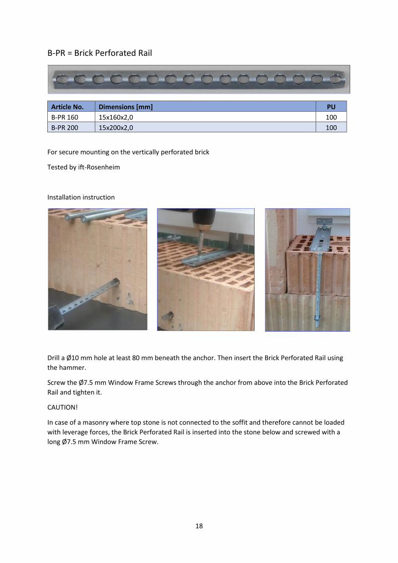
B-PR = Brick Perforated Rail
Article No. Dimensions [mm] PU
B-PR 160 15x160x2,0 100
B-PR 200 15x200x2,0 100
For secure mounting on the vertically perforated brick
Tested by ift-Rosenheim
Installation instruction
Drill a Ø10 mm hole at least 80 mm beneath the anchor. Then insert the Brick Perforated Rail using
the hammer.
Screw the Ø7.5 mm Window Frame Screws through the anchor from above into the Brick Perforated
Rail and tighten it.
CAUTION!
In case of a masonry where top stone is not connected to the soffit and therefore cannot be loaded
with leverage forces, the Brick Perforated Rail is inserted into the stone below and screwed with a
long Ø7.5 mm Window Frame Screw.
19
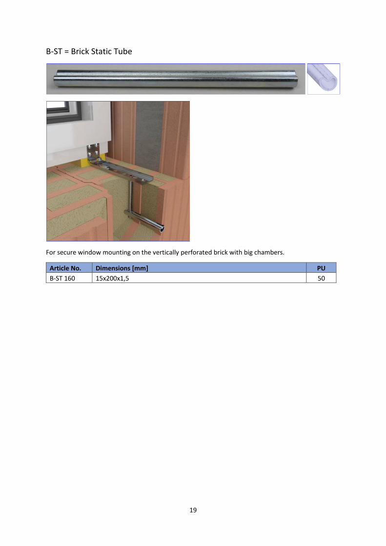
B-ST = Brick Static Tube
For secure window mounting on the vertically perforated brick with big chambers.
Article No. Dimensions [mm] PU
B-ST 160 15x200x1,5 50
20
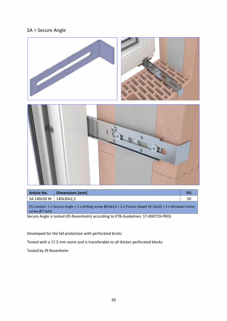
SA = Secure Angle
Article No. Dimensions [mm] PU
SA 140x30 M 140x30x2,5 50
PU contain: 1 x Secure Angle + 2 x drilling screw Ø4,8x13 + 2 x Fischer dowel SX 10x50 + 2 x Window Frame
screw Ø7.5x42
Secure Angle is tested (ift-Rosenheim) according to ETB-Guidelines: 17-000719-PR03
Developed for the fall protection with perforated bricks
Tested with a 17.5 mm stone and is transferable to all thicker perforated blocks
Tested by ift-Rosenheim
21
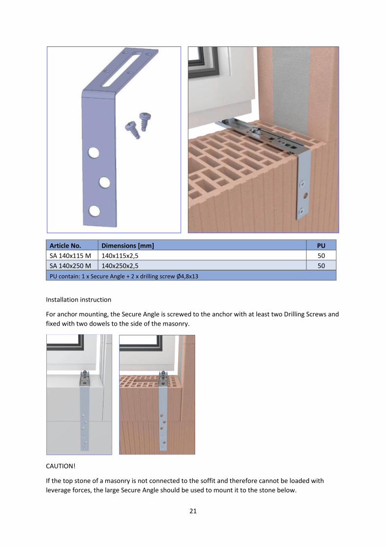
Article No. Dimensions [mm] PU
SA 140x115 M 140x115x2,5 50
SA 140x250 M 140x250x2,5 50
PU contain: 1 x Secure Angle + 2 x drilling screw Ø4,8x13
Installation instruction
For anchor mounting, the Secure Angle is screwed to the anchor with at least two Drilling Screws and
fixed with two dowels to the side of the masonry.
CAUTION!
If the top stone of a masonry is not connected to the soffit and therefore cannot be loaded with
leverage forces, the large Secure Angle should be used to mount it to the stone below.

22
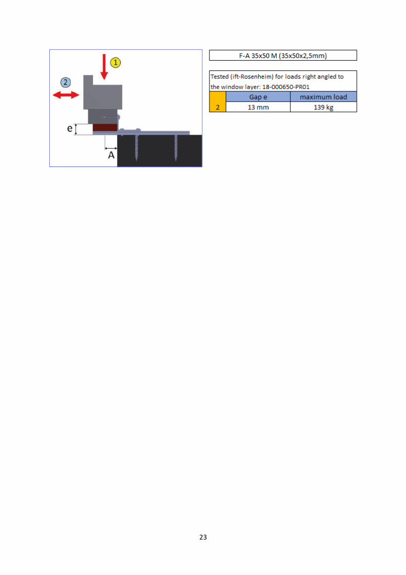
F-A and U-A = Flat and U Angle (in combination with other products)
Article No. Dimensions [mm] PU
F-A 35x50 M 35x50x2,5 (flat steel) 50
U-A 65x95 M 65x95x2,5 50
U-A 65x145 M 65x145x2,5 50
U-A 65x170 M 65x170x2,5 50
U-A 95x140 L 95x140x3,0 50
U-A 110x125 L 110x125x3,0 50
U-A 110x150 L 110x150x3,0 50
PU contain: 1 x F or U Angle + 2 x drilling screw Ø4,8x13
For the connection of window and mounting anchor
For the bracing of balcony connection profiles
Suitable for fall-proof window mounting
Tested (ift-Rosenheim) for loads in the window layer: 11-003442-PR06, 14-002150-PR01, 18-003796-PR01
Maximum load / bearing out A
Material thickness 30 mm 50 mm 70 mm 100 mm 130 mm 160 mm
1 1,5 mm 136 kg 80 kg 44 kg
2,5 mm 175 kg 110 kg 58 kg ca. 27 kg ca. 14 kg ca. 8 kg
3,0 mm ca. 208 kg ca. 160 kg 114 kg 44 kg 27 kg 14 kg
23
24
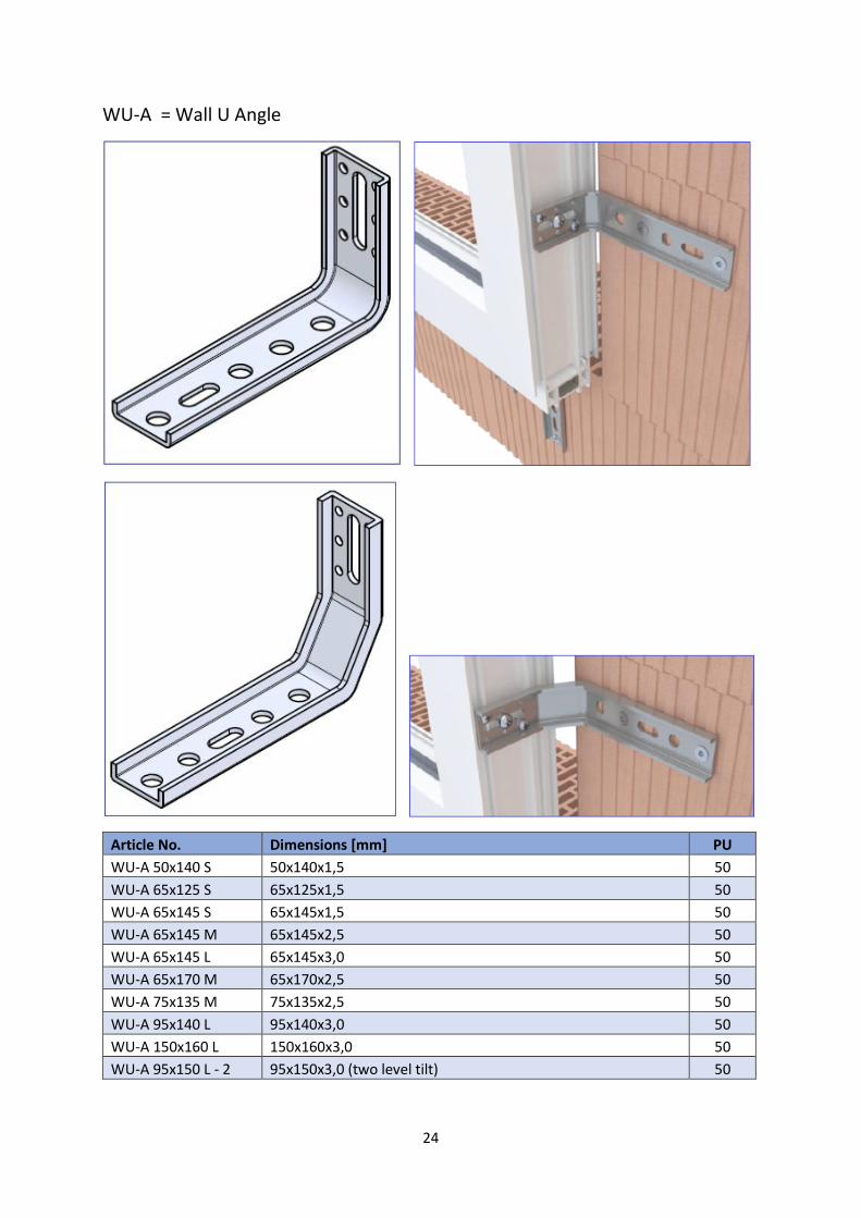
WU-A = Wall U Angle
Article No. Dimensions [mm] PU
WU-A 50x140 S 50x140x1,5 50
WU-A 65x125 S 65x125x1,5 50
WU-A 65x145 S 65x145x1,5 50
WU-A 65x145 M 65x145x2,5 50
WU-A 65x145 L 65x145x3,0 50
WU-A 65x170 M 65x170x2,5 50
WU-A 75x135 M 75x135x2,5 50
WU-A 95x140 L 95x140x3,0 50
WU-A 150x160 L 150x160x3,0 50
WU-A 95x150 L - 2 95x150x3,0 (two level tilt) 50

25
Tested (ift-Rosenheim) for load transference according to ETB-Guidelines: 17-000719-PR02, 18-
000732-PR02
Tested (ift-Rosenheim) for loads in the window layer: 11-003442-PR06, 12-002151-PR04,
14-002150-PR02, 17-001190-PR01
Material Maximum load / bearing out A
thickness 25 mm 35 mm 40 mm 55 mm 57 mm 60 mm 87 mm
1 1,5 mm 212 kg ca. 110 kg 45 kg ca. 40 kg 38 kg
2,5 mm min 212 kg 170 kg ca. 140 kg ca. 68 kg ca. 60 kg ca. 50 kg 34 kg
3,0 mm min 347 kg 347 kg ca. 270 kg 147 kg ca. 143 kg 139 kg 66 kg
Simple and fast mounting of windows inside the insulating layer
Suitable for all systems (aluminium, wood, plastic)
Short leg for mounting to the window frame, long leg for mounting to the masonry
Two-level tilt for more leeway for the sealing
Window mounting in accordance with resistance class RC2
Suitable for fall-proof window mounting
Maximum load tested by ift-Rosenheim

26
Installation instruction
The Wall U Angle (WU-A) is first screwed to the window frame through the slotted hole using a
Ø7.5x42 mm Window Frame Screw.
The frame is placed on the bottom amount or on the Window Mounting Clamps and the height is
aligned.
The window WU Angle is fixed to the masonry.
The fine adjustment of the depth is realised via the slotted hole. To secure the configuration, the
screw is tightened to the window and fixed with additional screws through the holes.
27
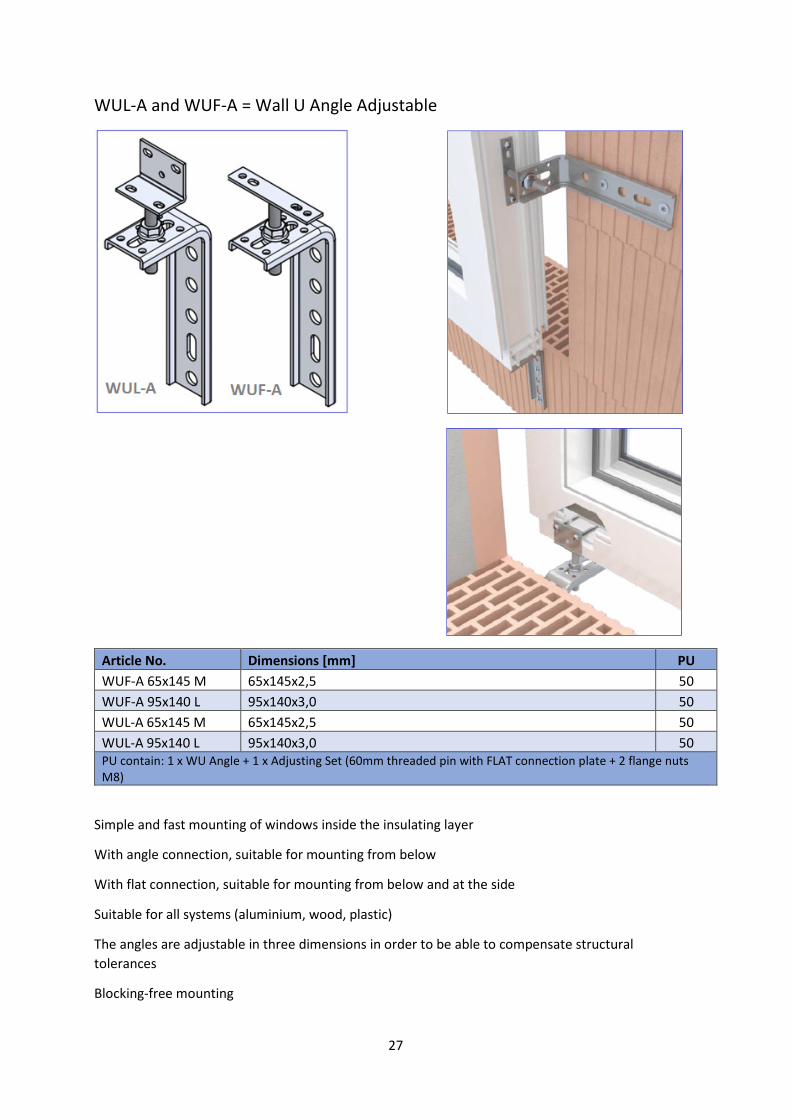
WUL-A and WUF-A = Wall U Angle Adjustable
Article No. Dimensions [mm] PU
WUF-A 65x145 M 65x145x2,5 50
WUF-A 95x140 L 95x140x3,0 50
WUL-A 65x145 M 65x145x2,5 50
WUL-A 95x140 L 95x140x3,0 50
PU contain: 1 x WU Angle + 1 x Adjusting Set (60mm threaded pin with FLAT connection plate + 2 flange nuts
M8)
Simple and fast mounting of windows inside the insulating layer
With angle connection, suitable for mounting from below
With flat connection, suitable for mounting from below and at the side
Suitable for all systems (aluminium, wood, plastic)
The angles are adjustable in three dimensions in order to be able to compensate structural
tolerances
Blocking-free mounting
28
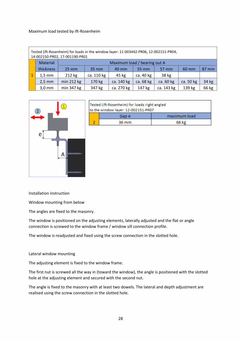
Maximum load tested by ift-Rosenheim
Tested (ift-Rosenheim) for loads in the window layer: 11-003442-PR06, 12-002151-PR04,
14-002150-PR02, 17-001190-PR01
Material Maximum load / bearing out A
thickness 25 mm 35 mm 40 mm 55 mm 57 mm 60 mm 87 mm
1 1,5 mm 212 kg ca. 110 kg 45 kg ca. 40 kg 38 kg
2,5 mm min 212 kg 170 kg ca. 140 kg ca. 68 kg ca. 60 kg ca. 50 kg 34 kg
3,0 mm min 347 kg 347 kg ca. 270 kg 147 kg ca. 143 kg 139 kg 66 kg
Installation instruction
Window mounting from below
The angles are fixed to the masonry.
The window is positioned on the adjusting elements, laterally adjusted and the flat or angle
connection is screwed to the window frame / window sill connection profile.
The window is readjusted and fixed using the screw connection in the slotted hole.
Lateral window mounting
The adjusting element is fixed to the window frame.
The first nut is screwed all the way in (toward the window), the angle is positioned with the slotted
hole at the adjusting element and secured with the second nut.
The angle is fixed to the masonry with at least two dowels. The lateral and depth adjustment are
realised using the screw connection in the slotted hole.
29
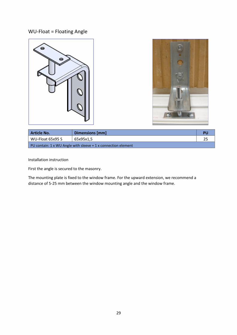
WU-Float = Floating Angle
Article No. Dimensions [mm] PU
WU-Float 65x95 S 65x95x1,5 25
PU contain: 1 x WU Angle with sleeve + 1 x connection element
Installation instruction
First the angle is secured to the masonry.
The mounting plate is fixed to the window frame. For the upward extension, we recommend a
distance of 5-25 mm between the window mounting angle and the window frame.
30
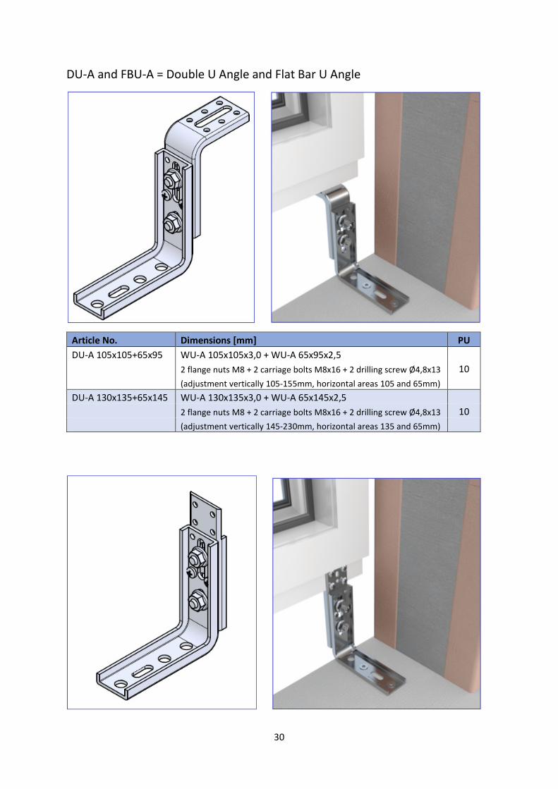
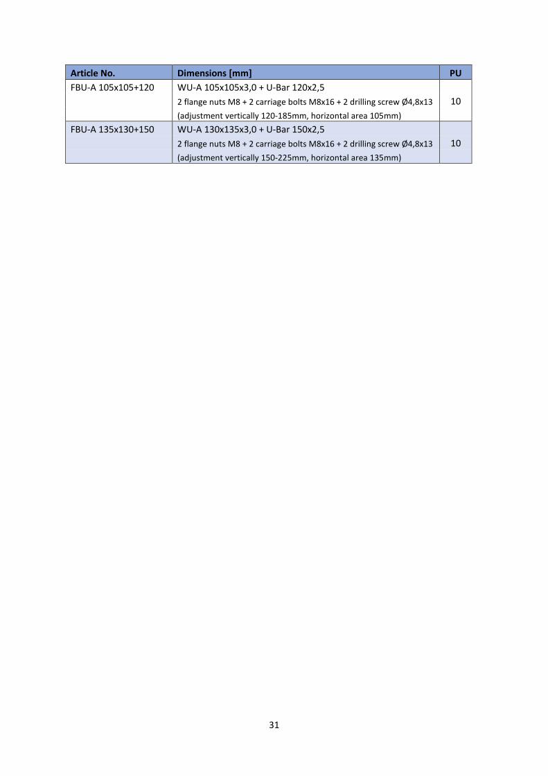
DU-A and FBU-A = Double U Angle and Flat Bar U Angle
Article No. Dimensions [mm] PU
DU-A 105x105+65x95 WU-A 105x105x3,0 + WU-A 65x95x2,5
2 flange nuts M8 + 2 carriage bolts M8x16 + 2 drilling screw Ø4,8x13 10
(adjustment vertically 105-155mm, horizontal areas 105 and 65mm)
DU-A 130x135+65x145 WU-A 130x135x3,0 + WU-A 65x145x2,5
2 flange nuts M8 + 2 carriage bolts M8x16 + 2 drilling screw Ø4,8x13 10
(adjustment vertically 145-230mm, horizontal areas 135 and 65mm)
31
Article No. Dimensions [mm] PU
FBU-A 105x105+120 WU-A 105x105x3,0 + U-Bar 120x2,5
2 flange nuts M8 + 2 carriage bolts M8x16 + 2 drilling screw Ø4,8x13 10
(adjustment vertically 120-185mm, horizontal area 105mm)
FBU-A 135x130+150 WU-A 130x135x3,0 + U-Bar 150x2,5
2 flange nuts M8 + 2 carriage bolts M8x16 + 2 drilling screw Ø4,8x13 10
(adjustment vertically 150-225mm, horizontal area 135mm)
32
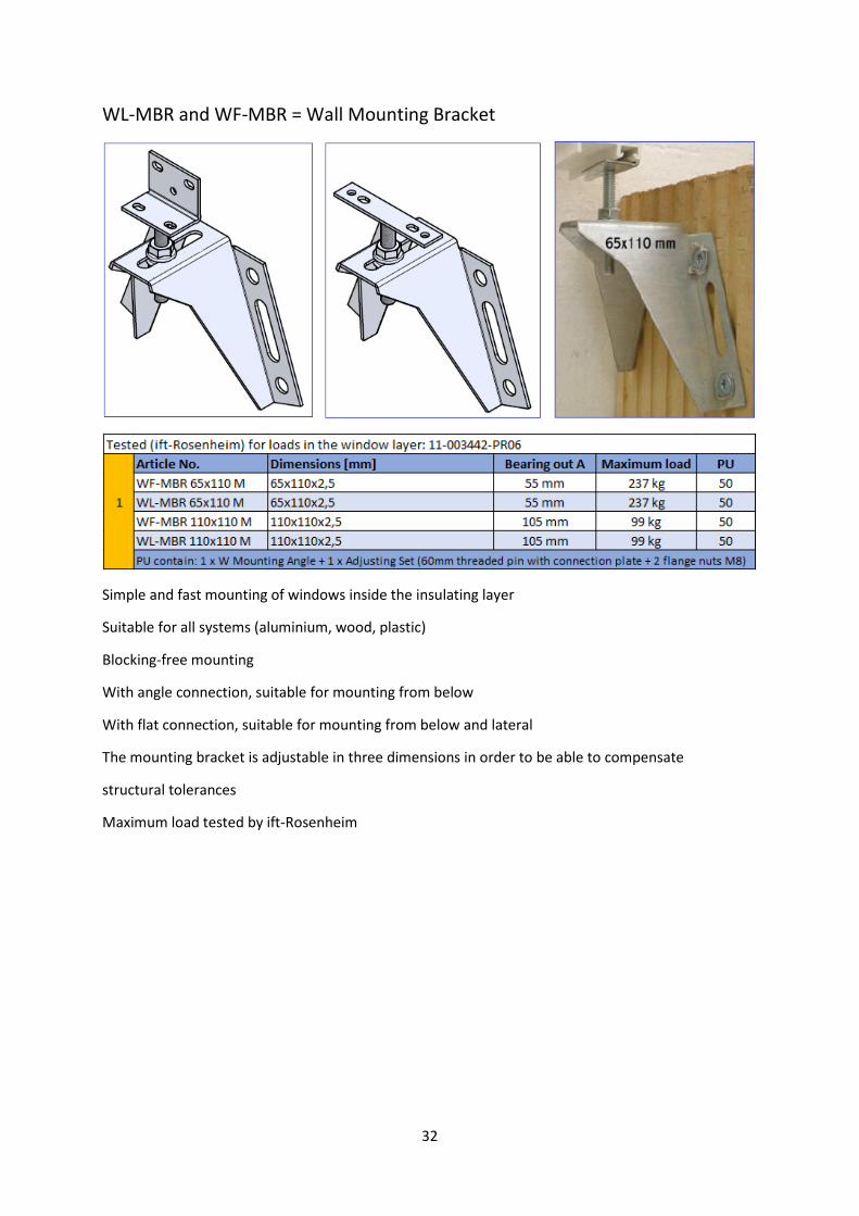
WL-MBR and WF-MBR = Wall Mounting Bracket
Simple and fast mounting of windows inside the insulating layer
Suitable for all systems (aluminium, wood, plastic)
Blocking-free mounting
With angle connection, suitable for mounting from below
With flat connection, suitable for mounting from below and lateral
The mounting bracket is adjustable in three dimensions in order to be able to compensate
structural tolerances
Maximum load tested by ift-Rosenheim
33
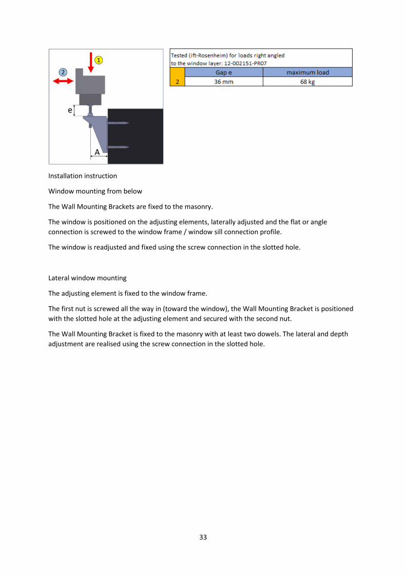
Installation instruction
Window mounting from below
The Wall Mounting Brackets are fixed to the masonry.
The window is positioned on the adjusting elements, laterally adjusted and the flat or angle
connection is screwed to the window frame / window sill connection profile.
The window is readjusted and fixed using the screw connection in the slotted hole.
Lateral window mounting
The adjusting element is fixed to the window frame.
The first nut is screwed all the way in (toward the window), the Wall Mounting Bracket is positioned
with the slotted hole at the adjusting element and secured with the second nut.
The Wall Mounting Bracket is fixed to the masonry with at least two dowels. The lateral and depth
adjustment are realised using the screw connection in the slotted hole.
34
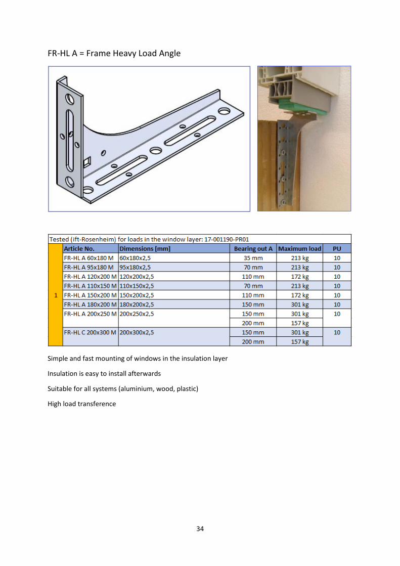
FR-HL A = Frame Heavy Load Angle
Simple and fast mounting of windows in the insulation layer
Insulation is easy to install afterwards
Suitable for all systems (aluminium, wood, plastic)
High load transference
35
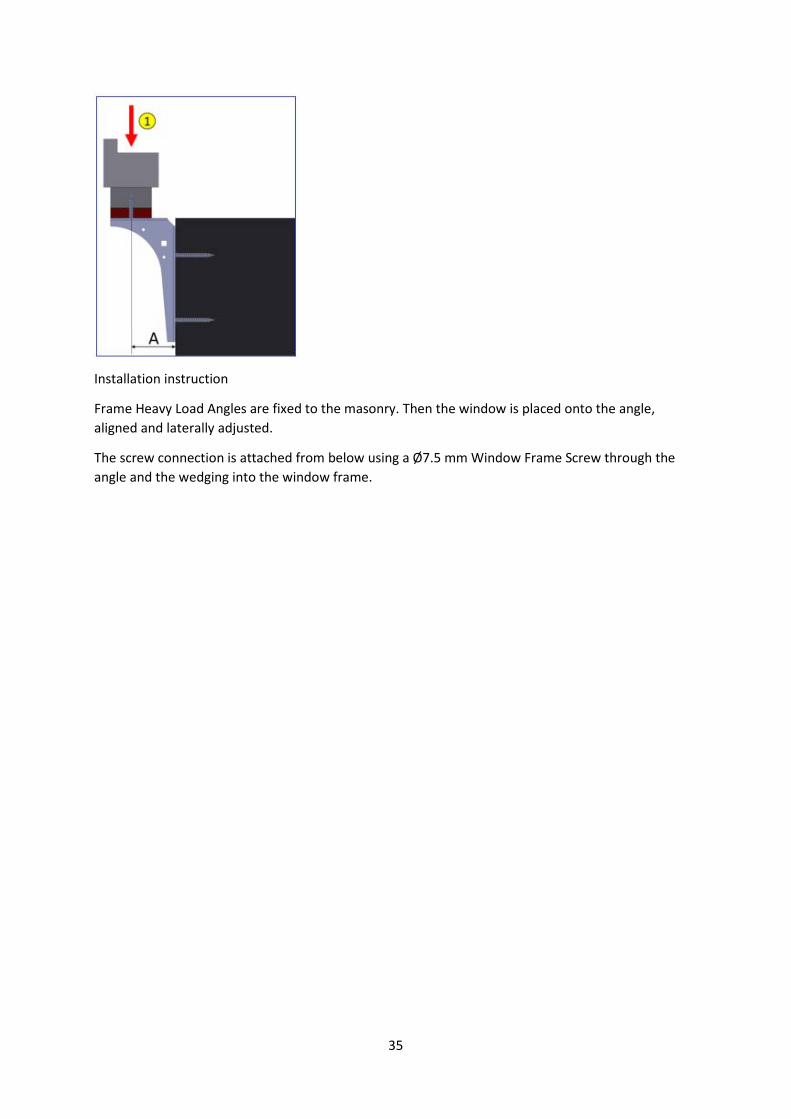
Installation instruction
Frame Heavy Load Angles are fixed to the masonry. Then the window is placed onto the angle,
aligned and laterally adjusted.
The screw connection is attached from below using a Ø7.5 mm Window Frame Screw through the
angle and the wedging into the window frame.
36
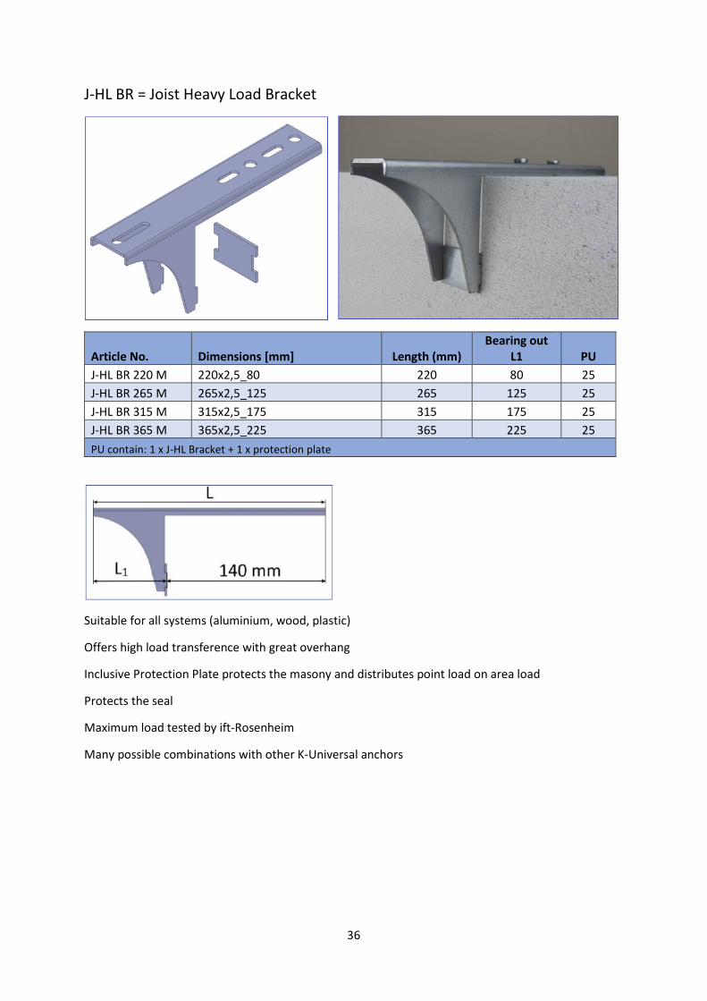
J-HL BR = Joist Heavy Load Bracket
Article No. Dimensions [mm] Length (mm)
Bearing out
L1 PU
J-HL BR 220 M 220x2,5_80 220 80 25
J-HL BR 265 M 265x2,5_125 265 125 25
J-HL BR 315 M 315x2,5_175 315 175 25
J-HL BR 365 M 365x2,5_225 365 225 25
PU contain: 1 x J-HL Bracket + 1 x protection plate
Suitable for all systems (aluminium, wood, plastic)
Offers high load transference with great overhang
Inclusive Protection Plate protects the masony and distributes point load on area load
Protects the seal
Maximum load tested by ift-Rosenheim
Many possible combinations with other K-Universal anchors
37
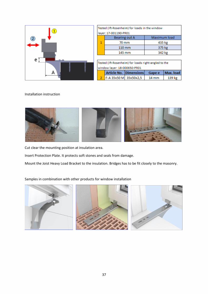
Installation instruction
Cut clear the mounting position at insulation area.
Insert Protection Plate. It protects soft stones and seals from damage.
Mount the Joist Heavy Load Bracket to the insulation. Bridges has to be fit closely to the masonry.
Samples in combination with other products for window installation
38
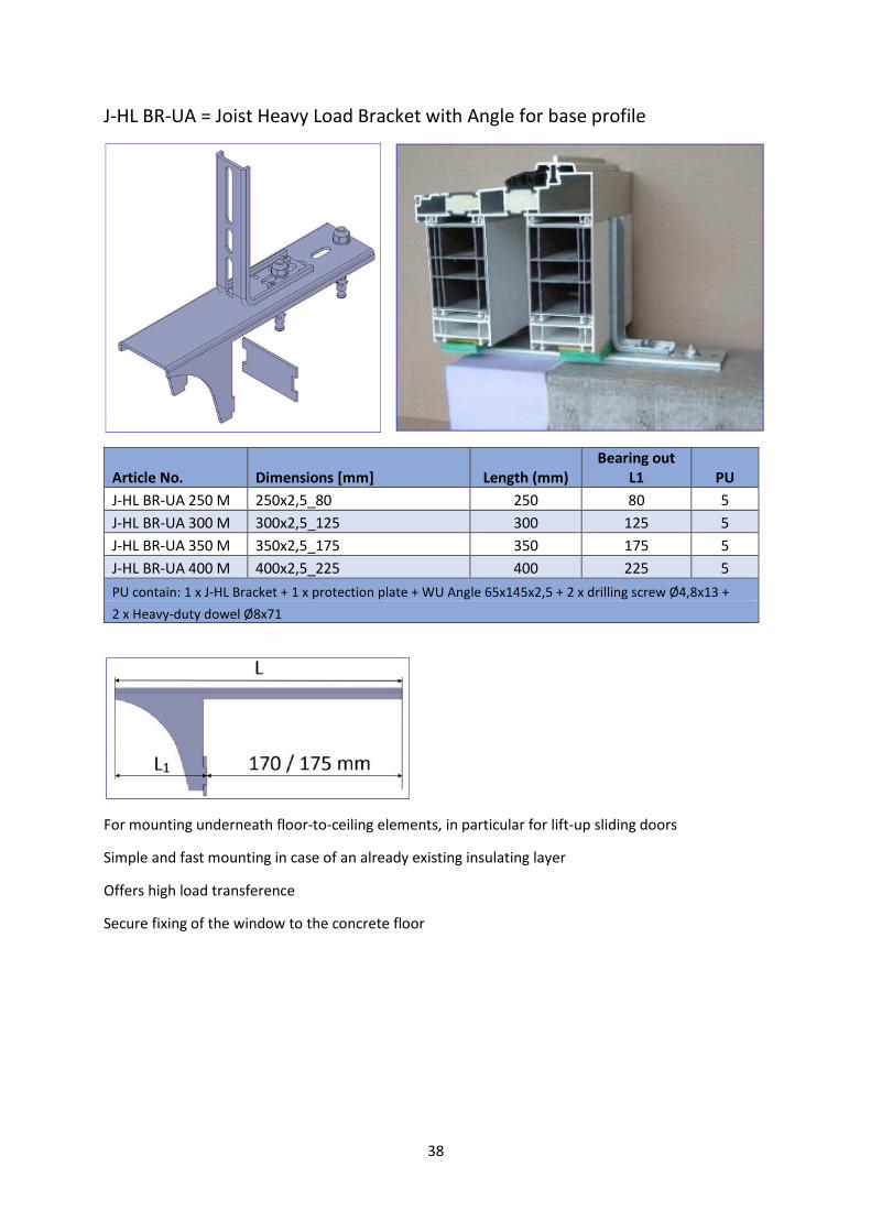
J-HL BR-UA = Joist Heavy Load Bracket with Angle for base profile
Article No. Dimensions [mm] Length (mm)
Bearing out
L1 PU
J-HL BR-UA 250 M 250x2,5_80 250 80 5
J-HL BR-UA 300 M 300x2,5_125 300 125 5
J-HL BR-UA 350 M 350x2,5_175 350 175 5
J-HL BR-UA 400 M 400x2,5_225 400 225 5
PU contain: 1 x J-HL Bracket + 1 x protection plate + WU Angle 65x145x2,5 + 2 x drilling screw Ø4,8x13 +
2 x Heavy-duty dowel Ø8x71
For mounting underneath floor-to-ceiling elements, in particular for lift-up sliding doors
Simple and fast mounting in case of an already existing insulating layer
Offers high load transference
Secure fixing of the window to the concrete floor
39
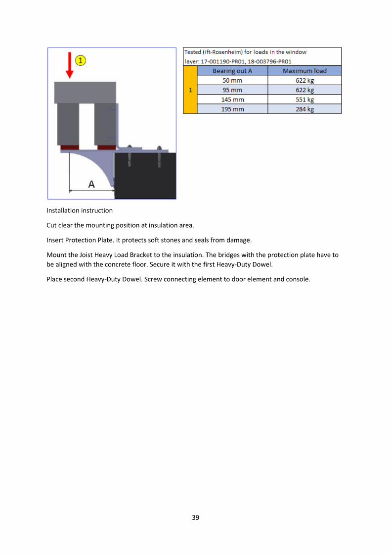
Installation instruction
Cut clear the mounting position at insulation area.
Insert Protection Plate. It protects soft stones and seals from damage.
Mount the Joist Heavy Load Bracket to the insulation. The bridges with the protection plate have to
be aligned with the concrete floor. Secure it with the first Heavy-Duty Dowel.
Place second Heavy-Duty Dowel. Screw connecting element to door element and console.
40
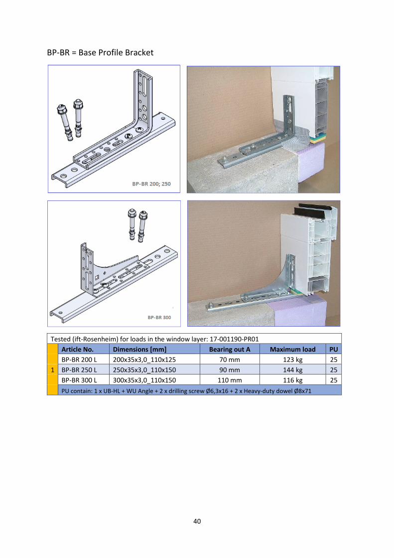
BP-BR = Base Profile Bracket
Tested (ift-Rosenheim) for loads in the window layer: 17-001190-PR01
Article No. Dimensions [mm] Bearing out A Maximum load PU
BP-BR 200 L 200x35x3,0_110x125 70 mm 123 kg 25
1 BP-BR 250 L 250x35x3,0_110x150 90 mm 144 kg 25
BP-BR 300 L 300x35x3,0_110x150 110 mm 116 kg 25
PU contain: 1 x UB-HL + WU Angle + 2 x drilling screw Ø6,3x16 + 2 x Heavy-duty dowel Ø8x71
41
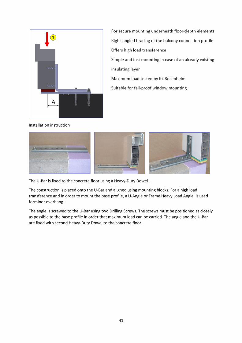
Installation instruction
The U-Bar is fixed to the concrete floor using a Heavy-Duty Dowel .
The construction is placed onto the U-Bar and aligned using mounting blocks. For a high load
transference and in order to mount the base profile, a U-Angle or Frame Heavy Load Angle is used
forminor overhang.
The angle is screwed to the U-Bar using two Drilling Screws. The screws must be positioned as closely
as possible to the base profile in order that maximum load can be carried. The angle and the U-Bar
are fixed with second Heavy-Duty Dowel to the concrete floor.
42
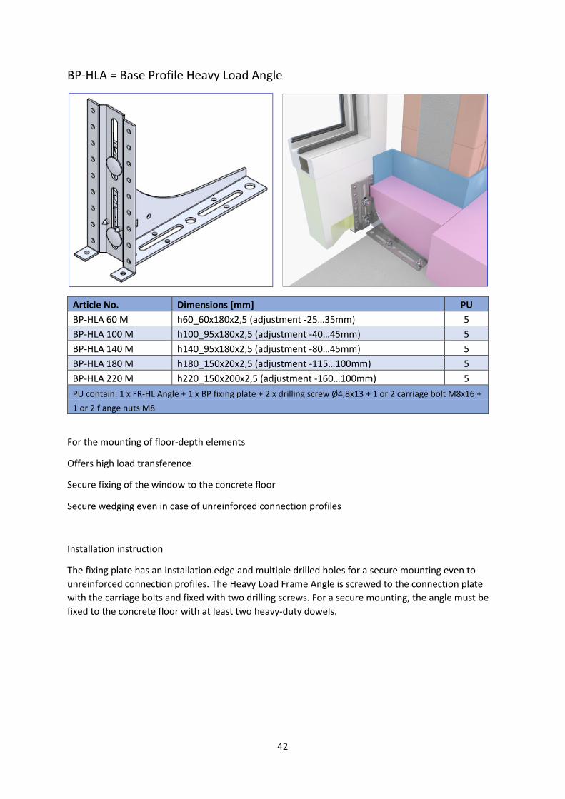
BP-HLA = Base Profile Heavy Load Angle
Article No. Dimensions [mm] PU
BP-HLA 60 M h60_60x180x2,5 (adjustment -25…35mm) 5
BP-HLA 100 M h100_95x180x2,5 (adjustment -40…45mm) 5
BP-HLA 140 M h140_95x180x2,5 (adjustment -80…45mm) 5
BP-HLA 180 M h180_150x20x2,5 (adjustment -115…100mm) 5
BP-HLA 220 M h220_150x200x2,5 (adjustment -160…100mm) 5
PU contain: 1 x FR-HL Angle + 1 x BP fixing plate + 2 x drilling screw Ø4,8x13 + 1 or 2 carriage bolt M8x16 +
1 or 2 flange nuts M8
For the mounting of floor-depth elements
Offers high load transference
Secure fixing of the window to the concrete floor
Secure wedging even in case of unreinforced connection profiles
Installation instruction
The fixing plate has an installation edge and multiple drilled holes for a secure mounting even to
unreinforced connection profiles. The Heavy Load Frame Angle is screwed to the connection plate
with the carriage bolts and fixed with two drilling screws. For a secure mounting, the angle must be
fixed to the concrete floor with at least two heavy-duty dowels.
43
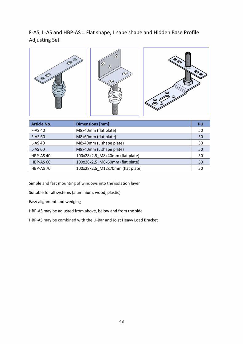
F-AS, L-AS and HBP-AS = Flat shape, L sape shape and Hidden Base Profile
Adjusting Set
Article No. Dimensions [mm] PU
F-AS 40 M8x40mm (flat plate) 50
F-AS 60 M8x60mm (flat plate) 50
L-AS 40 M8x40mm (L shape plate) 50
L-AS 60 M8x40mm (L shape plate) 50
HBP-AS 40 100x28x2,5_M8x40mm (flat plate) 50
HBP-AS 60 100x28x2,5_M8x60mm (flat plate) 50
HBP-AS 70 100x28x2,5_M12x70mm (flat plate) 50
Simple and fast mounting of windows into the isolation layer
Suitable for all systems (aluminium, wood, plastic)
Easy alignment and wedging
HBP-AS may be adjusted from above, below and from the side
HBP-AS may be combined with the U-Bar and Joist Heavy Load Bracket
44
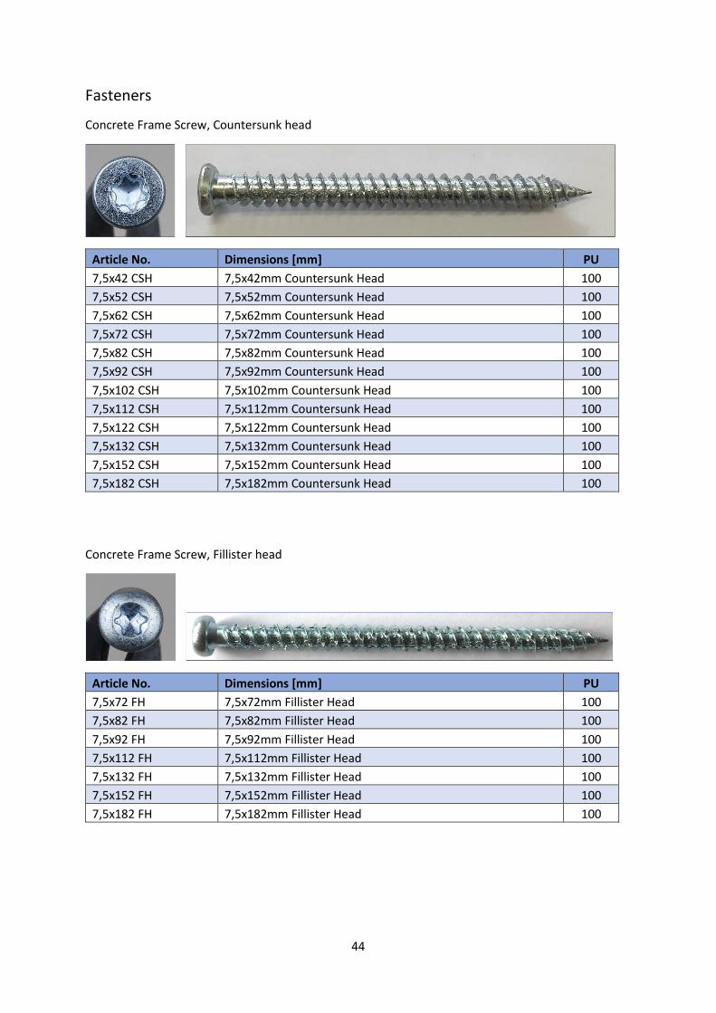
Fasteners
Concrete Frame Screw, Countersunk head
Article No. Dimensions [mm] PU
7,5x42 CSH 7,5x42mm Countersunk Head 100
7,5x52 CSH 7,5x52mm Countersunk Head 100
7,5x62 CSH 7,5x62mm Countersunk Head 100
7,5x72 CSH 7,5x72mm Countersunk Head 100
7,5x82 CSH 7,5x82mm Countersunk Head 100
7,5x92 CSH 7,5x92mm Countersunk Head 100
7,5x10² CSH 7,5x102mm Countersunk Head 100
7,5x112 CSH 7,5x112mm Countersunk Head 100
7,5x122 CSH 7,5x122mm Countersunk Head 100
7,5x132 CSH 7,5x132mm Countersunk Head 100
7,5x152 CSH 7,5x152mm Countersunk Head 100
7,5x182 CSH 7,5x182mm Countersunk Head 100
Concrete Frame Screw, Fillister head
Article No. Dimensions [mm] PU
7,5x72 FH 7,5x72mm Fillister Head 100
7,5x82 FH 7,5x82mm Fillister Head 100
7,5x92 FH 7,5x92mm Fillister Head 100
7,5x112 FH 7,5x112mm Fillister Head 100
7,5x132 FH 7,5x132mm Fillister Head 100
7,5x152 FH 7,5x152mm Fillister Head 100
7,5x182 FH 7,5x182mm Fillister Head 100
45
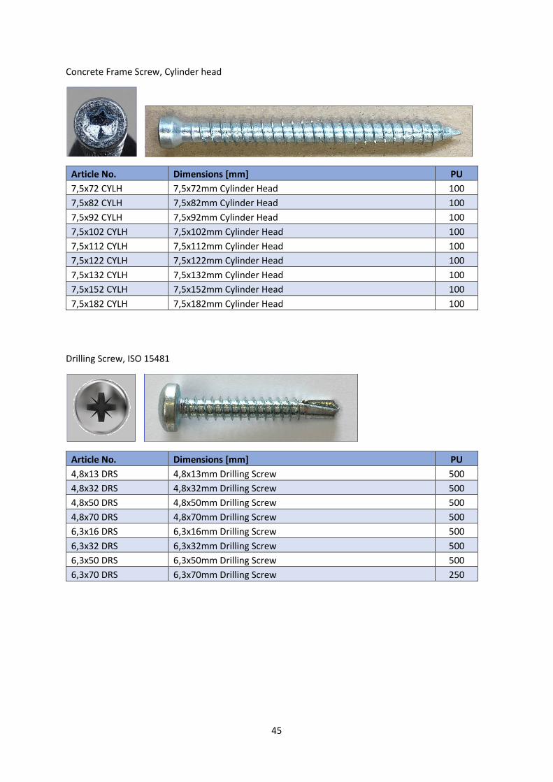
Concrete Frame Screw, Cylinder head
Article No. Dimensions [mm] PU
7,5x72 CYLH 7,5x72mm Cylinder Head 100
7,5x82 CYLH 7,5x82mm Cylinder Head 100
7,5x92 CYLH 7,5x92mm Cylinder Head 100
7,5x10² CYLH 7,5x102mm Cylinder Head 100
7,5x112 CYLH 7,5x112mm Cylinder Head 100
7,5x122 CYLH 7,5x122mm Cylinder Head 100
7,5x132 CYLH 7,5x132mm Cylinder Head 100
7,5x152 CYLH 7,5x152mm Cylinder Head 100
7,5x182 CYLH 7,5x182mm Cylinder Head 100
Drilling Screw, ISO 15481
Article No. Dimensions [mm] PU
4,8x13 DRS 4,8x13mm Drilling Screw 500
4,8x32 DRS 4,8x32mm Drilling Screw 500
4,8x50 DRS 4,8x50mm Drilling Screw 500
4,8x70 DRS 4,8x70mm Drilling Screw 500
6,3x16 DRS 6,3x16mm Drilling Screw 500
6,3x32 DRS 6,3x32mm Drilling Screw 500
6,3x50 DRS 6,3x50mm Drilling Screw 500
6,3x70 DRS 6,3x70mm Drilling Screw 250
46
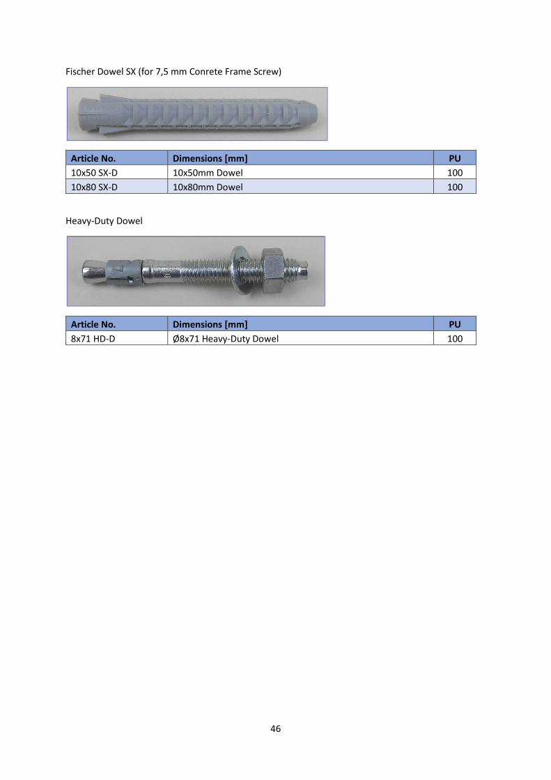
Fischer Dowel SX (for 7,5 mm Conrete Frame Screw)
Article No. Dimensions [mm] PU
10x50 SX-D 10x50mm Dowel 100
10x80 SX-D 10x80mm Dowel 100
Heavy-Duty Dowel
Article No. Dimensions [mm] PU
8x71 HD-D Ø8x71 Heavy-Duty Dowel 100
47
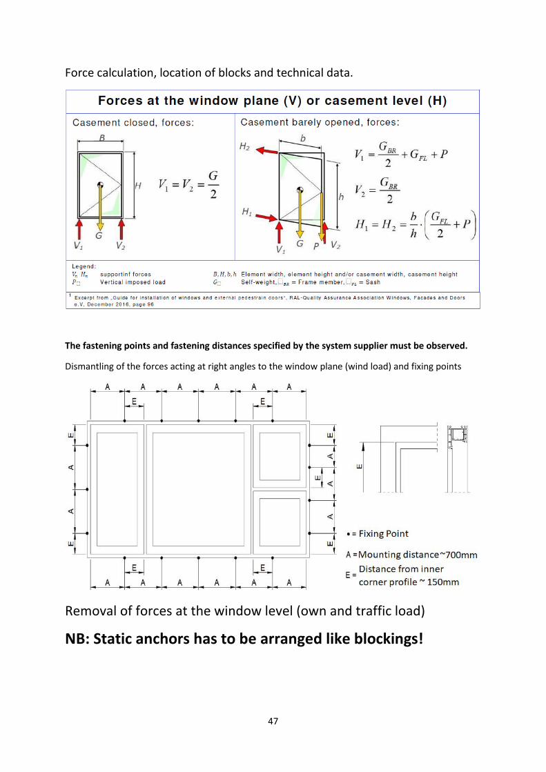
Force calculation, location of blocks and technical data.
The fastening points and fastening distances specified by the system supplier must be observed.
Dismantling of the forces acting at right angles to the window plane (wind load) and fixing points
Removal of forces at the window level (own and traffic load)
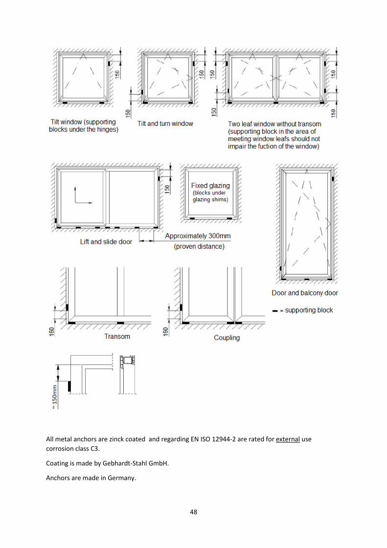
NB: Static anchors has to be arranged like blockings!
48
All metal anchors are zinck coated and regarding EN ISO 12944-2 are rated for external use
corrosion class C3.
Coating is made by Gebhardt-Stahl GmbH.
Anchors are made in Germany.