load flow analysissmart.tabrizu.ac.ir/files/content/smart/load-flow-analysis-6th-batch.pdf ·...
TRANSCRIPT

NATIONAL ELECTRIFICATION ADMINISTRATIONU. P. NATIONAL ENGINEERING CENTER
Certificate inPower System Modeling and Analysis
Competency Training and Certification Program in Electric Power Distribution System Engineering
U. P. NATIONAL ENGINEERING CENTER
Training Course in
Load Flow Analysis

2
Competency Training & Certification Program in Electric Power Distribution System Engineering
U. P. National Engineering CenterNational Electrification Administration
Training Course in Load Flow Analysis
Course Outline
1. The Load Flow Problem
2. Power System Models for Load Flow Analysis
3. Gauss-Seidel Load Flow
4. Newton-Raphson Load Flow
5. Backward/Forward Sweep Load Flow
6. Principles of Load Flow Control
7. Uses of Load Flow Studies

3
Competency Training & Certification Program in Electric Power Distribution System Engineering
U. P. National Engineering CenterNational Electrification Administration
Training Course in Load Flow Analysis
The Load Flow Problem
Basic Electrical Engineering Solution
Load Flow of Distribution System
Load Flow of Transmission and Subtransmission System
Load Flow of a Contemplated System
Load Flow of a Single Line

4
Competency Training & Certification Program in Electric Power Distribution System Engineering
U. P. National Engineering CenterNational Electrification Administration
Training Course in Load Flow Analysis
The Load Flow Problem
Basic Electrical Engineering Solution
How do you determine the voltage, current, power, and power factor at various points in a power system?
Sending End
Receiving End
VS = ?
Load2 MVA, 3Ph
85%PF
VR = 13.2 kVLL
Line1.1034 + j2.0856 ohms/phase
ISR = ?
VOLTAGE DROP = VS - VR
Solve for:
1) ISR = (SR/VR )*
2) VD = ISRZL
3) VS = VR + VD
4) SS = VSx(ISR)*

5
Competency Training & Certification Program in Electric Power Distribution System Engineering
U. P. National Engineering CenterNational Electrification Administration
Training Course in Load Flow Analysis
The Load Flow ProblemSending
EndReceiving
End
VS = ?
Load2 MVA, 3Ph
85%PF
VR = 13.2 kVLL
Line1.1034 + j2.0856 ohms/phase
ISR = ?
Solve for:
1) ISR = (SR/VR )*
2) VD = ISRZL
3) VS = VR + VD
4) SS = VSx(ISR)*
( )( )( )
11
R
SR
S
S ( 2,000,000 / 3 ) cos (0.85 )
666 ,666.67 31.79 VA
V (13,200 / 3 ) 0 7621.02 0 V
666,666.67 31.79I 87.48 31.79 A7621.02 0
VD 87.48 31.79 1.1034 j2.0856 178.15 j104.23 V
V 7621.02 j0 178
φ−
∗
= ∠
= ∠
= ∠ = ∠
∠⎛ ⎞= = ∠ −⎜ ⎟∠⎝ ⎠= ∠ − + = +
= + + ( )
S
.15 j104.23 7,799.87 0.77 V
V 7,799.87 0.77 /1000* 3 13.51 k V
+ = ∠
= ∠ =

6
Competency Training & Certification Program in Electric Power Distribution System Engineering
U. P. National Engineering CenterNational Electrification Administration
Training Course in Load Flow Analysis
The Load Flow Problem
Load Flow From the Real World
Sending End
Receiving End
VS = 13.2 kVLL VR = ?
Line1.1034 + j2.0856 ohms/phase
ISR = ?
Load2 MVA, 3Ph
85%PFHow do you solve for:
1) ISR = ?
2) VD = ?
3) VR = ?
4) SS = ?

7
Competency Training & Certification Program in Electric Power Distribution System Engineering
U. P. National Engineering CenterNational Electrification Administration
Training Course in Load Flow Analysis
The Load Flow Problem
Load Flow of Distribution System
Bus1Bus2
Bus3
Bus4V1 = 67 kVV2 = ?
V4 = ?
V3 = ?I23 , Loss23 = ?
I24 , Loss24 = ?
I12 , Loss12 = ?
P1 , Q1 = ?P2 , Q2 = ?
P3 , Q3 = ?
P4 , Q4 = ?
Utility Grid
Lumped Load A2 MVA 85%PF
Lumped Load B1 MVA 85%PFHow do you solve
for the Voltages, Currents, Power and Losses?

8
Competency Training & Certification Program in Electric Power Distribution System Engineering
U. P. National Engineering CenterNational Electrification Administration
Training Course in Load Flow Analysis
The Load Flow Problem
Load Flow of Transmission and Subtransmission System
Line 1Line 1
Line 3Line 3Line 2Line 2
11 22
33
G G
How do you solve for the Voltages, Currents and Power of a LOOP power system?

9
Competency Training & Certification Program in Electric Power Distribution System Engineering
U. P. National Engineering CenterNational Electrification Administration
Training Course in Load Flow Analysis
The Load Flow Problem
Load Flow of a Contemplated System
How about if there are contemplated changes in the System?
How will you determine in advance the effects of:• Growth or addition of new loads• Addition of generating plants• Upgrading of Substation• Expansion of distribution lines
before the proposed changes are implemented?
Answer: LOAD FLOW ANALYSIS

10
Competency Training & Certification Program in Electric Power Distribution System Engineering
U. P. National Engineering CenterNational Electrification Administration
Training Course in Load Flow Analysis
The Load Flow Problem
Load Flow Analysis simulates (i.e., mathematically determine) the performance of an electric power system under a given set of conditions.
Load Flow (also called Power Flow) is a snapshot picture of the power system at a given point.

11
Competency Training & Certification Program in Electric Power Distribution System Engineering
U. P. National Engineering CenterNational Electrification Administration
Training Course in Load Flow Analysis
The Load Flow Problem
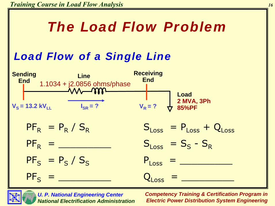
Load Flow of a Single Line
Sending End
Receiving End
VS = 13.2 kVLL VR = ?
Line1.1034 + j2.0856 ohms/phase
ISR = ?
Load2 MVA, 3Ph 85%PF
SR = VR x (ISR)*
Injected Power at Receiving End
VS = VR + Z x ISR
Voltage at Sending End
ISR = (SR / VR)*
Solving for the Current
VR = VS - Z x SR*/VR*
Voltage at Receiving End

12
Competency Training & Certification Program in Electric Power Distribution System Engineering
U. P. National Engineering CenterNational Electrification Administration
Training Course in Load Flow Analysis
The Load Flow Problem
Load Flow of a Single Line
Sending End
Receiving End
VS = 13.2 kVLL VR = ?
Line1.1034 + j2.0856 ohms/phase
ISR = ?
Load2 MVA, 3Ph 85%PF
Converting Quantities in Per Unit
VS(pu) = 13.2 /13.2 = 1/0Base Power = 1 MVA
Base Voltage = 13.2 kV
Base Impedance = [13.2]2/1
= 174.24 ohms
SR(pu) = 2/cos-1(0.85) / 1
Zpu = (1.1034 + j2.0856)/174.24
= 0.00633 + j0.01197

13
Competency Training & Certification Program in Electric Power Distribution System Engineering
U. P. National Engineering CenterNational Electrification Administration
Training Course in Load Flow Analysis
The Load Flow Problem
Load Flow of a Single LineSending
EndReceiving
End
VS = 13.2 kVLL VR = ?
Line1.1034 + j2.0856 ohms/phase
ISR = ?
Load2 MVA, 3Ph 85%PF
VR(k) = VS - Z x [SR]* / [VR
(k-1) ]*
Let VR(0) = 1/0
For k = 1VR
(1) = __________
∆V(1) = __________
For k = 2VR
(2) = __________
∆V(2) = __________

14
Competency Training & Certification Program in Electric Power Distribution System Engineering
U. P. National Engineering CenterNational Electrification Administration
Training Course in Load Flow Analysis
The Load Flow Problem
Load Flow of a Single Line
Sending End
Receiving End
VS = 13.2 kVLL VR = ?
Line1.1034 + j2.0856 ohms/phase
ISR = ?
Load2 MVA, 3Ph 85%PF
VR(k) = VS - Z x [SR]* / [VR
(k-1) ]*
For k = 3VR
(3) = __________
∆V(3) = __________
For k = 4VR
(4) = __________
∆V(4) = __________
VR(2) = __________

15
Competency Training & Certification Program in Electric Power Distribution System Engineering
U. P. National Engineering CenterNational Electrification Administration
Training Course in Load Flow Analysis
The Load Flow Problem
Load Flow of a Single Line
Sending End
Receiving End
VS = 13.2 kVLL VR = ?
Line1.1034 + j2.0856 ohms/phase
ISR = ?
Load2 MVA, 3Ph 85%PF
ISR = __________
SR = __________
SS = VS x [ISR]*
SS = __________
VS = __________
VR = __________
VD = VS – VR
VD = __________
16
Competency Training & Certification Program in Electric Power Distribution System Engineering
U. P. National Engineering CenterNational Electrification Administration
Training Course in Load Flow Analysis
The Load Flow Problem
Load Flow of a Single Line
Sending End
Receiving End
VS = 13.2 kVLL VR = ?
Line1.1034 + j2.0856 ohms/phase
ISR = ?
Load2 MVA, 3Ph 85%PF
SLoss = PLoss + QLoss
SLoss = SS - SR
PLoss = _________
QLoss = _________
PFR = PR / SR
PFR = _________
PFS = PS / SS
PFS = _________

17
Competency Training & Certification Program in Electric Power Distribution System Engineering
U. P. National Engineering CenterNational Electrification Administration
Training Course in Load Flow Analysis
Power System Models for Load flow Analysis
Bus Admittance Matrix, Ybus
Network Models
Generator Models
Bus Types for Load Flow Analysis

18
Competency Training & Certification Program in Electric Power Distribution System Engineering
U. P. National Engineering CenterNational Electrification Administration
Training Course in Load Flow Analysis
Power System Models for Load Flow Analysis
The power system components are interconnected through the buses. The buses must therefore be identified in the load flow model.
Generators and loads are connected from bus to neutral.Transmission lines and transformers are connected from one bus to another bus.

19
Competency Training & Certification Program in Electric Power Distribution System Engineering
U. P. National Engineering CenterNational Electrification Administration
Training Course in Load Flow Analysis
⎥⎥⎥⎥⎥⎥⎥⎥
⎦
⎤
⎢⎢⎢⎢⎢⎢⎢⎢
⎣
⎡
nn3n2n1n
n3333231
n2232221
n1131211
YYYY
YYYY
YYYY
YYYY
L
MMMM
L
L
L
[YBUS] =
The static components (transformers and lines) are represented by the bus admittance matrix, Ybus
The number of buses (excluding the neutral bus) determines the dimension of the bus admittance, Ybus.
Network Models
Power System Models for Load Flow Analysis

20
Competency Training & Certification Program in Electric Power Distribution System Engineering
U. P. National Engineering CenterNational Electrification Administration
Training Course in Load Flow Analysis
Power System Models for Load Flow Analysis
Network ModelsLine No. Bus Code Impedance Zpq (p.u.)
1 1 - 2 0.08 + j0.24 2 1 - 3 0.02 + j0.06 3 2 - 3 0.06 + j0.18
Line 1Line 1
Line 3Line 3Line 2Line 2
11 22
33
Set-up the Ybus

21
Competency Training & Certification Program in Electric Power Distribution System Engineering
U. P. National Engineering CenterNational Electrification Administration
Training Course in Load Flow Analysis
Power System Models for Load Flow Analysis
Network Models
Compute the branch admittances to set up Ybus:
y12 = ____1z12
= ______________10.08 + j0.24
= 1.25 - j3.75
y13 = ____1z13
= ______________10.02 + j0.06
= 5 - j15
y23 = ____1z23
= ______________10.06 + j0.18
= 1.667 - j5

22
Competency Training & Certification Program in Electric Power Distribution System Engineering
U. P. National Engineering CenterNational Electrification Administration
Training Course in Load Flow Analysis
Set-up the bus admittance matrix:
Power System Models for Load Flow Analysis
Y11 = y12 + y13
= (1.25 - j3.75) + (5 - j15)= 6.25 - j18.75 = 19.7642 ∠ -71.5651°
Y12 = -y12
= -1.25 + j3.75 = 3.9528 ∠ 108.4349°
Y13 = -y13= -5 + j15 = 15.8114 ∠ 108.4349°
Y21 = Y12 = -y12= -1.25 + j3.75 = 3.9528 ∠ 108.4349°

23
Competency Training & Certification Program in Electric Power Distribution System Engineering
U. P. National Engineering CenterNational Electrification Administration
Training Course in Load Flow Analysis
Power System Models for Load Flow Analysis
Y22 = y12 + y23
= (1.25 - j3.75) + (1.6667 - j5)= 2.9167 - j8.75 = 9.2233 ∠ -71.5649°
Y23 = -y23= -1.6667 + j5 = 5.2705 ∠ 108.4349°
Y31 = Y13 = -y13= -5 + j15 = 15.8114 ∠ 108.4349°
Y32 = Y23 = -y23
= -1.6667 + j5 = 5.2705 ∠ 108.4349°= (5 - j15) + (1.6667 - j5)Y33 = y13 + y23
= 6.6667 - j20 = 21.0819 ∠ -71.5650°

24
Competency Training & Certification Program in Electric Power Distribution System Engineering
U. P. National Engineering CenterNational Electrification Administration
Training Course in Load Flow Analysis
Power System Models for Load Flow Analysis
Voltage-controlled generating units to supply a scheduled active power (P) at a specified voltage (V). The generating units are equipped with voltage regulator to adjust the field excitation so that the units will operate at particular reactive power (Q) in order to maintain the voltage. Swing generating units to maintain the frequency at 60Hz in addition to maintaining the specified voltage. The generating unit is equipped with frequency-following controller (very fast speed governor) and is assigned as Swing generator
Generator Models

25
Competency Training & Certification Program in Electric Power Distribution System Engineering
U. P. National Engineering CenterNational Electrification Administration
Training Course in Load Flow Analysis
Power System Models for Load Flow Analysis
Bus Types for Load Flow
Generators and loads are connected from bus to neutral.
Four quantities must be specified to completely describe a bus. These are:
Bus voltage magnitude, VpBus voltage phase angle, δpBus injected active power, PpBus injected reactive power, Qp
26
Competency Training & Certification Program in Electric Power Distribution System Engineering
U. P. National Engineering CenterNational Electrification Administration
Training Course in Load Flow Analysis
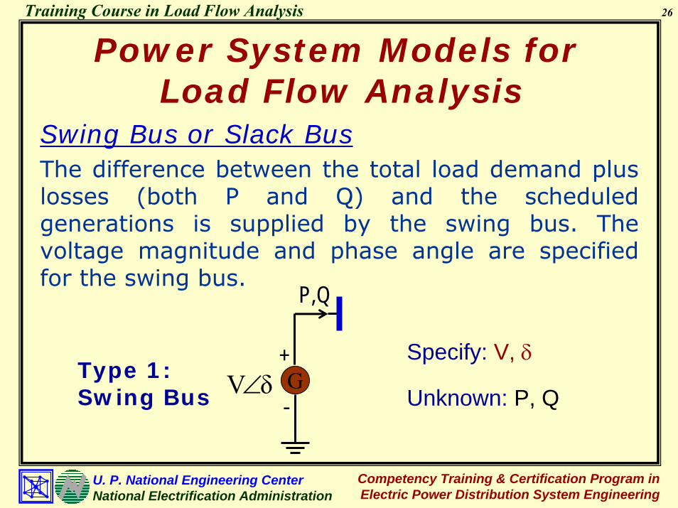
Swing Bus or Slack BusThe difference between the total load demand plus losses (both P and Q) and the scheduled generations is supplied by the swing bus. The voltage magnitude and phase angle are specified for the swing bus.
Type 1: Swing Bus
Specify: V, δ
Unknown: P, QG
P,QP,Q
δV∠++
--
Power System Models for Load Flow Analysis

27
Competency Training & Certification Program in Electric Power Distribution System Engineering
U. P. National Engineering CenterNational Electrification Administration
Training Course in Load Flow Analysis
Generator Bus (Voltage-Controlled) Bus or PV BusThe total real power Pp injected into the system through the bus is specified together with the magnitude of the voltage Vp at the bus. The bus voltage magnitude is maintained through reactive power injection.
G
P,QP,Q
δV∠++
--
Specify: P, VType 2: Generator Bus
Unknown: Q, δ
Power System Models for Load Flow Analysis

28
Competency Training & Certification Program in Electric Power Distribution System Engineering
U. P. National Engineering CenterNational Electrification Administration
Training Course in Load Flow Analysis
Power System Models for Load Flow Analysis
Load Bus or PQ Bus
The total injected power Pp and the reactive power Qp at Bus P are specified and are assumed constant, independent of the small variations in bus voltage.
P,QP,Q
++Type 3: Load Bus
Specify: P, Q
--δV∠
Unknown: V, δ
29
Competency Training & Certification Program in Electric Power Distribution System Engineering
U. P. National Engineering CenterNational Electrification Administration
Training Course in Load Flow Analysis
Power System Models for Load Flow Analysis
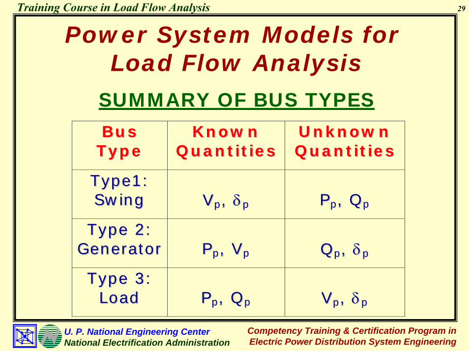
SUMMARY OF BUS TYPES
BB uu ss TT yy pp ee
KK nn oo ww nn QQ uu aa nn tt iitt iiee ss
UU nn kk nn oo ww nn QQ uu aa nn tt iitt iiee ss
TT yy pp ee 11 :: SS ww iinn gg
VV pp ,, δδ pp
PP pp ,, QQ pp
TT yy pp ee 22 :: GG ee nn ee rraa ttoo rr
PP pp ,, VV pp
QQ pp ,, δδ pp
TT yy pp ee 33 :: LL oo aa dd
PP pp ,, QQ pp
VV pp ,, δδ pp

30
Competency Training & Certification Program in Electric Power Distribution System Engineering
U. P. National Engineering CenterNational Electrification Administration
Training Course in Load Flow Analysis
Line 1Line 1
Line 3Line 3Line 2Line 2
11 22
33
G G
Power System Models for Load Flow Analysis
Voltage Generation Load Bus No. V (p.u.) δ P Q P Q
Remarks
1 1.0 0.0 * * 0 0 Swing Bus 2 1.0 * 0.20 * 0 0 Gen Bus 3 * * 0 0 0.60 0.25 Load Bus
Bus Types

31
Competency Training & Certification Program in Electric Power Distribution System Engineering
U. P. National Engineering CenterNational Electrification Administration
Training Course in Load Flow Analysis
Gauss-Seidel Load Flow
Linear Formulation of Load Flow Equations
Gauss-Seidel Load Flow Solution
Numerical Example

32
Competency Training & Certification Program in Electric Power Distribution System Engineering
U. P. National Engineering CenterNational Electrification Administration
Training Course in Load Flow Analysis
Gauss-Seidel Load Flow
The real and reactive power into any bus P is:
Linear Formulation of Load Flow Equations
Pp + jQp = Vp Ip*
or(1)Pp - jQp = Vp
* Ip
where Pp = real power injected into bus P
Qp = reactive power injected into bus P
Vp = phasor voltage of bus P
Ip = current injected into bus P

33
Competency Training & Certification Program in Electric Power Distribution System Engineering
U. P. National Engineering CenterNational Electrification Administration
Training Course in Load Flow Analysis
Equation (1) may be rewritten as:
Ip = Pp - jQp_________
Vp*
Gauss-Seidel Load Flow
(2)
From the Bus Admittance Matrix equation, the current injected into the bus are:
Ip = Yp1V1 + Yp2V2 + … + YppVp + … + YpnVn (3)
I1 = Y11V1 + Y12V2 + Y13V3
I2 = Y21V1 + Y22V2 + Y23V3
I3 = Y31V1 + Y32V2 + Y33V3

34
Competency Training & Certification Program in Electric Power Distribution System Engineering
U. P. National Engineering CenterNational Electrification Administration
Training Course in Load Flow Analysis
Gauss-Seidel Load Flow
Substituting (3) into (2)
_________Vp
*
Pp - jQp= Yp1V1 + Yp2V2 + … + YppVp + … + YpnVn
_________V1
*
P1 – jQ1= Y11V1 + Y12V2 + Y13V3
(4)
_________V2
*
P2 – jQ2= Y21V1 + Y22V2 + Y23V3
_________V3
*
P3 – jQ3= Y31V1 + Y32V2 + Y33V3

35
Competency Training & Certification Program in Electric Power Distribution System Engineering
U. P. National Engineering CenterNational Electrification Administration
Training Course in Load Flow Analysis
Gauss-Seidel Load FlowSolving for Vp in (4)
_______Y11V1 = P1 – jQ1
V1*
- (___ + Y12V2 + Y13V3)
⎥⎦
⎤⎢⎣
⎡−−
−= 313212*
1
11
11
1 VYVYV
jQPY1V
_______Y22V2 = P2 – jQ2
V2*
- (Y12V2 + ___ + Y13V3)
⎥⎦
⎤⎢⎣
⎡−−
−= 313121*
2
22
22
2 VYVYV
jQPY1V

36
Competency Training & Certification Program in Electric Power Distribution System Engineering
U. P. National Engineering CenterNational Electrification Administration
Training Course in Load Flow Analysis
Gauss-Seidel Load Flow
⎥⎦
⎤⎢⎣
⎡−−
−= 232131*
3
33
33
3 VYVYV
jQPY1V
_______Y33V3 = P3 – jQ3
V3*
- (Y13V1 + Y23V2 + ___)
Vp =1___
Ypp
_______ Vp
*
Pp - jQp Σ-n
q=1q≠p
YpqVq (5)

37
Competency Training & Certification Program in Electric Power Distribution System Engineering
U. P. National Engineering CenterNational Electrification Administration
Training Course in Load Flow Analysis
Gauss-Seidel Load Flow
Gauss-Seidel Load Flow Solution
Generalizing the Gauss-Seidel Load Flow, the estimate for the voltage Vp at bus p at the kth
iteration is:
Vpk+1 =
1___Ypp
_______ (Vp
k)*
Pp - jQp Σ-n
q=1q≠p
YpqVqα
where, α = k if p < qα = k + 1 if p > q
(6)

38
Competency Training & Certification Program in Electric Power Distribution System Engineering
U. P. National Engineering CenterNational Electrification Administration
Training Course in Load Flow Analysis
Gauss-Seidel Load FlowGauss-Seidel Voltage Equations of the form shown in (6) are written for all buses except for the swing bus. The solution proceeds iteratively from an estimate of all bus voltages
For a Load Bus (Type 3) whose real power and reactive power are specified, the G-S voltage equation is used directly to compute the next estimate of the bus voltage.
For a Generator Bus (Type 2) where the voltage magnitude is specified, an estimate of Qp must be determined first. This estimate is then compared with the reactive power limits of the generator. If it falls within the limits, the specified voltage is maintained and the computed Qp is inputted, in the Gauss-Seidel equation. Otherwise, the reactive power is set to an appropriate limit (Qmin or Qmax) and the bus is treated as a load bus in the current iteration.
39
Competency Training & Certification Program in Electric Power Distribution System Engineering
U. P. National Engineering CenterNational Electrification Administration
Training Course in Load Flow Analysis
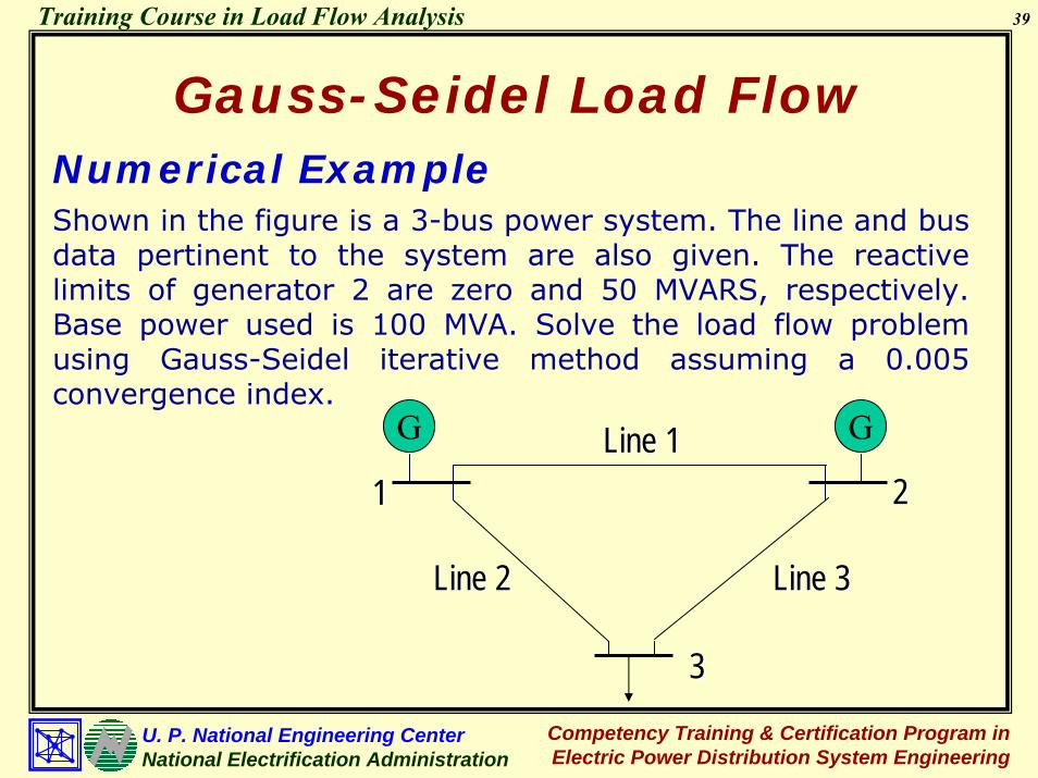
Gauss-Seidel Load FlowNumerical ExampleShown in the figure is a 3-bus power system. The line and bus data pertinent to the system are also given. The reactive limits of generator 2 are zero and 50 MVARS, respectively. Base power used is 100 MVA. Solve the load flow problem using Gauss-Seidel iterative method assuming a 0.005 convergence index.
Line 1Line 1
Line 3Line 3Line 2Line 2
11 22
33
G G

40
Competency Training & Certification Program in Electric Power Distribution System Engineering
U. P. National Engineering CenterNational Electrification Administration
Training Course in Load Flow Analysis
Gauss-Seidel Load Flow
Branch Data
Line No. Bus Code Impedance Zpq (p.u.)
1 1 - 2 0.08 + j0.24 2 1 - 3 0.02 + j0.06 3 2 - 3 0.06 + j0.18
Bus DataVoltage Generation Load Bus
No. V (p.u.) δ P Q P Q Remarks
1 1.0 0.0 * * 0 0 Swing Bus 2 1.0 * 0.20 * 0 0 Gen Bus 3 * * 0 0 0.60 0.25 Load Bus
41
Competency Training & Certification Program in Electric Power Distribution System Engineering
U. P. National Engineering CenterNational Electrification Administration
Training Course in Load Flow Analysis
Gauss-Seidel Load Flow
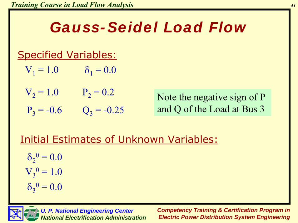
Specified Variables:V1 = 1.0 δ1 = 0.0
V2 = 1.0 P2 = 0.2 Note the negative sign of P and Q of the Load at Bus 3P3 = -0.6 Q3 = -0.25
Initial Estimates of Unknown Variables:
δ20 = 0.0
V30 = 1.0
δ30 = 0.0

42
Competency Training & Certification Program in Electric Power Distribution System Engineering
U. P. National Engineering CenterNational Electrification Administration
Training Course in Load Flow Analysis
Gauss-Seidel Load Flow
The Bus Admittance Matrix elements are:Y11 = 6.25 - j18.75 = 19.7642 ∠ -71.5651°Y12 = -1.25 + j3.75 = 3.9528 ∠ 108.4349°Y13 = -5 + j15 = 15.8114 ∠ 108.4349°Y21 = -1.25 + j3.75 = 3.9528 ∠ 108.4349°Y22 = 2.9167 - j8.75 = 9.2233 ∠ -71.5649°Y23 = -1.6667 + j5 = 5.2705 ∠ 108.4349°Y31 = -5 + j15 = 15.8114 ∠ 108.4349°Y32 = -1.6667 + j5 = 5.2705 ∠ 108.4349°Y33 = 6.6667 - j20 = 21.0819 ∠ -71.5650°

43
Competency Training & Certification Program in Electric Power Distribution System Engineering
U. P. National Engineering CenterNational Electrification Administration
Training Course in Load Flow Analysis
Gauss-Seidel Load FlowGauss-Seidel EquationsBus 1: Swing Bus
( ) 01V 1k1 ∠=+
for all iterations
Bus 2: Generator BusQ2 must first be determined from:
P2 - jQ2(k+1) = (V2
(k))* [Y21V1(k+1) + Y22V2
(k) + Y23V3(k)]
then substitute it to:
( )( )
( )( )( ) ( )
⎥⎥⎦
⎤
⎢⎢⎣
⎡−−
−= +
++ k
3231k
121*k2
1k22
22
1k2 VYVY
V
jQPY
1V
44
Competency Training & Certification Program in Electric Power Distribution System Engineering
U. P. National Engineering CenterNational Electrification Administration
Training Course in Load Flow Analysis
Gauss-Seidel Load Flow
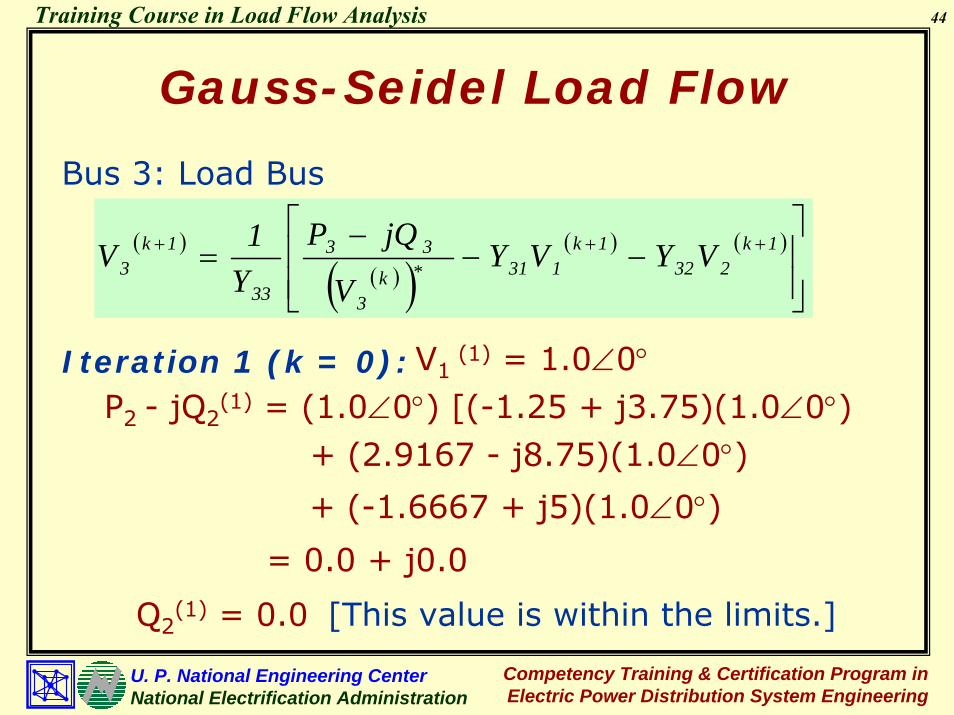
Bus 3: Load Bus
( )( )( )
( ) ( )
⎥⎥⎦
⎤
⎢⎢⎣
⎡−−
−= +++ 1k
2321k
131*k3
33
33
1k3 VYVY
V
jQPY1V
Iteration 1 (k = 0): V1 (1) = 1.0∠0°
P2 - jQ2(1) = (1.0∠0°) [(-1.25 + j3.75)(1.0∠0°)
+ (2.9167 - j8.75)(1.0∠0°)
+ (-1.6667 + j5)(1.0∠0°)
= 0.0 + j0.0
Q2(1) = 0.0 [This value is within the limits.]

45
Competency Training & Certification Program in Electric Power Distribution System Engineering
U. P. National Engineering CenterNational Electrification Administration
Training Course in Load Flow Analysis
Gauss-Seidel Load Flow
( )( )
( )( )( ) ( )
⎥⎥⎦
⎤
⎢⎢⎣
⎡−−
−= +
++ k
3231k
121*k2
1k22
22
1k2 VYVY
V
jQPY1V
( )1k22 jQP +−
V2(1) =
1___________________9.2233∠-71.5650
0.2 - j0.0
1.0∠0°___________
- (-1.25 +j3.75) (1.0∠0°)
- (-1.6667 + j5) (1.0∠0°)
21Y
23Y
( )1k1V +
( )k3V
( )( )*k2V22Y
= 1.0071∠1.1705°

46
Competency Training & Certification Program in Electric Power Distribution System Engineering
U. P. National Engineering CenterNational Electrification Administration
Training Course in Load Flow Analysis
Gauss-Seidel Load Flow
V31 =
1_____________________21.0819∠-71.5650
-0.6 + j0.25
1.0∠0°____________
- (-5 +j15) (1.0∠0°)
- (5.2705∠108.4349°)(1.0071∠1.1705°)
33Y31Y
32Y
33 jQP −
( )*k3V
( )1k1V +
( )1k2V +
( )( )( )
( ) ( )
⎥⎥⎦
⎤
⎢⎢⎣
⎡−−
−= +++ 1k
2321k
131*k3
33
33
1k3 VYVY
V
jQPY1V
= 0.9816 ∠-1.0570°

47
Competency Training & Certification Program in Electric Power Distribution System Engineering
U. P. National Engineering CenterNational Electrification Administration
Training Course in Load Flow Analysis
Gauss-Seidel Load Flow
∆V2 = V2(1) - V2
(0)
= 1.0071∠1.1705° - 1.0∠0°
∆V2 = 0.0217
∆V3 = V3(1) - V3
(0)
= 0.9816∠-1.0570° - 1.0∠0°
∆V3 = 0.0259

48
Competency Training & Certification Program in Electric Power Distribution System Engineering
U. P. National Engineering CenterNational Electrification Administration
Training Course in Load Flow Analysis
Gauss-Seidel Load Flow
Iteration 2 (k = 1): V1(2) = 1.0∠0°
Let, V2(1) = 1.0∠1.1705°
P2 - jQ2(2) = (1.0∠-1.1705°)[(-1.25 + j3.75)(1.0∠0°)
+ (9.2233∠-71.5649°)(1.0∠1.1705°)
+ (5.2705∠108.4349° )(0.9816∠-1.0570°)
= 0.2995 - j0.0073
Q2 (2) = 0.0073 [This value is within the limits.]

49
Competency Training & Certification Program in Electric Power Distribution System Engineering
U. P. National Engineering CenterNational Electrification Administration
Training Course in Load Flow Analysis
Gauss-Seidel Load Flow
( )( )
( )( )( ) ( )
⎥⎥⎦
⎤
⎢⎢⎣
⎡−−
−= +
++ k
3231k
121*k2
1k22
22
1k2 VYVY
V
jQPY1V
0.2 - j0.0073
1.0 ∠ -1.1705°______________V2
(2) =1___________________
9.2233 ∠ -71.5650
- (-1.25 +j3.75) (1.0 ∠ 0°)
- (5.2705 ∠ 108.4349° ) (0.9816 ∠ -1.0570°)
= 0.9966 ∠ 0.5819°

50
Competency Training & Certification Program in Electric Power Distribution System Engineering
U. P. National Engineering CenterNational Electrification Administration
Training Course in Load Flow Analysis
Gauss-Seidel Load Flow
( )( )( )
( ) ( )
⎥⎥⎦
⎤
⎢⎢⎣
⎡−−
−= +++ 1k
2321k
131*k3
33
33
1k3 VYVY
V
jQPY1V
-0.6 + j0.25
0.9816 ∠ 1.0570°___________________V3
(2) =1_____________________
21.0819 ∠ -71.5650
- (-5 +j15) (1.0 ∠ 0°)
- (5.2705 ∠ 108.4349°) (0.9966 ∠ 0.5819° )
= 0.9783 ∠ -1.2166°

51
Competency Training & Certification Program in Electric Power Distribution System Engineering
U. P. National Engineering CenterNational Electrification Administration
Training Course in Load Flow Analysis
Gauss-Seidel Load Flow
∆V2 = V2(2) - V2
(1)
= 0.9966 ∠ 0.5819° - 1.0071 ∠ 1.1705°
∆V2 = 0.0125
∆V3 = V3(2) - V3
(1)
= 0.9783 ∠ -1.2166° - 0.9816 ∠ -1.0570°
∆V3 = 0.004

52
Competency Training & Certification Program in Electric Power Distribution System Engineering
U. P. National Engineering CenterNational Electrification Administration
Training Course in Load Flow Analysis
Gauss-Seidel Load Flow
Iteration 3 (k = 2): V1(2) = 1.0∠0°
Let, V22 = 1.0 ∠ 0.5819°
P2 - jQ22 = (1.0 ∠-0.5819°) [(-1.25 + j3.75)(1.0 ∠ 0°)
+ (9.2233 ∠ -71.5649° ) (1.0 ∠ 0.5819°)
+ (5.2705 ∠ 108.4349° ) (0.9783 ∠ -1.2166° )
= 0.2287 - j0.0472
Q22 = 0.0472 [This value is within the limits.]

53
Competency Training & Certification Program in Electric Power Distribution System Engineering
U. P. National Engineering CenterNational Electrification Administration
Training Course in Load Flow Analysis
Gauss-Seidel Load Flow
( )( )
( )( )( ) ( )
⎥⎥⎦
⎤
⎢⎢⎣
⎡−−
−= +
++ k
3231k
121*k2
1k22
22
1k2 VYVY
V
jQPY1V
V23 =
1___________________9.2233 ∠ -71.5650
0.2 - j0.0472
1.0 ∠ -0.5819°______________
- (-1.25 +j3.75) (1.0 ∠ 0°)
- (5.2705 ∠ 108.4349° ) (0.9783 ∠ -1.2166° )
= 0.9990 ∠ 0.4129°

54
Competency Training & Certification Program in Electric Power Distribution System Engineering
U. P. National Engineering CenterNational Electrification Administration
Training Course in Load Flow Analysis
Gauss-Seidel Load Flow
( )( )( )
( ) ( )
⎥⎥⎦
⎤
⎢⎢⎣
⎡−−
−= +++ 1k
2321k
131*k3
33
33
1k3 VYVY
V
jQPY1V
-0.6 + j0.25
0.9783 ∠ 1.2166°
___________________V33 =
1_____________________21.0819 ∠-71.5650
- (-5 +j15)(1.0∠0°)
- (5.2705∠108.4349°)(0.9990∠0.4129°)
= 0.9788∠-1.2560°

55
Competency Training & Certification Program in Electric Power Distribution System Engineering
U. P. National Engineering CenterNational Electrification Administration
Training Course in Load Flow Analysis
Gauss-Seidel Load Flow
∆V2 = V2(3) - V2
(2)
= 0.9990∠0.4129° - 1.0∠0.5819°
∆V2 = 0.003 < 0.005
∆V3 = V3(3) - V3
(2)
= 0.9788∠-1.2560° - 0.9783∠-1.2166°
∆V3 = 0.0008 < 0.005
The solution has converged.

56
Competency Training & Certification Program in Electric Power Distribution System Engineering
U. P. National Engineering CenterNational Electrification Administration
Training Course in Load Flow Analysis
Newton-Raphson Load Flow
Non-Linear Formulation of Load Flow Equations
Newton-Raphson Load Flow Solution
Numerical Example

57
Competency Training & Certification Program in Electric Power Distribution System Engineering
U. P. National Engineering CenterNational Electrification Administration
Training Course in Load Flow Analysis
Newton-Raphson Load Flow
Non-Linear Formulation of Load Flow Equations
The complex power injected into Bus p is*
p p p pP jQ E I− =and the current equation may be written as
(1)
n
p pq qq 1
I Y E=
= ∑Substituting (2) into (1)
(2)
(3)q
n
1qpq
*ppp EYEjQP ∑
=
•=−

58
Competency Training & Certification Program in Electric Power Distribution System Engineering
U. P. National Engineering CenterNational Electrification Administration
Training Course in Load Flow Analysis
Newton-Raphson Load FlowLet
p p pE V δ= ∠ q q qE V δ= ∠
p q p q p qY Y θ= ∠Substituting into equation (3),
n
p p p q pq pq q pq 1
P jQ V V Y ( )θ δ δ=
− = ∠ + −∑
n
(4)
Separating the real and imaginary components
p p q pq pq q pq 1
P V V Y co s( )θ δ δ=
= + −∑n
p p q pq pq q pq 1
Q V V Y sin( )θ δ δ=
= − + −∑
(5)
(6)
59
Competency Training & Certification Program in Electric Power Distribution System Engineering
U. P. National Engineering CenterNational Electrification Administration
Training Course in Load Flow Analysis
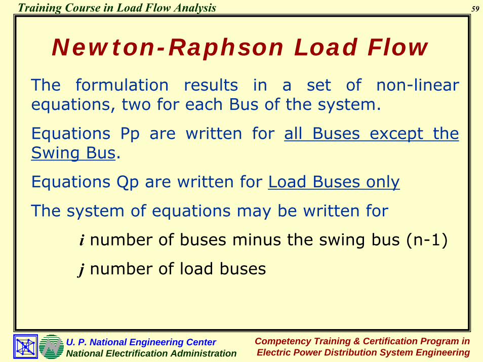
Newton-Raphson Load FlowThe formulation results in a set of non-linear equations, two for each Bus of the system.
Equations Pp are written for all Buses except the Swing Bus.
Equations Qp are written for Load Buses only
The system of equations may be written for
i number of buses minus the swing bus (n-1)
j number of load buses

60
Competency Training & Certification Program in Electric Power Distribution System Engineering
U. P. National Engineering CenterNational Electrification Administration
Training Course in Load Flow Analysis
Newton-Raphson Load FlowThe system of equations may be written as
1 1 1 2 i 1 2 jP P ( , ,..., ,v ,v ....,v )δ δ δ=
2 2 1 2 i 1 2 jP P ( , ,..., ,v ,v ....,v )δ δ δ=
i i 1 2 i 1 2 jP P ( , ,..., ,v ,v ....,v )δ δ δ=
1 1 1 2 i 1 2 jQ Q ( , ,..., ,v ,v ....,v )δ δ δ=
2 2 1 2 i 1 2 jQ Q ( , ,..., ,v ,v ....,v )δ δ δ=
jj 1 2 i 1 2 jQ Q ( , ,..., ,v ,v ....,v )δ δ δ=
M M
M M
(7)

61
Competency Training & Certification Program in Electric Power Distribution System Engineering
U. P. National Engineering CenterNational Electrification Administration
Training Course in Load Flow Analysis
Newton-Raphson Load FlowEquation (7) may be linearized using a First-Order Taylor-Series Expansion
spec calc 1 1 1 1 1 11 1 1 2 i 1 2 j
1 2 i 1 2 j
spec calc 2 2 2 2 2 22 2 1 2 i 1 2 j
1 2 i 1 2 j
spec calc i ii i 1 2
1 2
P P P P P PP P ... V V ... V
V V V
P P P P P PP P ... V V ... V
V V V
P PP P ...
∆δ ∆δ ∆δ ∆ ∆ ∆δ δ δ
∆δ ∆δ ∆δ ∆ ∆ ∆δ δ δ
∆δ ∆δδ δ
∂ ∂ ∂ ∂ ∂ ∂= + + + + + + + +
∂ ∂ ∂ ∂ ∂ ∂
∂ ∂ ∂ ∂ ∂ ∂= + + + + + + + +
∂ ∂ ∂ ∂ ∂ ∂
∂ ∂= + + + +
∂ ∂i i i i
i 1 2 j2 1 2 j
spec calc 1 1 1 1 1 11 1 1 2 i 1 2 j
1 2 i 1 2 j
spec calc 2 2 2 2 2 22 2 1 2 i 1 2
1 2 i 1 2
P P P PV V ... V
V V V
Q Q Q Q Q QQ Q ... V V ... V
V V V
Q Q Q Q Q QQ Q ... V V ...
V V
∆δ ∆ ∆ ∆δ
∆δ ∆δ ∆δ ∆ ∆ ∆δ δ δ
∆δ ∆δ ∆δ ∆ ∆δ δ δ
∂ ∂ ∂ ∂+ + + +
∂ ∂ ∂ ∂
∂ ∂ ∂ ∂ ∂ ∂= + + + + + + + +
∂ ∂ ∂ ∂ ∂ ∂
∂ ∂ ∂ ∂ ∂ ∂= + + + + + + + +
∂ ∂ ∂ ∂ ∂ ∂ jj
j j j j j jspec calcj j 1 2 i 1 2 j
1 2 i 1 2 j
VV
Q Q Q Q Q QQ Q ... V V ... V
V V V
∆
∆δ ∆δ ∆δ ∆ ∆ ∆δ δ δ
∂ ∂ ∂ ∂ ∂ ∂= + + + + + + + +
∂ ∂ ∂ ∂ ∂ ∂
M M M M M M M M M
M M M M M M M M M

62
Competency Training & Certification Program in Electric Power Distribution System Engineering
U. P. National Engineering CenterNational Electrification Administration
Training Course in Load Flow Analysis1 1 1 1 1 1s p e c c a lc
1 11 2 i 1 2 j
2 2 2 2s p e c c a lc2 2
1 2 i 1
s p e c c a lci i
s p e c c a lc1 1
s p e c c a lc2 2
s p e c c a lcj j
P P P P P PP P
V V V
P P P PP P
V
P P
Q Q
Q Q
Q Q
δ δ δ
δ δ δ
∂ ∂ ∂ ∂ ∂ ∂⎡ ⎤−
∂ ∂ ∂ ∂ ∂ ∂⎢ ⎥⎢ ⎥
∂ ∂ ∂ ∂⎢ ⎥−⎢ ⎥ ∂ ∂ ∂ ∂⎢ ⎥
⎢ ⎥⎢ ⎥⎢ ⎥⎢ ⎥⎢ ⎥⎢ ⎥−⎢ ⎥
=⎢ ⎥⎢ ⎥
−⎢ ⎥⎢ ⎥⎢ ⎥⎢ ⎥−⎢ ⎥⎢ ⎥⎢ ⎥⎢ ⎥⎢ ⎥⎢ ⎥⎢ ⎥−⎢ ⎥⎣ ⎦
L L
L
M
M
2 2
2 j
i i i i i i
1 2 2 1 2 j
1 1 1 1 1 1
1 2 i 1 2 j
2 2 2 2 2 2
1 2 i 1 2 j
j j j j j j
1 2 i 1 2 j
P PV V
P P P P P PV V V
Q Q Q Q Q QV V V
Q Q Q Q Q QV V V
Q Q Q Q Q QV V V
δ δ δ
δ δ δ
δ δ δ
δ δ δ
⎡⎢⎢⎢ ∂ ∂⎢⎢ ∂ ∂⎢⎢⎢⎢⎢∂ ∂ ∂ ∂ ∂ ∂⎢
⎢ ∂ ∂ ∂ ∂ ∂ ∂⎢⎢ ∂ ∂ ∂ ∂ ∂ ∂⎢⎢ ∂ ∂ ∂ ∂ ∂ ∂⎢⎢ ∂ ∂ ∂ ∂ ∂ ∂⎢∂ ∂ ∂ ∂ ∂ ∂⎢
∂ ∂ ∂ ∂ ∂ ∂
∂ ∂ ∂ ∂ ∂ ∂⎣
L
M M M M M M
L L
L L
L L
M M M M M M M
L L
1
2
i
1
2
j
V
V
V
∆ δ
∆ δ
∆ δ
∆
∆
∆
⎤⎡ ⎤⎥⎢ ⎥⎥⎢ ⎥⎥⎢ ⎥⎥⎢ ⎥⎥⎢ ⎥⎥⎢ ⎥⎥⎢ ⎥⎥⎢ ⎥⎥⎢ ⎥⎥⎢ ⎥⎥⎢ ⎥⎥⎢ ⎥⎥⎢ ⎥⎥⎢ ⎥⎥⎢ ⎥⎥⎢ ⎥⎥⎢ ⎥⎥⎢ ⎥⎥⎢ ⎥⎥⎢ ⎥⎢ ⎥⎢ ⎥⎢ ⎥⎢ ⎥⎢ ⎥⎢ ⎥⎢ ⎥⎢ ⎥⎢ ⎥⎢ ⎥⎢ ⎥ ⎣ ⎦⎢ ⎥⎦
M
M

63
Competency Training & Certification Program in Electric Power Distribution System Engineering
U. P. National Engineering CenterNational Electrification Administration
Training Course in Load Flow Analysis
Newton-Raphson Load Flowor simply
⎥⎦
⎤⎢⎣
⎡∆∆
⎥⎥⎥
⎦
⎤
⎢⎢⎢
⎣
⎡
∂∂
∂∂
∂∂
∂∂
=⎥⎦
⎤⎢⎣
⎡∆∆
VVQQVPP
QP δ
δ
δ
⎥⎥⎦
⎤
⎢⎢⎣
⎡∆∆
⎥⎥⎥
⎦
⎤
⎢⎢⎢
⎣
⎡
∂∂
∂∂
∂∂
∂∂
=⎥⎦
⎤⎢⎣
⎡∆∆
VV
VQVQVPVP
QP δ
δ
δ

64
Competency Training & Certification Program in Electric Power Distribution System Engineering
U. P. National Engineering CenterNational Electrification Administration
Training Course in Load Flow Analysis
Newton-Raphson Load FlowNewton-Raphson Load Flow Solution
1 2
3 4
J JP
VJ JQ V
∆δ∆
∆∆
⎡ ⎤⎡ ⎤⎡ ⎤⎢ ⎥⎢ ⎥⎢ ⎥⎢ ⎥= ⎢ ⎥⎢ ⎥⎢ ⎥⎢ ⎥⎢ ⎥⎢ ⎥⎣ ⎦ ⎣ ⎦ ⎣ ⎦
np
p q p q p q q pq 1 ,q pp
1p
p q p q p q q pq
PV V Y sin ( )
JP
V V Y sin ( )
θ δ δδ
θ δ δδ
= ≠
∂⎧= + −⎪ ∂⎪
⎨ ∂⎪ = − + −⎪ ∂⎩
∑

65
Competency Training & Certification Program in Electric Power Distribution System Engineering
U. P. National Engineering CenterNational Electrification Administration
Training Course in Load Flow Analysis
Newton-Raphson Load Flow
p 2p p p p p p p
p2
pq p q p q p q q p
q
np
p q p q p q q pq 1 ,q pp
3p
p q p q p q q pq
PV P V Y c o s
VJ
PV V V Y c o s ( )
V
QV V Y c o s ( )
JQ
V V Y c o s ( )
θ
θ δ δ
θ δ δδ
θ δ δδ
= ≠
∂⎧= +⎪ ∂⎪
⎨ ∂⎪ = + −⎪ ∂⎩∂⎧
= + −⎪ ∂⎪⎨ ∂⎪ = − + −⎪ ∂⎩
∑

66
Competency Training & Certification Program in Electric Power Distribution System Engineering
U. P. National Engineering CenterNational Electrification Administration
Training Course in Load Flow Analysis
Newton-Raphson Load Flow
p 2p p p p p p q
p4
pq p q p q p q q p
q
QV Q V Y sin
VJ
QV V V Y sin ( )
V
θ
θ δ δ
∂⎧= −⎪ ∂⎪
⎨ ∂⎪ = − + −⎪ ∂⎩
The solution of the load flow equations proceeds iteratively from the set of initial estimates. These estimates are updated after evaluating the Jacobianmatrix.

67
Competency Training & Certification Program in Electric Power Distribution System Engineering
U. P. National Engineering CenterNational Electrification Administration
Training Course in Load Flow Analysis
Newton-Raphson Load FlowAt the kth iteration,
( k 1 ) ( k ) ( k )p p p
( k 1 ) ( k ) ( k )p p pV V V
δ δ ∆δ
∆
+
+
= +
= +
The process is terminated once convergence is achieved whrein
( k ) ( k )p qMAX P and MAX Q∆ ε ∆ ε≤ ≤

68
Competency Training & Certification Program in Electric Power Distribution System Engineering
U. P. National Engineering CenterNational Electrification Administration
Training Course in Load Flow Analysis
Numerical ExampleShown in the figure is a 3-bus power system. The line and bus data pertinent to the system are also given. The reactive limits of generator 2 are zero and 50 MVARS, respectively. Base power used is 100 MVA. Solve the load flow problem using Gauss-Seidel iterative method assuming a 0.005 convergence index.
Line 1Line 1
Line 3Line 3Line 2Line 2
11 22
33
G G
Newton-Raphson Load Flow

69
Competency Training & Certification Program in Electric Power Distribution System Engineering
U. P. National Engineering CenterNational Electrification Administration
Training Course in Load Flow Analysis
Newton-Raphson Load Flow
Branch Data
Line No. Bus Code Impedance Zpq (p.u.)
1 1 - 2 0.08 + j0.24 2 1 - 3 0.02 + j0.06 3 2 - 3 0.06 + j0.18
Bus DataVoltage Generation Load Bus
No. V (p.u.) δ P Q P Q Remarks
1 1.0 0.0 * * 0 0 Swing Bus 2 1.0 * 0.20 * 0 0 Gen Bus 3 * * 0 0 0.60 0.25 Load Bus

70
Competency Training & Certification Program in Electric Power Distribution System Engineering
U. P. National Engineering CenterNational Electrification Administration
Training Course in Load Flow Analysis
Newton-Raphson Load FlowThe elements of the Bus Admittance Matrix are:
11
12
13
21
22
23
31
Y 6.25 j18.75 19.7642 71.5651Y 1,25 j3.75 3.9528 108.4349Y 5 j15 15.8114 108.4349Y 1.25 j .375 3.9528 108.4349Y 2.9167 j8.75 9.2233 71.5649Y 1.6667 j5 5.2705 108.4349Y 5 j15 15.811
= − = ∠ −= − + = ∠= − + = ∠
= − + = ∠= − = ∠ −= − + = ∠
= − + =
32
33
4 108.4349Y 1.6667 j5 5.2705 108.4349Y 6.6667 j 20 21.0819 71.5650
∠
= − + = ∠
= − = ∠ −

71
Competency Training & Certification Program in Electric Power Distribution System Engineering
U. P. National Engineering CenterNational Electrification Administration
Training Course in Load Flow Analysis
Newton-Raphson Load FlowBus 1: Swing Bus (Not included)
Bus 2: Generator Bus (Compute for P2)
Bus 32: Generator Bus (Compute for P2 and Q2)
2 2 22 3 2
2 3 3
3 3 33 3 3
2 3 3
3 3 3 33 3
2 3 3 3
P P PP VV
P P PP VV
Q Q Q VQ VV V
∆ ∆δδ δ
∆ ∆δδ δ
∆∆δ δ
⎡ ⎤⎡ ⎤∂ ∂ ∂⎡ ⎤ ⎢ ⎥⎢ ⎥∂ ∂ ∂⎢ ⎥ ⎢ ⎥⎢ ⎥⎢ ⎥ ⎢ ⎥ ⎢ ⎥
∂ ∂ ∂⎢ ⎥ ⎢ ⎥⎢ ⎥=⎢ ⎥ ⎢ ⎥ ⎢ ⎥∂ ∂ ∂⎢ ⎥ ⎢ ⎥⎢ ⎥⎢ ⎥ ⎢ ⎥ ⎢ ⎥∂ ∂ ∂⎢ ⎥ ⎢ ⎥⎢ ⎥⎣ ⎦ ∂ ∂ ∂⎢ ⎥⎢ ⎥⎣ ⎦ ⎣ ⎦

72
Competency Training & Certification Program in Electric Power Distribution System Engineering
U. P. National Engineering CenterNational Electrification Administration
Training Course in Load Flow Analysis
Newton-Raphson Load Flow
Specified Variables:V1 = 1.0 δ1 = 0.0
V2 = 1.0 P2 = 0.2
P3 = -0.6 Q3 = -0.25
Initial Estimates of Unknown Variables:
δ20 = 0.0
V30 = 1.0
δ30 = 0.0

73
Competency Training & Certification Program in Electric Power Distribution System Engineering
U. P. National Engineering CenterNational Electrification Administration
Training Course in Load Flow Analysis
Newton-Raphson Load FlowCompute Initial Power Estimates
02 2 1 21 21 1 2
2 2 22 22 2 3 23 23 3 2
P V V Y cos( ) V V Y cos V V Y cos( ) ( 1.0 )( 1.0 )( 3.9528 )cos( 108.4349 0.0 0.0 ) ( 1.0 )( 1.0 )( 9.2233 )cos( 71.5649 ) ( 1.0 )( 1.0 )( 5.2705 )cos( 108.4349 ) 0.0
θ δ δθ θ δ δ
= + −+ + + −
= + ++ −+
=

74
Competency Training & Certification Program in Electric Power Distribution System Engineering
U. P. National Engineering CenterNational Electrification Administration
Training Course in Load Flow Analysis
Newton-Raphson Load Flow
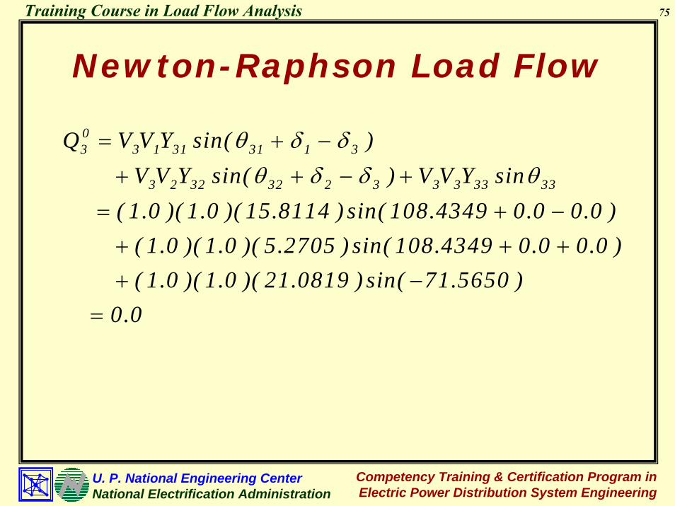
03 3 1 31 31 1 3
3 2 32 22 2 3 3 3 33 33
P V V Y cos( ) V V Y cos( ) V V Y cos ( 1.0 )(1.0 )(15.8114 )cos(108.4349 0.0 0.0 ) ( 1.0 )(1.0 )( 5.2705 )cos(108.4349 0.0 0.0 ) ( 1.0 )(1.0 )( 21.0819 )cos( 71.5650 )
θ δ δθ δ δ θ
= + −
+ + − +
= + −+ + ++ −
0.0=
75
Competency Training & Certification Program in Electric Power Distribution System Engineering
U. P. National Engineering CenterNational Electrification Administration
Training Course in Load Flow Analysis
Newton-Raphson Load Flow
03 3 1 31 31 1 3
3 2 32 32 2 3 3 3 33 33
Q V V Y sin( ) V V Y sin( ) V V Y sin ( 1.0 )( 1.0 )( 15.8114 ) sin( 108.4349 0.0 0.0 ) ( 1.0 )( 1.0 )( 5.2705 ) sin( 108.4349 0.0 0.0 ) ( 1.0 )( 1.0 )( 21.0819 ) sin( 71.5650 )
θ δ δθ δ δ θ
= + −+ + − +
= + −+ + ++ −
0.0=

76
Competency Training & Certification Program in Electric Power Distribution System Engineering
U. P. National Engineering CenterNational Electrification Administration
Training Course in Load Flow Analysis
Newton-Raphson Load FlowCompute Power Mismatch
02P 0 .2 0 .0 0 .2∆ = − =
03P 0 .6 0 .0 0 .6∆ = − − = −03Q 0 .2 5 0 .0 0 .2 5∆ = − − = −
Evaluate elements of Jacobian Matrix
P PV
JQ QV
V
δ δ
δ
∂ ∂⎡ ⎤⎢ ⎥∂ ∂⎢ ⎥=⎢ ⎥∂ ∂⎢ ⎥⎢ ⎥∂ ∂⎣ ⎦

77
Competency Training & Certification Program in Electric Power Distribution System Engineering
U. P. National Engineering CenterNational Electrification Administration
Training Course in Load Flow Analysis
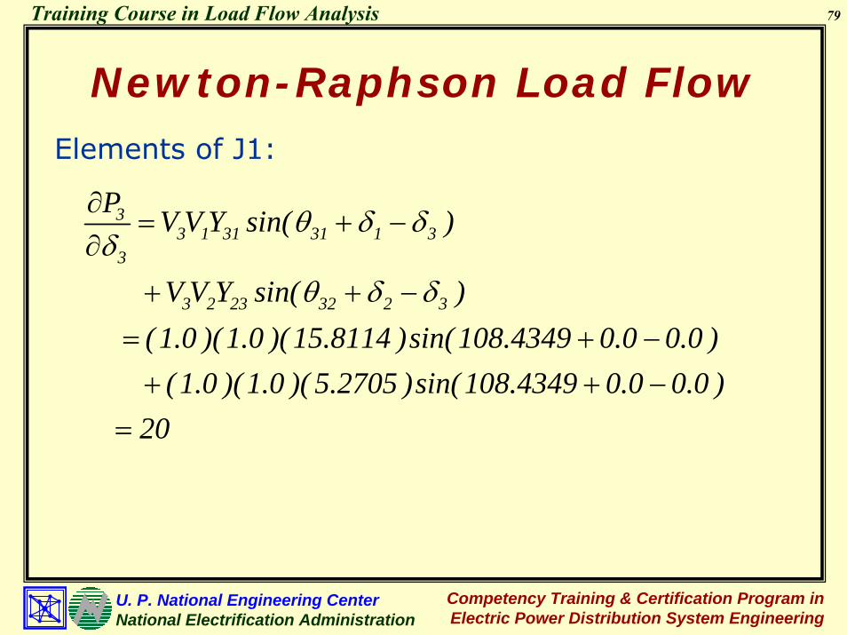
Newton-Raphson Load FlowElements of J1:
22 1 21 21 1 2
2
2 3 23 23 3 2
P V V Y sin( )
V V Y sin( ) ( 1.0 )(1.0 )( 3.9528 )sin(108.4349 0.0 0.0 ) ( 1.0 )(1.0 )( 5.2705 )sin(108.4349 0.0 0.0 ) 8.75
θ δ δδ
θ δ δ
∂= + −
∂+ + −
= + −+ + −
=

78
Competency Training & Certification Program in Electric Power Distribution System Engineering
U. P. National Engineering CenterNational Electrification Administration
Training Course in Load Flow Analysis
Newton-Raphson Load FlowNewton-Raphson Load FlowElements of J1:
22 3 23 23 3 2
3
PV V Y sin( )
( 1.0 )(1.0 )( 5.2705 )sin(108.4349 0.0 0.0 ) 5
θ δ δδ∂
= − + −∂
= − + −= −
33 2 32 32 2 3
2
PV V Y sin( )
( 1.0 )(1.0 )( 5.2705 )sin(108.4349 0.0 0.0 ) 5
θ δ δδ∂
= − + −∂
= − + −= −
79
Competency Training & Certification Program in Electric Power Distribution System Engineering
U. P. National Engineering CenterNational Electrification Administration
Training Course in Load Flow Analysis
Newton-Raphson Load FlowElements of J1:
33 1 31 31 1 3
3
3 2 23 32 2 3
P V V Y sin( )
V V Y sin( ) ( 1.0 )(1.0 )(15.8114 )sin(108.4349 0.0 0.0 ) ( 1.0 )(1.0 )( 5.2705 )sin(108.4349 0.0 0.0 ) 20
θ δ δδ
θ δ δ
∂= + −
∂+ + −
= + −+ + −
=

80
Competency Training & Certification Program in Electric Power Distribution System Engineering
U. P. National Engineering CenterNational Electrification Administration
Training Course in Load Flow Analysis
Newton-Raphson Load FlowElements of J2:
( )232323323
23 cos δδθ ++=∂∂ YVVVPV
( )( )( ) ( )6667.1
0.00.04349.108cos2705.50.10.1−=
−+=
233 3 3 33 33
32
PV P V Y cosV
0.0 ( 1.0 ) ( 8.2233 )cos( 71.5649 ) 2.9167
θ∂= +
∂
= + −=

81
Competency Training & Certification Program in Electric Power Distribution System Engineering
U. P. National Engineering CenterNational Electrification Administration
Training Course in Load Flow Analysis
Newton-Raphson Load FlowElements of J3:
33 2 32 32 2 3
2
QV V Y cos( )
( 1.0 )(1.0 )( 5.2705 )cos(108.4349 0.0 0.0 ) 1.6667
θ δ δδ∂
= − + −∂
= − + −=
33 1 31 31 1 3
3
3 2 32 32 2 3
Q V V Y cos( )
V Y Y cos( ) ( 1.0 )( 1.0 )( 15.8114 )cos( 108.4349 0.0 0.0 ) ( 1.0 )( 1.0 )( 5.2705 )cos( 108.4349 0.0 0.0 ) 6.6667
θ δ δδ
θ δ δ
∂= + −
∂+ + −
= + −+ + −
= −

82
Competency Training & Certification Program in Electric Power Distribution System Engineering
U. P. National Engineering CenterNational Electrification Administration
Training Course in Load Flow Analysis
Newton-Raphson Load FlowElements of J4:
233 3 3 33 33
32
PV Q V Y sin
0.0 (1.0 ) ( 21.0819 )sin( 71.5649 ) 20
θδ∂
= −∂
= − −=
In Matrix Form,
8.75 5 1.66675 20 2.9167
1.6667 6.6667 20
− −⎡ ⎤⎢ ⎥−⎢ ⎥⎢ ⎥−⎣ ⎦

83
Competency Training & Certification Program in Electric Power Distribution System Engineering
U. P. National Engineering CenterNational Electrification Administration
Training Course in Load Flow Analysis
Newton-Raphson Load FlowSolving for Gradients,
2
3
3 3
0.2 8.75 5 1.66670.6 5 20 2.91670.25 1.6667 6.6667 20 V /V
∆δ∆δ
∆
− −⎡ ⎤ ⎡ ⎤⎡ ⎤⎢ ⎥ ⎢ ⎥⎢ ⎥− = −⎢ ⎥ ⎢ ⎥⎢ ⎥⎢ ⎥ ⎢ ⎥⎢ ⎥− −⎣ ⎦ ⎣ ⎦⎣ ⎦
02 0.003984rad. 0.2283deg∆δ = =
03
3
V 0.02145V∆
= − 03V 0.02145∆ = −
deg4822.1.rad02587.003 −=−=δ∆

84
Competency Training & Certification Program in Electric Power Distribution System Engineering
U. P. National Engineering CenterNational Electrification Administration
Training Course in Load Flow Analysis
Newton-Raphson Load FlowUpdate Initial Estimates
1 0 02 2 2δ δ ∆δ= +121 0 03 3 3
131 0 0
3 3 31
3
0.0 0.2283 0.2283
0.0 1.4822 1.4822
V V V
V 1.0 0.02145 0.97855
δ
δ δ ∆δ
δ
∆
= + =
= +
= − = −
= +
= − =
Specified Variables1
1111
2
V 1.0
0.0
V 1.0
δ
=
=
=

85
Competency Training & Certification Program in Electric Power Distribution System Engineering
U. P. National Engineering CenterNational Electrification Administration
Training Course in Load Flow Analysis
Newton-Raphson Load FlowUpdate Estimates of Injected Power
12 2 1 21 31 1 3
2 2 22 22
2 3 23 23 3 2
P VVY cos( ) VV Y cos( ) VV Y cos( ) = (1.0)(1.0)(3.9528)cos(108.4349 0.0 0.2283) (1.0)(1.0)(9.2233)cos( 71.5649) (1.0)(0.97855)(5.2705)cos(10
θ δ δθθ δ δ
= + −++ + −
+ −+ −+ 8.4349 1.4822 0.2283)
0.1975− −
=
4822.1+

86
Competency Training & Certification Program in Electric Power Distribution System Engineering
U. P. National Engineering CenterNational Electrification Administration
Training Course in Load Flow Analysis
Newton-Raphson Load FlowUpdate Estimates of Injected Power
13 3 1 31 31 1 3
3 2 32 32 2 3
3 3 33 33
P V V Y cos( ) V V Y cos( ) V V Y cos( ) = (0.97855 )(1.0 )(15.8114 )cos(108.4349 0.0 1.4822 ) (0.97855 )(1.0 )( 5.2705 )cos(108.4349 0.2283 1.4822 ) (0.97
θ δ δθ δ δθ
= + −
+ + −
++ +
+ + ++ 855 )(0.97855 )( 21.0819 )cos( 71.5650 )
0.66633−
= −

87
Competency Training & Certification Program in Electric Power Distribution System Engineering
U. P. National Engineering CenterNational Electrification Administration
Training Course in Load Flow Analysis
Newton-Raphson Load FlowUpdate Estimates of Injected Power
[
][
13 3 1 31 31 1 3
3 2 32 32 2 3
3 3 33 33
Q V V Y sin( ) V V Y sin( ) V V Y sin( )
= - (0.97855)(1.0 )(15.8114 )sin(108.4349 0.0 1.4822) (0.97855)(1.0 )(5.2705)sin(108.4349 0.2283 1.4822) (0.
θ δ δθ δ δθ
= − + −
+ + −
+
+ +
+ + +
+ ]97855)(0.97855)( 21.0819 )sin( 71.5650 ) 0.2375
−
= −

88
Competency Training & Certification Program in Electric Power Distribution System Engineering
U. P. National Engineering CenterNational Electrification Administration
Training Course in Load Flow Analysis
Newton-Raphson Load FlowCompute Power Mismatch
2 2 ,sp 2 ,ca lc
3 3 ,sp 3 ,ca lc
3 3 ,sp 3 ,ca lc
P P P
0 .2 0 .1 9 7 5 0 .0 0 2 5
P P P
0 .6 0 .6 6 3 3 0 .0 6 3 3
Q Q Q
.0 .2 5 0 .2 3 7 5 0 .0 1 2 5
∆
∆
∆
= −
= −
=
= −
= − +
=
= −
= − +
= Proceed to Iteration 2
89
Competency Training & Certification Program in Electric Power Distribution System Engineering
U. P. National Engineering CenterNational Electrification Administration
Training Course in Load Flow Analysis
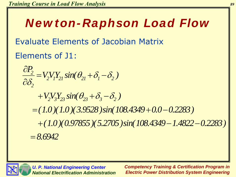
Newton-Raphson Load FlowEvaluate Elements of Jacobian Matrix
Elements of J1:
22 1 21 21 1 2
2
2 3 23 23 3 2
P VVY sin( )
VVY sin( ) (1.0)(1.0)(3.9528)sin(108.4349 0.0 0.2283) (1.0)(0.97855)(5.2705)sin(108.4349 1.4822 0.2283) 8.6942
θ δ δδ
θ δ δ
∂= + −
∂+ + −
= + −+ − −
=

90
Competency Training & Certification Program in Electric Power Distribution System Engineering
U. P. National Engineering CenterNational Electrification Administration
Training Course in Load Flow Analysis
Newton-Raphson Load FlowNewton-Raphson Load FlowElements of J1:
22 3 23 23 3 2
3
P VVY sin( )
(1.0)(0.97855)(5.2705)sin(108.4349 1.4822 0.2283) 4.9393
θ δ δδ∂
=− + −∂
=− − −=−
33 2 32 32 2 3
2
P VV Y sin( )
(0.97855)(1.0)(5.2705)sin(108.4349 0.2283 1.4822) 4.8419
θ δ δδ∂
=− + −∂
=− + +=−

91
Competency Training & Certification Program in Electric Power Distribution System Engineering
U. P. National Engineering CenterNational Electrification Administration
Training Course in Load Flow Analysis
Newton-Raphson Load FlowElements of J1:
33 1 31 31 1 3
3
3 2 23 32 2 3
P V VY sin( )
V V Y sin( ) (0.97855)(1.0 )(15.8114 )sin(108.4349 0.0 1.4822) (0.97855)(1.0 )(5.2705)sin(108.4349 0.2283 1.4822) 19.3887
θ δ δδ
θ δ δ
∂= + −
∂+ + −
= + ++ + +
=

92
Competency Training & Certification Program in Electric Power Distribution System Engineering
U. P. National Engineering CenterNational Electrification Administration
Training Course in Load Flow Analysis
Newton-Raphson Load FlowElements of J2:
( )232323323
23 cos δδθ ++=∂∂ YVVVPV
( )( )( ) ( )4842.1
2283.04822.14349.108cos2705.5097855.00.1−=
−+=
233 3 3 33 33
32
PV P V Y cosV
0.6633 (0.97855 ) ( 21.0819 )cos( 71.5650 ) 5.7205
θ∂= +
∂
= − + −=

93
Competency Training & Certification Program in Electric Power Distribution System Engineering
U. P. National Engineering CenterNational Electrification Administration
Training Course in Load Flow Analysis
Newton-Raphson Load FlowElements of J3:
33 2 32 32 2 3
2
Q VV Y cos( )
(0.97855)(1.0)(5.2705)cos(108.4349 0.2283 1.4822) 1.7762
θ δ δδ∂
=− + −∂
=− + +=3
3 1 31 31 1 33
3 2 32 32 2 3
Q V V Y cos( )
V Y Y cos( ) (0.97855 )(1.0 )(15.8114 )cos(108.4349 0.0 1.4822 ) (0.97855 )(1.0 )( 5.2705 )cos(108.4349 0.2283 1.4822 ) 7.0470
θ δ δδ
θ δ δ
∂= + −
∂
+ + −= + ++ + +
= −

94
Competency Training & Certification Program in Electric Power Distribution System Engineering
U. P. National Engineering CenterNational Electrification Administration
Training Course in Load Flow Analysis
Newton-Raphson Load FlowElements of J4:
233 3 3 33 33
32
PV Q V Y sin
0.2375 (0.97855 ) ( 21.0819 )sin( 71.565 ) 18.9137
θδ∂
= −∂
= − − −=
In Matrix Form,
8.6942 4.9393 1.48424.8419 19.3887 5.7205
1.7762 7.0470 18.9137
− −⎡ ⎤⎢ ⎥−⎢ ⎥⎢ ⎥−⎣ ⎦

95
Competency Training & Certification Program in Electric Power Distribution System Engineering
U. P. National Engineering CenterNational Electrification Administration
Training Course in Load Flow Analysis
Newton-Raphson Load FlowSolving for Gradients,
2
3
3 3
0.0025 8.6942 4.9393 1.48420.0633 4.8419 19.3887 5.72050.0125 1.7762 7.0470 18.9137 V / V
∆δ∆δ
∆
− −⎡ ⎤ ⎡ ⎤ ⎡ ⎤⎢ ⎥ ⎢ ⎥ ⎢ ⎥= −⎢ ⎥ ⎢ ⎥ ⎢ ⎥⎢ ⎥ ⎢ ⎥ ⎢ ⎥− −⎣ ⎦ ⎣ ⎦ ⎣ ⎦
0012 1458.0rad/180 x rad0025.0 == πδ∆
0013 2150.0rad/180 x rad0038.0 == πδ∆
0005.0VV
3
03 =
∆ ( )( ) 0005.097855.00005.0V 13 ==∆

96
Competency Training & Certification Program in Electric Power Distribution System Engineering
U. P. National Engineering CenterNational Electrification Administration
Training Course in Load Flow Analysis
Newton-Raphson Load FlowUpdate Previous Estimates
11111
2
V 1.0
0.0
V 1.0
δ
=
=
=
Specified Variables
2 1 12 2 2
0
2 1 13 3 3
0
2 1 13 3 3
0.2283 0.1458 0.3741
1.4822 0.2150 1.2672V V V 0.97855 0.0005 0.9791
δ δ ∆δ
δ δ ∆δ
∆
= +
= + =
= +
= − + = −
= +
= + =

97
Competency Training & Certification Program in Electric Power Distribution System Engineering
U. P. National Engineering CenterNational Electrification Administration
Training Course in Load Flow Analysis
Newton-Raphson Load FlowUpdate Previous Estimates of Injected Power
22 2 1 21 21 1 2
2 2 22 22
2 3 23 23 3 2
P V V Y cos( ) V V Y cos( ) V V Y cos( ) = (1.0 )(1.0 )( 3.9528 )cos(108.4349 0.0 0.3741) (1.0 )(1.0 )( 9.2233 )cos( 71.5649 ) (1.0 )(0.9791)( 5.2705 )cos(108
θ δ δθθ δ δ
= + −++ + −
+ −+ −+ .4349 1.2672 0.3741)
0.2018− −
=

98
Competency Training & Certification Program in Electric Power Distribution System Engineering
U. P. National Engineering CenterNational Electrification Administration
Training Course in Load Flow Analysis
Newton-Raphson Load FlowUpdate Previous Estimates of Injected Power
23 3 1 31 31 1 3
3 2 32 22 2 3 3 3 33 33
P V V Y cos( ) V V Y cos( ) V V Y cos (0.9791)(1.0 )(15.8114 )cos(108.4349 0.0 1.2672 ) ( 0.9791)(1.0 )( 5.2705 )cos(108.4349 0.3741 1.2672 ) ( 0.9791)(0.9791)(
θ δ δθ δ δ θ
= + −+ + − +
= + −+ + ++ 21.0819 )cos( 71.5650 )
0.5995−
= −

99
Competency Training & Certification Program in Electric Power Distribution System Engineering
U. P. National Engineering CenterNational Electrification Administration
Training Course in Load Flow Analysis
Newton-Raphson Load FlowUpdate Previous Estimates of Injected Power
[]
[
23 3 1 31 31 1 3
3 2 32 32 2 3 3 3 33 33
Q V V Y sin( )
V V Y sin( ) V V Y sin
(0.9791)(1.0 )(15.8114)sin(108.4349 0.0 1.2672) (0.9791)(1.0 )(5.2705)sin(108.4349 0.37411 1.2672) (0.9791)(0.979
θ δ δ
θ δ δ θ
= − + −
+ + − +
= − + −
+ + +
+ ]1)(21.0819)sin( 71.5650) 0.2487
−
= −

100
Competency Training & Certification Program in Electric Power Distribution System Engineering
U. P. National Engineering CenterNational Electrification Administration
Training Course in Load Flow Analysis
Newton-Raphson Load FlowCompute Power Mismatch
The solution has converged
2 2 ,s p 2 ,c a lc
3 3 ,s p 3 ,c a lc
3 3 ,s p 3 ,c a lc
P P P
0 .2 0 .2 0 1 8 0 .0 0 1 8
P P P
0 .6 0 .5 9 9 5 0 .0 0 0 5
Q Q Q
.0 .2 5 0 .2 4 8 7 0 .0 0 1 3
∆
∆
∆
= −
= −
=
= −
= − +
=
= −
= − +
=
101
Competency Training & Certification Program in Electric Power Distribution System Engineering
U. P. National Engineering CenterNational Electrification Administration
Training Course in Load Flow Analysis
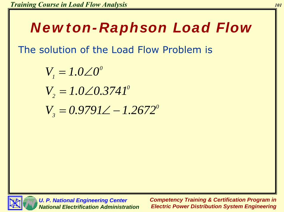
Newton-Raphson Load FlowThe solution of the Load Flow Problem is
03
02
01
2672.19791.0V3741.00.1V
00.1V
−∠=
∠=
∠=

102
Competency Training & Certification Program in Electric Power Distribution System Engineering
U. P. National Engineering CenterNational Electrification Administration
Training Course in Load Flow Analysis
The bus voltages are:
Information from a Load Flow Study
V1 = 1.0∠0°V2 = 0.9990∠0.4129°V3 = 0.9788∠-1.2560°
The power injected into the buses are:
P1 - jQ1 = (1.0∠0) [(19.7642∠-71.5651°)(1.0∠0°)P1 - jQ1 = V1
* [Y11V1 + Y12V2 + Y13V3 ]
+ (3.9528∠108.4349°)(0.9990∠0.4129°)
+ (15.8114∠108.4349°) (0.9788∠-1.25560°)= 0.4033 - j0.2272

103
Competency Training & Certification Program in Electric Power Distribution System Engineering
U. P. National Engineering CenterNational Electrification Administration
Training Course in Load Flow Analysis
P2 - jQ2 = V2* [Y21V1 + Y22V2 + Y23V3 ]
Information from a Load Flow Study
P2 - jQ2 = (0.999∠-0.4129°)[(3.9528∠108.4349°)(1.0∠0°)+ (9.2233∠-71.5649°)(0.9990∠0.4129°) + (5.2705∠108.4349°)(0.9788∠-1.25560°)
= 0.2025 - j0.04286
P3 - jQ3 = V3* [Y31V1 + Y32V2 + Y33V3 ]
P3 - jQ3 = (0.9788∠1.256°) [(15.8114∠108.4349°)(1.0∠0°)+ (5.2705∠108.4349°)(0.9990∠0.4129°) + (21.0819 ∠ -71.5650°)(0.9788∠-1.25560° )
= -0.600 + j0.2498

104
Competency Training & Certification Program in Electric Power Distribution System Engineering
U. P. National Engineering CenterNational Electrification Administration
Training Course in Load Flow Analysis
Information from a Load Flow Study
The branch currents are:
)VV(yII qppqlinepq −== )VV(yI I pqpqlineqp −=−=
I12 = y12 [V1 - V2] I21 = y12 [V2 – V1]
I13 = y13 [V1 – V3] I31 = y13 [V3 – V1]
I23 = y23 [V2 – V3] I32 = y23 [V3 – V2]

105
Competency Training & Certification Program in Electric Power Distribution System Engineering
U. P. National Engineering CenterNational Electrification Administration
Training Course in Load Flow Analysis
p qypo yqo
ypq VqIpq IlineVp
ppoqppqpolinepqVy )VV(yI II +
Iqp
The line current Ipq, measured at bus p is given by
Line Currents
Information from a Load Flow Study
−=+=
qqopqpqqolineqpVy )VV(yI I I +−=+−=
Similarly, the line current Iqp, measured at bus q is

106
Competency Training & Certification Program in Electric Power Distribution System Engineering
U. P. National Engineering CenterNational Electrification Administration
Training Course in Load Flow Analysis
Information from a Load Flow Study
The branch power flows are:
P12 – jQ12 = V1* I12 P21 – jQ21 = V2
* I21
P13 – jQ13 = V1* I13 P31 – jQ31 = V3
* I31
P23 – jQ23 = V2* I23 P32 – jQ32 = V3
* I32

107
Competency Training & Certification Program in Electric Power Distribution System Engineering
U. P. National Engineering CenterNational Electrification Administration
Training Course in Load Flow Analysis
Information from a Load Flow Study
Power FLOWS
The power flow (Spq) from bus p to q is
pqppqpqpq IVQj PS *=−=
The power flow (Sqp) from bus q to p is
qpqqpqpqp IVQj PS *=−=

108
Competency Training & Certification Program in Electric Power Distribution System Engineering
U. P. National Engineering CenterNational Electrification Administration
Training Course in Load Flow Analysis
Information from a Load Flow Study
The line losses are:
P12(Loss) – jQ12(Loss) = (P12 – jQ12) + (P21 – jQ21 )
P13(Loss) – jQ13(Loss) = (P13 – jQ13) + (P31 – jQ31 )
P23(Loss) – jQ23(Loss) = (P23 – jQ23) + (P32 – jQ32 )

109
Competency Training & Certification Program in Electric Power Distribution System Engineering
U. P. National Engineering CenterNational Electrification Administration
Training Course in Load Flow Analysis
Information from a Load Flow Study
Line Losses
The power loss in line pq is the algebraic sum of the power flows Spq and Sqp
qppqlosslosslossSSQj PS +=+=
( ) *pqqp
*pqq
*pqp
IVV
IVIV
+=
−=

110
Competency Training & Certification Program in Electric Power Distribution System Engineering
U. P. National Engineering CenterNational Electrification Administration
Training Course in Load Flow Analysis
Information from a Load Flow Study
BASIC INFORMATION
Voltage ProfileInjected Power (Pp and Qp)Line Currents (Ipq and Ipq)Power Flows (Ppq and Qpq)Line Losses (I2R and I2X)

111
Competency Training & Certification Program in Electric Power Distribution System Engineering
U. P. National Engineering CenterNational Electrification Administration
Training Course in Load Flow Analysis
Information from a Load Flow Study
OTHER INFORMATION
Overvoltage and Undervoltage BusesCritical and Overloaded Transformers and LinesTotal System Losses

112
Competency Training & Certification Program in Electric Power Distribution System Engineering
U. P. National Engineering CenterNational Electrification Administration
Training Course in Load Flow Analysis
Backward/Forward Sweep Load Flow
Load Flow for Radial Distribution System
Procedure: Iterative Solution
Initialization
Solving for Injected Currents through the nodes
Backward Sweep
Forward Sweep
Solving for Injected Power
Solving for Voltage Mismatch

113
Competency Training & Certification Program in Electric Power Distribution System Engineering
U. P. National Engineering CenterNational Electrification Administration
Training Course in Load Flow Analysis
Backward/Forward Sweep Load Flow
Bus1Bus2
Bus3
Bus4V1 = 67 kVV2 = ?
V4 = ?
V3 = ?
I23 , Loss23 = ?
I24 , Loss24 = ?
I12 , Loss12 = ?
P1 , Q1 = ?P2 , Q2 = ?
P3 , Q3 = ?
P4 , Q4 = ?
0.635 + j1.970 Ω
0.4223 + j0.7980 Ω0.131 + j1.595 Ω
Utility Grid
Lumped Load A2 MVA 85%PF
Lumped Load B1 MVA 85%PF
Load Flow for Radial Distribution System

114
Competency Training & Certification Program in Electric Power Distribution System Engineering
U. P. National Engineering CenterNational Electrification Administration
Training Course in Load Flow Analysis
Backward/Forward Sweep Load Flow
Equivalent Circuit
Bus1Utility
Grid
Bus3
Bus4
V1 = 67 kV
V2
V4
V3
Bus2
~
V1
Base Values
Sbase = 10 MVA
Vbase1 = 67 kV
Vbase2 = 13.2 kV
1 + j0 pu 0.085 + j0.05267 pu
0.17 + j0.10536 pu
Base Z =13.22/10 =17.424Ω
0.0364 +j 0.1131 pu
0.0075+j 0.0915 pu
0.0242+j0.0458pu

115
Competency Training & Certification Program in Electric Power Distribution System Engineering
U. P. National Engineering CenterNational Electrification Administration
Training Course in Load Flow Analysis
Backward/Forward Sweep Load Flow
Iterative Solution1. Solve Injected Currents by Loads
2. Solve Line Currents (Backward Sweep)
3. Update Voltages (Forward Sweep)
4. Solve for Injected Power
5. Solve for Power MismatchContinue iteration by Backward-Forward Sweep until convergence is achieved
After convergence, solve Iinj, Pinj, Qinj, PF, PLoss, QLoss

116
Competency Training & Certification Program in Electric Power Distribution System Engineering
U. P. National Engineering CenterNational Electrification Administration
Training Course in Load Flow Analysis
Backward/Forward Sweep Load Flow
Initialization
Bus1Utility
Grid
Bus3
Bus4
V1 = 67 kV
V2
V4
V3
Bus2
~
V1
1 + j0 pu 0.085 + j0.05267 pu
0.17 + j0.10536 pu
0.0364 +j 0.1131 pu
0.0075+j 0.0915 pu
0.0242+j0.0458 pu
Initialize, V1(0) = 1/0
V2(0) = 1/0
V3(0) = 1/0
V4(0) = 1/0

117
Competency Training & Certification Program in Electric Power Distribution System Engineering
U. P. National Engineering CenterNational Electrification Administration
Training Course in Load Flow Analysis
Backward/Forward Sweep Load Flow
Solving for Injected Currents
Bus1Utility
Grid
Bus3
Bus4
V1 = 67 kV
V2
V4
V3
Bus2
~
V1
1 + j0 pu 0.085 + j0.05267 pu
0.17 + j0.10536 pu
0.0364 +j 0.1131 pu
0.0075+j 0.0915 pu
0.0242+j0.0458 pu
I1(0) = 0
I2(0) = 0
I3(0) = S3* /[V3
(0)]* = __________
I4(0) = S4* /[V4
(0)]* = __________
I1(0) = 0
I2(0) = 0
I3(0) = S3* /[V3
(0)]* = __________
I4(0) = S4* /[V4
(0)]* = __________
Solve Injected Currents by Loads

118
Competency Training & Certification Program in Electric Power Distribution System Engineering
U. P. National Engineering CenterNational Electrification Administration
Training Course in Load Flow Analysis
Backward/Forward Sweep Load Flow
Backward Sweep
Bus1Utility
Grid
Bus2Bus3
Bus4
V1 = 67 kV
V2
V4
V3
~
V1
1 + j0 pu 0.085 + j0.05267 pu
0.17 + j0.10536 pu
I24(0) = I4
(0) = _______
I23(0) = I3
(0) = _______
I12(0) = 0 + I23
(0) + I24(0) = _______
0.0364 +j 0.1131 pu
0.0075+j 0.0915 pu
0.0242+j0.0458 pu
Solve Line Currents
(Backward Sweep)
119
Competency Training & Certification Program in Electric Power Distribution System Engineering
U. P. National Engineering CenterNational Electrification Administration
Training Course in Load Flow Analysis
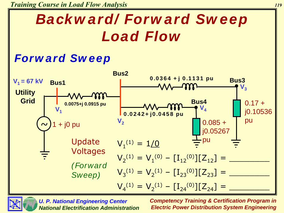
Backward/Forward Sweep Load Flow
Forward Sweep
Bus1Utility
Grid
Bus3
Bus4
V1 = 67 kV
V2
V4
V3
Bus2
~
V1
1 + j0 pu 0.085 + j0.05267 pu
0.17 + j0.10536 pu
0.0364 +j 0.1131 pu
0.0075+j 0.0915 pu
0.0242+j0.0458 pu
Update Voltages
(Forward Sweep)
V1(1) = 1/0
V2(1) = V1
(0) – [I12(0)][Z12] = ________
V3(1) = V2
(1) – [I23(0)][Z23] = ________
V4(1) = V2
(1) – [I24(0)][Z24] = ________
120
Competency Training & Certification Program in Electric Power Distribution System Engineering
U. P. National Engineering CenterNational Electrification Administration
Training Course in Load Flow Analysis
Backward/Forward Sweep Load Flow
Solving for Injected Power
Bus1Utility
Grid
Bus3
Bus4
V1 = 67 kV
V2
V4
V3
Bus2
~
V1
1 + j0 pu 0.085+ j0.05267 pu
0.17 + j0.10536 pu
Solve Injected Power
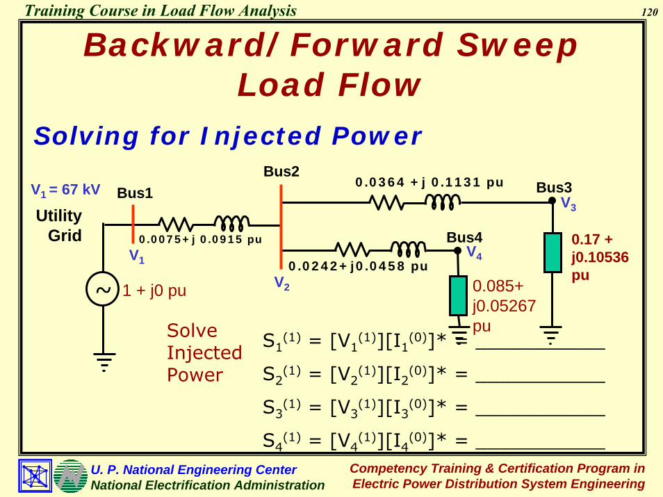
S1(1) = [V1
(1)][I1(0)]* = ___________
S2(1) = [V2
(1)][I2(0)]* = ___________
S3(1) = [V3
(1)][I3(0)]* = ___________
S4(1) = [V4
(1)][I4(0)]* = ___________
0.0364 +j 0.1131 pu
0.0075+j 0.0915 pu
0.0242+j0.0458 pu

121
Competency Training & Certification Program in Electric Power Distribution System Engineering
U. P. National Engineering CenterNational Electrification Administration
Training Course in Load Flow Analysis
Backward/Forward Sweep Load Flow
Solving for Power Mismatch
Bus1Utility
Grid
Bus3
Bus4
V1 = 67 kV
V2
V4
V3
Bus2
~
V1
1 + j0 pu 0.085 + j0.05267 pu
0.17 + j0.10536 pu
Solve Power Mismatch
∆S1(1) = S1
(sp) - S1(calc) = ____________
∆S2(1) = S2
(sp) – S2(calc) = ____________
∆S3(1) = S3
(sp) – S3(calc) = ____________
∆S4(1) = S4
(sp) – S4(calc) = ____________
0.0364 +j 0.1131 pu
0.0075+j 0.0915 pu
0.0242+j0.0458 pu

122
Competency Training & Certification Program in Electric Power Distribution System Engineering
U. P. National Engineering CenterNational Electrification Administration
Training Course in Load Flow Analysis
Backward/Forward Sweep Load Flow
Iterative Solution
Iteration 2:
I1(1) = 0
I2(1) = 0
I3(1) = S3* /[V3
(1)]* = __________
I4(1) = S4* /[V4
(1)]* = __________
Solve Injected Currents by Loads
I24(1) = I4
(1) = _______
I23(1) = I3
(1) = _______
I12(1) = 0 + I23
(1) + I24(1) = _______
Solve Line Currents
(Backward Sweep)

123
Competency Training & Certification Program in Electric Power Distribution System Engineering
U. P. National Engineering CenterNational Electrification Administration
Training Course in Load Flow Analysis
Backward/Forward Sweep Load Flow
Iterative Solution
Update Voltages
(Forward Sweep)
V1(2) = 1/0
V2(2) = V1
(1) – [I12(1)][Z12] = ________
V3(2) = V2
(1) – [I23(1)][Z23] = ________
V4(2) = V2
(1) – [I24(1)][Z24] = ________
S1(2) = [V1
(2)][I1(1)]* = ___________
S2(2) = [V2
(2)][I2(1)]* = ___________
S3(2) = [V3
(2)][I3(1)]* = ___________
S4(2) = [V4
(2)][I4(1)]* = ___________
Solve Injected Power

124
Competency Training & Certification Program in Electric Power Distribution System Engineering
U. P. National Engineering CenterNational Electrification Administration
Training Course in Load Flow Analysis
Backward/Forward Sweep Load Flow
Iterative Solution
Solve Power Mismatch
∆S1(2) = S1
(sp) - S1(calc) = ____________
∆S2(2) = S2
(sp) – S2(calc) = ____________
∆S3(2) = S3
(sp) – S3(calc) = ____________
∆S4(2) = S4
(sp) – S4(calc) = ____________
If Mismatch is higher than set convergence index, repeat the procedure (Backward-Forward Sweep) [Iteration 3]

125
Competency Training & Certification Program in Electric Power Distribution System Engineering
U. P. National Engineering CenterNational Electrification Administration
Training Course in Load Flow Analysis
Backward/Forward Sweep Load Flow
Iterative Solution
Iteration 3:
I1(2) = 0
I2(2) = 0
I3(2) = S3* /[V3
(2)]* = __________
I4(2) = S4* /[V4
(2)]* = __________
Solve Injected Currents by Loads
I24(2) = I4
(2) = _______
I23(2) = I3
(2) = _______
I12(2) = 0 + I23
(2) + I24(2) = _______
Solve Line Currents
(Backward Sweep)

126
Competency Training & Certification Program in Electric Power Distribution System Engineering
U. P. National Engineering CenterNational Electrification Administration
Training Course in Load Flow Analysis
Backward/Forward Sweep Load Flow
Iterative Solution
Update Voltages
(Forward Sweep)
V1(3) = 1/0
V2(3) = V1
(2) – [I12(2)][Z12] = ________
V3(3) = V2
(2) – [I23(2)][Z23] = ________
V4(3) = V2
(2) – [I24(2)][Z24] = ________
S1(3) = [V1
(3)][I1(2)]* = ___________
S2(3) = [V2
(3)][I2(2)]* = ___________
S3(3) = [V3
(3)][I3(2)]* = ___________
S4(3) = [V4
(3)][I4(2)]* = ___________
Solve Injected Power

127
Competency Training & Certification Program in Electric Power Distribution System Engineering
U. P. National Engineering CenterNational Electrification Administration
Training Course in Load Flow Analysis
Backward/Forward Sweep Load Flow
Iterative Solution
Solve Power Mismatch
∆S1(3) = S1
(3) - S1(2)
∆S2(3) = S2
(3) – S2(2) = ____________
∆S3(3) = S3
(3) – S3(2) = ____________
∆S4(3) = S4
(3) – S4(2) = ____________
If Mismatch is lower than set convergence index, compute power flows

128
Competency Training & Certification Program in Electric Power Distribution System Engineering
U. P. National Engineering CenterNational Electrification Administration
Training Course in Load Flow Analysis
Bus1
Utility Grid
Bus2Bus3
Bus4
Backward/Forward Sweep Load Flow
0.0364 +j 0.1131 pu
0.0075+j 0.0915 pu0.0242+j0.0458
Lumped Load A2 MVA 85%PFVOLTAGE PROFILE
V1 = ________
V2 = ________
V3 = ________
V4 = ________
Lumped Load B1 MVA 85%PF
INJECTED POWER
P1 + jQ1 = ________ + j ________
P2 + jQ2 = ________ + j ________
P3 + jQ3 = ________ + j ________
P4 + jQ4 = ________ + j ________
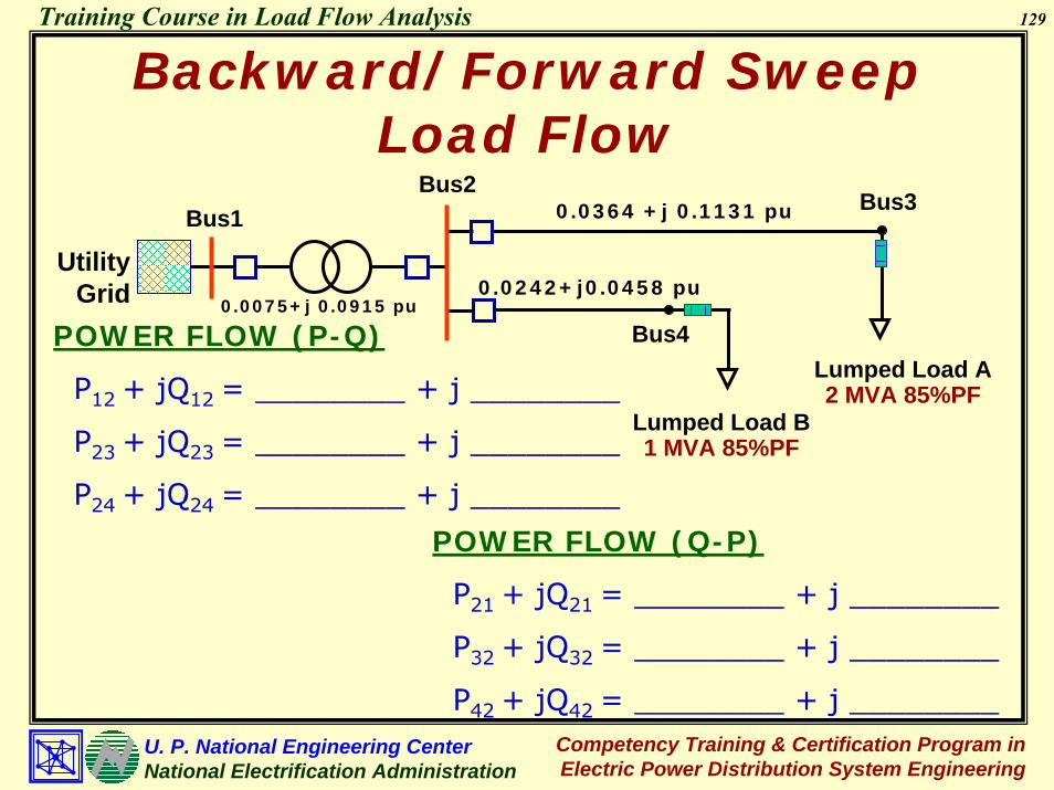
129
Competency Training & Certification Program in Electric Power Distribution System Engineering
U. P. National Engineering CenterNational Electrification Administration
Training Course in Load Flow Analysis
Bus2Bus3
Bus1
Utility Grid
Backward/Forward Sweep Load Flow
0.0364 +j 0.1131 pu
0.0075+j 0.0915 pu0.0242+j0.0458 pu
Bus4POWER FLOW (P-Q)
P12 + jQ12 = ________ + j ________
P23 + jQ23 = ________ + j ________
P24 + jQ24 = ________ + j ________
Lumped Load A2 MVA 85%PF
Lumped Load B1 MVA 85%PF
POWER FLOW (Q-P)
P21 + jQ21 = ________ + j ________
P32 + jQ32 = ________ + j ________
P42 + jQ42 = ________ + j ________

130
Competency Training & Certification Program in Electric Power Distribution System Engineering
U. P. National Engineering CenterNational Electrification Administration
Training Course in Load Flow Analysis
Backward/Forward Sweep Load Flow
Bus2Bus3
Bus1 0.0364 +j 0.1131 pu
0.0075+j 0.0915 pu0.0242+j0.0458 pu
Utility Grid
Bus4Branch Currents Lumped Load A
2 MVA 85%PFI12 = ________
I23 = ________
I24 = ________
Lumped Load B1 MVA 85%PF
POWER LOSSES
I2R12 + jI2X12 = ________ + j ________
I2R23 + jI2X24 = ________ + j ________
I2R24 + jI2X24 = ________ + j ________

131
Competency Training & Certification Program in Electric Power Distribution System Engineering
U. P. National Engineering CenterNational Electrification Administration
Training Course in Load Flow Analysis
Backward/Forward Sweep Load Flow
Line sections in the radial network are ordered by layers away from the root node (substation bus).
1 2 3
4 5 6
7 89 10 1211
13 14 15 1617 18 19 20
21 22 2324 25 26
3130292827
32 33 34
35
Layer 1
Layer 4
Layer 5
Layer 6
Layer 7
Layer 8
8
Layer 2
Layer 3

132
Competency Training & Certification Program in Electric Power Distribution System Engineering
U. P. National Engineering CenterNational Electrification Administration
Training Course in Load Flow Analysis
Three-Phase Forward/ Backward Sweep Method
The iterative algorithm for solving the radial system consists of three steps. At iteration k:
( )( )( )
)1k(
ic
ib
ia
*ic
*ib
*ia
)1k(icic
)1k(ibib
)1k(iaia
)k(
ic
ib
ia
VVV
YY
Y
V/SV/SV/S
III −
∗−
∗−
∗−
⎥⎥⎥
⎦
⎤
⎢⎢⎢
⎣
⎡
⎥⎥⎥
⎦
⎤
⎢⎢⎢
⎣
⎡
−
⎥⎥⎥⎥
⎦
⎤
⎢⎢⎢⎢
⎣
⎡
=⎥⎥⎥
⎦
⎤
⎢⎢⎢
⎣
⎡
Step 1: Nodal current calculation
icibia
icibia
icibia
icibia
Y,Y,YV,V,VS,S,S
I,I,IWhere, Current injections at node i
Scheduled power injections at node i
Voltages at node i
Admittances of all shunt elements at node i
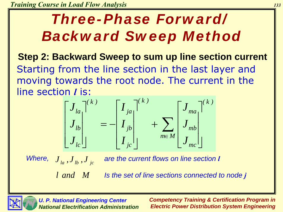
133
Competency Training & Certification Program in Electric Power Distribution System Engineering
U. P. National Engineering CenterNational Electrification Administration
Training Course in Load Flow Analysis
Three-Phase Forward/ Backward Sweep Method
Step 2: Backward Sweep to sum up line section current
∑∈ ⎥
⎥⎥
⎦
⎤
⎢⎢⎢
⎣
⎡+
⎥⎥⎥
⎦
⎤
⎢⎢⎢
⎣
⎡
−=⎥⎥⎥
⎦
⎤
⎢⎢⎢
⎣
⎡
Mm
)k(
mc
mb
ma
)k(
jc
jb
ja)k(
lc
lb
la
JJJ
III
JJJ
Starting from the line section in the last layer and moving towards the root node. The current in the line section l is:
jclbla J,J,JWhere, are the current flows on line section l
M and l Is the set of line sections connected to node j

134
Competency Training & Certification Program in Electric Power Distribution System Engineering
U. P. National Engineering CenterNational Electrification Administration
Training Course in Load Flow Analysis
Three-Phase Forward/ Backward Sweep Method
Step 3: Forward Sweep to update nodal voltageStarting from the first layer and moving towards the last layer, the voltage at node j is:
)k(
lc
lb
la
l,ccl,bcl,ac
l,bcl,bbl,ab
l,acl,abl,aa)k(
ic
ib
ia
)k(
jc
jb
ja
JJJ
zzzzzzzzz
VVV
VVV
⎥⎥⎥
⎦
⎤
⎢⎢⎢
⎣
⎡
⎥⎥⎥
⎦
⎤
⎢⎢⎢
⎣
⎡−
⎥⎥⎥
⎦
⎤
⎢⎢⎢
⎣
⎡=
⎥⎥⎥
⎦
⎤
⎢⎢⎢
⎣
⎡

135
Competency Training & Certification Program in Electric Power Distribution System Engineering
U. P. National Engineering CenterNational Electrification Administration
Training Course in Load Flow Analysis
Three-Phase Forward/ Backward Sweep Method
After the three steps are executed in one iteration, the power mismatches at each node for all phases are calculated:
( )( )( ) ic
2
ic*
ic)k(
ic)k(
ic)k(
ic
ib
2
ib*
ia)k(
ib)k(
ib)k(
ib
ia
2
ia*
ia)k(
ia)k(
ia)k(
ia
SVYIVS
SVYIVS
SVYIVS
−−=
−−=
−−=
∗
∗
∗
∆
∆
∆
If the real and imaginary part (real and reactive power) of any of these power mismatches is greater than a convergence criterion, steps 1, 2 & 3 are repeated until convergence is achieved.

136
Competency Training & Certification Program in Electric Power Distribution System Engineering
U. P. National Engineering CenterNational Electrification Administration
Training Course in Load Flow Analysis
Principles of Load Flow Control
Prime mover and excitation control of generatorsReactive Var Compensation (e.g., Capacitors)Control of tap-changing and voltage regulating transformers

137
Competency Training & Certification Program in Electric Power Distribution System Engineering
U. P. National Engineering CenterNational Electrification Administration
Training Course in Load Flow Analysis
Principles of Load Flow Control
Generator Voltage & Power Control
jXjX
IIEEii∠δ∠δ
VVtt∠∠00
The complex power delivered to the bus (Generator Terminal) is
~ [ ] [ ] ⎥⎦
⎤⎢⎣
⎡ ∠−∠∠=∠=+
jXVEVIVjQP ti
tttt000 * δ
⎥⎦⎤
⎢⎣⎡= δsin
XVEP ti
t ⎥⎦
⎤⎢⎣
⎡−=
XV
XVEQ tti
t
2
cosδ

138
Competency Training & Certification Program in Electric Power Distribution System Engineering
U. P. National Engineering CenterNational Electrification Administration
Training Course in Load Flow Analysis
Principles of Load Flow Control
Generator Voltage & Power Control
⎥⎦⎤
⎢⎣⎡= δsin
XVEP ti
t ⎥⎦
⎤⎢⎣
⎡−=
XV
XVEQ tti
t
2
cosδ
Observations:
1. Real Power is injected into the bus (Generator Operation), δ must be positive (Ei leads Vt)
2. Real Power is drawn from the bus (Motor Operation), δ must be negative (Ei lags Vt)
3. In actual operation, the numeric value of δ is small & since the slope of Sine function is maximum for small values, a minute change in δ can cause a substantial change in Pt

139
Competency Training & Certification Program in Electric Power Distribution System Engineering
U. P. National Engineering CenterNational Electrification Administration
Training Course in Load Flow Analysis
Principles of Load Flow Control
Generator Voltage & Power Control
⎥⎦⎤
⎢⎣⎡= δsin
XVEP ti
t ⎥⎦
⎤⎢⎣
⎡−=
XV
XVEQ tti
t
2
cosδ
Observations:
4. Reactive Power flow depends on relative values of EiCosδ and Vt
5. Since the slope of Cosine function is minimum for small values of angle, Reactive Power is controlled by varying Ei
• Over-excitation (increasing Ei) will deliver Reactive Power into the Bus
• Under-excitation (decreasing Ei) will absorb Reactive Power from the Bus

140
Competency Training & Certification Program in Electric Power Distribution System Engineering
U. P. National Engineering CenterNational Electrification Administration
Training Course in Load Flow Analysis
Principles of Load Flow Control
Capacitor Compensation
Ipqp
PL - jQL
q
+ jQc
~
p
qpq
p
qpqpq V
PXj
VQX
VE −−=
The voltage of bus q can be expressed as
Observations:
1. The Reactive Power Qq causes a voltage drop and thus largely affects the magnitude of Eq
2. A capacitor bank connected to bus q will reduce Qq that will consequently reduce voltage drop

141
Competency Training & Certification Program in Electric Power Distribution System Engineering
U. P. National Engineering CenterNational Electrification Administration
Training Course in Load Flow Analysis
Principles of Load Flow Control
Tap-Changing Transformera:1
q r
s p
The π equivalent circuit of transformer with the per unit transformation ratio:
pqya
a2
1−pqy
aa 1−
pqya1
Observation:
The voltage drop in the transformer is affected by the transformation ratio “a”

142
Competency Training & Certification Program in Electric Power Distribution System Engineering
U. P. National Engineering CenterNational Electrification Administration
Training Course in Load Flow Analysis
Uses of Load Flow Study
Sensitivity Analysis with Load Flow Study
Analysis of Existing Conditions
Analysis for Correcting PQ Problems
Expansion Planning
Contingency Analysis
System Loss Analysis

143
Competency Training & Certification Program in Electric Power Distribution System Engineering
U. P. National Engineering CenterNational Electrification Administration
Training Course in Load Flow Analysis
Uses of Load Flow StudiesSensitivity Analysis with Load Flow Study1) Take any line, transformer or generator out of service.2) Add, reduce or remove load to any or all buses.
3) Add, remove or shift generation to any bus.
4) Add new transmission or distribution lines.
5) Increase conductor size on T&D lines.
6) Change bus voltages.
7) Change transformer taps.
8) Increase or decrease transformer size.
9) Add or remove rotating or static var supply to buses.

144
Competency Training & Certification Program in Electric Power Distribution System Engineering
U. P. National Engineering CenterNational Electrification Administration
Training Course in Load Flow Analysis
Uses of Load Flow Studies
1) ANALYSIS OF EXISTING CONDITIONS• Check for voltage violations
PGC: 0.95 – 1.05 p.u. (For Transmission)PDC: 0.90 – 1.10 p.u (For Distribution)*
*Recommended 0.95 – 1.05 p.u.• Check for branch power flow violations
Transformer OverloadsLine Overloads
• Check for system lossesCaps on Segregated DSL

145
Competency Training & Certification Program in Electric Power Distribution System Engineering
U. P. National Engineering CenterNational Electrification Administration
Training Course in Load Flow Analysis
Uses of Load Flow Studies
2) ANALYSIS FOR CORRECTING PQ PROBLEMS
• Voltage adjustment by utility at delivery pointRequest TransCo to improve voltage at connection pointTransCo as System Operator will determine feasibility based on Economic Dispatch and other adjustments such as transformer tap changing and reactive power compensation

146
Competency Training & Certification Program in Electric Power Distribution System Engineering
U. P. National Engineering CenterNational Electrification Administration
Training Course in Load Flow Analysis
Uses of Load Flow Studies
2) ANALYSIS FOR CORRECTING PQ PROBLEMS
• Transformer tap changingAvailable Taps
At Primary SideAt Secondary SideBoth Sides
Typical Taps Tap 1: +5%Tap 2: +2.5%Tap 3: 0% (Rated Voltage)Tap 4: -2.5%Tap 5: -5%

147
Competency Training & Certification Program in Electric Power Distribution System Engineering
U. P. National Engineering CenterNational Electrification Administration
Training Course in Load Flow Analysis
Uses of Load Flow Studies
2) ANALYSIS FOR CORRECTING PQ PROBLEMS
•Capacitor compensation• Compensate for Peak Loading• Check overvoltages during Off-Peak• Optimize Capacitor Plan
• System configuration improvement

148
Competency Training & Certification Program in Electric Power Distribution System Engineering
U. P. National Engineering CenterNational Electrification Administration
Training Course in Load Flow Analysis
Uses of Load Flow Studies
3) EXPANSION PLANNING• New substation construction• Substation capacity expansion• New feeder segment construction / extension• Addition of parallel feeder segment• Reconducting of existing feeder segment/ circuit • Circuit conversion to higher voltage• Generator addition

149
Competency Training & Certification Program in Electric Power Distribution System Engineering
U. P. National Engineering CenterNational Electrification Administration
Training Course in Load Flow Analysis
Uses of Load Flow Studies
4) CONTINGENCY ANALYSIS
Reliability analysis of the Transmission (Grid) and Subtransmission System
5) SYSTEM LOSS ANALYSIS
Segregation of System Losses

150
Competency Training & Certification Program in Electric Power Distribution System Engineering
U. P. National Engineering CenterNational Electrification Administration
Training Course in Load Flow Analysis