load sharing report
DESCRIPTION
AUTOMATIC LOAD SHARING OF TRANSFORMERTRANSCRIPT
A
Synopsis Report
On
TITLE: AUTOMATIC LOAD SHARING OF TRANSFORMER
B.E. Electrical Egg.
ByJadhav Sushil k.
Phad Ramkrushna s.Khairnar Nitin e.Gaikwad Amol b.
Under the guidance of
Prof. A. M. LULHE
Department of Electrical Engineering,
GOKHALE EDUCATION SOCIETY’S
R. H. SAPAT. COLLEGE OF ENGINEERING, MANAGEMENT STUDIES &
RESEARCH, NASHIK.
ABSTRACT –
This project proposes the automatic load sharing of the transformer using microcontroller. The aim of this project is to share the load between the parallel running transformers safely and economically. It provides over load protection and reliability of supply system. The design of system using PIC microcontroller is described. In this project we have used PIC microcontroller based system and transformer with C.T. is used to determine current flowing through the each circuit. Microcontroller is used to make a necessary calculation so that switching of transformer for sharing the load can be done.
INTRODUCTION –
In this last decade use of electrical energy is increasing rapidly. So the distribution network of electric power is become wide. Transformer is the main part of the transmission and distribution network, therefore efficient use of transformer and continuity of supply is major considerations. It is found those distribution transformers are efficient when they are use at their rated capacity or full load. In the distribution system may transformer operated in parallel so it becomes necessary to use the transformer at their full capacity to reduced losses.
The automatic load sharing between the transformers provide the scope for efficient use of transformer using microcontroller based control circuit.
In this project “AUTOMATIC LOAD SHARING OF TRANSFORMERS” we are using two transformers, one is main transformer and the next is backup transformer. Here the load is directly connected to the secondary of the main transformer as well as backup transformer; here two transformers are connected through the relay.

BLOCK DIAGRAM:
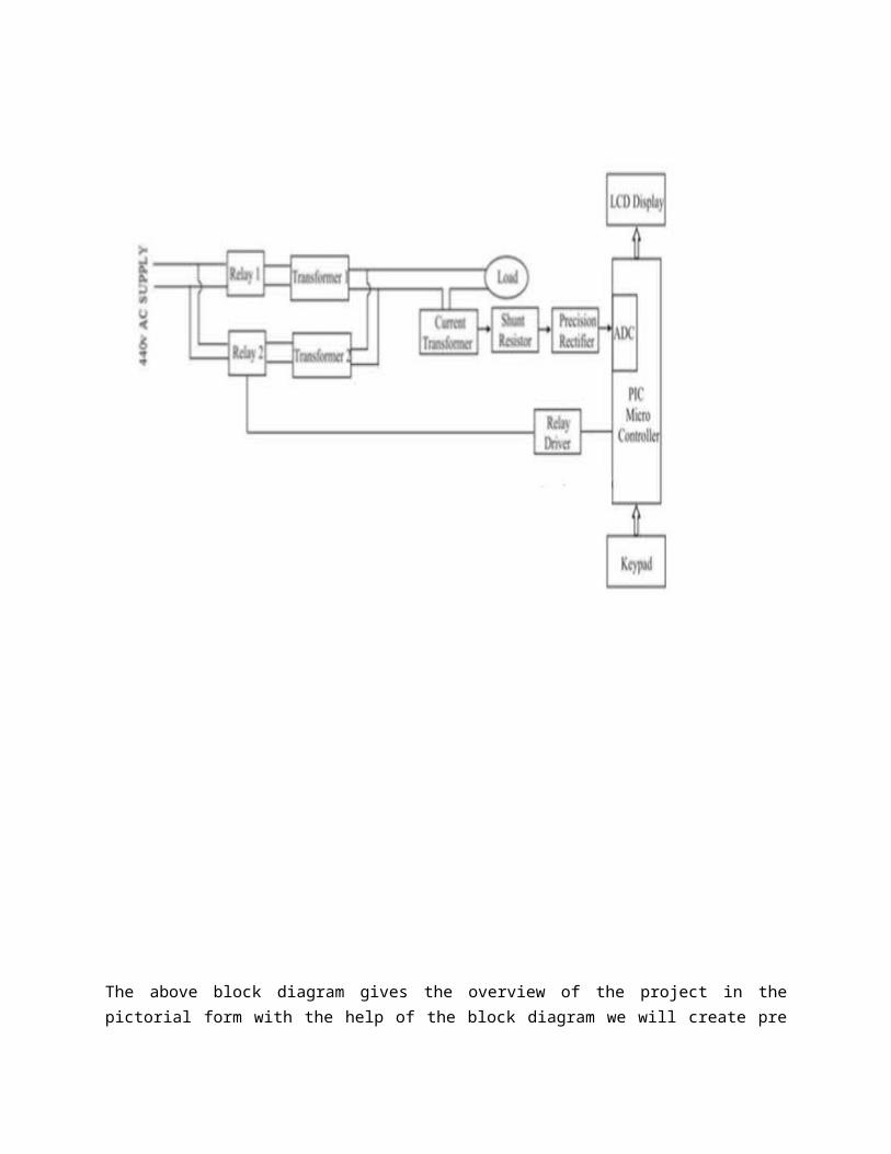
The above block diagram gives the overview of the project in the pictorial form with the help of the block diagram we will create pre model of the project and the analyze the function of the project the explanation of the project with block diagram over view is given as follows.
Power Supply Section:
This section is meant for supplying Power to all the sections mentioned above. It basically consists of a Transformer to step down the 230V ac to 18V ac followed by diodes. Here diodes are used to rectify the ac to dc. After rectification the obtained rippled dc is filtered using a capacitor Filter. A positive voltage regulator is used to regulate the obtained dc voltage.
Microcontroller Section:
This section forms the control unit of the whole project. This section basically consists of a Microcontroller with its associated circuitry like Crystal with capacitors, Reset circuitry, Pull up resistors (if needed) and so on. The Microcontroller forms the heart of the project because it controls the devices being interfaced and communicates with the devices according to the program being written.
Transformers:
In general, the ac line voltage present in your house wiring is not suitable for electronic circuits. Most circuits require a considerably lower voltage, while a few require higher voltages. The transformer serves to convert the ac line voltage to a voltage level more appropriate to the needs of the circuit to be powered. At the same time, the transformer provides electrical isolation between the ac line and the circuit being powered, which is an important safety consideration. However, a line transformer is generally large and heavy, and is rather expensive. Therefore, some power supplies (notably for PCs) are deliberately designed to operate directly from the ac line without a line transformer. The output of the transformer is still an ac voltage, but now of an appropriate magnitude for the circuit to be powered.
ADC:
Analog to digital (A/D, ADC) converters are electrical circuit devices that convert continuous signals, such as voltages or currents, from the analog domain to the digital domain where the signals are represented by numbers.
Sensors:
This part of the system consists of current sensor. These sensor sense various parameters of load- current and are then sent to the Analog to Digital Converter.
Relay:
In this project Relays are used to the Trip the transformer. A relay is an electrical switch that opens and closes under control of another electrical circuit. In the original form, the switch is operated by an electromagnet to open or close one or many sets of contact
ADVANTAGES –
1. Transformer losses are reduced.2. Continuity of supply can be maintained.3. Overload protection is given to transformer.4. Accident prevention 5. Transformer safety 6. Remove power blackout at a peak hour 7. It prevent circuitry from damage
Conclusion:
By implementing automatic load sharing project parallel operation of transformers is become efficient and economical. This project also helps in maintaining continuity of power supply by switching transformer load.
Reference-
Electrical technology vol. 3 by B. L. THAREJA
IEEE transaction on power electronics vol.19 no.6 Nov. 2004.