local exhaust ventilation (lev) guidance - hbe uk & … · • a hood of some kind, ... local...
TRANSCRIPT
Local Exhaust Ventilation (LEV) Guidance

Our vision: A country where worker safety, health and welfare and the safe management of chemicals are central to successful enterprise
Published in January 2014 by the Health & Safety Authority, The Metropolitan Building, James Joyce St., Dublin 1.
ContentsChapter 1 Summary . . . . . . . . . . . . . . . . . . . . . . . . . . . . . . . . . . . . . . . . . . . . . . . . . . . . . . . . . . . . . . . 2
Chapter 2 Introduction . . . . . . . . . . . . . . . . . . . . . . . . . . . . . . . . . . . . . . . . . . . . . . . . . . . . . . . . . . . . 4
Risk Assessment . . . . . . . . . . . . . . . . . . . . . . . . . . . . . . . . . . . . . . . . . . . . . . . . . . . . . 5
Control . . . . . . . . . . . . . . . . . . . . . . . . . . . . . . . . . . . . . . . . . . . . . . . . . . . . . . . . . . . . . . 5
Chapter 3 What is Local Exhaust Ventilation (LEV)? . . . . . . . . . . . . . . . . . . . . . . . . . . . . . . . . . . 7
Chapter 4 Types of Local Exhaust Ventilation (LEV) . . . . . . . . . . . . . . . . . . . . . . . . . . . . . . . . . 19
Chapter 5 Misconceptions . . . . . . . . . . . . . . . . . . . . . . . . . . . . . . . . . . . . . . . . . . . . . . . . . . . . . . . . 31
Chapter 6 Properties of Airborne Contaminants . . . . . . . . . . . . . . . . . . . . . . . . . . . . . . . . . . . 35
Chapter 7 Flow Rates . . . . . . . . . . . . . . . . . . . . . . . . . . . . . . . . . . . . . . . . . . . . . . . . . . . . . . . . . . . . . 38
Chapter 8 How to Select Local Exhaust Ventilation (LEV) . . . . . . . . . . . . . . . . . . . . . . . . . . . 40
Chapter 9 Installation and Maintenance of LEV . . . . . . . . . . . . . . . . . . . . . . . . . . . . . . . . . . . . 43
Chapter 10 Information and Training for Employees . . . . . . . . . . . . . . . . . . . . . . . . . . . . . . . . 47
Chapter 11 Keeping Records . . . . . . . . . . . . . . . . . . . . . . . . . . . . . . . . . . . . . . . . . . . . . . . . . . . . . . . 49
Chapter 12 Examining & Monitoring Performance . . . . . . . . . . . . . . . . . . . . . . . . . . . . . . . . . . 50
Chapter 13 Main Legal Requirements . . . . . . . . . . . . . . . . . . . . . . . . . . . . . . . . . . . . . . . . . . . . . . . 57
Chapter 14 Standards . . . . . . . . . . . . . . . . . . . . . . . . . . . . . . . . . . . . . . . . . . . . . . . . . . . . . . . . . . . . . . 61
Chapter 15 References . . . . . . . . . . . . . . . . . . . . . . . . . . . . . . . . . . . . . . . . . . . . . . . . . . . . . . . . . . . . . 62
Chapter 16 Further Reading . . . . . . . . . . . . . . . . . . . . . . . . . . . . . . . . . . . . . . . . . . . . . . . . . . . . . . . . 63
Chapter 17 Useful Contacts . . . . . . . . . . . . . . . . . . . . . . . . . . . . . . . . . . . . . . . . . . . . . . . . . . . . . . . . 64
Chapter 18 Glossary . . . . . . . . . . . . . . . . . . . . . . . . . . . . . . . . . . . . . . . . . . . . . . . . . . . . . . . . . . . . . . . . 65
Drawings/pictures/diagrams courtesy of the HSE/HSL UK & IOSH
2 Chapter 1
This guidance is written for employers, managers, employees and their safety representatives and those who provide, install and maintain local exhaust ventilation (LEV) systems.
In preventing exposure to harmful substances in the workplace, there is a hierarchy of control measures that must be considered, commencing with the elimination or substitution of the hazard or, where these options are not possible, the hazard must be controlled by engineering means. Local exhaust ventilation (LEV) is one such engineering control measure.
LEV is an engineering system designed to reduce employee exposure to airborne contaminants (dust, mist, fume, vapour, gas) in the workplace by capturing the emission at source and transporting it to a safe emission point or to a filter/scrubber. Employers need to work with designers, suppliers, installers and employees to effectively control exposure to airborne contaminants.
Suppliers must provide LEV that is fit for purpose, is shown to work and continues to work.
The employer (the LEV owner) must ensure controls are adequate. Everyone, including suppliers and users of the LEV, must be competent in the use of the LEV system.
The main LEV elements are:
• A hood of some kind, where the contaminants enter the system
• Ducting, which safely transports the contaminants to a filter/cleaner/exhaust point
• Air cleaner/filter/scrubber
• Air mover: a fan to power the system
• Discharge: a safe point of air exhaust
When using LEV to control exposure, the employer must thoroughly assess the hazards to be controlled and be satisfied with the following: the LEV system is fit for purpose; it is being used correctly by trained employees; the system is regularly maintained to remain effective; and records are kept to demonstrate the system is both effective and ongoing. Having a good understanding of what hazards need to be controlled is crucial to ensure that the initial design is capable of achieving adequate control.
Cyan 100%Magenta 76%Yellow 0Black 27%
Local Exhaust Ventilation (LEV) Guidance
Chapter 1 Summary
When installing LEV:
• Identify and assess the hazard(s) to be controlled
• Identify competent contractors to install the system
• Provide the installer with clear requirements or specifications
• Review and ensure that the design and its specifications are satisfactory
• Obtain and retain all the related paperwork in design specifications, including the commissioning report (hand book)
• Ensure when the system is installed that it meets the design specifications
• Maintain the system and measure performance regularly
• Train employees in the proper use of the LEV
3Chapter 1
Cyan 100%Magenta 76%Yellow 0Black 27%
Local Exhaust Ventilation (LEV) Guidance
Chapter 2 Introduction
Local exhaust ventilation (LEV) is an engineering system frequently used in the workplace to protect employees from hazardous substances. To have an effective system it is important that it is well designed and installed, used correctly and properly maintained. All the participants, from designer to end-user need to work together to provide an effective system.
Common Problems
• Employers are often unaware their employees are being over-exposed to hazardous substances or that existing controls may be inadequate
• Sources of exposure are missed
• Employers (and suppliers) are over-optimistic about the effectiveness of the controls
• Existing controls have deteriorated
• Controls are not used correctly
Employers need to work with designers, suppliers and employees to ensure effective control, to avoid expensive mistakes and to control exposure effectively. Suppliers must provide LEV that is fit for purpose, is shown to work and continues to work. The employer (the LEV owner) must ensure controls are adequate. Everyone, both suppliers and users of the LEV, must be competent in the operation of the LEV system.
Adverse health effects can occur when employees are exposed to occupational hazards such as dusts, fumes and vapours (chemical or biological agents). The effects of exposure to a hazard depend on the frequency, duration and degree of exposure: some substances can cause immediate health effects, such as carbon monoxide poisoning; others, such as asbestos, can have a long latency period. The potential for exposure to any chemical or biological agent needs to be assessed in each place of work.
Employees can contract occupational illnesses and diseases and develop these because they breathe in too much dust, fumes or other airborne contaminants at work, often because control measures are not in place or do not work well enough. Many industries can be affected, including chemical processing, pharmaceutical, biotechnology, woodworking, welding, paint-spraying, stonemasonry, engineering and foundry work. The purpose of this guidance is to describe how to control gas, vapour, dust, fume, mist, in other words aerosols (hazardous agents), in the workplace air by using local exhaust ventilation (LEV), i.e. extracting the contaminant and preventing exposure.
Cyan 100%Magenta 76%Yellow 0Black 27%
Local Exhaust Ventilation (LEV) Guidance
4 Chapter 2
Although this guide concentrates on local exhaust ventilation (LEV), it is important to remember that the control or lack of general ventilation, including general supply and exhaust ventilation, can affect the performance of the LEV. For instance, a draught from an open door may challenge a welding hood extraction performance, or an insufficient supply of air in a closed system will ‘starve’ an exhausting LEV system. Therefore there are many factors that need to be considered when installing controls.
Risk Assessment
A risk assessment involves (1) anticipating; (2) recognising; (3) evaluating; and (4) controlling the hazards to which the employee might be exposed. The Authority has advice on its website (www.hsa.ie) on how to carry out an assessment.
When the employer has completed a risk assessment, evaluated the risks and determined the potential hazards, control methods need to be considered. As well as health hazards, there may be flammability, reactivity and/or physical hazards (e.g. excessive heat).
Control
When control is being considered there is a standard hierarchical approach. Can the process be changed so that the hazardous chemical agent can be eliminated or substituted with a less hazardous one? Can the process be modified to reduce risk of exposure (for example can the process temperature be lowered to reduce vapour release)? Are engineering controls appropriate? Can structures such as hoods, booths, enclosures or local exhaust ventilation be used to contain or capture hazardous chemical agent emissions? Administrative controls are used to minimise employee exposure by time planning and rotation. The final control in the hierarchy is the use of personal protective equipment (PPE).
Cyan 100%Magenta 76%Yellow 0Black 27%
Local Exhaust Ventilation (LEV) Guidance
5Chapter 2
In installing controls, the employer should start at the top of the hierarchy before rushing to install local exhaust ventilation (LEV), for example. The employer must first determine what is the most effective controls measure(s). The installation of any control measure is likely to be expensive (it has, for example, the potential to introduce operational difficulties), so a thorough review of the effectiveness of the chosen control method and how employees will interface with the system is vital.
The LEV system must be fit for purpose. For example, where the process entails grinding, it is likely that dust will be propelled from the source and the system needs to be designed to contain and capture the fugitive dust. Before designing or installing an LEV system, a good understanding of contaminants and the process demands are necessary. Consideration should be given as to whether the system will be required to cope with changing materials processes and, if so, whether you need to build in flexibility for this from the start.
The installation of new engineering controls such as LEV may bring its own risks and should be included in the overall assessment of operations. How well does the LEV system interface with the employee, the process and the place of work? For example, the noise generated by new fans/motors may need to be considered to prevent over-exposure to noise in the workplace; manual handling or ergonomic difficulties may be introduced; it may result in the generation of static electricity because of material type; or lack of bonding/earthing may be an ignition source.
Once the system is installed as designed, it must be used correctly and not tampered with; it must be regularly performance checked so that its effectiveness in protecting the employee(s) is achieved and must be maintained as laid down in the risk assessment.
In some circumstances, such as woodworking machines, the LEV may be designed as an integral part of the equipment. Therefore, although the design stage is completed in advance, employee training must be applied in all other elements, such as proper use, cleaning and maintenance.
Cyan 100%Magenta 76%Yellow 0Black 27%
Local Exhaust Ventilation (LEV) Guidance
6 Chapter 2
Chapter 3 What is Local Exhaust Ventilation (LEV)?
In its simplest terms local exhaust ventilation is an engineering system to protect employees from exposure to hazardous substances by containing or capturing them locally, at the emission point. Local exhaust ventilation (LEV) is only one of many engineering control options that may be used to remove and prevent employee exposure to vapour, mist, dust or other airborne contaminants. To be effective in protecting the employee(s), it is important that it is of good design, is fit for purpose, is regularly maintained and the system’s performance is monitored. Failure to do so can lead to employees being exposed because they have the impression that the system is effective when it is not.
Poor design and/or maintenance may lead, for example, to leakage in the workplace, causing concentrated local exposure rather than preventing it. A poorly designed, installed, misused and incorrectly maintained system can become an expensive waste of expenditure and may give a false impression of hazard control.
Employees must be given training in its use and maintenance to understand its correct use and effectiveness. Many employers and employees overestimate the effectiveness of the different types of LEV, and have a poor understanding of the types of conditions that could lead to a reduction in or depletion of the LEV’s effectiveness.
Cyan 100%Magenta 76%Yellow 0Black 27%
Local Exhaust Ventilation (LEV) Guidance
7Chapter 3
Good design and fit for purpose
Good design and being fit for purpose are the crucial initial considerations to ensure the effectiveness of the system. Where the process changes and additions or changes are needed the overall design should be reconsidered so the system remains effective. Creeping additions and extensions of the system can be a temptation for expediency, but lead to totally ineffective systems. If a system is redesigned, it also needs to be re-commissioned.
Examples of poor design:
• The extract fan system is sized too small and the hood cannot contain or capture the contaminants.
• The fume hood is placed in an area where there is sporadic cross draughts or insufficient supply air and the inward flow is challenged.
• A hood may have been designed without proper consideration of the work being done; the fit is incorrect and it may be impossible for the employee to use the system effectively; it may introduce ergonomic or manual-handling hazards.
Cyan 100%Magenta 76%Yellow 0Black 27%
Local Exhaust Ventilation (LEV) Guidance
8 Chapter 3
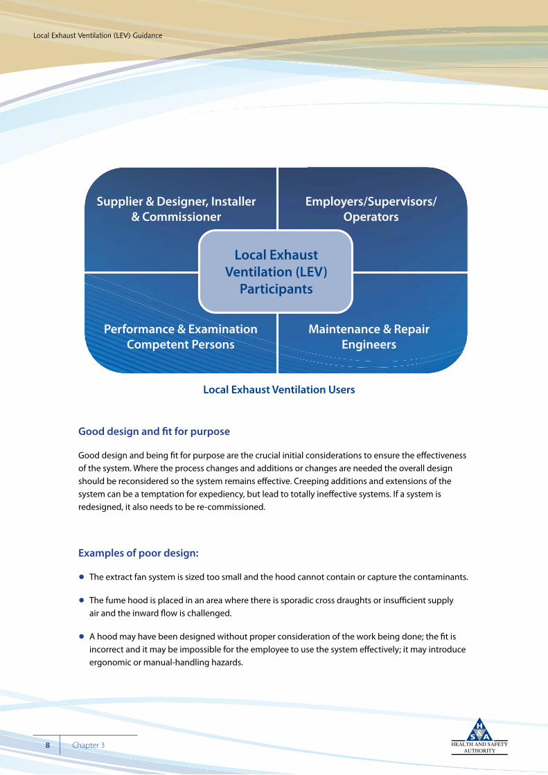
Local Exhaust Ventilation Users
Supplier & Designer, Installer& Commissioner
Employers/Supervisors/Operators
Maintenance & RepairEngineers
Performance & ExaminationCompetent Persons
Local ExhaustVentilation (LEV)
Participants Local Exhaust Ventilation Users
Supplier & Designer, Installer& Commissioner
Employers/Supervisors/Operators
Maintenance & RepairEngineers
Performance & ExaminationCompetent Persons
Local ExhaustVentilation (LEV)
Participants
• A fan may be incorrectly placed so that a major section of the ducting is under positive pressure. Where this ducting is within the workplace, any leakage on the positive pressure side has the potential to expose employees who may or may not be involved in the process and may be unaware of their exposure.
• Where ducting is wrongly sized, the transport velocity within the duct may be insufficient and contaminant will settle out in the ducting. This can be a serious fire hazard if combustible or flammable contaminants are being extracted.
• Flammable vapours/materials are being extracted but no consideration has been given to the prevention of a source of ignition or to dilution well below the lower explosion limit.
• Poor design of exhaust point may cause the contaminants to be captured by the air supply system; for example, instead of being exhausted and diluted, they may enter a downdraught caused by adjacent buildings and re-enter the workplace.
Cyan 100%Magenta 76%Yellow 0Black 27%
Local Exhaust Ventilation (LEV) Guidance
9Chapter 3
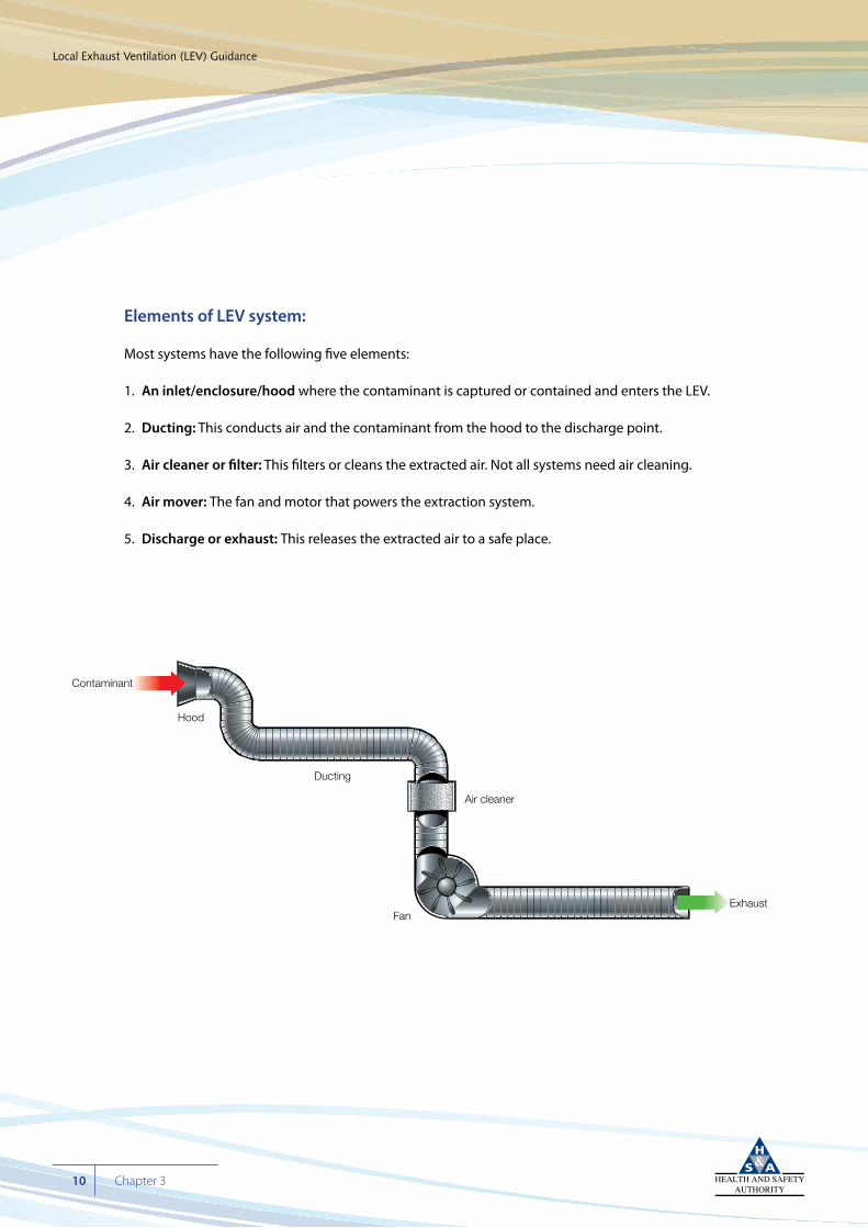
Elements of LEV system:
Most systems have the following five elements:
1. An inlet/enclosure/hood where the contaminant is captured or contained and enters the LEV.
2. Ducting: This conducts air and the contaminant from the hood to the discharge point.
3. Air cleaner or filter: This filters or cleans the extracted air. Not all systems need air cleaning.
4. Air mover: The fan and motor that powers the extraction system.
5. Discharge or exhaust: This releases the extracted air to a safe place.
Cyan 100%Magenta 76%Yellow 0Black 27%
Local Exhaust Ventilation (LEV) Guidance
10 Chapter 3
Hood
Contaminant
Ducting
FanExhaust
Air cleaner
The unit in its entirety must be of good design.
For example:
• Leak-proof: leakage on the suction or negative pressure side of the air remover will lead to inefficient extraction and leakage on the positive pressure side and may reintroduce the contaminant to the workplace.
• The flow rate of air through the system must be sufficient to achieve the initial capture/ containment and carry all contaminants to the purifying/filtering system (transport velocity). Combustible dusts (wood dust, for example), if not extracted properly, can deposit in the ducting and be a fire or explosion risk. Flammable solvents being captured by the system need to be diluted by sufficient air flow to prevent the formation of a flammable mixture.
• The ducting needs to be structured so as to avoid eddy currents and inefficient flow. For example, it should not have sharp right-angled turns, as this leads to dead areas with no flow.
• The construction and materials of construction need to be compatible with the contaminants being extracted. For example, where flammable gases or vapours are being extracted, the system should not be able to generate a source of ignition. Likely ignition sources could arise from the use of non-rated electrical equipment such as the air mover, or from the accumulation of static electricity from the lack of earthing and bonding and the use of non-conductive materials. Corrosion by the contaminants is another consideration.
Cyan 100%Magenta 76%Yellow 0Black 27%
Local Exhaust Ventilation (LEV) Guidance
11Chapter 3
1. An Inlet/Enclosure/Hood includes some type of hood or enclosure such as those listed below:
a. cowl for capturing welding fumes
b. laboratory fume hood or cupboard
c. biological safety cabinet
d. paint-spray booth
e. down-flow booth
f. ventilated hopper
g. dust-capturing device at woodworking machine
h. pouring station
i. movable/flexible hoods
j. portable hoods with filters
k. abrasive blasting room or cabinet
Cyan 100%Magenta 76%Yellow 0Black 27%
Local Exhaust Ventilation (LEV) Guidance
12 Chapter 3
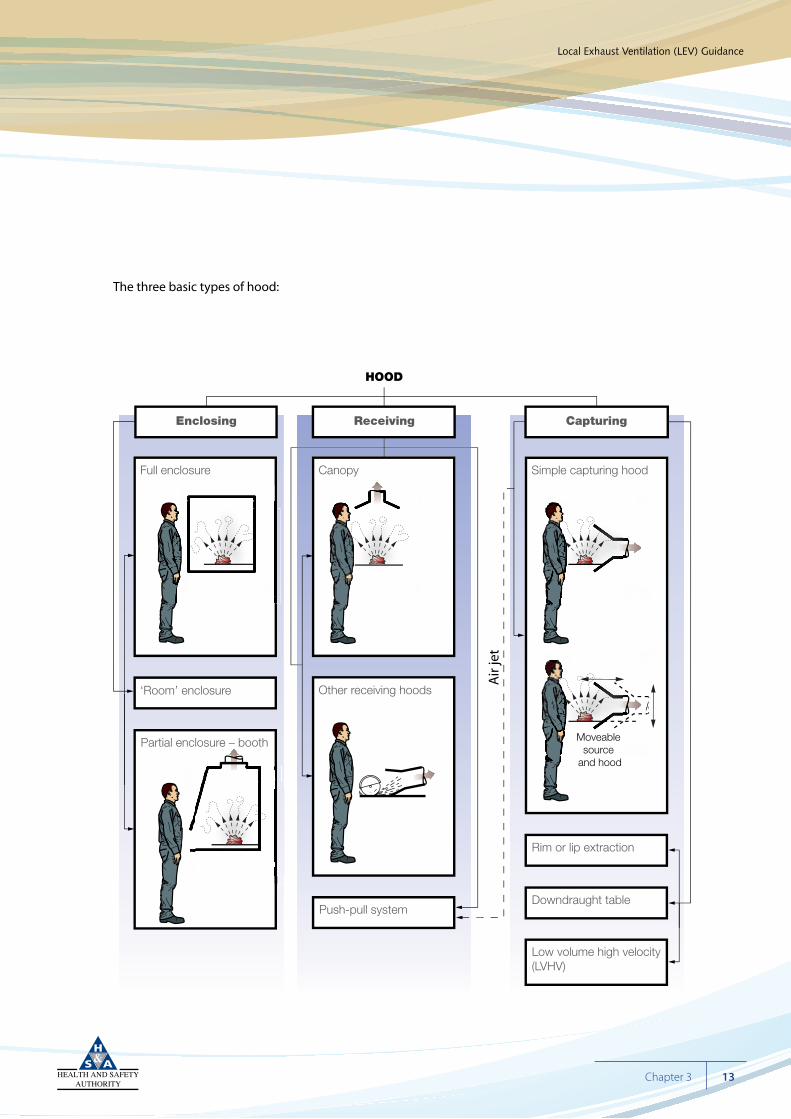
The three basic types of hood:
Cyan 100%Magenta 76%Yellow 0Black 27%
Local Exhaust Ventilation (LEV) Guidance
13Chapter 3
Enclosing Receiving Capturing
HOOD
Air
jet
Full enclosure
‘Room’ enclosure
Canopy
Push-pull system
Rim or lip extraction
Downdraught table
Low volume high velocity(LVHV)
Simple capturing hood
Other receiving hoods
Partial enclosure – booth Moveable source
and hood
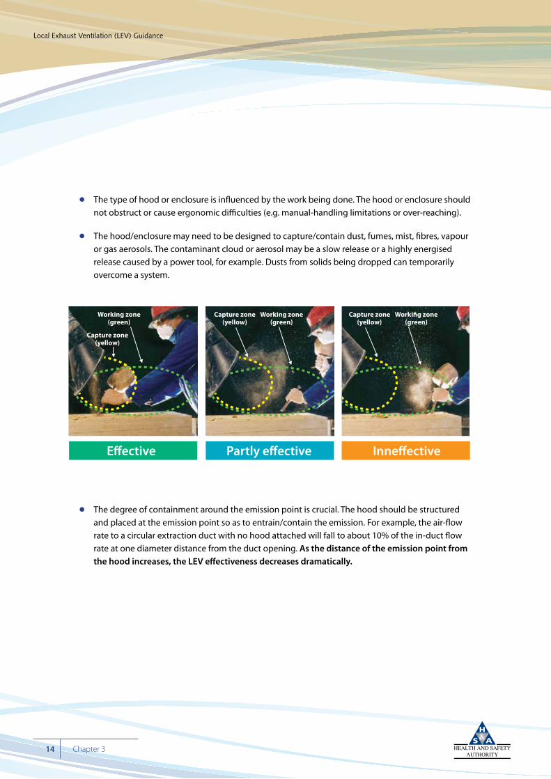
• The type of hood or enclosure is influenced by the work being done. The hood or enclosure should not obstruct or cause ergonomic difficulties (e.g. manual-handling limitations or over-reaching).
• The hood/enclosure may need to be designed to capture/contain dust, fumes, mist, fibres, vapour or gas aerosols. The contaminant cloud or aerosol may be a slow release or a highly energised release caused by a power tool, for example. Dusts from solids being dropped can temporarily overcome a system.
• The degree of containment around the emission point is crucial. The hood should be structured and placed at the emission point so as to entrain/contain the emission. For example, the air-flow rate to a circular extraction duct with no hood attached will fall to about 10% of the in-duct flow rate at one diameter distance from the duct opening. As the distance of the emission point from the hood increases, the LEV effectiveness decreases dramatically.
Cyan 100%Magenta 76%Yellow 0Black 27%
Local Exhaust Ventilation (LEV) Guidance
14 Chapter 3
Working zone(green)
Capture zone(yellow)
Working zone(green)
Capture zone(yellow)
Working zone(green)
Capture zone(yellow)
E�ective Partly e�ective Inne�ective
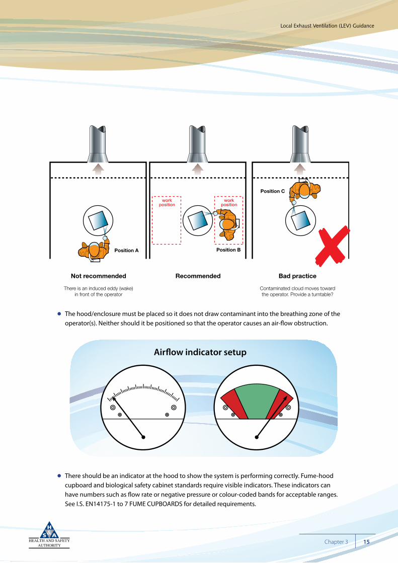
• The hood/enclosure must be placed so it does not draw contaminant into the breathing zone of the operator(s). Neither should it be positioned so that the operator causes an air-flow obstruction.
• There should be an indicator at the hood to show the system is performing correctly. Fume-hood cupboard and biological safety cabinet standards require visible indicators. These indicators can have numbers such as flow rate or negative pressure or colour-coded bands for acceptable ranges. See I.S. EN14175-1 to 7 FUME CUPBOARDS for detailed requirements.
Cyan 100%Magenta 76%Yellow 0Black 27%
Local Exhaust Ventilation (LEV) Guidance
15Chapter 3
8
Air�ow indicator setup
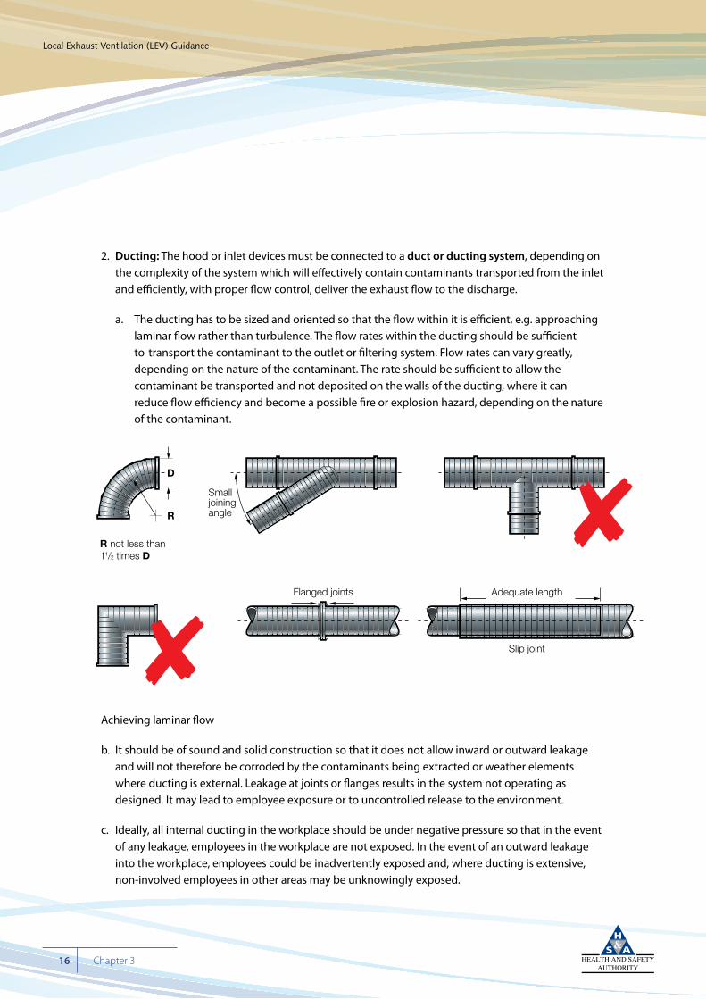
2. Ducting: The hood or inlet devices must be connected to a duct or ducting system, depending on the complexity of the system which will effectively contain contaminants transported from the inlet and efficiently, with proper flow control, deliver the exhaust flow to the discharge.
a. The ducting has to be sized and oriented so that the flow within it is efficient, e.g. approaching laminar flow rather than turbulence. The flow rates within the ducting should be sufficient to transport the contaminant to the outlet or filtering system. Flow rates can vary greatly, depending on the nature of the contaminant. The rate should be sufficient to allow the contaminant be transported and not deposited on the walls of the ducting, where it can reduce flow efficiency and become a possible fire or explosion hazard, depending on the nature of the contaminant.
Achieving laminar flow
b. It should be of sound and solid construction so that it does not allow inward or outward leakage and will not therefore be corroded by the contaminants being extracted or weather elements where ducting is external. Leakage at joints or flanges results in the system not operating as designed. It may lead to employee exposure or to uncontrolled release to the environment.
c. Ideally, all internal ducting in the workplace should be under negative pressure so that in the event of any leakage, employees in the workplace are not exposed. In the event of an outward leakage into the workplace, employees could be inadvertently exposed and, where ducting is extensive, non-involved employees in other areas may be unknowingly exposed.
Cyan 100%Magenta 76%Yellow 0Black 27%
Local Exhaust Ventilation (LEV) Guidance
16 Chapter 3
R not less than11/2 times D
Flanged joints
Smalljoiningangle
D
R
Adequate length
Slip joint
8
8
3. Air filtering, collection or cleaning system:
The contamination removal/filtering system should be fit for purpose. The type of system used will be very much dictated by the type of contaminant being extracted and can vary from a simple filter system to a multi-component system with pre-filters and scrubbers, for example. Whatever the filtering system, it should be designed so that it can cope with the contaminant load and remove/filter it effectively without affecting flow performance. It should be easily changed, cleaned and maintained without causing exposure to operations or maintenance staff. Following risk assessment, because of the increased potential for exposure and depending on the type and complexity of the filtering system, it may be necessary to draw up procedures for safe entry to filter housing, and for regular changing, cleaning and maintenance of filters.
4. Air mover or fan:
The air mover needs to be suitable for use. It will need to provide a sufficient air-flow rate to efficiently extract the contaminant, including a sufficient in-duct velocity to transport the contaminant to the cleaning/filtering system and prevent flammable material, for example, depositing within the ducting. The air mover should be able to cope with increased pressure as the filtering element becomes loaded.
The air mover should not provide a source of ignition. The air mover and its components should be impervious to corrosion/abrasion damage by the contaminants.
5. Discharge system:
The discharge ducting should be placed so that it does not affect any air-supply system. The air being exhausted should not be entrained and recirculated into the workplace through the air- supply system.
Cyan 100%Magenta 76%Yellow 0Black 27%
Local Exhaust Ventilation (LEV) Guidance
17Chapter 3
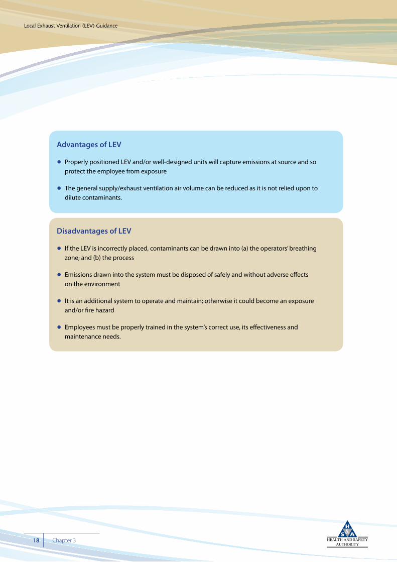
Advantages of LEV
• Properly positioned LEV and/or well-designed units will capture emissions at source and so protect the employee from exposure
• The general supply/exhaust ventilation air volume can be reduced as it is not relied upon to dilute contaminants.
Disadvantages of LEV
• If the LEV is incorrectly placed, contaminants can be drawn into (a) the operators’ breathing zone; and (b) the process
• Emissions drawn into the system must be disposed of safely and without adverse effects on the environment
• It is an additional system to operate and maintain; otherwise it could become an exposure and/or fire hazard
• Employees must be properly trained in the system’s correct use, its effectiveness and maintenance needs.
Cyan 100%Magenta 76%Yellow 0Black 27%
Local Exhaust Ventilation (LEV) Guidance
18 Chapter 3
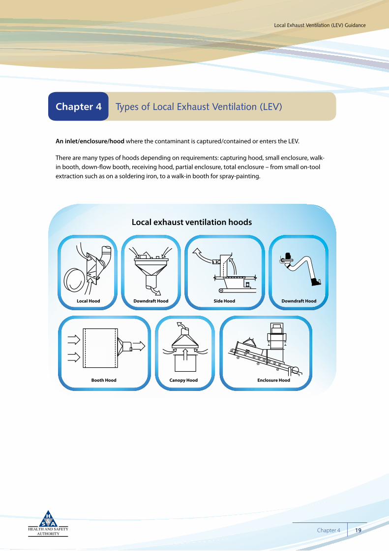
An inlet/enclosure/hood where the contaminant is captured/contained or enters the LEV.
There are many types of hoods depending on requirements: capturing hood, small enclosure, walk-in booth, down-flow booth, receiving hood, partial enclosure, total enclosure – from small on-tool extraction such as on a soldering iron, to a walk-in booth for spray-painting.
Cyan 100%Magenta 76%Yellow 0Black 27%
Local Exhaust Ventilation (LEV) Guidance
19Chapter 4
Chapter 4 Types of Local Exhaust Ventilation (LEV)
Local Hood Downdraft Hood Side Hood
Booth Hood Canopy Hood Enclosure Hood
Downdraft Hood
Local exhaust ventilation hoods
Cyan 100%Magenta 76%Yellow 0Black 27%
Local Exhaust Ventilation (LEV) Guidance
20 Chapter 4
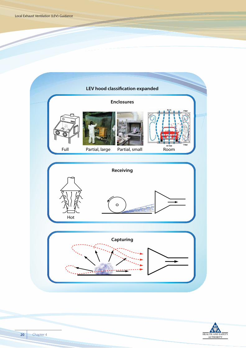
Capturing
Receiving
Hot
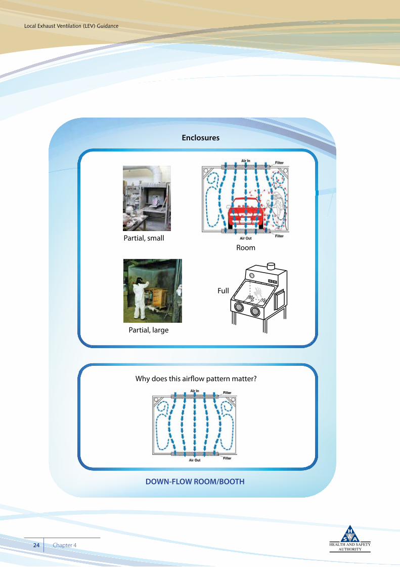
Enclosures
LEV hood classi�cation expanded
Full RoomPartial, large Partial, small
Cyan 100%Magenta 76%Yellow 0Black 27%
Local Exhaust Ventilation (LEV) Guidance
21Chapter 4
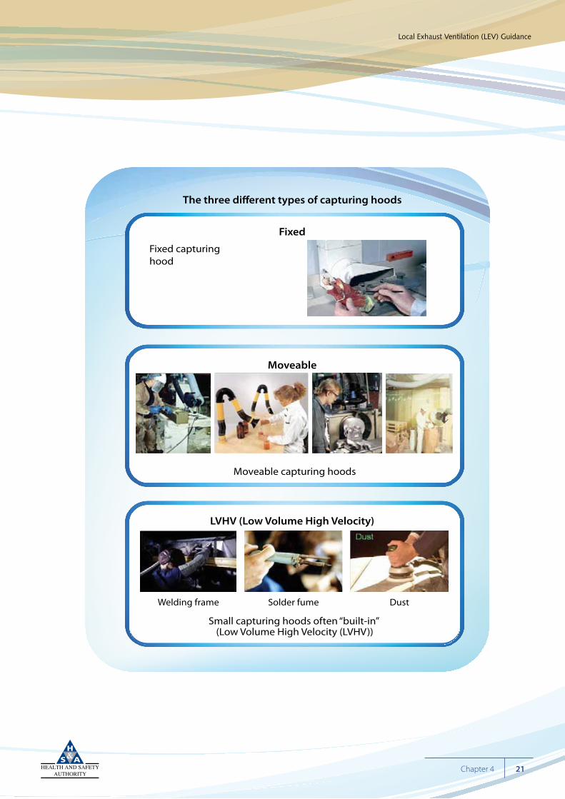
LVHV (Low Volume High Velocity)
Moveable
Fixed
The three di�erent types of capturing hoods
Fixed capturinghood
Moveable capturing hoods
Small capturing hoods often “built-in” (Low Volume High Velocity (LVHV))
Welding frame Solder fume Dust
Cyan 100%Magenta 76%Yellow 0Black 27%
Local Exhaust Ventilation (LEV) Guidance
22 Chapter 4
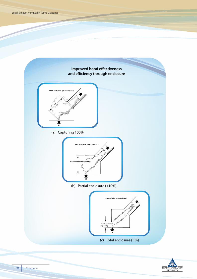
Improved hood e�ectivenessand e�ciency through enclosure
(a) Capturing 100%
(b) Partial enclosure (<10%)
(c) Total enclosure ( 1%)˜
X
1600 cu.ft/min. (0.755m/sec.)3
12
(305)
X
150 cu.ft/min. (0.071m/sec.)
12 (305) square opening
3
4 (102) squareopening
17 cu.ft/min. (0.008m/sec.)3
X
Cyan 100%Magenta 76%Yellow 0Black 27%
Local Exhaust Ventilation (LEV) Guidance
23Chapter 4
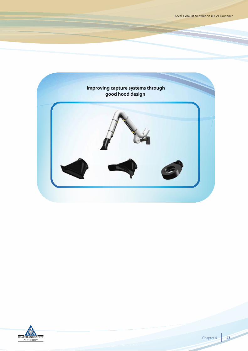
Improving capture systems throughgood hood design
Cyan 100%Magenta 76%Yellow 0Black 27%
Local Exhaust Ventilation (LEV) Guidance
24 Chapter 4
Enclosures
Room
Partial, large
Partial, small
Full
Why does this air�ow pattern matter?
DOWN-FLOW ROOM/BOOTH
Cyan 100%Magenta 76%Yellow 0Black 27%
Local Exhaust Ventilation (LEV) Guidance
25Chapter 4
DOWN-FLOW ROOM/BOOTH
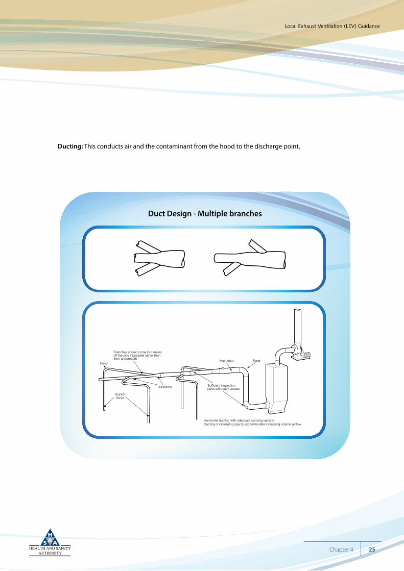
Duct Design - Multiple branches
Bend
Branchducts
Junctions
Branches should come into mainsoff the side if possible rather thanfrom underneath
Main duct Bend
Sufficient inspectionports with easy access
Horizontal ducting with adequate carrying velocity.Ducting of increasing size to accommodate increasing volume airflow.
Ducting: This conducts air and the contaminant from the hood to the discharge point.
The ducting needs to be sized correctly to carry flow and should be oriented in such a way as to prevent turbulence. It must be of sound and solid construction (See previous chapter).
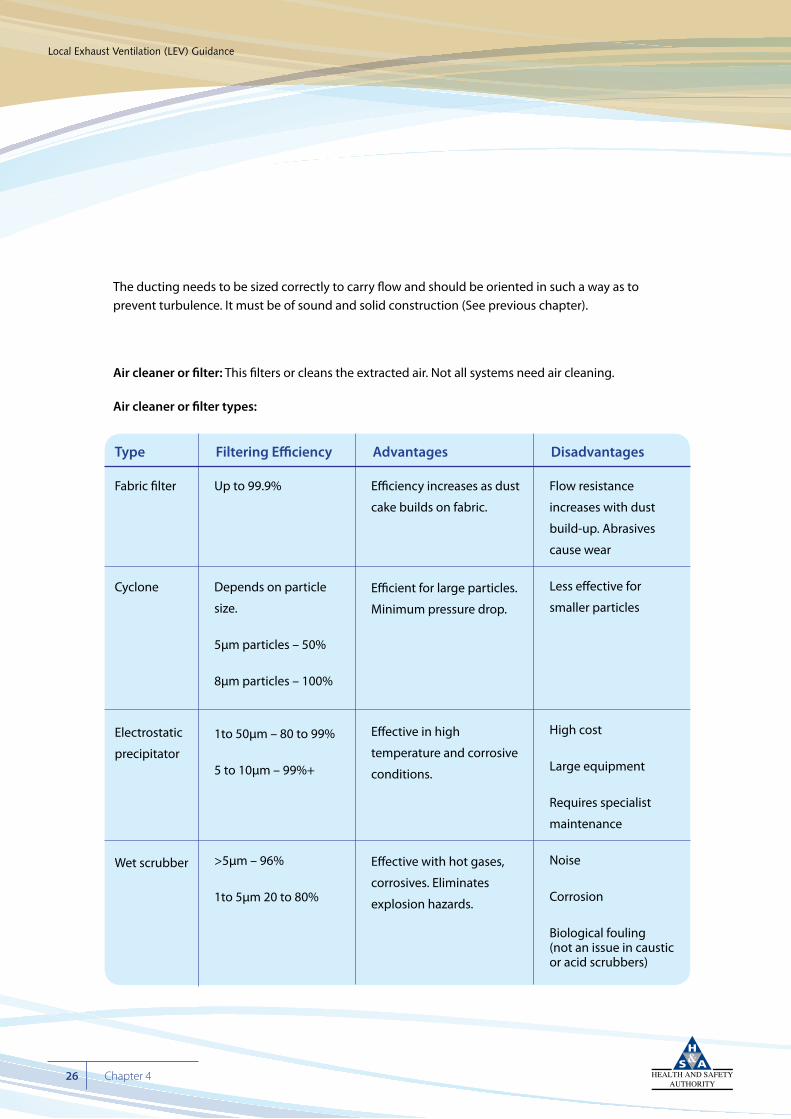
Air cleaner or filter: This filters or cleans the extracted air. Not all systems need air cleaning.
Air cleaner or filter types:
Cyan 100%Magenta 76%Yellow 0Black 27%
Local Exhaust Ventilation (LEV) Guidance
26 Chapter 4
Fabric filter
Cyclone
Electrostatic
precipitator
Wet scrubber
Up to 99.9%
Depends on particle
size.
5µm particles – 50%
8µm particles – 100%
1to 50µm – 80 to 99%
5 to 10µm – 99%+
>5µm – 96%
1to 5µm 20 to 80%
Efficiency increases as dust
cake builds on fabric.
Efficient for large particles.
Minimum pressure drop.
Effective in high
temperature and corrosive
conditions.
Effective with hot gases,
corrosives. Eliminates
explosion hazards.
Flow resistance
increases with dust
build-up. Abrasives
cause wear
Less effective for
smaller particles
High cost
Large equipment
Requires specialist
maintenance
Noise
Corrosion
Biological fouling (not an issue in caustic or acid scrubbers)
Type Filtering Efficiency Advantages Disadvantages
Cyan 100%Magenta 76%Yellow 0Black 27%
Local Exhaust Ventilation (LEV) Guidance
27Chapter 4
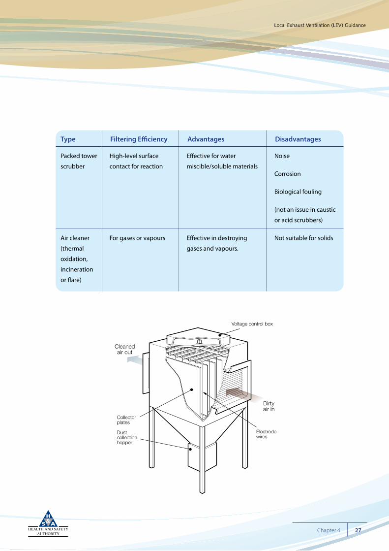
Dirtyair in
Cleanedair out
Electrodewires
Collectorplates
Dust collectionhopper
Voltage control box
Packed tower
scrubber
Air cleaner
(thermal
oxidation,
incineration
or flare)
High-level surface
contact for reaction
For gases or vapours
Effective for water
miscible/soluble materials
Effective in destroying
gases and vapours.
Noise
Corrosion
Biological fouling
(not an issue in caustic
or acid scrubbers)
Not suitable for solids
Type Filtering Efficiency Advantages Disadvantages
Cyan 100%Magenta 76%Yellow 0Black 27%
Local Exhaust Ventilation (LEV) Guidance
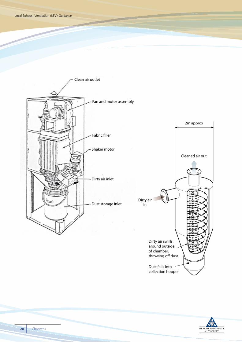
28 Chapter 4
Dirtyair
Dirty air swirls aroundoutside of chamber,throwing off dust
Dust falls into collection hopper
Cleanair
Clean air outlet
Fan and motor assembly
Fabric filler
Shaker motor
Dirty air inlet
Dust storage inlet
2m approx
Cleaned air out
Dirty airin
Dirty air swirls around outside of chamber, throwing off dust
Dust falls into collection hopper
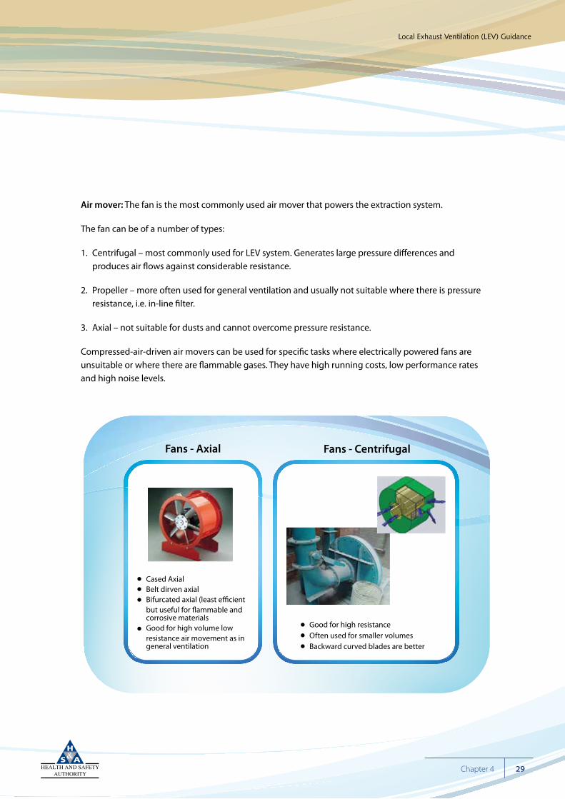
Air mover: The fan is the most commonly used air mover that powers the extraction system.
The fan can be of a number of types:
1. Centrifugal – most commonly used for LEV system. Generates large pressure differences and produces air flows against considerable resistance.
2. Propeller – more often used for general ventilation and usually not suitable where there is pressure resistance, i.e. in-line filter.
3. Axial – not suitable for dusts and cannot overcome pressure resistance.
Compressed-air-driven air movers can be used for specific tasks where electrically powered fans are unsuitable or where there are flammable gases. They have high running costs, low performance rates and high noise levels.
Cyan 100%Magenta 76%Yellow 0Black 27%
Local Exhaust Ventilation (LEV) Guidance
29Chapter 4
Fans - Axial Fans - Centrifugal
Cased AxialBelt dirven axialBifurcated axial (least e�cientbut useful for ammable and corrosive materialsGood for high volume lowresistance air movement as in general ventilation
Good for high resistanceOften used for smaller volumesBackward curved blades are better
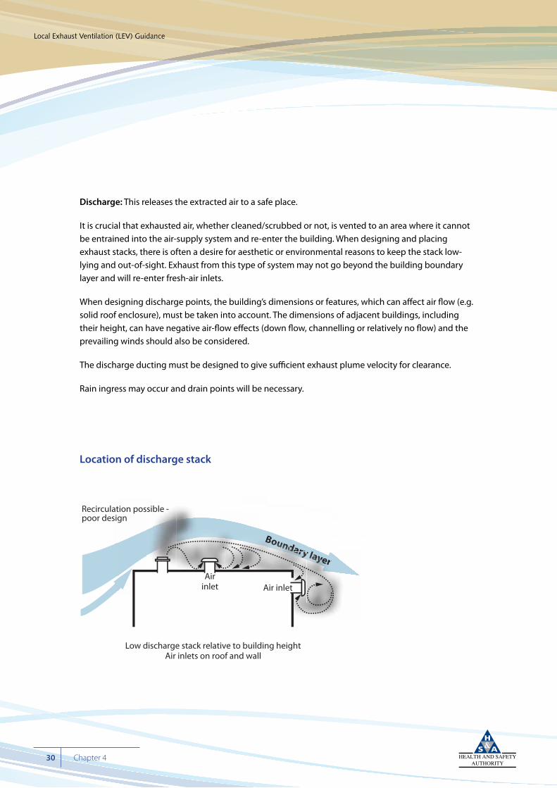
Discharge: This releases the extracted air to a safe place.
It is crucial that exhausted air, whether cleaned/scrubbed or not, is vented to an area where it cannot be entrained into the air-supply system and re-enter the building. When designing and placing exhaust stacks, there is often a desire for aesthetic or environmental reasons to keep the stack low-lying and out-of-sight. Exhaust from this type of system may not go beyond the building boundary layer and will re-enter fresh-air inlets.
When designing discharge points, the building’s dimensions or features, which can affect air flow (e.g. solid roof enclosure), must be taken into account. The dimensions of adjacent buildings, including their height, can have negative air-flow effects (down flow, channelling or relatively no flow) and the prevailing winds should also be considered.
The discharge ducting must be designed to give sufficient exhaust plume velocity for clearance.
Rain ingress may occur and drain points will be necessary.
Location of discharge stack
Cyan 100%Magenta 76%Yellow 0Black 27%
Local Exhaust Ventilation (LEV) Guidance
30 Chapter 4
Boundary layeryydadadaadadaddadadddddddd ryyry l
daddadadadaaadddadaryyryrryyyereer
yyyyyyyyyyyyy lllllllllllayayayayayayayayaayayayayayayaaaaaaaaaaaaaryryryryryryryyyyyyyyyyy
BBooBoBoBoBoBoBoBooooooounununuununununununununununununuununununuu ddddddddddddddddddddddBBBBBBBBB
Air inletAir
inlet
Recirculation possible -poor design
Low discharge stack relative to building heightAir inlets on roof and wall
Below are some of the commonly held misconceptions regarding LEV:
• Air being drawn into a ducting system is drawn from many directions unless directed or controlled by a hood. As a consequence, as the source moves from the hood, the air flow towards the hood diminishes rapidly. As a rule of thumb, for round ducting, at one diameter distance from the opening, the air flow will be reduced to approximately 10% of the total volume. Therefore (1) good design to maximise performance; and (2) proper positioning of flexible systems are crucial.
• A fume cupboard, to take an example, operates at a sash-plane face velocity of 0.5 m/s. This flow can easily be overcome by counter-currents and uncontrolled draughts. This can be easily demonstrated with smoke testing. In order to maintain its effectiveness, it is important that the hood be used correctly. For example, work should be kept well into the hood, the sash should be open to the minimum to allow work to proceed, and the external environment should be controlled so that draughts or sudden changes in air supply do not challenge the fume cupboard performance. This holds true for all LEV: the hood/booth should be used as designed and the external environment should be controlled to avoid challenging the flow rate.
• Remember air flow is seldom uniform or laminar. Surfaces cause drag which can lead to low/no flow or eddies.
• The operator’s body, or other solid objects, if placed in the flow path, will obstruct flow and generate dead areas.
See the illustrations below.
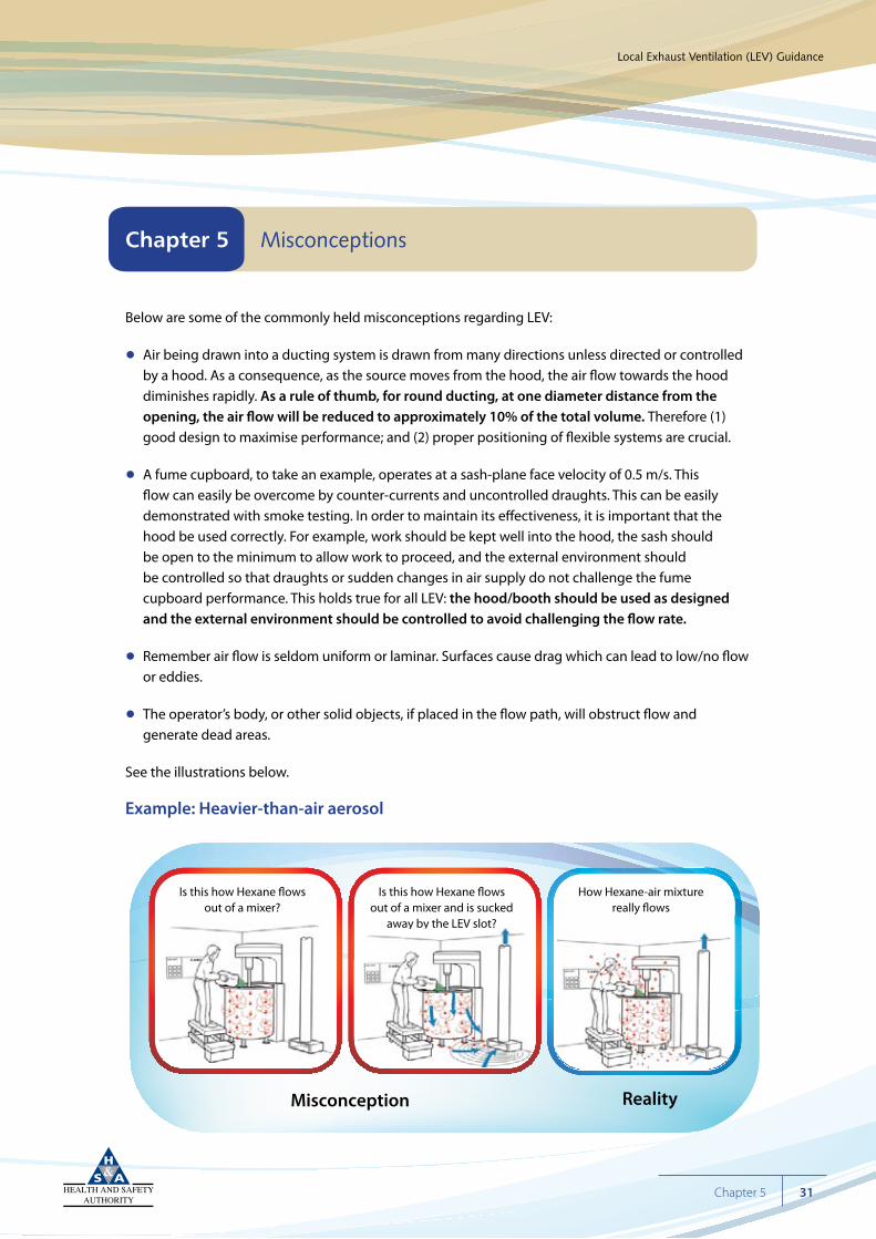
Example: Heavier-than-air aerosol
Cyan 100%Magenta 76%Yellow 0Black 27%
Local Exhaust Ventilation (LEV) Guidance
31Chapter 5
Chapter 5 Misconceptions
Is this how Hexane �owsout of a mixer?
Is this how Hexane �owsout of a mixer and is sucked
away by the LEV slot?
How Hexane-air mixturereally �ows
RealityMisconception
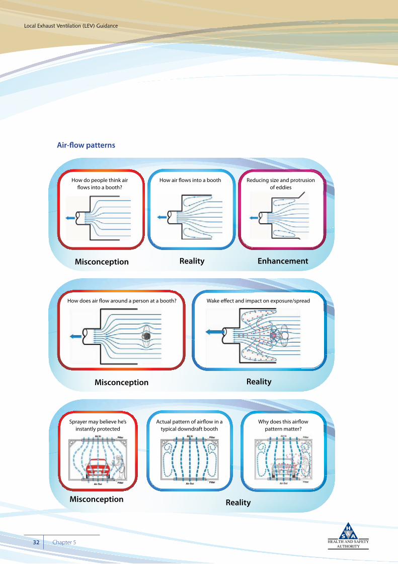
Air-flow patterns
Cyan 100%Magenta 76%Yellow 0Black 27%
Local Exhaust Ventilation (LEV) Guidance
32 Chapter 5
How do people think air�ows into a booth?
How air �ows into a booth Reducing size and protrusionof eddies
Reality EnhancementMisconception
How does air �ow around a person at a booth? Wake e�ect and impact on exposure/spread
RealityMisconception
Sprayer may believe he’sinstantly protected
Actual pattern of air�ow in atypical downdraft booth
Why does this air�owpattern matter?
RealityMisconception
Cyan 100%Magenta 76%Yellow 0Black 27%
Local Exhaust Ventilation (LEV) Guidance
33Chapter 5
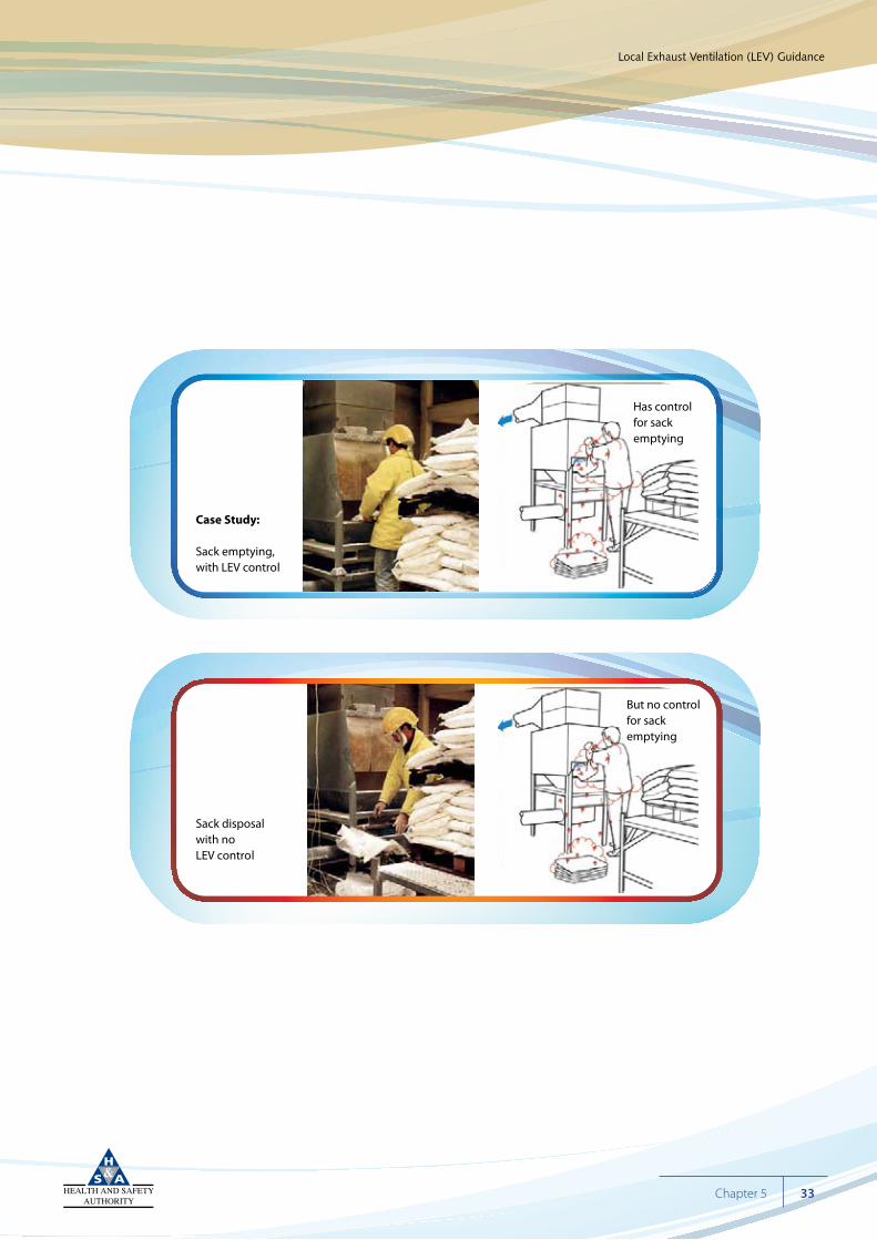
Case Study:
Sack emptying, with LEV control
Has controlfor sackemptying
Sack disposalwith noLEV control
But no controlfor sack emptying
Cyan 100%Magenta 76%Yellow 0Black 27%
Local Exhaust Ventilation (LEV) Guidance
34 Chapter 5
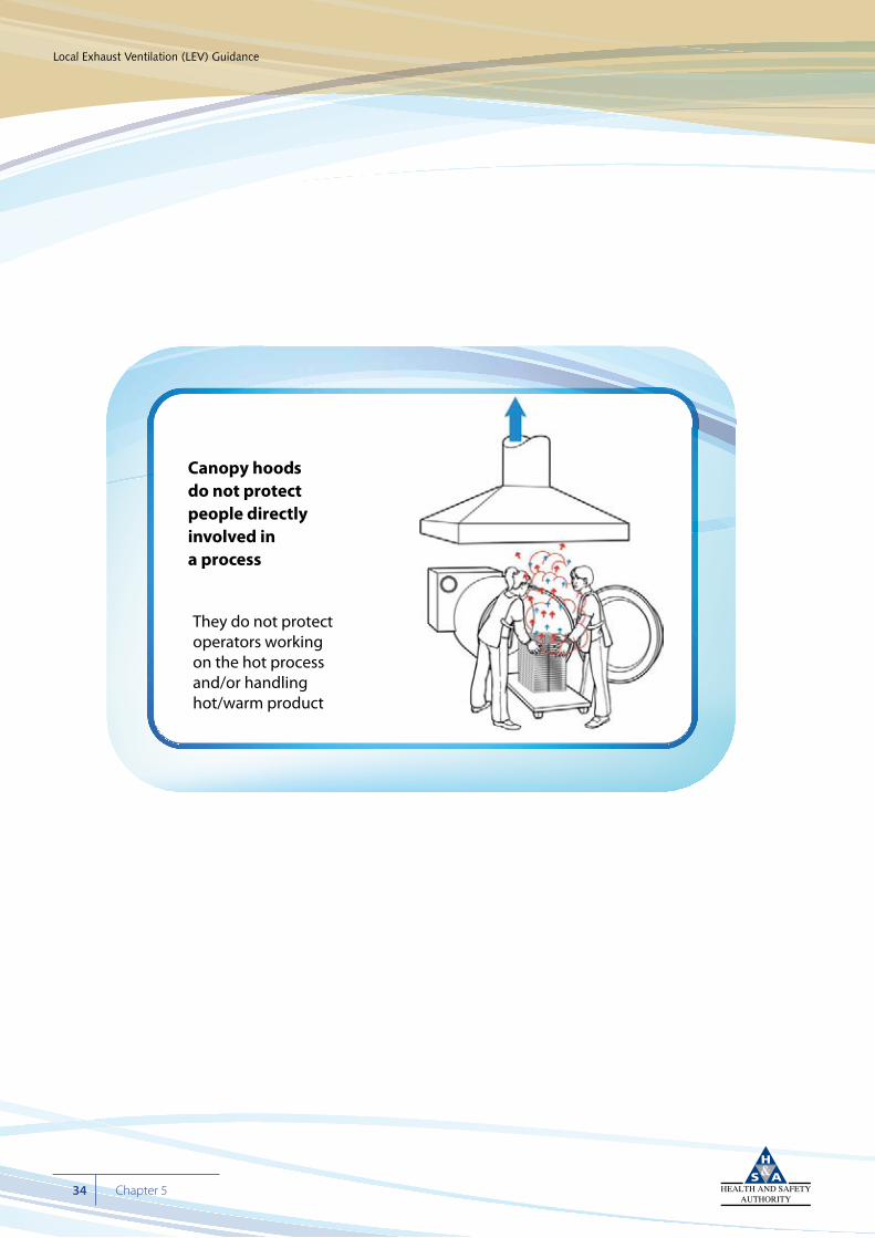
Canopy hoodsdo not protectpeople directlyinvolved in a process
They do not protect operators workingon the hot processand/or handlinghot/warm product
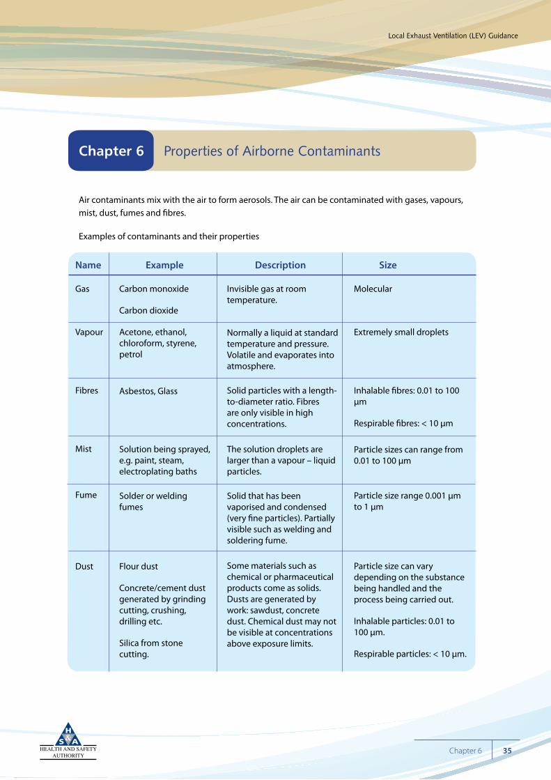
Air contaminants mix with the air to form aerosols. The air can be contaminated with gases, vapours, mist, dust, fumes and fibres.
Examples of contaminants and their properties
Cyan 100%Magenta 76%Yellow 0Black 27%
Local Exhaust Ventilation (LEV) Guidance
35Chapter 6
Chapter 6 Properties of Airborne Contaminants
Gas
Vapour
Fibres
Mist
Fume
Dust
Carbon monoxide
Carbon dioxide
Acetone, ethanol, chloroform, styrene, petrol
Asbestos, Glass
Solution being sprayed, e.g. paint, steam, electroplating baths
Solder or welding fumes
Flour dust
Concrete/cement dust generated by grinding cutting, crushing, drilling etc.
Silica from stone cutting.
Invisible gas at room temperature.
Normally a liquid at standard temperature and pressure. Volatile and evaporates into atmosphere.
Solid particles with a length-to-diameter ratio. Fibres are only visible in high concentrations.
The solution droplets are larger than a vapour – liquid particles.
Solid that has been vaporised and condensed (very fine particles). Partially visible such as welding and soldering fume.
Some materials such as chemical or pharmaceutical products come as solids. Dusts are generated by work: sawdust, concrete dust. Chemical dust may not be visible at concentrations above exposure limits.
Molecular
Extremely small droplets
Inhalable fibres: 0.01 to 100 µm
Respirable fibres: < 10 µm
Particle sizes can range from 0.01 to 100 µm
Particle size range 0.001 µm to 1 µm
Particle size can vary depending on the substance being handled and the process being carried out.
Inhalable particles: 0.01 to 100 µm.
Respirable particles: < 10 µm.
Name Example Description Size
The properties of airborne contaminants can be divided into three general groups: chemical, physical and biological. The properties of the contaminants will influence the design, manufacture, performance, use and maintenance of the system.
Flammable contaminants:
Where flammable or combustible materials are being extracted, given the right conditions there is always a risk of fire or explosion. A fire or explosion within ducting can propagate the length of the ducting and quickly spread fire to other areas, depending on the amount of ducting and whether the necessary conditions for fire are present.
For a fire to occur there must be: (1) a fuel, a combustible or flammable material; and (2) oxygen as supplied by air in the ducting. These two ingredients must be mixed in a sufficient ratio range (flammable/combustion/explosion lower or upper limits – LEL or UEL) to initiate and sustain a fire. Fuel can vary from flammable solvent vapour to grain or wood dust. To initiate a fire a source of ignition is necessary. A static discharge or a spark or friction heat from moving parts may be sufficient to initiate a fire.
To prevent a fire (break the fire triangle) there should be sufficient air flow through the ducting to prevent an accumulation of fuel, such as wood dust, settling out within the ducting and also avoid the generation of a fuel air mixture within a flammable range. Bonding and earthing may be necessary to prevent static build-up and regular maintenance will prevent friction heat and sparking, thereby eliminating such sources of ignition.
Corrosives:
Corrosive substances may corrode the various components of the LEV system and render it ineffective by short-circuiting the air flow, damaging the filtering process or impairing the fan rotors. Corrosion damage will cause loss of control; reduction in performance and may cause exposure to employees. This can become a less obvious concern where processes and materials change and the LEV is now being used not as originally designed.
Cyan 100%Magenta 76%Yellow 0Black 27%
Local Exhaust Ventilation (LEV) Guidance
36 Chapter 6
Toxic or harmful:
The primary purpose of having LEV is to prevent employee exposure to hazardous chemical agents. The contaminant may also be harmful to the environment and therefore filtering or scrubbing the discharge may be crucial.
Physical properties:
Where vapours are heavier than air, it is important that the capturing containing devices are so placed that they are effective in exhausting the contaminant. The contaminant may receive kinetic energy because of the process. For example, the evaporation rate of volatile solvents will increase with temperature. Grinding, cutting, crushing, drilling, milling, dropping materials through a hopper, etc. all provide energy which may propel the contaminant, generate extensive aerosols and overwhelm LEV systems.
Particle size is important in that in general smaller particles can disperse further and remain airborne longer before settling on work surfaces. Also the particle size determines whether or not a particle can be inhaled. Particles with an aerodynamic diameter range of 0.01µm up to 100µm can be inhaled. Within this range, respirable particles <10 µm can be inhaled deep into the alveolar region of the lungs.
Biological:
A biological safety cabinet is the common type of LEV for biological contaminants. See the Health and Safety Authority’s Guidelines for the Biological Agents Regulations for detailed guidance on biological safety cabinets.
Cyan 100%Magenta 76%Yellow 0Black 27%
Local Exhaust Ventilation (LEV) Guidance
37Chapter 6
The ability of a local exhaust ventilation system to reduce exposure to air contaminants is determined primarily by the effectiveness of the hood(s). Ensure they are provided with sufficient air flow to contain and capture contaminants; also, verify the ability of the fan and ducting to extract sufficient air from each hood. Flow rates can vary depending on the work being done. For example, a glove box or fully enclosed system needs sufficient flow to maintain it under a negative pressure with a relatively small flow rate within it. However, a relatively higher flow rate is required when the hood is capturing fugitive contaminants, especially those that may be propelled by the mechanical energy of grinding, cutting, etc.
Once the contaminant is captured, the flow rate within the ducting must be sufficient to transport the contaminant to the filtering system and on to the exhaust. In a system with many duct branches to individual hoods, there may be a header system. Whether simple or complex, the ducting structure and dimensions will influence the air-flow rate. The flow rate must be sufficient to dilute flammable or combustible contaminants and not allow an accumulation within the ducting that could lead to a fire.
The design, work or process needs or employee use can influence flow rates. Over time, wear and tear can cause the flow rates to reduce. Regular monitoring is crucial.
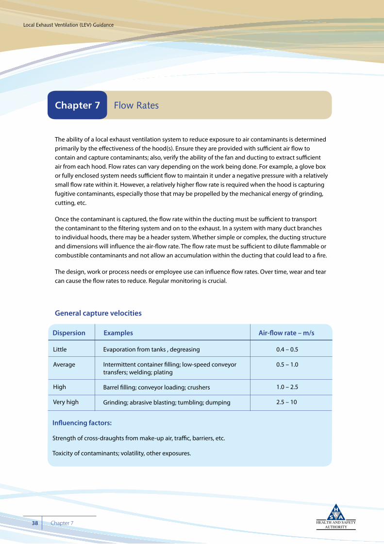
General capture velocities
Cyan 100%Magenta 76%Yellow 0Black 27%
Local Exhaust Ventilation (LEV) Guidance
38 Chapter 7
Chapter 7 Flow Rates
Little
Average
High
Very high
Evaporation from tanks , degreasing
Intermittent container filling; low-speed conveyor transfers; welding; plating
Barrel filling; conveyor loading; crushers
Grinding; abrasive blasting; tumbling; dumping
0.4 – 0.5
0.5 – 1.0
1.0 – 2.5
2.5 – 10
Dispersion Examples Air-flow rate – m/s
Influencing factors:
Strength of cross-draughts from make-up air, traffic, barriers, etc.
Toxicity of contaminants; volatility, other exposures.
General duct velocities
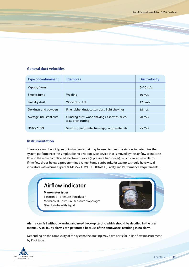
Instrumentation
There are a number of types of instruments that may be used to measure air flow to determine the system performance; the simplest being a ribbon-type device that is moved by the air flow to indicate flow to the more complicated electronic device (a pressure transducer), which can activate alarms if the flow drops below a predetermined range. Fume cupboards, for example, should have visual indicators with alarms as per EN 14175-2 FUME CUPBOARDS, Safety and Performance Requirements.
Alarms can fail without warning and need back-up testing which should be detailed in the user manual. Also, faulty alarms can get muted because of the annoyance, resulting in no alarm.
Depending on the complexity of the system, the ducting may have ports for in-line flow measurement by Pitot tube.
Cyan 100%Magenta 76%Yellow 0Black 27%
Local Exhaust Ventilation (LEV) Guidance
39Chapter 7
Air�ow indicatorManometer types:Electronic – pressure transducerMechanical – pressure-sensitive diaphragmGlass U-tube with liquid
Vapour, Gases
Smoke, fume
Fine dry dust
Dry dusts and powders
Average industrial dust
Heavy dusts
Welding
Wood dust, lint
Fine rubber dust, cotton dust, light shavings
Grinding dust, wood shavings, asbestos, silica, clay, brick cutting
Sawdust, lead, metal turnings, damp materials
5–10 m/s
10 m/s
12.5m/s
15 m/s
20 m/s
25 m/s
Type of contaminant Examples Duct velocity
When the employer has completed a risk assessment, evaluated the risks and determined the potential hazards from chemical agents, control methods need to be considered. As well as health hazards, there may be flammability, reactivity and physical (excessive heat) hazards.
In installing controls, the employer, having started at the top of the hierarchy, has decided to install a local exhaust system to attain control.
The LEV system must be fit for purpose. For example, where the process entails grinding, it is likely that dust will be propelled from the source and the system needs to be designed to contain or capture the fugitive dust. Before designing or installing an LEV system, a good understanding of contaminants and the process demands are necessary. The following will also need to be considered: Will the system be required to cope with changing materials and processes? Does it need to be flexible/adaptable, simple or complex (this depends on the processes and the potential exposure points the risk assessment has highlighted).
Are you an end user under REACH? Have you informed your supplier of your intended uses and has he advised you with an up-to date Safety Data Sheet (SDS)?
There may be a standard off-the shelf system that would be suitable. It may be necessary to get the advice of an expert such as an occupational hygienist or a ventilation engineer.
Firstly, a specification should be drawn up for the employer’s review. The specification should consider the work processes, the employees involved, the potential fugitive dusts/fumes/gases and the likely sources or points of exposure. It is critical that all exposure points are identified so that the specification is accurate and expensive retro-fitting is avoided. The thoroughness of the risk assessment in initially identifying the areas where control is needed is fundamental to ensuring the installation of an effective system. Regardless of whether the installation is likely to be simple or complex, the employer, consulting with his/her employees who know his process, should work closely with any consultant to achieve an effective design.
Cyan 100%Magenta 76%Yellow 0Black 27%
Local Exhaust Ventilation (LEV) Guidance
40 Chapter 8
Chapter 8 How to Select Local Exhaust Ventilation (LEV)
In designing the system, each element will need to be considered while, at the same time, each element should integrate into the overall system. Also, the system cannot be designed in isolation. What other ventilation systems are in place? Is there a controlled supply or supply/exhaust ventilation? Is the area naturally ventilated through doors and windows? Existing conditions, including lack of control, consistent air movement or draughts will seriously affect the performance of the LEV.
The sources and type of contaminant will dictate the type of inlet/enclosure/hood required. For example, the contaminant can be:
1. buoyant, such as a hot fume
2. injected or propelled into moving air such as spray from paint-spray gun
3. dispersed into the workplace air by general ventilation/draughts
4. directional, e.g. in grinding/cutting.
The ducting must be correctly sized to conduct the air and transport the contaminant to the filter and the discharge point. If the ducting is multi-point, will the system be designed to operate all or a percentage of exhaust points at any one time? How will this be controlled?
Cyan 100%Magenta 76%Yellow 0Black 27%
Local Exhaust Ventilation (LEV) Guidance
41Chapter 8
There are many choices of air cleaning and filtering systems as outlined above, depending on the process, the contaminants and the employee requirements.
The air mover has to maintain the air flow in the anticipated conditions as highlighted in the risk assessment.
The discharge will have to take account of the requirements for the specific exhaust plume and the unique topography of the area to ensure re-entrainment of exhaust air into supply air does not occur.
The specification should also ensure the LEV is easy and safe to check out, maintain and clean. Details on how the supplier will demonstrate the effectiveness of the system for the specific needs of the employer’s processes must be provided (commissioning process).
Performance indicator instruments, such as manometers on hood ducts, should be installed so that the employer and employees can determine and record if necessary the performance rate of the system.
The specification should indicate the training to be given to staff such as supervisors, users and maintenance personnel at installation.
The employer should receive a user manual from the installer/manufacturer for future reference and for training purposes (see next chapter on installation and maintenance).
Employees must be consulted and involved in drawing up the specification to make sure the system to be installed is effective and practical for use.
The employer is responsible for making sure the supplier is competent to install the LEV system. Compare their plans with the specification. Check out their experience and competence to carry out the work.
Cyan 100%Magenta 76%Yellow 0Black 27%
Local Exhaust Ventilation (LEV) Guidance
42 Chapter 8
OVERVIEW
New LEVWhen installing LEV, use a reputable supplier, with experience of the type of control that is needed who can demonstrate that their system will adequately control potential contaminants.
Installation and commissioningThe LEV supplier should prepare a user manual describing what the LEV is designed to control, and how it achieves control. It should also contain the following:
• The LEV system description, with drawings and diagrams
• The initial performance from commissioning
• Checks, maintenance and parts replacement schedules
• Signs of wear and control failure to monitor
• Description of how operators should use the LEV so it works effectively
• A list of replaceable parts.
Once the design specifications have been agreed, the installation and commissioning phase can commence. The complexity of the system will have a major impact on this phase. The employer needs to consider how the work will impinge on his enterprise.
The first step is the project management, construction and installation phase. Will fabrication be carried out on site? Is this a large installation affecting major parts of the premises? For construction site requirements, see the HSA website (www.hsa.ie) under ‘Construction’. There are specific requirements laid down in the Safety, Health and Welfare at Work (Construction) Regulations, 2006 S.I. 504 of 2006 as amended. Make sure the system is installed as agreed in initial specification.
Cyan 100%Magenta 76%Yellow 0Black 27%
Local Exhaust Ventilation (LEV) Guidance
43Chapter 9
Chapter 9 Installation and Maintenance of LEV
Once installed, the commissioning phase begins. Commissioning is proving the LEV system is (1) capable of providing adequate control; and (2) working to design. The commissioning activity must consider the work practices as well as the LEV ‘hardware’ if it is to be a true measure of performance.
Components of the commissioning process would be: physically checking the integrity of the system:
• Is it fabricated using the proper materials (fan, ducting)?
• Has it been assembled correctly (e.g. fan rotation) and according to agreed drawings and plans?
• Is the system intact and not leaking or undone at any point?
Following on from the physical checks, the air-flow rates at each hood/inlet must be checked by the installer and, where the system is multi-branched, the air flows must be balanced using in-line blast gates or sliding dampers.
At this point, the effectiveness of control should be verified. All qualitative and quantitative checks should be completed to verify the system works to design criteria. Make sure operators understand the system and are using it as designed.
Once commissioned, the complete data set, from design to commissioning, should be collected and issued to the employer. The data should be transferred to the employer/user in a user manual.
User manual
A user manual should be supplied as part of the design, installation and commissioning process. The employer needs the user manual:
• To assist in understanding the technicalities of the system.
• To have available guidance and instructions for maintenance, examination of system and training of employees in the correct use.
Cyan 100%Magenta 76%Yellow 0Black 27%
Local Exhaust Ventilation (LEV) Guidance
44 Chapter 9
User manual contents:
> Initial specification
> Design criteria
> Initial performance measurements
> Purpose and description of the LEV system, including drawings and diagrams
> Instructions on how to use the LEV
> Performance information collected during commissioning
> Daily, weekly and longer-term checks
> Common early signs of deterioration in performance or wear and tear
> Details of what checks should be carried out at each annual examination and test of the system
Checking and maintaining existing LEV
The system needs to be thoroughly examined regularly to demonstrate it is performing to design. It is recommended that the system be checked at least every 14 months, or more frequently if the manufacturer recommends it. Also, simple routine checks can be carried out when the system is in use.
As well as checking exhaust performance rates, checks and maintenance of the complete system are essential, especially moving parts that wear, e.g. fan motors/drives, gear wheels, fan belts, fan bearings, filter shakers; hoods, ductwork flanges and seals that can be corroded or damaged also need to be checked, along with any parts that may deteriorate with use, e.g. filters, flexible ducting, and items that need regular attention, e.g. dust collectors, cyclones, scrubbers. System parts that are outdoors may, in time, become corroded and leak.
A record (log book) should be kept which indicates the initial design criteria and required monitoring checks, actual records and dates of performance monitoring, maintenance, parts replacement or any modification to the system.
Cyan 100%Magenta 76%Yellow 0Black 27%
Local Exhaust Ventilation (LEV) Guidance
45Chapter 9
If no records are available (e.g. a commissioning report), a competent ventilation engineer or occupational hygienist can assist to determine the effectiveness of the system and what measures are needed for adequate control.
Maintenance checks may increase the potential for exposure to contaminants (e.g. dirty filters) and entry into confined spaces. Maintenance measures should be risk assessed before being carried out.
Maintenance records should be kept from year to year to demonstrate ongoing effectiveness of the system and to assist in determining any deterioration by way of comparison with previous results. Maintenance must be carried out by a person who is competent in the operation of the LEV system.
Any deficiencies found during system monitoring should be rectified to ensure the LEV is effective when in use, and these interventions/modifications should be included in LEV records.
Where maintenance work involves any entry into a confined space, consult the HSA Code of Practice for Working in Confined Spaces (see www.hsa.ie, under publications).
Cyan 100%Magenta 76%Yellow 0Black 27%
Local Exhaust Ventilation (LEV) Guidance
46 Chapter 9
The employee using the LEV system should receive sufficient training so that they use the system effectively. Training should be specific and deal with the actual system in place. The employee should:
• understand the elements of the system and how they work;
• understand how to use the system effectively (for example, how to correctly place an extraction hood);
• appreciate the limitations of the system and how they might render it ineffective. Often, employers/employees overestimate the robustness of the LEV system and do not appreciate that the system can easily be rendered ineffective by: environmental changes outside the design specifications (for example, changes in general ventilation, draughts); misuse or misplacement of equipment (for example, misuse of a fume cupboard or failure to maintain and monitor performance);
Cyan 100%Magenta 76%Yellow 0Black 27%
Local Exhaust Ventilation (LEV) Guidance
47Chapter 10
Chapter 10 Information and Training for Employees
• know how to check that the LEV is working (reading flow indicators, pressure differential meters);
• know what actions to take in the event of a system failure.
To carry out routine checks, employees need to know:
1. The separate parts of the LEV and their functions.
2. How to recognise a damaged part from a visual inspection.
3. How to read flow-indicating instruments.
4. How to check the system is operating correctly and that it is effectively controlling emissions.
Maintenance staff will need the above training and relevant specific training relating to the maintenance of the system and hazards arising, such as potential exposure to contaminants and the hazards of possible entry into a confined space. The risk assessment should highlight possible risks that need action.
The employer should keep training records for each concerned employee.
Changes to the work process and LEV mean that staff may need retraining.
Cyan 100%Magenta 76%Yellow 0Black 27%
Local Exhaust Ventilation (LEV) Guidance
48 Chapter 10
Keeping records as outlined below is crucial to demonstrate that the system is effective, has been performing as designed and continues to do so.
On installation, the employer should receive a user manual from the installer/manufacturer which should be kept on record for future reference and training.
User manual contents:
> Initial specification
> Design criteria
> Initial performance measurements
> Purpose and description of the LEV system, including drawings and diagrams
> Instructions on how to use the LEV
> Performance information collected during commissioning
> Daily, weekly and longer-term checks
> Common early signs of deterioration in performance or wear and tear
> Details of what checks should be carried out at each annual examination and test of the system
If no records are available (e.g. a commissioning report), a competent ventilation engineer or occupational hygienist can assist to determine the effectiveness of the system and what measures are needed for adequate control. Maintenance records should be kept from year to year to demonstrate ongoing effectiveness of the system and to assist in determining any deterioration by way of comparison with previous results.
Any deficiencies found during system monitoring should be rectified to ensure the LEV is effective when in use and these interventions/modifications should be included in LEV records.
Where maintenance work involves any entry into a confined space, records of checks made prior to entry should be made.
Where the employer uses anemometers or similar equipment to monitor ventilation performance, the calibration certificates, certificates of conformance etc. should be kept on file.
Cyan 100%Magenta 76%Yellow 0Black 27%
Local Exhaust Ventilation (LEV) Guidance
49Chapter 11
Chapter 11 Keeping Records
This section gives guidance on the key points regarding examination and performance monitoring. The examiner/auditor/engineer/technician/employee carrying out the testing needs to be competent and have a knowledge of LEV monitoring beyond the fundamental points outlined below.
The examining and monitoring of LEV is different from the normal use and should be risk assessed appropriately before commencing the examination. It will, for example, be necessary to lock out or de-energise systems such as fan motors during examination and there may be confined space hazards where filter housings must be entered. The risk of contact with contaminant may also be a factor.
The LEV should be monitored by the user on an ongoing or routine basis when in use. There are many good reasons for regular monitoring. For example:-
• It is vital to record the initial performance of the ventilation system when it is being commissioned as this data will be the base line for future comparisons for performance measurement.
• Regular monitoring demonstrates and proves ongoing performance is as required. Over time, for a number of reasons (wear and tear from use, ageing, corrosion by the elements, user-misuse, etc.), elements of the system can deteriorate, leading to less than design performance.
• Where a system has a number of hoods or branching sections, balancing may be necessary to distribute the exhaust rate correctly between hoods. Regular monitoring will detect adjustment in blast gates and related changes in flow rates and balancing.
• In the event of the LEV failing, regular monitoring will assist in speedy diagnosis of a failure such as a broken connection or blockage.
• In the event that the system needs modification, such as adding or removing a branch, the historical monitoring data will aid the management of change to the LEV.
These checks should be logged or recorded appropriately. Every LEV system should be thoroughly examined regularly. It is recommended this is done at least every 14 months.
Cyan 100%Magenta 76%Yellow 0Black 27%
Local Exhaust Ventilation (LEV) Guidance
50 Chapter 12
Chapter 12 Examining & Monitoring Performance
To have an effective performance-monitoring programme following commissioning, the employer should:
1. carry out routine monitoring while in use;
1. organise thorough monitoring and performance testing at least every 14 months;
2. document inspections and performance testing;
3. prioritise remedial or overhauling maintenance where necessary.
Routine monitoring
Routine checks keep the LEV system running properly. Ideally, the frequency of routine checks and their description should be set out and recorded in a log book. An employee should be trained to make routine checks. Failures detected should be reported and then acted upon.
Routine checks can include:
• checking manometer readings are in the correct range;
• checking static pressure readings;
• checking ducts and hoods not damaged;
• checking there is no visible leakage;
• checking filter system.
Annual performance testing
An annual examination and performance monitoring should be a detailed systematic examination to ensure the LEV continues, as intended by design, to achieve adequate control. The testing and examination may be carried out by an employee who is competent in the operation of the LEV system, or an outside contractor, such as a consultant occupational hygienist or ventilation engineer.
Cyan 100%Magenta 76%Yellow 0Black 27%
Local Exhaust Ventilation (LEV) Guidance
51Chapter 12
There are a variety of instruments such as different types of anemometers, varieties of Pitot tubes and various manometers used to measure air velocity. There is also the consideration of good technique when using a measuring instrument. The manufacturer of the LEV may give instructions on monitoring. Because of these complexities, it is important that the examiner/auditor, whether in-house or an external contractor, can demonstrate their competence in completing the performance monitoring.
Before carrying out any testing, the work to be done should be assessed for risks and appropriate action taken. The employee or contractor needs to know if there are any material residues within the system that could be hazardous. Are there physical hazards such as working from heights, electrical hazards, moving machinery, manual handling specific to the LEV testing?
Examining filters and scrubbers may increase the risk of chemical contact and the hazards associated with entering a confined space.
Before carrying out any measurements, the examiner should have available to him or her:
• a copy of the commissioning report;
• the results of the previous annual performance testing if appropriate;
• the log of routine testing.
He/she should be able to confirm that there have been no modifications to the system since the last testing. If these reports are not available, then this test has to become the base-line test. His/her report should recommend documented routine testing as outlined above.
Physical examination:
Before any flow measurement, the examiner should carry out a thorough physical examination of the system and all its components, looking for damage, corrosion or wear and tear.
• Check around the hood/enclosure for soiling and deposits which would indicate that the contaminants are not being extracted properly; the flow-rate may not be effective (filtering devices may be blocked, for example). There could be a number of causes – see questions below – for an accumulation of contaminants, including poor or no testing/servicing.
Cyan 100%Magenta 76%Yellow 0Black 27%
Local Exhaust Ventilation (LEV) Guidance
52 Chapter 12
• Are connections and flanges well sealed? Is there staining to suggest outward leakage?
• Are inspection ports in place?
• Is the system intact? Check all sides of ducting for damage/corrosion/holes.
• Are hoods/enclosures in good condition and working as designed (doors sealing, baffles and fume-cupboard sashes movable, etc.)?
• Are manometers easily read and indicating correctly?
• Are orifice/blast gates in place and secure?
• Is the flow through hoods or booths impeded by storage of materials within them? A hood is not a storage cabinet and it is important that only items being used for work are placed with in it. Over- filling will lead to undesirable turbulence and dead spots.
• Are filtering systems to be overhauled? Are they intact? This may involve opening the system and changing filters, bags, etc., leading to potential exposure to contaminant. Are wet scrubbers in use? Again these will need specific monitoring to determine the scrubbing of exhaust air is effective. Any filter/scrubber system may involve access to confined spaces for both ducting and filter housing. Confined spaces may have a lack of oxygen necessary for breathing. Some filters have shakers or air pulses to clean filters. Do these systems perform to design?
• Is the air mover (fan/motor and equipment) intact? Are drive belts in place and not damaged or frayed?
Testing performance
One velocity measurement is seldom enough to determine the average velocity, as the air flow at the hood face or within the duct is seldom uniform. It is important to measure the air velocities at several locations and then calculate the average value. For the measured air flow to be a good estimate of the true value, measurements must be taken correctly, in the right locations and there must be enough measurements to include most of the variability. Ideally, measurement should be carried out 10 duct diameters from any obstruction.
Cyan 100%Magenta 76%Yellow 0Black 27%
Local Exhaust Ventilation (LEV) Guidance
53Chapter 12
Different devices need different approaches:
• Full enclosure, such as glove boxes: a manometer to monitor the static pressure differential between the enclosure and the external environment is necessary.
• Partial enclosures such as fume cupboards, booths: face velocity can be monitored using various types of anemometers.
• Capturing or receiving hoods: it may be possible to measure the face velocities with an anemometer or complete in-duct measurements using a Pitot tube manometer system.
• For plenums, ducts: in-duct measurement is necessary.
• Smoke testing can demonstrate, qualitatively, the performance for booths, fume cupboards, receiving or capturing hoods. The test can highlight eddies and turbulence which can significantly affect performance.
• A Tyndall lamp can also be used to demonstrate containment and capture of dusts and fumes.
The use of smoke testing and the Tyndall lamp can be very effective in visualising flow direction, velocity contours, eddy current, etc.
Monitoring for air flowing through a duct is not uniform across the duct at any given cross-section. Frictional drag along the ducts causes the air near the surface of the duct to flow slower than the air in the centre of the duct. Duct fittings and obstacles – such as elbows, branches, contractions, dampers – cause significant variation in the velocity profile. Under ideal conditions the velocity will increase with distance from the inner surface to the centre of the duct, so taking a centre-point reading alone will over-estimate the flow rate.
To accurately estimate the average velocity, measurements must be taken at representative points across the entire cross-section of the duct. This can be done by inserting a Pitot tube into a hole in the duct and taking readings at different depths along the diameter or traverse. For sampling locations to be representative, every area of the duct should have an equal chance of being sampled. For this reason, the traverse points are not evenly spaced, but instead are chosen so that each point represents close to the same amount of air flow.
Cyan 100%Magenta 76%Yellow 0Black 27%
Local Exhaust Ventilation (LEV) Guidance
54 Chapter 12
Cyan 100%Magenta 76%Yellow 0Black 27%
Local Exhaust Ventilation (LEV) Guidance
55Chapter 12
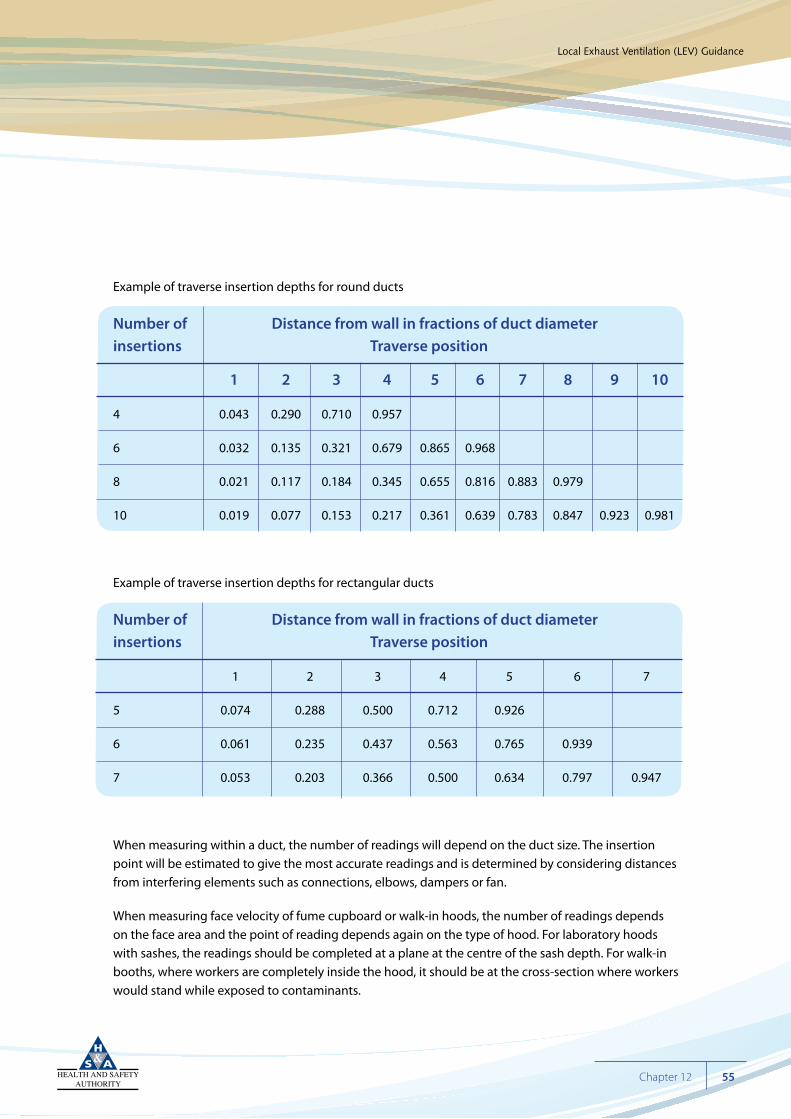
Example of traverse insertion depths for round ducts
Number of Distance from wall in fractions of duct diameterinsertions Traverse position
1 2 3 4 5 6 7 8 9 10
4 0.043 0.290 0.710 0.957
6 0.032 0.135 0.321 0.679 0.865 0.968
8 0.021 0.117 0.184 0.345 0.655 0.816 0.883 0.979
10 0.019 0.077 0.153 0.217 0.361 0.639 0.783 0.847 0.923 0.981
Example of traverse insertion depths for rectangular ducts
Number of Distance from wall in fractions of duct diameterinsertions Traverse position
1 2 3 4 5 6 7
5 0.074 0.288 0.500 0.712 0.926
6 0.061 0.235 0.437 0.563 0.765 0.939
7 0.053 0.203 0.366 0.500 0.634 0.797 0.947
When measuring within a duct, the number of readings will depend on the duct size. The insertion point will be estimated to give the most accurate readings and is determined by considering distances from interfering elements such as connections, elbows, dampers or fan.
When measuring face velocity of fume cupboard or walk-in hoods, the number of readings depends on the face area and the point of reading depends again on the type of hood. For laboratory hoods with sashes, the readings should be completed at a plane at the centre of the sash depth. For walk-in booths, where workers are completely inside the hood, it should be at the cross-section where workers would stand while exposed to contaminants.
Also consult EN 14175-1 to 7, FUME CUPBOARD, standards relating to hoods (See standards section below).
Once the system has been set up, balanced and a base line established to demonstrate it can deliver design air flows, the static pressures taken with the base-line measurements can be used to determine the ongoing actual system performance, if the system has in-line static pressure gauges (manometers). The manometers can be easily read and logged as part of the routine testing and give a quick indication of the air-flow performance level. In general, if the static-pressure readings are 20% above or below the base-line limits, then remedial action needs to be taken.
When measuring performance, there are a number of essential points:
• Monitoring should be carried out where conditions reflect the true working environment.
• Ensure that environmental conditions in the workplace (doors, windows, draughts, movement, etc.) are not adversely affecting flow rates.
• The measurement points should be well chosen to ensure an accurate reading.
• The employee or consultant carrying out the monitoring should have an understanding of the ventilation system, the monitoring techniques, the potential for errors and how to interpret results.
By proper monitoring and ongoing checking, the employer can be assured that the LEV system is operating as designed, and, with regular non-onerous checking (static-pressure readings), any deterioration in performance will be quickly detected, should a fault arise.
For more comprehensive data on performance-measuring techniques, consult the publications in the reference section of these guidelines.
Cyan 100%Magenta 76%Yellow 0Black 27%
Local Exhaust Ventilation (LEV) Guidance
56 Chapter 12
Cyan 100%Magenta 76%Yellow 0Black 27%
Local Exhaust Ventilation (LEV) Guidance
57Chapter 13
(Not an exhaustive list)
Safety, Health and Welfare at Work Act 2005
In essence, the Act requires the employer to manage health and safety in the workplace, and to prevent and reduce risks to health and safety, through the provision of safe systems of work by completing a risk assessment and putting controls in place. He/she is also required to consult with employees or their safety representative, to provide adequate instruction, training, supervision and any necessary information.
The Act also has duties for employees which include taking reasonable care to protect their safety and that of others affected by their acts or omissions; attending appropriate training and instruction given by their employer; correctly using any article, substance, protective clothing and equipment provided for use at work (by their employer) to protect their safety or health; to reporting to their supervisor, or other appropriate person: (1) work being carried out in a manner that may endanger health or safety; (2) contraventions of the statutory provisions that may endanger health or safety; or (3) defects in the workplace, system or equipment.
REGULATION (EC) No 1907/2006, Registration, Evaluation, Authorisation, and Restriction of Chemicals (REACH)
Many enterprises that manufacture or use chemical substances have duties under the EU REACH regulation (See www.hsa.ie and http://echa.europa.eu information on REACH). REACH impacts on a wide range of companies across many sectors. In general, REACH covers a number of roles, including a manufacturer or downstream user. Companies that use chemical substances have a duty to use them in a safe way and information on intended use and risk-management measures (RMMs), including LEV, needs to be passed up and down the supply chain through Safety Data Sheets (SDSs) containing exposure scenarios.
Chapter 13 Main Legal Requirements
Safety, Health and Welfare at Work (General Application) Regulations 2007, S.I. No. 299 of 2007 and as amended
The term ‘general application’ in the title of the Regulations is intended to convey that the various parts and chapters of the Regulations apply to all employments, as does the Safety, Health and Welfare at Work Act 2005. The Regulations place obligations as regards safety and health on employers, employees and others. They apply to all workplaces. They lay down a basis for managing safety and health and ensuring that employers consult with employees on safety and health matters.
The Safety, Health and Welfare at Work (General Application) Regulations 2007 contain 8 parts as follows:
Part 2 – Workplace and use of work equipment
Chapter 1 – Workplace
Chapter 2 – Use of work equipment
Chapter 3 – Personal protective equipment
Chapter 4 – Manual handling of loads
Chapter 5 – Display screen equipment
Part 3 – Electricity
Part 4 – Work at height
Part 5 – Physical agents
Chapter 1 – Control of noise at work
Chapter 2 – Control of vibration at work
Part 6 – Sensitive risk groups
Chapter 1 – Protection of children and young persons
Chapter 2 – Protection of pregnant, post-natal and breastfeeding employees
Chapter 3 – Night work and shift work
Part 7 – Safety signs and first aid
Chapter 1 – Safety signs at places of work
Chapter 2 – First aid
Part 8 – Explosive atmospheres at places of work
Cyan 100%Magenta 76%Yellow 0Black 27%
Local Exhaust Ventilation (LEV) Guidance
58 Chapter 13
Safety, Health and Welfare at Work (Chemical Agents) Regulations 2001, S.I. No. 619 of 2001
These Regulations set down obligations on employers regarding the determination and assessment of the risk of hazardous chemical agents; the prevention and control of exposure to hazardous chemical agents; specific protection and preventive measures; arrangements to deal with accidents, incidents and emergencies; information on training and consultation; health surveillance (including biological monitoring and exposure records). In addition, the regulations set out duties for employees and provide for prohibitions and exemptions relating to the production, manufacture or use of specified chemical agents.
Under specific protection and prevention measures, these Regulations mention engineering control measures (LEV, etc.).
Safety, Health and Welfare at Work (Carcinogens) Regulations 2001, S.I. No. 78 of 2001
The duties of the employer under the above regulations are similar to those in the Safety, Health and Welfare at Work (Chemical Agents) Regulations 2001. However, the carcinogen Regulations have a higher onus for control in so far as is technically possible.
Schedule 3 of the Regulations specifically mentions engineering control.
Safety, Health and Welfare at Work (Exposure to Asbestos) Regulations 2006, S.I. No. 386 of 2006, as amended.
The Regulations aim to protect the health and safety of all employees who may be exposed to dust from asbestos-containing materials during the course of their work activities. The regulations apply to all work activities and workplaces where there is a risk of people inhaling asbestos dust.
Cyan 100%Magenta 76%Yellow 0Black 27%
Local Exhaust Ventilation (LEV) Guidance
59Chapter 13
Safety, Health and Welfare at Work (Biological Agents) Regulations 1994, S.I. No. 146 of 1994 and as amended.
The Safety, Health and Welfare at Work (Biological Agents) Regulations 1994 as amended in 1998 (S.I. No.146 of 1994 and S.I. 248 of 1998) sets down the minimum requirements for the protection of workers from the health risks associated with biological agents in the workplace. The regulations must be applied to any activity where workers are actually or potentially exposed to biological agents as a result of their work. The minimum containment measures are specified in Schedules 7 and 8 of the Regulations.
Safety, Health and Welfare at Work (Construction) Regulations, 2006 S.I. 504 of 2006, as amended.
The 2006 Regulations set out the main requirements for the protection of the safety, health and welfare of persons working on construction sites. The Regulations apply to all construction projects, including the alteration, decoration, maintenance and repair of buildings and the installation, maintenance and removal of mechanical and other systems fixed within or to structures. They place obligations on clients and designers to ensure that safety and health is taken into account before any construction work begins. Contractors must ensure that the work on site is properly coordinated and carried out in a safe manner.
Cyan 100%Magenta 76%Yellow 0Black 27%
Local Exhaust Ventilation (LEV) Guidance
60 Chapter 13
Cyan 100%Magenta 76%Yellow 0Black 27%
Local Exhaust Ventilation (LEV) Guidance
61Chapter 14
ANSI/AIHA Z9.1-2006 Open-Surface Tanks – Ventilation and Operation
ANSI/AIHA Z9.2-2007 – Fundamentals Governing the Design and Operation of Local Exhaust Systems
ANSI/AIHA Z9.3-2007 Spray Finishing Operations – Safety Code for Design, Construction, and Ventilation
ANSI/AIHA Z9.4-2011 Abrasive-Blasting Operations – Ventilation and Safe Practices for Fixed Location Enclosures
ANSI/AIHA Z9.5-2011 Laboratory Ventilation
ANSI/AIHA Z9.6-2008 Exhaust Systems for Grinding, Buffing and Polishing
ANSI/AIHA Z9.7-2007 Recirculation of Air from Industrial Process Exhaust Systems
ANSI/AIHA Z9.9-2010 Portable Ventilation Systems
ANSI/AIHA Z9.10-2010 Fundamentals Governing the Design and Operation of Dilution Ventilation Systems in Industrial Occupancies
ANSI/AIHA Z9.11 2008 Laboratory Decommissioning Standard
ASHRAE (American Society of Heating, Refrigeration and Air-conditioning Engineers) Standards and Guidelines
BSR/AIHA Z9.12 Design, Operation and Maintenance of Combustible Dust Collection Systems
BSR/AIHA Z9.13 Design, Operation, Testing and Maintenance of Laminar Flow Fume Hoods
BSR/AIHA Z9.14 Testing and Performance Verification Methodologies for Biological Safety Level 3 (BSL-3) Laboratories
EN 12469 BIOTECHNOLOGY – PERFORMANCE CRITERIA FOR MICROBIOLOGICAL SAFETY CABINETS
I.S. EN 14175-1 FUME CUPBOARDS – PART 1: VOCABULARY
I.S. EN 14175-2 FUME CUPBOARDS – PART 2: SAFETY AND PERFORMANCE REQUIREMENTS
I.S. EN 14175-3 FUME CUPBOARDS – PART 3: TYPE TEST METHODS
I.S. EN 14175-4 FUME CUPBOARDS – PART 4: ON-SITE TEST METHODS
I.S. EN 14175-6 FUME CUPBOARDS – PART 6: VARIABLE AIR VOLUME FUME CUPBOARDS
I.S. EN 14175 7 FUME CUPBOARDS – PART 7 FUME CUPBOARDS FOR HIGH HEAT AND ACIDIC LOAD
Chapter 14 Standards
Cyan 100%Magenta 76%Yellow 0Black 27%
Local Exhaust Ventilation (LEV) Guidance
62 Chapter 15
Clearing the air: simple guide to buying and using local exhaust ventilation (LEV) IND (G) 408 HSE (UK)
Controlling airborne contaminants at work, a guide to local exhaust ventilation (LEV) HSG 258 HSE (UK)
INDUSTRIAL VENTILATION, A Manual of Recommended Practice for Design, American Conference of Governmental Industrial Hygienists (ACGIH), ISBN: 978-1-607260-13-4
INDUSTRIAL VENTILATION, A Manual of Recommended Practice for Operation and Maintenance, American Conference of Governmental Industrial Hygienists ACGIH, ISBN: 978-1-882417-66-7
Chapter 15 References
Cyan 100%Magenta 76%Yellow 0Black 27%
Local Exhaust Ventilation (LEV) Guidance
63Chapter 16
Building and Engineering Services Association (UK)
Engineers Ireland
Irish Ventilation Industry Association – www.ivia.ie
Maintenance, examination and testing of local exhaust ventilation HSG 54 HSE (UK)
Chapter 16 Further Reading
Cyan 100%Magenta 76%Yellow 0Black 27%
Local Exhaust Ventilation (LEV) Guidance
64 Chapter 17
American National Standards Institute (ANSI) www.ansi.org
American Society of Heating, Refrigerating and Air-Conditioning Engineers (ASHRAE) www.ashrae.org
British Occupational Hygiene Society (BOHS) www.bohs.org
Building and Engineering Services Association (UK) www.b-es.org
Building Services Research and Information Association (UK) www.bsria.co.uk
Chartered Institution of Building Services Engineers (CIBSE) www.cibse.org
Engineers Ireland www.engineersireland.ie
Irish Ventilation Industry Association (IVIA) www.ivia.ie
National Standards Authority of Ireland www.nsai.ie
Occupational Hygiene Society of Ireland (OHSI) www.ohsi.ie
Chapter 17 Useful Contacts
Cyan 100%Magenta 76%Yellow 0Black 27%
Local Exhaust Ventilation (LEV) Guidance
65Chapter 18
Aerosol Small particles, solid or liquid, suspended in the air. The diameter of the particles may vary from 100 µm to 0.01 µm e.g. dust fog smoke.
Air changes The number of air changes per hour, a measure of dilution ventilation, is calculated by dividing the extraction volume per hour by the enclosure or building volume (e.g. 8 to 12 air changes per hour).
Air cleaner A device designed for the purpose of removing contaminants from the air. Can include scrubbers, filters and electrostatic precipitators.
Air filter An air-cleaning device that removes particulate load from air stream.
Air mover Fan
Blast gate Sliding damper
Boundary layer The stationary or turbulent layers of air near a surface which can hold a contaminant cloud.
Breathing zone The region around operators from which they draw air for breathing.
Canopy hood A receiving hood over a hot process.
Capture velocity The air velocity at any point in front of the hood or at the hood opening necessary to overcome opposing air currents and capture the contaminated air at that point by causing it to flow into the hood.
Capture zone A three-dimensional envelope in front of a capturing hood in which the capture velocity is adequate.
Capturing hood A capturing hood must generate sufficient air flow at and around the source to capture and draw the contaminant into it. The source and the contaminant cloud are outside the hood.
Chapter 18 Glossary
Clearance time The time taken for a contaminant to clear from a room or enclosure once generation has stopped.
Commissioning Initial appraisal of intended operating performance. Proof that an LEV system is capable of providing adequate control.
Cyclone An air-cleaning device to remove particles from air by centrifugal force.
Dilution ventilation A controlled supply of clean air into the work place, mixing with contaminated air and reducing exposure concentrations. The air may also be exhausted through a separate exhaust system, which can be high- and low- point exhaust, to remove lighter- and heavier-than-air contaminants respectively.
Displacement Clean air displaces the contaminated air with minimal mixing. Rarely ventilation effective due to eddies.
Duct velocity The average air velocity measured on a duct cross-section.
Dust collector An air-cleaning device to remove heavy particulate from exhaust systems.
Dust lamp A Tyndall lamp or beam. A parallel light beam illuminates the dust cloud to produce forwards scattering of the light, enabling the assessment of particle cloud size and movement.
Eddy A region in air flow with a rotary motion, contrary to the main flow, which is common with obstructions and high air flows.
Electrostatic A type of particle filter. Charged particles are attracted to a plate of opposite precipitator polarity, to which they attach.
Enclosing hood A full enclosure contains the process. A room enclosure contains the process and the operator. A partial enclosure contains the process with opening for material and operator access.
Cyan 100%Magenta 76%Yellow 0Black 27%
Local Exhaust Ventilation (LEV) Guidance
66 Chapter 18
Face velocity The average velocity of air at the open front face of a hood or booth directly measured or calculated.
Fan curve Fan characteristic curve. Graph of fan pressure, power, and efficiency against volume flow rate.
Flow rates Linear or volume flow rates. Linear: metres/second; volume: cubic metres/ second. (See linear or volume flow rate separately)
General ventilation General supply and/or exhaust ventilation. Air supply or extracted.
Hood A device to enclose, receive or capture a contaminant, e.g. laboratory fume hood or a booth.
Hood face The area at the entrance of a hood. The plane between the workplace and the hood interior.
Laminar flow Smooth, orderly movement in which there is no turbulence. Non-turbulent streamline flow in parallel layers (laminae).
Linear flow rate Measurement scale – metres per second, m/s (some sources feet per minute, fpm).
Lip extraction Extraction slot along one or more sides of an area source such as an open tank, also known as rim extraction. Not suitable for tanks wider than 1.2m.
Local air displacement A wide, relatively slow-moving body of air blown into the operator’s breathing zone, to displace contaminated air.
Low volume A method of extraction which uses very small hoods to capture high velocity contaminants very close to source using high-velocity air extraction, e.g. an extraction unit attached to a solder gun.
Cyan 100%Magenta 76%Yellow 0Black 27%
Local Exhaust Ventilation (LEV) Guidance
67Chapter 18
Make-up air Air to replace extracted air. If air supply is restricted, the extraction will correspondingly reduce flow rate.
Manometer A pressure-indicating device; essentially a u-tube filled with a suitable liquid so that the amount of liquid displacement indicates the pressure being exerted.
Negative pressure Air pressure lower than some reference point.
Pitot tube Device used to determine air-flow performance by measuring total and static pressure.
Plenum A device or structure to smooth air flows as in a walk-in hood.
Positive pressure Air pressure higher than some reference point – workplace.
Receiving hood A receiving hood receives and contains contaminant, usually propelled by energy from the process (also see capturing hood).
Source The process creates the source. This is a creation of the contaminant cloud.
Source strength A combination of the volume rate of release of the contaminant cloud, the cloud volume, shape, speed and contaminant concentration.
Static pressure Air pressure measured normal to the flow direction.
Total pressure The sum of the static and velocity pressure. By measuring total and subtracting static pressure (Pitot tube), velocity pressure is estimated which is relative to flow rate.
Transport velocity Air velocity to transport particles and prevent deposition within the duct which could be a fire or explosion hazard.
Cyan 100%Magenta 76%Yellow 0Black 27%
Local Exhaust Ventilation (LEV) Guidance
68 Chapter 18
Turbulence Non-laminar air flow. A major contributor to reductions in velocities and hence deposition in the duct work.
Turbulent flow Where the velocity varies rapidly at any point in an irregular manner
Vector The speed and direction of the contaminant cloud.
Velocity pressure Pressure exerted by air relative to flow.
Volume flow rate Measurement scale cubic metres per second, m3/s (some sources cubic feet per minute, cfm).
Wake A low-pressure region that forms downstream of a body in an air flow.
Working zone The area where the contaminant cloud is being created and the volume of air affected.
Cyan 100%Magenta 76%Yellow 0Black 27%
Local Exhaust Ventilation (LEV) Guidance
69Chapter 18

Cyan 100%Magenta 76%Yellow 0Black 27%
A country where worker safety, health
and welfare and the safe management
of chemicals are central to successful
enterprise
ISBN NO: 978-1-84496-192-4 HSA0416