local exhaust ventilation - nasa · control), canopies, and spray painting booths. local exhaust...
TRANSCRIPT
Printed copies are uncontrolled and are not to be used for operational purposes. GLP-QS-1800.1.7 Verify current version before use at Page 1 of 35
https://knowledgeshare.grc.nasa.gov/bmslibrary
Glenn Research Center
Occupational Health Programs Manual
Title: Local Exhaust Ventilation
Document No.: GLP-QS-1800.1.7 Rev.: Revision C
Document Number: GLP-QS-1800.1.7
Revision: Revision C
Effective Date:
Expiration Date:
5/18/2017
5/18/2022
Occupational Health Programs Manual – Chapter 7
Local Exhaust Ventilation
Approved by: QS/Chief, Safety and Health Division
Distribution: BMS Library
NASA - Glenn Research Center
Cleveland, OH 44135
Printed copies are uncontrolled and are not to be used for operational purposes. GLP-QS-1800.1.7 Verify current version before use at Page 2 of 35
https://knowledgeshare.grc.nasa.gov/bmslibrary
Glenn Research Center
Occupational Health Programs Manual
Title: Local Exhaust Ventilation
Document No.: GLP-QS-1800.1.7 Rev.: Revision C
Change Record
Revision Effective
Date
Expiration
Date
GRC25,
Change
Request #
Description
B 4/17/2012 4/17/2017 272 Added contents to the appendix. Driving
requirements here added to 6.1 responsibilities
Change 1 4/11/2014 4/17/2017 272 Administrative change to add front cover and change
history log to comply with NPR 1400.1, and added
“The GRC shall implement requirements of
NPR1800.1C” in Section 4.0 Policy.
Change 2 11-6-14 4-17-2017 N/A Administrative changes to update SHeD organization
references, location of ventilation share drive, and
updated LEV tags (GRC760 forms).
Change 3 9/30/2015) 4/17/2017 N/A Administrative change to remove hyperlinks.
C 5/18/2017 5/18/2022 17-012 Administrative changes to standardized naming
convention of verbal forms for describing
requirements in Applicability Section 2.0 and Policy
(Measurement and Verification) Section 4.0.
**Include all information for each revision. Do not remove old revision data. Add new rows to table when space
runs out by pressing the tab key in the last row, far right column.
Printed copies are uncontrolled and are not to be used for operational purposes. GLP-QS-1800.1.7 Verify current version before use at Page 3 of 35
https://knowledgeshare.grc.nasa.gov/bmslibrary
Glenn Research Center
Occupational Health Programs Manual
Title: Local Exhaust Ventilation
Document No.: GLP-QS-1800.1.7 Rev.: Revision C
Contents
1.0 PURPOSE............................................................................................................................................................ 4 2.0 APPLICABILITY ............................................................................................................................................... 4 3.0 BACKGROUND ................................................................................................................................................. 4 4.0 POLICY ............................................................................................................................................................... 4 5.0 RESPONSIBILITIES .......................................................................................................................................... 5
5.1 Occupational Health Branch (OHB) LEV Program Lead ......................................................................... 5 5.2 OHB Technician/Specialist ....................................................................................................................... 5 5.3 Safety Inspectors........................................................................................................................................ 5 5.4 OHB Chief ................................................................................................................................................. 5 5.5 Waste Management ................................................................................................................................... 5 5.6 Area Safety Committee Industrial Hygiene Members ............................................................................... 5 5.7 Facilities Division (FD), Project Engineers ............................................................................................... 5 5.8 Support Service Contractors, Operations, and Maintenance Personnel ..................................................... 5 5.9 LEV Operators/Users/Designees/Supervisors/Safety Permit Holders ....................................................... 5 5.10 LEV Users/Designees ................................................................................................................................ 6
6.0 REQUIREMENTS .............................................................................................................................................. 6 7.0 RECORDS ........................................................................................................................................................... 6 8.0 REFERENCES .................................................................................................................................................... 6 APPENDIX A .—DEFINITIONS AND ACRONYMS ................................................................................................ 8 APPENDIX B .—INDUSTRIAL HYGIENE PROCEDURE: TESTING LOCAL EXHAUST
VENTILATION (LEV) SYSTEMS .................................................................................................................. 10 APPENDIX C —INDUSTRIAL VENTILATION: A MANUAL OF RECOMMENDED PRACTICE FOR
DESIGN, 27th EDITION FIGURES: ................................................................................................................. 22
Printed copies are uncontrolled and are not to be used for operational purposes. GLP-QS-1800.1.7 Verify current version before use at Page 4 of 35
https://knowledgeshare.grc.nasa.gov/bmslibrary
Glenn Research Center
Occupational Health Programs Manual
Title: Local Exhaust Ventilation
Document No.: GLP-QS-1800.1.7 Rev.: Revision C
Chapter 7—Local Exhaust Ventilation (LEV)
NOTE: The current version of this chapter is maintained and approved by the Safety, Health and Environmental
Division (SHED). The last revision date of this chapter was May 2017. The current version is located on the Glenn
Research Center intranet within the BMS Library. Approved by the Chief of Safety and Health Division.
1.0 PURPOSE
This chapter establishes minimum requirements for LEV, an engineering system used for controlling occupational
exposure to air contaminants at the Glenn Research Center (GRC).
2.0 APPLICABILITY
The provisions of this document are applicable to NASA Glenn Research Center personnel and contractors
associated with the review of SHeD program chapters.
In this chapter, all mandatory actions (i.e., requirements) are denoted by statements containing the term “shall.” The
terms “may” or “can” denote discretionary privilege or permissions, “should” denotes a good practice and is
recommended, but not required, “will” denotes expected outcome, and “are” or “is” denotes descriptive material.
3.0 BACKGROUND
GRC personnel use a variety of materials, ranging from inert gases to highly toxic, carcinogenic materials. An LEV
is a specific engineering control used to minimize worker exposure to airborne hazardous substances. An LEV
system typically consists of at least a hood to capture or contain the contaminants, ducts to transport the air
containing the contaminants, and a fan to power the system. Depending on the system and the level of contaminant
generation, the LEV may be equipped with an air filtration unit, such as high-efficiency particulate air (HEPA)
filters, scrubber, electrostatic precipitator, or other air pollution control device.
Examples of LEV at GRC include laboratory fume hoods, exhausted gas cabinets, snorkels (e.g., welding fume
control), canopies, and spray painting booths. Local exhaust ventilation for toxic materials may require an air
pollution permit for operation. Please refer to the GRC Environmental Programs Manual (EPM), Chapter 4, “Air
Pollution Control” for additional information.
4.0 POLICY
Construction, installation, inspection, and maintenance of all LEV systems shall comply with the Occupational
Safety and Health Administration (OSHA) standards, as well as with national consensus standards, such as the
American National Standards Institute (ANSI) and the American Conference of Governmental Industrial Hygienists
(ACGIH). The GRC shall follow the requirements of NPR 1800.1C.
Compliance with the responsibilities and requirements of this chapter are measured and verified through the use of
programmatic self-assessments, regulatory, and Agency audits and internal field inspections.
Printed copies are uncontrolled and are not to be used for operational purposes. GLP-QS-1800.1.7 Verify current version before use at Page 5 of 35
https://knowledgeshare.grc.nasa.gov/bmslibrary
Glenn Research Center
Occupational Health Programs Manual
Title: Local Exhaust Ventilation
Document No.: GLP-QS-1800.1.7 Rev.: Revision C
5.0 RESPONSIBILITIES
5.1 Occupational Health Branch (OHB) LEV Program Lead
Give guidance on the requirements for conducting LEV system surveys
Provide guidance on the requirements of Federal, State, and local ventilation regulations, as well as on
standard industry practice guidelines
Update the Industrial Hygiene Procedure: Testing LEV Systems manual (see APPENDIX B).
Provide training on LEV systems
5.2 OHB Technician/Specialist
Maintain database for LEV systems
Follow the Industrial Hygiene Procedure: Testing LEV Systems manual (see APPENDIX B)
5.3 Safety Inspectors
Shall report any LEV system not in compliance to the operations team technician, program lead or
industrial hygienist
5.4 OHB Chief
Shall provide final approval of the Testing LEV Systems manual
5.5 Waste Management
Shall ensure that potentially contaminated ventilation equipment is disposed of properly
5.6 Area Safety Committee Industrial Hygiene Members
Shall review new or modified LEV installations and assist with the compliance of this program
Shall report any discrepancies to the LEV Program Lead
5.7 Facilities Division (FD), Project Engineers
Shall obtain training either through college course work or continuing education in ventilation design for
contaminant control as outlined in the Industrial Ventilation: A Manual of Recommended Practice, 27th
edition, 2010 or later
Shall obtain support from the LEV Program Lead during the design phase of projects that may require local
exhaust ventilation
Shall ensure that LEV design specifications comply with the requirements of this program and standards
Shall review and approve all new or modified LEV systems prior to purchase and installation
Shall inform the LEV Program Lead of all newly installed or modified LEV systems and request a
ventilation survey before releasing the system for use
5.8 Support Service Contractors, Operations, and Maintenance Personnel
Shall inform the LEV Program Lead of any modifications or repairs of LEV systems and request a
ventilation survey before releasing the system for use
5.9 LEV Operators/Users/Designees/Supervisors/Safety Permit Holders
Shall ensure that LEV is operated in accordance with the requirements of this program
Shall stop operations, tag the LEV “out of service,” and contact F-IXIT (3–4948) if a LEV system is
suspected of being deficient or if a continuous-airflow monitoring device malfunctions
Printed copies are uncontrolled and are not to be used for operational purposes. GLP-QS-1800.1.7 Verify current version before use at Page 6 of 35
https://knowledgeshare.grc.nasa.gov/bmslibrary
Glenn Research Center
Occupational Health Programs Manual
Title: Local Exhaust Ventilation
Document No.: GLP-QS-1800.1.7 Rev.: Revision C
Shall contact FD and LEV Lead for design assistance and approvals prior to the preliminary stages of tasks
involving the installation or modification of LEV systems (All LEV systems must be reviewed and
approved by FD before they are installed.)
Shall inform LEV Lead of all newly installed LEV systems and all modifications or repairs of LEV systems
and request a ventilation survey before releasing the system for use
5.10 LEV Users/Designees
Shall operate LEV systems in accordance with this program
Shall report any LEV that does not appear to adequately control exposure to air contaminants
Shall respond to a laboratory hood that is alarming by immediately lowering the sash to a level at which the
alarm ceases and resetting it (If the alarm continues, notify the LEV Lead and submit a work request to the
Facility Division’s F-IXIT for repair.)
Shall enlist area safety committee members, in their review of new or modified LEV installations, to assist
with the compliance of this program and to report any discrepancies to the LEV Lead
Shall require that employees who need to operate unfamiliar LEV systems request training for the
appropriate use of the LEV system from their supervisor or from one of the OHB industrial hygienists
6.0 REQUIREMENTS
All active LEV systems are inspected, velocity flow tested and have their monitor gauges checked at least annually
by the LEV technician to comply with NPR 1800.1 and 29 CFR 1910.94. If the checks are not satisfactory, a work
request (WR) must be initiated by the owner/operator of the LEV system. Each LEV system shall be tagged (green,
yellow, or red) with an identification number, the date of the test (month/year), and the name and telephone number
of the person conducting the inspection. APPENDIX B of this document sets forth the procedure in the appendixes
of the Industrial Hygiene Procedure: Testing LEV Systems.
7.0 RECORDS
Ventilation Surveys - The database for ventilation surveys shall be maintained by the LEV
technician and shall be kept in network location \\smad12\QSH$
Training Records LEV training records shall be maintained in System for Administration, Training, Education Resources for
NASA (SATERN).
LEV Supervisors/Safety Permit Holders are required to attend Laboratory and Local Exhaust Ventilation
Function and Safety training (SATERN course number: GRC–4R1631).
LEV Users/Designees shall receive training on the specific equipment from their supervisors, and the
supervisors shall be responsible for maintaining the training record information.
Hood Repair Records - Hood repair records shall be maintained in the FD current work order database
system.
Safety Inspections - Ventilation systems shall be added to the safety inspection forms by the building
inspectors under the current inspection system.
8.0 REFERENCES
Document number Document name
29 CFR 1910.94 Occupational Safety & Health Administration (OSHA), Ventilation in General
Industry
ACGIH Industrial Ventilation American Conference of Governmental Industrial Hygienists,
Industrial Ventilation: A Manual of Recommended Practice for Operations and
Maintenance 27th edition 2007 & 28th edition 2010
Printed copies are uncontrolled and are not to be used for operational purposes. GLP-QS-1800.1.7 Verify current version before use at Page 7 of 35
https://knowledgeshare.grc.nasa.gov/bmslibrary
Glenn Research Center
Occupational Health Programs Manual
Title: Local Exhaust Ventilation
Document No.: GLP-QS-1800.1.7 Rev.: Revision C
CDC 21-1112 Biosafety in Microbiological and Biomedical Laboratories (BMBL) 5th Ed. HHS
Publication No. (CDC) 21-1112, 2009.
NSF Int. Std. #49 National Science Foundation (NSF) American National Standards Institute
(ANSI) International Standard Number 49.
Appendix B NASA Glenn Research Center, Testing Local Exhaust Ventilation (LEV)
Systems guidance manual, April 2012
NPR 1800.1 NASA Procedural Requirements, NASA Occupational Health Program
Procedures
Z9.2 American National Standards Institute (ANSI), Fundamentals Governing the
Design and Operation of Local Exhaust Systems, 2006
Z33.1 American National Standards Institute (ANSI), Installation of Blower and
Exhaust Systems for Dust, Stock, and Vapor Removal or Conveying, 1961
NFPA 91 National Fire Protection Association Standard for Exhaust Systems for Air
Conveying of Vapors, Gases, Mists, and Noncombustible Particulate Solids, 2010
Z9.5 American National Standards Institute (ANSI), American National Standard for
Laboratory Ventilation, 2003
Printed copies are uncontrolled and are not to be used for operational purposes. GLP-QS-1800.1.7 Verify current version before use at Page 8 of 35
https://knowledgeshare.grc.nasa.gov/bmslibrary
Glenn Research Center
Occupational Health Programs Manual
Title: Local Exhaust Ventilation
Document No.: GLP-QS-1800.1.7 Rev.: Revision C
APPENDIX A.—DEFINITIONS AND ACRONYMS
American Conference of Governmental Industrial Hygienists (ACGIH)
Air cleaning device.—Device that separates contaminants from the airstream before discharge to the ambient air;
filters, scrubbers, electrostatic precipitators, cyclones, dropout boxes, and afterburners
Air filter.—Mechanical device that removes contaminants from the airstream
Air velocity.—Rate of air motion in a given direction, measured as distance per unit time; meters per second
(m/sec), feet per minute (ft/min or fpm), miles per hour (mph)
Anemometer.—A device for measuring air velocity and commonly used to take face velocity measurements
American National Standards Institute (ANSI)
Carcinogen.—Substance or agent capable of causing or producing cancer in mammals, including humans; a
chemical is considered to be a carcinogen or potential carcinogen if it has been
• Evaluated by the International Agency for Research on Cancer (IARC) and found to be a carcinogen or
potential carcinogen
• Listed as a carcinogen or potential carcinogen in the annual report on carcinogens published by the
National Toxicology Program (NTP)
• Regulated by OSHA as a carcinogen
Capture velocity.—At any point in front of the hood, the velocity of air necessary to overcome opposing air
currents and to capture the contaminated air by causing it to flow into the exhaust hood
Duct.—Passageway made of sheet metal or other suitable material used for conveying air, gases, vapors, dust, mist,
or fumes; usually exhausts contaminants from the hood outside the building
Entry loss.—Loss in pressure caused by airflow resistance in a duct or hood; usually measured in inches of water
gauge
Environmental Programs Manual (EPM)
Fan.—Local exhaust ventilation system component that provides the energy required by a specific design to move
air through a system
Flow monitor.—Device used on a lab fume hood to continually monitor the hood face velocity of the air entering
the hood
International Agency for Research on Cancer (IARC)
HEPA filter.—Filter that removes at least 99.97 percent of airborne particles 0.3 micrometer (µm) in diameter;
composed of a mat of randomly arranged fiberglass fibers having diameters between 0.5 and 2.0 µm. Key factors
affecting function are fiber diameter, filter thickness, and face velocity. The air space between HEPA filter fibers is
much greater than 0.3 μm. Unlike membrane filters, where particles as wide as the largest opening or distance
between fibers cannot pass in between them at all, HEPA filters are designed to target much smaller particles.
Diffusion predominates below the 0.1-μm-diameter particle size. Impaction and interception predominate above
0.4 μm. In between, near 0.3 μm, diffusion and interception predominate.
High-efficiency particulate air (HEPA)
Printed copies are uncontrolled and are not to be used for operational purposes. GLP-QS-1800.1.7 Verify current version before use at Page 9 of 35
https://knowledgeshare.grc.nasa.gov/bmslibrary
Glenn Research Center
Occupational Health Programs Manual
Title: Local Exhaust Ventilation
Document No.: GLP-QS-1800.1.7 Rev.: Revision C
Hood face velocity.—Air velocity measured at the hood face opening in feet per minute (fpm)
Inclined Manometer.—A device for measuring air pressure and routinely used in LEV systems to monitor for filter
condition (service life indicator)
Industrial hygienist (IH)
Inert gas.—Gas that does not react or undergo any change of state in a system or process
Laboratory fume hood.—Device that encloses, captures, or receives emitted contaminants to effectively capture
and control contaminants at the source with minimum airflow and power consumption; a shaped inlet designed to
capture contaminated air and direct it into the exhaust duct system
Local exhaust ventilation (LEV).—System that captures and removes emitted contaminants before they are
released into the workplace environment; components are the hood, or air capture device, duct system, air cleaning
device, fan, and exhaust stack
Magnehelic guage.—A device for measuring air pressure and routinely used in LEV systems to monitor for filter
condition (service life indicator)
National Fire Protection Association (NFPA)
National Science Foundation (NSF)
National Toxicology Program (NTP)
Occupational health (OH)
Occupational Safety & Health Administration (OSHA)
Plenum.—Chamber used in local exhaust ventilation systems to equalize pressure
Personal protective equipment (PPE)
Pressure, static.—Potential pressure exerted in all directions by a fluid at rest. For a fluid in motion, pressure is
measured in a direction normal to the direction of flow and is usually expressed in inches water gauge when dealing
with air. Static pressure is the tendency to either burst or collapse a duct.
Pressure, velocity.—Kinetic pressure in the direction of flow necessary to cause a fluid at rest to flow at a given
velocity that is usually measured in inches water gauge
Stack.—Device used to discharge air away from a building
System for Administration, Training, Education Resources for NASA (SATERN)
Toxicity.—Relative property of a chemical agent that refers to the harmful effect it exerts on some biologic
mechanism and the conditions under which the effect occurs
Ventilation.—process of supplying or removing air by natural or mechanical means to or from any space
Work request (WR)
Printed copies are uncontrolled and are not to be used for operational purposes. GLP-QS-1800.1.7 Verify current version before use at Page 10 of 35
https://knowledgeshare.grc.nasa.gov/bmslibrary
Glenn Research Center
Occupational Health Programs Manual
Title: Local Exhaust Ventilation
Document No.: GLP-QS-1800.1.7 Rev.: Revision C
APPENDIX B.—INDUSTRIAL HYGIENE PROCEDURE: TESTING LOCAL EXHAUST
VENTILATION (LEV) SYSTEMS
1.0 PURPOSE
This procedure will establish guidelines for evaluating the function of local exhaust ventilation (LEV) systems,
which are also known as process exhaust systems. The general steps in this process include determining what flow is
needed to remove the contaminant of interest, deciding how best to measure this flow in a safe, efficient, and
reproducible manner, documenting these flow requirements and flow measurements, and communicating relevant
results to our customers.
2.0 References
2.1 Applicable Documents
Document Number Document Title
ACGIH INDUSTRIAL VENTILATION, A Manual for Recommended Practice
for Design, 28th edition (2010)
GRC OHPM, Chapter 7 Glenn Research Center, Occupational Health Programs Manual,
Chapter 7, Local Exhaust Ventilation
2.2 Records and Forms
C–760a Local Exhaust Ventilation (LEV) Survey Tag—Green
C–760b Local Exhaust Ventilation (LEV) Warning Notice Tag—Yellow
C–760c Local Exhaust Ventilation (LEV) Out of Service Notice Tag—Red
The forms listed above are located at the end of Appendix B in the Testing Local Exhaust Ventilation (LEV)
Systems manual.
2.3 Definitions
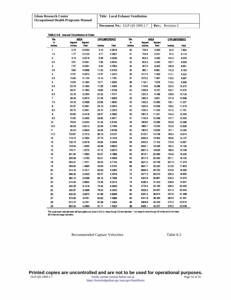
Area (A).—Surface area of a hood opening or duct; measured as round duct A = 3.14 (radius)2 or A =
0.79(diameter)2; typically measured as rectangular duct A = (length) (width) in square feet (ft2)
Duct.—Passageway made of sheet metal or other suitable material used for conveying air, gasses, vapors,
particulates, mist, or fumes
Local exhaust ventilation (LEV).—Industrial ventilation system that captures and removes emitted contaminants
before they are released into the workplace environment
Pitot tube probe.—Type of probe that simultaneously measures the static pressure and total pressure within a duct,
thereby allowing the velocity pressure to be calculated.; velocity is proportional to the square root of the velocity
pressure times 4004.4 for dry air at 70 °F and a barometric pressure of 29.92 inches (in.) of mercury (Hg).
Thermal anemometer probe.—Type of probe used to measure velocity and depends upon the known thermal
capacitance of an airstream to cool the thermocouple (“hot wire”) once it has been heated
Velocity (V).—Time rate of movement of air in a given direction, typically measured as feet per minute (ft/min or
fpm), meters per second (m/sec), or miles per hour (mph)
Velocity, face.—Air velocity measured at the face opening of a hood or duct
Printed copies are uncontrolled and are not to be used for operational purposes. GLP-QS-1800.1.7 Verify current version before use at Page 11 of 35
https://knowledgeshare.grc.nasa.gov/bmslibrary
Glenn Research Center
Occupational Health Programs Manual
Title: Local Exhaust Ventilation
Document No.: GLP-QS-1800.1.7 Rev.: Revision C
Velocity, capture.—Velocity of the air induced by a hood to capture emitted contaminants external to the hood;
acceptable capture velocity depends upon the mass of the contaminant being captured, the prevailing air currents
nearby, thermal properties of the contaminant (e.g., hot fumes rise), and the velocity of the contaminant relative to
hood flow (e.g., belt sander throwing dust into or away from its exhaust duct).
Volumetric flow rate (Q).—Volume or quantity of air that passes a given location per unit of time and that is
related to the average velocity and cross-sectional area by Q = VA
3.0 DISCUSSION
Local exhaust ventilation, or process exhaust, systems are used throughout industrial and laboratory environments to
move airborne contaminants away from workers to minimize their exposures. These systems must be designed to
not only handle the type and quantity of contaminant being generated but also to accommodate the employee and
work activities associated with the task. LEV systems are composed of several components that include the hood,
ducting, air mover, and possibly some type of contaminant removal mechanism. The design of such systems must
also take into account the facility where the LEV will be located and the other ventilation systems therein. The
design and layout of LEV systems is performed by Facilities Division engineering staff with input from a facility
team industrial hygienist (IH).
Evaluating the performance and adequacy of process exhaust systems at the worker-LEV interface is performed by
industrial hygiene staff. Many parameters must be considered when determining the flow velocity and rate necessary
to adequately remove a contaminant from a work zone and successfully transport it through the ventilation system.
Considerations include contaminant type (particle or gas), particle size (if not a gas), contaminant temperature,
contaminant initial velocity (speed and direction), ambient air movement, hood type, hood location, and worker
location. Periodic checks of the LEV system are used to compare system performance to the established flow
parameters and also to determine if the system/equipment setup has changed, necessitating the establishment of new
flow parameters.
4.0 Safety Precautions
Testing of local exhaust ventilation systems can involve potential safety and health hazards that must be managed
appropriately. When there are questions regarding the LEV system or equipment, IH personnel should contact the
individual responsible for the LEV system, experimental rig, or facility/room as needed.
Safety considerations associated with surveying LEV systems include those related to working on step ladders or
step stools to make flow measurements, entering areas with industrial safety hazards (foot, hand, eye , etc.), and any
potential safety hazards presented by the experiment/equipment or materials being stored or used. Managing such
hazards involves following prescribed precautions and wearing appropriate personal protective equipment (PPE).
Potential occupational health (OH) hazards associated with testing LEV systems will vary and depend upon the
status of the contaminant-generating activity or material/chemical storage/use and the efficacy of the ventilation
system. The surrounding work environment could also present OH concerns that should be considered (e.g., high
noise, lasers) Again, these hazards can be managed by using appropriate PPE and by following any specifically
prescribed safety precautions in addition to observing the general work practices associated with working in a
research environment.
5.0 Tools, Equipment and Materials
5.1 TSI VelociCalc® Air Velocity Meter
This meter measures velocity and temperature, calculates flow rate, performs multivalue averaging, and determines
minimum and maximum readings. Prior to use, this instrument shall have a current annual calibration sticker and
appear to be functioning properly.
5.2 TSI VelociCalc® Plus Multi-Parameter Ventilation Meter
This meter simultaneously measures and data logs several ventilation parameters using a single probe with multiple
sensors. The ventilation meter measures temperature, humidity, and pressure. The meter also features automatic
Printed copies are uncontrolled and are not to be used for operational purposes. GLP-QS-1800.1.7 Verify current version before use at Page 12 of 35
https://knowledgeshare.grc.nasa.gov/bmslibrary
Glenn Research Center
Occupational Health Programs Manual
Title: Local Exhaust Ventilation
Document No.: GLP-QS-1800.1.7 Rev.: Revision C
calculation of flow rate and automatic conversion between actual and standard velocity readings. Prior to use, this
instrument shall have a current annual calibration sticker and appear to be functioning properly.
Reserved for alternate venation meter
Smoke tube kit that generates vapor/fume for visualizing flow of LEV systems
Vinyl tag holders and miscellaneous administrative supplies
Tape measure and miscellaneous tools (adjustable wrench, screwdriver)
5.3 Additional Equipment
Smoke tube kit that generates vapor/fume for visualizing flow of LEV systems
Vinyl tag holders and miscellaneous administrative supplies
Tape measure and miscellaneous tools (adjustable wrench, screwdriver)
6.0 RESPONSIBILITIES
6.1 Industrial Hygiene Personnel
Personnel performing industrial hygiene functions within GRC’s Safety, Health and Environmental
Division (SHED) are responsible for being familiar with and implementing this work instruction.
7.0 PERSONNEL TRAINING AND/OR CERTIFICATION
Industrial hygiene personnel who perform local exhaust ventilation system surveys should have received
the necessary training associated with entering most areas at the Center.
Industrial hygiene personnel who perform local exhaust ventilation system surveys should have a general
understanding of ventilation systems and flow parameter calculations.
Industrial hygiene personnel who perform local exhaust ventilation system surveys should know how to
operate survey equipment and be familiar with the equipment manuals.
8.0 INSTRUCTIONS
8.1 Administrative and Data Management Functions
8.1.1 Database
An Access database is used to track local exhaust ventilation systems at GRC. Information in this database includes
a unique identifying number for the LEV system, point of contact, type of system, operating parameters (i.e., flow
specifications), face or capture velocity (or observed reading), distance from face, and comments. In addition,
images are being added to the database to aid in identifying each system and where and how the flow measurements
should be secured. Standard database functions are used to sort, query, and, otherwise, manage the LEV system
information. It is important that IH personnel actively maintain this data resource to reflect changes in system
information or the performance of periodic surveys.
The fields “operating parameter” and “comments” should be used to provide specific instruction on how and where
the flow parameter should be measured, what the requirement is, and, if needed, a description of how this flow
requirement was determined.
8.1.2 Naming Convention
LEV systems are uniquely identified using the following convention:
Building No. – Room/Cell No. – Hood No.
Examples: 302 – 219 – 5
005 – CW5 – 2
Printed copies are uncontrolled and are not to be used for operational purposes. GLP-QS-1800.1.7 Verify current version before use at Page 13 of 35
https://knowledgeshare.grc.nasa.gov/bmslibrary
Glenn Research Center
Occupational Health Programs Manual
Title: Local Exhaust Ventilation
Document No.: GLP-QS-1800.1.7 Rev.: Revision C
Hoods are numbered sequentially, with there being no significance or priority associated with the actual number.
When a new LEV system is added to a room, it receives the next available unused number. Numbers for systems
that have been removed from a room or cell are decommissioned with the system and are not reused.
8.2 Establishing Required Flow Parameters
8.2.1 General Discussion
Velocity and/or flow requirements for some LEV system types can come straight from OSHA regulations or directly
out of industry guidelines, such as the ACGIH manual Industrial Ventilation, A Manual of Recommended Practice
for Design, hereinafter identified as the “Ventilation Manual.” The manufacturer of the equipment being ventilated
by the LEV system may also provide a specification for process exhaust performance. Establishing flow
requirements for many other systems will depend upon assessing the LEV application along with its target activity
using guidance provided in relevant ventilation references.
Although not an exhaustive list, the following guidance is intended to address most of the LEV system types found
at GRC. Other LEV applications might require a bit of researching and the application of general principles to
establish its flow requirements. In addition, changes to prescribed flow parameters might be allowable to address
unusual LEV needs.
Once established, the flow requirements for an LEV system along with supporting information shall be recorded in
the database operating parameter field and the comments field, respectively.
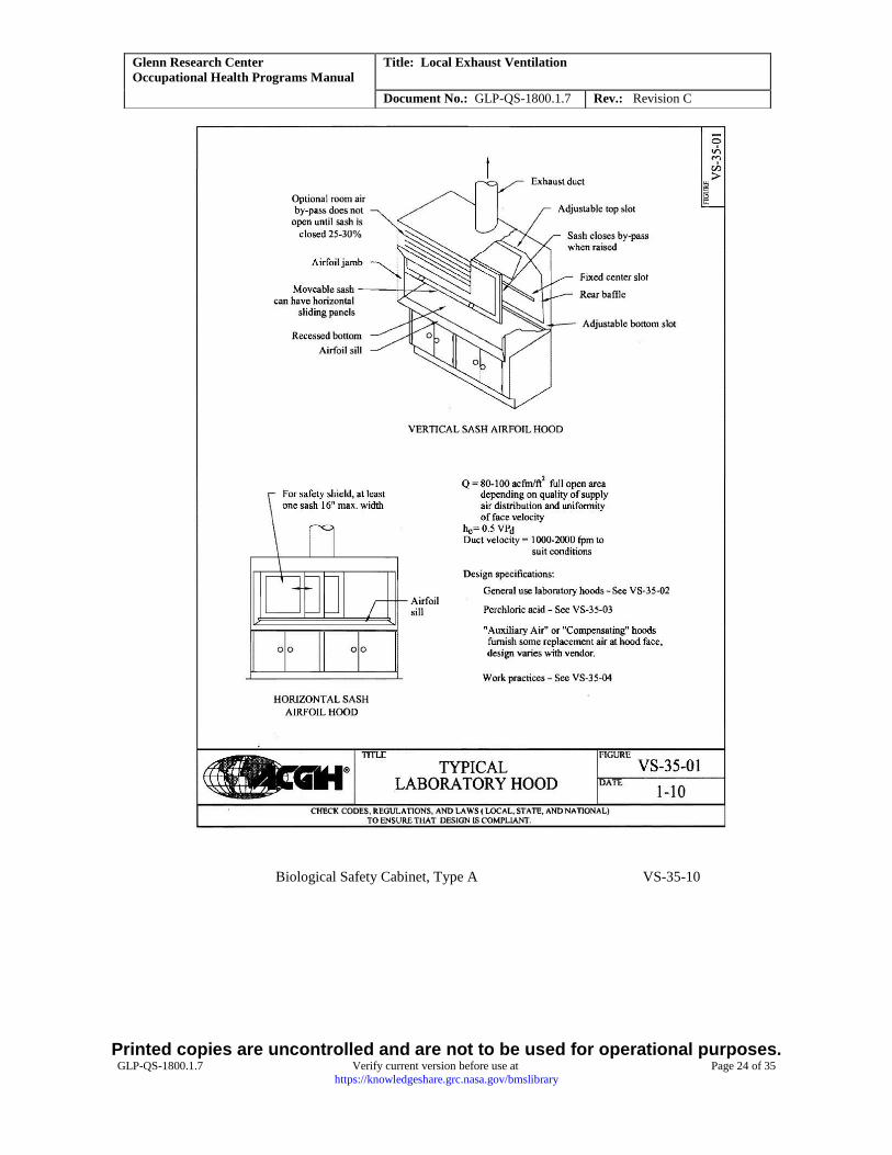
8.2.2 Laboratory Fume Hood
The average face velocity of nine readings (33) taken over the laboratory hood opening should range between 80
and 120 fpm, with a target value of 100 fpm.
If the LEV system is a continuous-flow laboratory fume hood, the hood shall provide a face velocity of 100 ft/min
(fpm) ±20 percent. If the LEV system is not a continuous-flow laboratory fume hood, then the sash shall be adjusted
such that the hood provides a face velocity of 100 fpm ±20 percent. The sash height shall be marked on the survey
tag or on the hood itself to clearly indicate the required sash height. Hoods that are equipped with airflow
monitoring gauges must indicate the tested velocity flow within ±10 percent. If not, a WR must be submitted to
address the discrepancy.
Newly purchased laboratory fume hoods shall include a continuous face velocity monitor for the purpose of
measuring hood performance. Each monitor shall be calibrated annually.
Laboratory hoods should not be used for general chemical storage. Keep materials stored in hoods to a minimum
and do not allow them to block vents or airflow.
Refer to the Ventilation Manual pages 6-3>16, 13-47>52 and figures VS-35-01>04 for further details on laboratory
fume hood design (Appendix C).
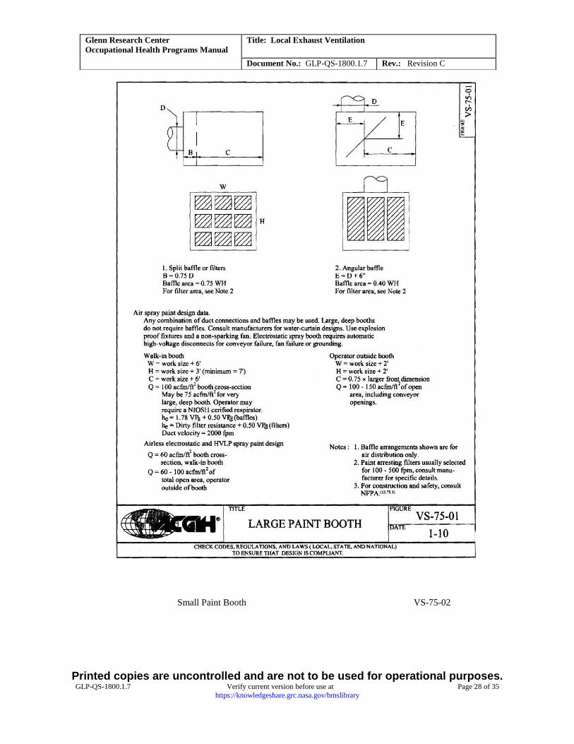
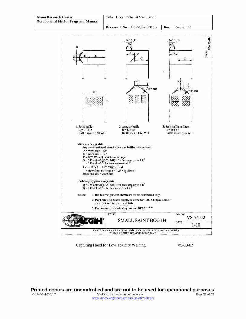
Note: Laboratory fume hoods and paint spray booths are not created equal. A paint spray booth is a specifically
designed enclosure for the control of paint vapors and particulate overspray, equipped with air filtration to contain
emissions and protect against combustible paint film buildup in ductwork, and includes fire suppression. Often,
laboratory fume hoods do not meet this criteria. Air flow recommendations for paint booths also vary. Refer to
Ventilation Manual figures VS-75-01>02 for further details (Appendix C).
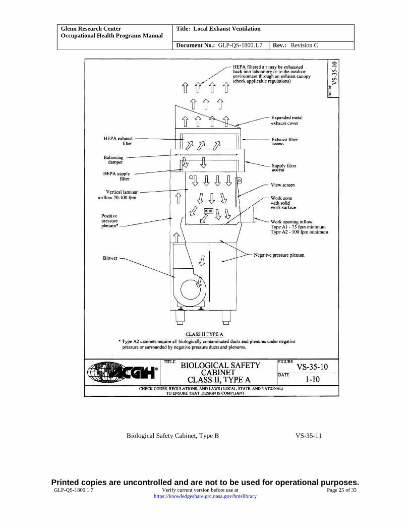
8.2.3 Biological Safety Cabinets
Biological safety cabinets require annual recertification according to National Science Foundation (NSF) American
National Standards Institute (ANSI) International Standard Number 49 for downflow, inflow, flowpattern, and
system leakage integrity. This procedure shall be accomplished by an NSF Accredited Class II Biosafety Cabinet
Certifier. Please refer to the Industrial Ventilation Manual figures VS-35-1- and VS-35-11 for further details on
cabinet design considerations (Appendix C) and for complete biosafety considerations in “Biosafety in
Microbiological and Biomedical Laboratories (BMBL) 5th Edition, HHS Publication No. (CDC) 21-1112, 2009.
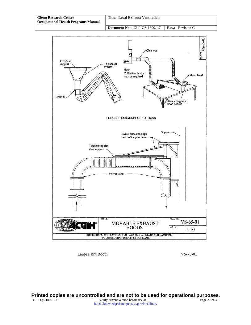
8.2.4 Snorkel-Type Hood (Articulated Arm)
Printed copies are uncontrolled and are not to be used for operational purposes. GLP-QS-1800.1.7 Verify current version before use at Page 14 of 35
https://knowledgeshare.grc.nasa.gov/bmslibrary
Glenn Research Center
Occupational Health Programs Manual
Title: Local Exhaust Ventilation
Document No.: GLP-QS-1800.1.7 Rev.: Revision C
The flow requirement for this system will depend on the characteristics of the contaminant and the distance from the
point of contaminant generation to the hood opening. Typically, the hood shall be as close to this point as possible
without interfering with the work task or otherwise creating another safety hazard. The flow specification can be
either a capture velocity at a specified distance from the hood to reflect the work scenario or a face velocity at the
hood or duct to correspond to this needed capture velocity. Note that the face velocity required to achieve a specific
capture velocity at some distance X increases very rapidly as the distance X gets larger. Please refer to Ventilation
Manual pages 6-18>24, 13-103>104, and 13-165>168 and figures VS-65-01 and VS-90-02 for further details
(Appendix C).
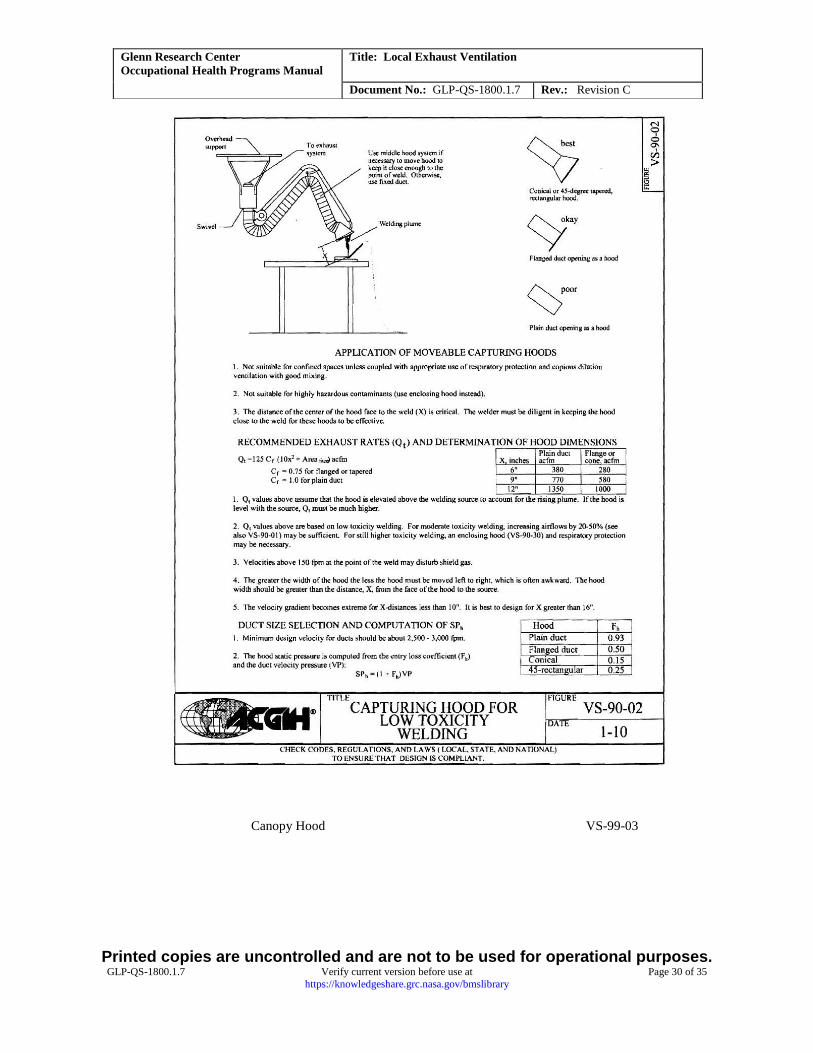
Example Welding Operation
LEV uses a 6-in.-diameter flexible duct, and the hood expands to a diameter of 12”. . The welding operation is 9 in.
from the face of the hood.
Assume a required capture velocity Q of 150 fpm for welding low-toxicity materials in moderately still air
(Ventilation Manual, VS–90–2, 2010).
Q = 150 Cf (10X2 + A) (Ventilation Manual, VS–90–2, 2010), where Cf = 0.75 for tapered duct, X = distance from
hood to capture point, A = cross-sectional area of hood opening Q = 150 fpm × 0.75 × [10 × (9/12)2 ft2+ 0.7854 ft2]
= 721 ft3/min (cfm) Note that the area A of an 12” circle is 0.7854 square feet.
The corresponding hood face velocity V = Q/A = (721 cfm)/(0.7854 ft2) = 918 fpm
The corresponding duct face velocity V = (721 cfm)/(0.2 ft2) = 3605 fpm
This example shows three possible velocity measurements that could be made to check the performance of such an
LEV system: capture velocity = 150 fpm (minimum), hood face velocity = 918 fpm, and duct face velocity = 3605
fpm. [only pertains to a specified capture velocity of 150 fpm and a hood location 9” from the point of fume
generation, with a 12” hood and 6” duct opening]
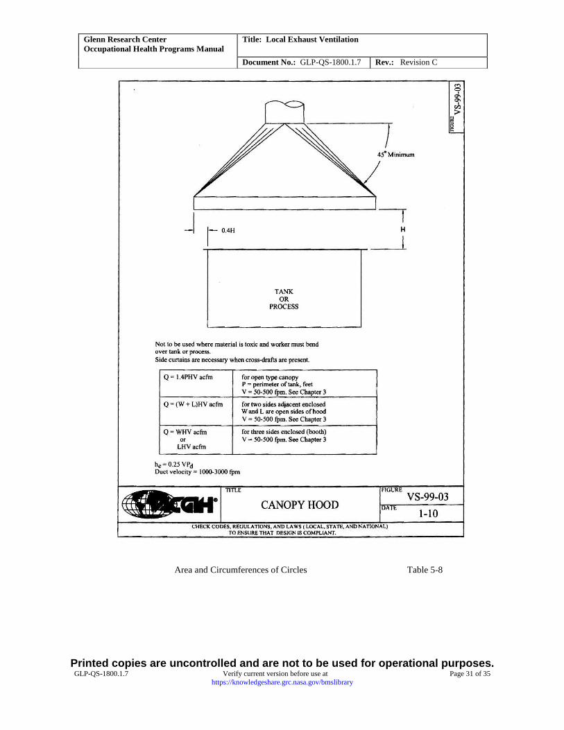
8.2.5 Canopy Hood
Flow requirements depend not only on the characteristic of the contaminant generated and the distance to the hood
but on the type of canopy hood (open sides = 4, 3, 2, or 1). Because of this openness, their size, and the distance to
the target activity, canopy hoods are not very efficient means of contaminant removal. Consequently, significant
flow may be necessary to properly remove the emission from the work environment. Canopy hoods shall provide a
capture velocity based on source toxicity, distance from contaminant source, temperature of process and cross drafts.
Refer to Ventilation Manual pages 6-18>20, 13-35>40, and 13-110>113, and figure VS-99-03 for further details
(Appendix C).
Example Canopy Hood Operation
The canopy hood is above an oven where hot emissions are released in an environment of relatively still air. The
oven has a foot print of 2 by 2 ft. The canopy profile is 3 by 3 ft; the hood is open on all four sides, and the bottom
of the canopy is 1 ft above the top of the oven. The canopy hood is attached to 8-in.-diameter ductwork.
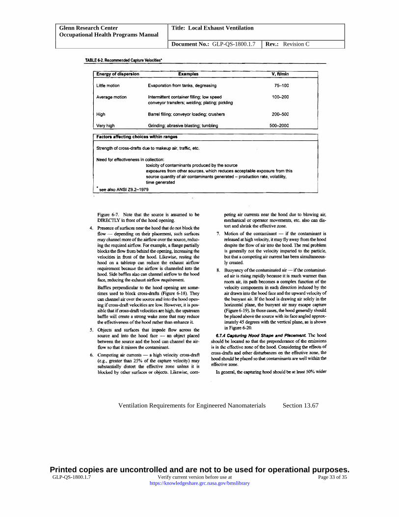
Assume a required capture velocity Q of 75 fpm for hot effluent into quiet air (Ventilation Manual, Table 6–2). Q =
1.4 PHV (Ventilation Manual, VS–99–3, 2010), where P = emission source (oven) perimeter, H = distance from
bottom of canopy to target zone
Q = 1.4 × (8 ft) × (1 ft) × (75 ft/min) = 840 cfm
The corresponding hood face velocity V = (840 cfm)/(9ft2) = 93 fpm
The corresponding duct face velocity V = (840 cfm)/(0.349) ft2) = 2406 fpm
Three choices for velocity measurements can be made to check the performance of such an LEV system: capture
velocity = 75 fpm (minimum), hood face velocity of 93 fpm, and duct face velocity = 2406 fpm.
8.2.6 Cabinet
The flow requirements for a cabinet-style LEV system are logically somewhat lower than an those for an open-type
LEV hood because the target volume is enclosed on all sides. A capture velocity can be selected from Table 6-2 of
Printed copies are uncontrolled and are not to be used for operational purposes. GLP-QS-1800.1.7 Verify current version before use at Page 15 of 35
https://knowledgeshare.grc.nasa.gov/bmslibrary
Glenn Research Center
Occupational Health Programs Manual
Title: Local Exhaust Ventilation
Document No.: GLP-QS-1800.1.7 Rev.: Revision C
the Ventilation Manual (See Appendix C) and the calculations made to determine the corresponding duct face
velocity (cabinet outlet) or filter/slot panel velocity (cabinet inlet).
Example Cabinet Operation
A ventilated cabinet houses an activity involving a high-intensity ultraviolet xenon lamp; ozone (O3) production is
expected. The cabinet width and depth are both 2 ft. The cabinet has a 4-in.-diameter exhaust at the top on its back
panel and a 6- by 12-in. filtered inlet near the bottom of the front panel.
Assume a required capture velocity of 25 fpm for the emission of a gas in a quiet, enclosed cabinet. Q = VA
Q = (25 fpm) × (2 ft) × (2 ft) = 100 cfm
The corresponding duct face velocity V = (100 cfm)/(0.09 ft2) = 1150 ft/min
The corresponding filter inlet face velocity, V = (100 cfm)/(0.5 ft2) = 200 ft/min
Depending upon accessibility, there may be up to three choices for making a measurement to check the performance
of this system; the least intrusive would be a measurement of the inlet filter face velocity, which has a minimum
specification of 200 fpm.
8.2.7 Sander/Grinder
The particles generated in these mechanical abrasion operations are relatively large and require high capture and
duct velocities to grab the contaminant and keep it suspended during transport. Table 6–1 of the ventilation manual
specified a minimum capture velocity of 500 to 2000 fpm for contaminants released at a high initial velocity into a
zone of very rapid air motion (e.g., grinding). Other flow requirements for a sanding/grinding operation are specified
based upon the type of operation and the size of the abrading media. Typical operation types include wheel, belt, and
disk with pertinent dimensions being wheel width, belt width, and disk diameter. These flow requirements are
specified as minimum exhaust flow rates in cubic feet per minute. Assigning a flow requirement for a particular
system will depend upon how best to make a relevant and meaningful measurement.
8.2.8 Other
In general, establishing a capture velocity parameter for an LEV system based upon the operation being ventilated is
the best approach for evaluating the effectiveness and performance of such a system. Ranges of capture velocities
for many applications can be found in references such as the Ventilation Manual, but often a decision must be made
to establish a flow requirement not covered by such a reference. In some cases, experience and professional
judgment may be adequate to establish a minimum capture velocity. In other cases, personal exposure monitoring
may be necessary to assess the adequacy of an LEV system.
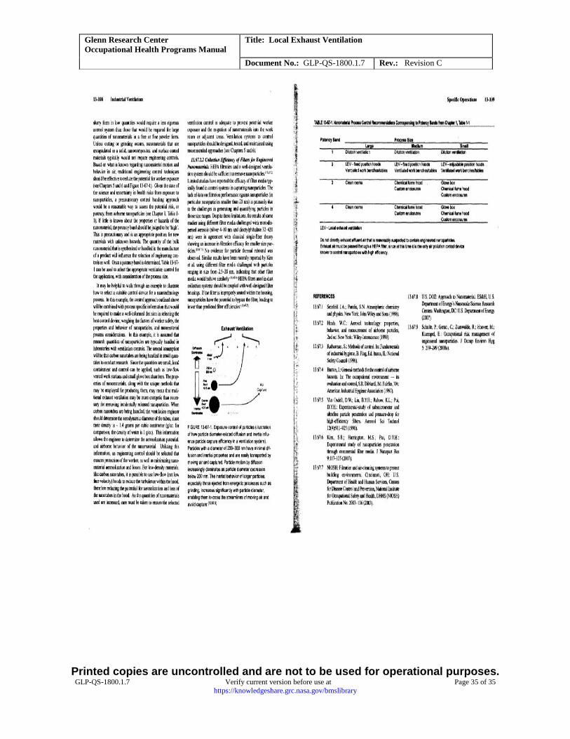
Engineered Nanomaterials Ventilation Requirements for Engineered Nanomaterials are covered in Section 13.67 of
the Industrial Ventilation manual (See Appendix C). Nanoparticles have unknown human health effects due to
unique chemical and physical properties including particle size, shape, surface area, charge, chemical properties,
solubility, oxidant generation potential, and degree of agglomeration.
8.3 Performing LEV System Surveys
8.3.1 General Discussion
Prior to performing LEV system assessments, the surveyor should ensure that the instrument is calibrated and
appears to functioning properly. The surveyor should also verify that the subject LEV system is operating and make
note of any pertinent valve/damper positions and other conditions of the mechanical ventilation system. Inspect the
exhaust system and its associated ductwork and mechanical components for any obvious signs of damage or other
problems. (e.g., clogged ductwork or intake, breached ductwork, broken dampers, missing or damaged seals,
unusually loud motor noises or oscillations). Do not test the LEV system if it is not operable or is of questionable
integrity. Raise concerns about the system with the system point of contact and/or facility personnel.
The surveyor should record as much information about the testing scenario as is necessary to properly document the
LEV system’s compliance with performance specifications and to allow for reproducible measurements to be taken
in the future. This information shall include distances from duct faces where capture velocity measurements were
Printed copies are uncontrolled and are not to be used for operational purposes. GLP-QS-1800.1.7 Verify current version before use at Page 16 of 35
https://knowledgeshare.grc.nasa.gov/bmslibrary
Glenn Research Center
Occupational Health Programs Manual
Title: Local Exhaust Ventilation
Document No.: GLP-QS-1800.1.7 Rev.: Revision C
taken, damper positions (when applicable), the type of contaminant generated, pertinent dimensions of the
system/layout, assumptions made that impacted testing, and so forth.
Although the purpose of the LEV surveys is to verify proper operation of the process exhaust system, the tools and
methods being used can also be used to optimize systems or work scenarios that do not meet their flow
specifications. Tracing smoke and measuring flow velocities can be used to identify the boundaries of an appropriate
work zone for an LEV system or identify items that adversely impact the performance of such a system.
8.3.2 Use of Smoke Tubes
The vapor and/or fume generated by a smoke tube provides a convenient method for visualizing airflow. The value
of this tool in assessing the performance of an LEV system is somewhat limited because of the subjective nature of
the method and its result. Its use can be considered for a qualitative assessment of systems where flow adequacy is
easily achieved and other flow parameters are difficult to measure. One example could be a toxic material storage
cabinet whose exhaust is intended to remove contaminants resulting from a small leak. In this instance, the smoke
can be used (1) near the door while slightly cracking the door open or (2) near an intake panel, if present. Another
use would be an enclosed bead/sand blasting unit where the smoke could be used to check the integrity of enclosure
seals or to determine if the exhaust system is adequately drawing or sucking on the box to keep this work volume
negative in pressure relative to where the blaster operators are located.
8.3.3 Use of the Thermal Anemometer Probe [Do not use in explosive, flammable or combustible
atmospheres]
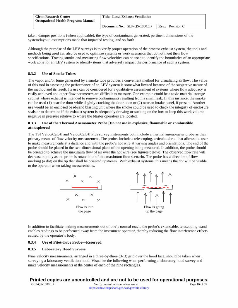
The TSI VelociCalc® and VelociCalc® Plus survey instruments both include a thermal anemometer probe as their
primary means of flow velocity measurement. The probes include a telescoping, articulated rod that allows the user
to make measurements at a distance and with the probe’s hot wire at varying angles and orientations. The end of the
probe should be placed in the two-dimensional plane of the opening being measured. In addition, the probe should
be oriented to achieve the maximum flow of air over the hot wire (see figures below). The observed flow rate will
decrease rapidly as the probe is rotated out of this maximum flow scenario. The probe has a direction of flow
marking (a dot) on the tip that shall be oriented upstream. With exhaust systems, this means the dot will be visible
to the operator when taking measurements.
In addition to facilitate making measurements out of one’s normal reach, the probe’s extendable, telescoping wand
enables readings to be performed away from the instrument operator, thereby reducing the flow interference effects
caused by the operator’s body.
8.3.4 Use of Pitot-Tube Probe—Reserved.
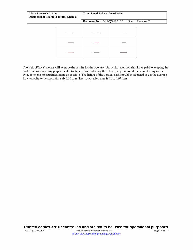
8.3.5 Laboratory Hood Surveys
Nine velocity measurements, arranged in a three-by-three (33) grid over the hood face, should be taken when
surveying a laboratory ventilation hood. Visualize the following when performing a laboratory hood survey and
make velocity measurements at the center of each of the nine rectangles.
Flow is into
the page
Flow is going
up the page
Printed copies are uncontrolled and are not to be used for operational purposes. GLP-QS-1800.1.7 Verify current version before use at Page 17 of 35
https://knowledgeshare.grc.nasa.gov/bmslibrary
Glenn Research Center
Occupational Health Programs Manual
Title: Local Exhaust Ventilation
Document No.: GLP-QS-1800.1.7 Rev.: Revision C
The VelociCalc® meters will average the results for the operator. Particular attention should be paid to keeping the
probe hot-wire opening perpendicular to the airflow and using the telescoping feature of the wand to stay as far
away from the measurement zone as possible. The height of the vertical sash should be adjusted to get the average
flow velocity to be approximately 100 fpm. The acceptable range is 80 to 120 fpm.
Printed copies are uncontrolled and are not to be used for operational purposes. GLP-QS-1800.1.7 Verify current version before use at Page 18 of 35
https://knowledgeshare.grc.nasa.gov/bmslibrary
Glenn Research Center
Occupational Health Programs Manual
Title: Local Exhaust Ventilation
Document No.: GLP-QS-1800.1.7 Rev.: Revision C
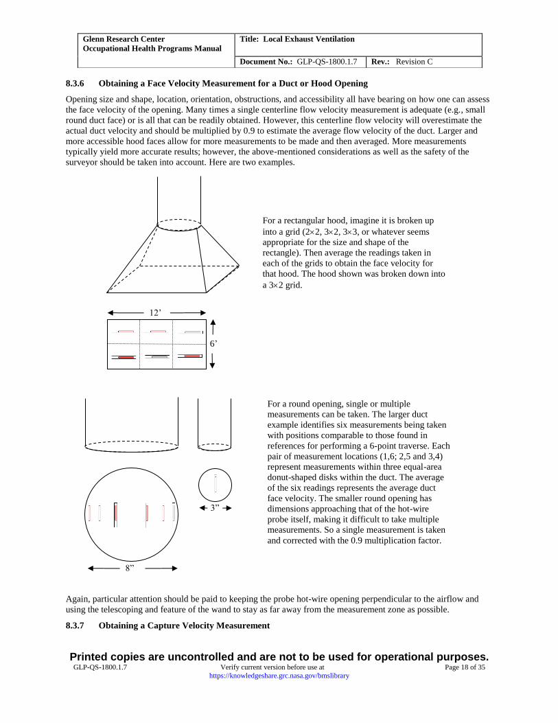
8.3.6 Obtaining a Face Velocity Measurement for a Duct or Hood Opening
Opening size and shape, location, orientation, obstructions, and accessibility all have bearing on how one can assess
the face velocity of the opening. Many times a single centerline flow velocity measurement is adequate (e.g., small
round duct face) or is all that can be readily obtained. However, this centerline flow velocity will overestimate the
actual duct velocity and should be multiplied by 0.9 to estimate the average flow velocity of the duct. Larger and
more accessible hood faces allow for more measurements to be made and then averaged. More measurements
typically yield more accurate results; however, the above-mentioned considerations as well as the safety of the
surveyor should be taken into account. Here are two examples.
Again, particular attention should be paid to keeping the probe hot-wire opening perpendicular to the airflow and
using the telescoping and feature of the wand to stay as far away from the measurement zone as possible.
8.3.7 Obtaining a Capture Velocity Measurement
6’
12’
For a rectangular hood, imagine it is broken up
into a grid (22, 32, 33, or whatever seems
appropriate for the size and shape of the
rectangle). Then average the readings taken in
each of the grids to obtain the face velocity for
that hood. The hood shown was broken down into
a 32 grid.
8”
For a round opening, single or multiple
measurements can be taken. The larger duct
example identifies six measurements being taken
with positions comparable to those found in
references for performing a 6-point traverse. Each
pair of measurement locations (1,6; 2,5 and 3,4)
represent measurements within three equal-area
donut-shaped disks within the duct. The average
of the six readings represents the average duct
face velocity. The smaller round opening has
dimensions approaching that of the hot-wire
probe itself, making it difficult to take multiple
measurements. So a single measurement is taken
and corrected with the 0.9 multiplication factor.
3”
Printed copies are uncontrolled and are not to be used for operational purposes. GLP-QS-1800.1.7 Verify current version before use at Page 19 of 35
https://knowledgeshare.grc.nasa.gov/bmslibrary
Glenn Research Center
Occupational Health Programs Manual
Title: Local Exhaust Ventilation
Document No.: GLP-QS-1800.1.7 Rev.: Revision C
When possible, a capture velocity reading is the best measure of the effectiveness of an LEV system because the
surveyor is observing the flow effects experienced by the contaminant itself. Often, however, such measurements
are difficult to make because of limited accessibility (enclosures, obstructions), requiring that some other surrogate
measurement (e.g., duct face velocity) be made. When using the thermal anemometer to make these measurements,
the probe’s articulating and telescoping features should be utilized to keep the hot-wire opening (1) perpendicular to
the airflow and (2) away from interference created by the surveyor.
8.4 LEV System Results: Tags and Documentation
8.4.1 General Discussion
The documentation of LEV survey results involves displaying results locally at the LEV system and recording the
results in the LEV database. Both modes play an important role in ensuring the health of workers relying on such
engineering controls. Local postings describe whether the system is functioning properly, if there are restrictions on
its use (e.g., maximum sash height of a lab hood or maximum effective range of a snorkel hood), or if there are
requirements to be met prior to using the system for worker protection.
8.4.2 Recording Results Locally at LEV system
A system of multicolor tags will be used to document survey results in the field. These tags will replace the
fluorescent orange “Survey” tags and red “Do Not Use” postings being used as of May 2007. In most instances, the
colored tags will fit into vinyl sleeves that will be placed (using Velcro® or other adhesion method) on the LEV
system to allow conspicuous viewing of the colored tags. For LEV systems where this is not possible, a brass
grommet is to be added to the vinyl sleeve that will then be hung at the LEV system, again in a location to allow
conspicuous viewing of the tag. In addition, sash-height labels will be placed on the side of laboratory fume hoods to
identify the required position at the bottom of the sliding vertical sash.
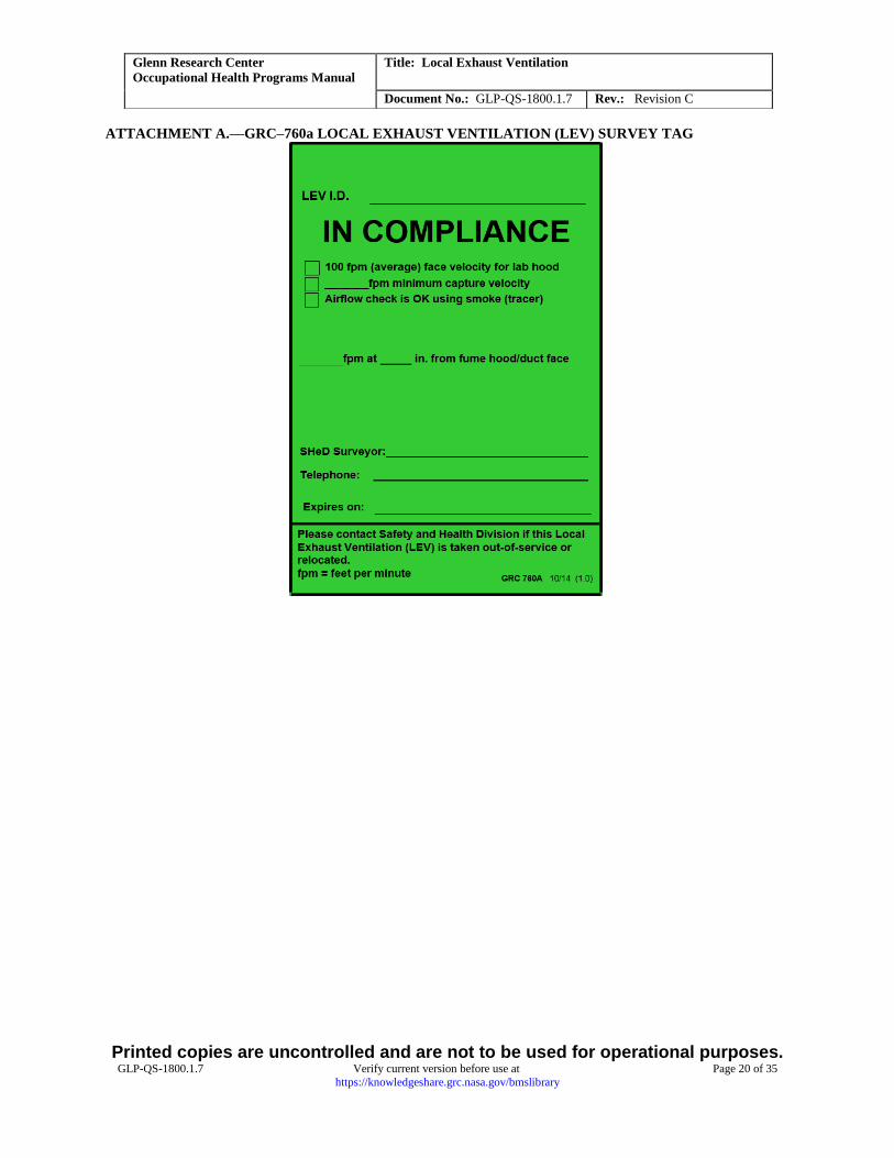
8.4.2.1 Green LEV Survey Tag
The green “LEV Survey Tag” shown in Attachment A is to be used when survey results satisfy the system flow
requirements. Tags are filled in to identify the system, document the survey results, and list any restrictions
associated with the LEV system use. An example of a use restriction would be specifying a maximum effective
range of 8 in. for a flexible snorkel being used for welding activities.
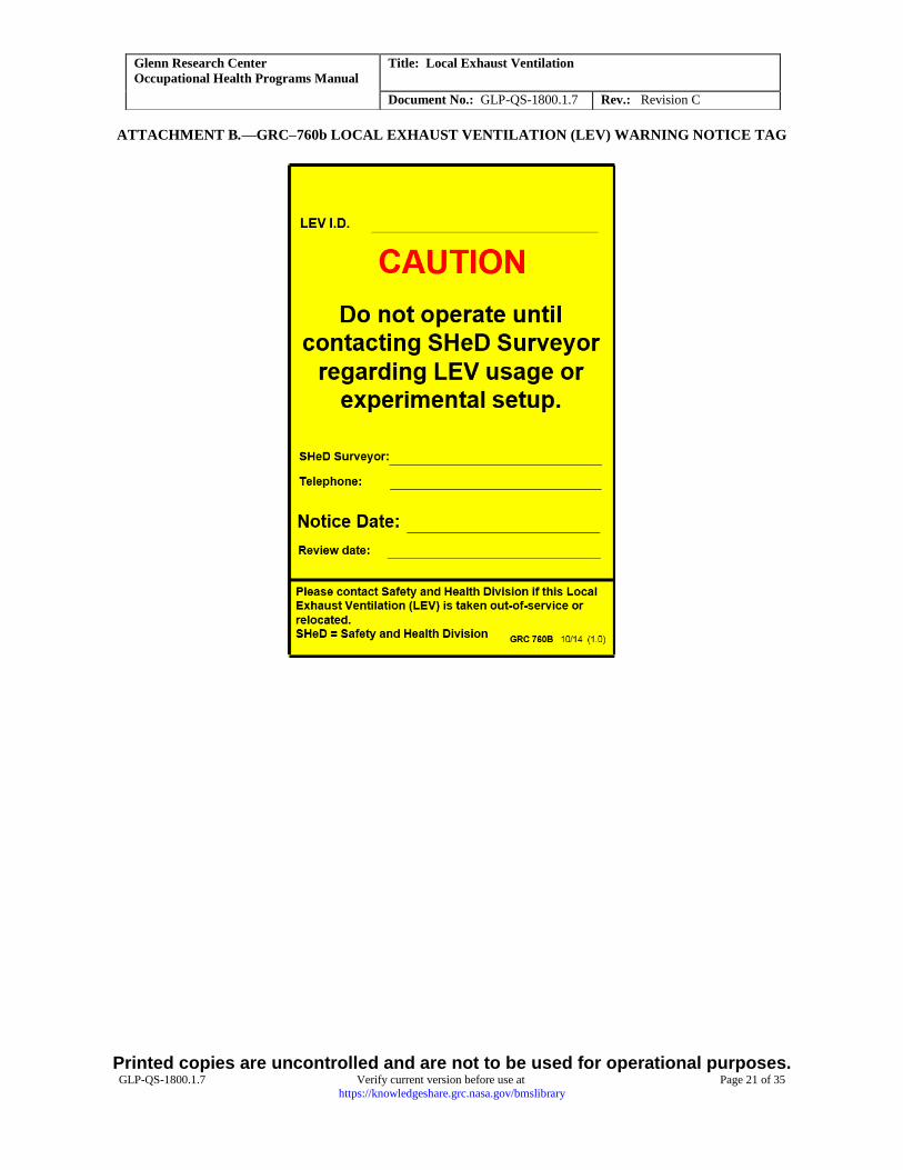
8.4.2.2 Yellow LEV Warning Notice Tag
The yellow “LEV Warning Notice Tag” shown in Attachment B is to be used when there is inadequate information
to verify the efficacy of the system. The hood ID and any other relevant comments are to be included on the tag. For
example, a canopy hood or duct drop is positioned over an area that has no source of contaminant emission. Without
knowing the emission characteristics and distances involved, it would not be possible to adequately assess the
adequacy of such an LEV system.
8.4.2.3 Red LEV Out of Service Notice Tag
The red “LEV Out of Service Notice Tag” shown in Attachment C is to be used when survey results do not satisfy
the system flow requirements. The hood ID and any other relevant comments are to be included on the tag. After
placing a red out of service (OOS) notice on a system, the surveyor shall contact the LEV system point of contact or
local facility personnel to discuss the deficiency. When needed, an industrial hygienist shall be contacted to evaluate
the LEV system with input from the user, facility, and maintenance personnel.
8.4.3 Updating Database
The LEV system database allows for storage of system information, testing requirements, and survey results.
Typical database features such as sorting, querying, and report generating allow for convenient data manipulation
and display. Following an LEV system survey, the fields within the unique record for that particular system are to be
updated to reflect the survey results, date, surveyor, and if not already identified, the survey conditions and specific
flow requirements and any relevant assumptions in establishing the criteria.
Printed copies are uncontrolled and are not to be used for operational purposes. GLP-QS-1800.1.7 Verify current version before use at Page 20 of 35
https://knowledgeshare.grc.nasa.gov/bmslibrary
Glenn Research Center
Occupational Health Programs Manual
Title: Local Exhaust Ventilation
Document No.: GLP-QS-1800.1.7 Rev.: Revision C
ATTACHMENT A.—GRC–760a LOCAL EXHAUST VENTILATION (LEV) SURVEY TAG
Printed copies are uncontrolled and are not to be used for operational purposes. GLP-QS-1800.1.7 Verify current version before use at Page 21 of 35
https://knowledgeshare.grc.nasa.gov/bmslibrary
Glenn Research Center
Occupational Health Programs Manual
Title: Local Exhaust Ventilation
Document No.: GLP-QS-1800.1.7 Rev.: Revision C
ATTACHMENT B.—GRC–760b LOCAL EXHAUST VENTILATION (LEV) WARNING NOTICE TAG

Printed copies are uncontrolled and are not to be used for operational purposes. GLP-QS-1800.1.7 Verify current version before use at Page 22 of 35
https://knowledgeshare.grc.nasa.gov/bmslibrary
Glenn Research Center
Occupational Health Programs Manual
Title: Local Exhaust Ventilation
Document No.: GLP-QS-1800.1.7 Rev.: Revision C
ATTACHMENT C.—GRC–760c LOCAL EXHAUST VENTILATION (LEV) OUT OF SERVICE NOTICE
TAG
APPENDIX C—INDUSTRIAL VENTILATION: A MANUAL OF RECOMMENDED PRACTICE FOR DESIGN,
27TH EDITION FIGURES:
TITLE FIGURE/TABLE/SECTION
Laboratory Hood VS-35-01
Biological Safety Cabinet, Type A VS-35-10
Biological Safety Cabinet, Type B VS-35-11
Movable Exhaust Hoods VS-65-01
Large Paint Booth VS-75-01
Small Paint Booth VS-75-02
Capturing Hood for Low Toxicity Welding VS-90-02
Printed copies are uncontrolled and are not to be used for operational purposes. GLP-QS-1800.1.7 Verify current version before use at Page 23 of 35
https://knowledgeshare.grc.nasa.gov/bmslibrary
Glenn Research Center
Occupational Health Programs Manual
Title: Local Exhaust Ventilation
Document No.: GLP-QS-1800.1.7 Rev.: Revision C
Canopy Hood VS-99-03
Area and Circumferences of Circles Table 5-8
Recommended Capture Velocities Table 6-2
Ventilation Requirements for Engineered Nanomaterials Section 13.67
Laboratory Hood VS-35-01
Printed copies are uncontrolled and are not to be used for operational purposes. GLP-QS-1800.1.7 Verify current version before use at Page 24 of 35
https://knowledgeshare.grc.nasa.gov/bmslibrary
Glenn Research Center
Occupational Health Programs Manual
Title: Local Exhaust Ventilation
Document No.: GLP-QS-1800.1.7 Rev.: Revision C
Biological Safety Cabinet, Type A VS-35-10
Printed copies are uncontrolled and are not to be used for operational purposes. GLP-QS-1800.1.7 Verify current version before use at Page 25 of 35
https://knowledgeshare.grc.nasa.gov/bmslibrary
Glenn Research Center
Occupational Health Programs Manual
Title: Local Exhaust Ventilation
Document No.: GLP-QS-1800.1.7 Rev.: Revision C
Biological Safety Cabinet, Type B VS-35-11

Printed copies are uncontrolled and are not to be used for operational purposes. GLP-QS-1800.1.7 Verify current version before use at Page 26 of 35
https://knowledgeshare.grc.nasa.gov/bmslibrary
Glenn Research Center
Occupational Health Programs Manual
Title: Local Exhaust Ventilation
Document No.: GLP-QS-1800.1.7 Rev.: Revision C
Movable Exhaust Hoods VS-65-01
Printed copies are uncontrolled and are not to be used for operational purposes. GLP-QS-1800.1.7 Verify current version before use at Page 27 of 35
https://knowledgeshare.grc.nasa.gov/bmslibrary
Glenn Research Center
Occupational Health Programs Manual
Title: Local Exhaust Ventilation
Document No.: GLP-QS-1800.1.7 Rev.: Revision C
Large Paint Booth VS-75-01
Printed copies are uncontrolled and are not to be used for operational purposes. GLP-QS-1800.1.7 Verify current version before use at Page 28 of 35
https://knowledgeshare.grc.nasa.gov/bmslibrary
Glenn Research Center
Occupational Health Programs Manual
Title: Local Exhaust Ventilation
Document No.: GLP-QS-1800.1.7 Rev.: Revision C
Small Paint Booth VS-75-02
Printed copies are uncontrolled and are not to be used for operational purposes. GLP-QS-1800.1.7 Verify current version before use at Page 29 of 35
https://knowledgeshare.grc.nasa.gov/bmslibrary
Glenn Research Center
Occupational Health Programs Manual
Title: Local Exhaust Ventilation
Document No.: GLP-QS-1800.1.7 Rev.: Revision C
Capturing Hood for Low Toxicity Welding VS-90-02
Printed copies are uncontrolled and are not to be used for operational purposes. GLP-QS-1800.1.7 Verify current version before use at Page 30 of 35
https://knowledgeshare.grc.nasa.gov/bmslibrary
Glenn Research Center
Occupational Health Programs Manual
Title: Local Exhaust Ventilation
Document No.: GLP-QS-1800.1.7 Rev.: Revision C
Canopy Hood VS-99-03
Printed copies are uncontrolled and are not to be used for operational purposes. GLP-QS-1800.1.7 Verify current version before use at Page 31 of 35
https://knowledgeshare.grc.nasa.gov/bmslibrary
Glenn Research Center
Occupational Health Programs Manual
Title: Local Exhaust Ventilation
Document No.: GLP-QS-1800.1.7 Rev.: Revision C
Area and Circumferences of Circles Table 5-8
Printed copies are uncontrolled and are not to be used for operational purposes. GLP-QS-1800.1.7 Verify current version before use at Page 32 of 35
https://knowledgeshare.grc.nasa.gov/bmslibrary
Glenn Research Center
Occupational Health Programs Manual
Title: Local Exhaust Ventilation
Document No.: GLP-QS-1800.1.7 Rev.: Revision C
Recommended Capture Velocities Table 6-2
Printed copies are uncontrolled and are not to be used for operational purposes. GLP-QS-1800.1.7 Verify current version before use at Page 33 of 35
https://knowledgeshare.grc.nasa.gov/bmslibrary
Glenn Research Center
Occupational Health Programs Manual
Title: Local Exhaust Ventilation
Document No.: GLP-QS-1800.1.7 Rev.: Revision C
Ventilation Requirements for Engineered Nanomaterials Section 13.67

Printed copies are uncontrolled and are not to be used for operational purposes. GLP-QS-1800.1.7 Verify current version before use at Page 34 of 35
https://knowledgeshare.grc.nasa.gov/bmslibrary
Glenn Research Center
Occupational Health Programs Manual
Title: Local Exhaust Ventilation
Document No.: GLP-QS-1800.1.7 Rev.: Revision C
Printed copies are uncontrolled and are not to be used for operational purposes. GLP-QS-1800.1.7 Verify current version before use at Page 35 of 35
https://knowledgeshare.grc.nasa.gov/bmslibrary
Glenn Research Center
Occupational Health Programs Manual
Title: Local Exhaust Ventilation
Document No.: GLP-QS-1800.1.7 Rev.: Revision C