local exhaust ventilation report - oxyl8 · local exhaust ventilation report undertaken for...
TRANSCRIPT
LOCAL EXHAUST
VENTILATION REPORT
Undertaken for
BUILDING
Company
Author
Date 31st August 2015
Report Ref
LEVEL OF CONTROL SATISFACTORY
Contents
1. Introduction
1.1. Control of Substances Hazardous to Health
1.2. Risk Assessment
1.3 Methodology
1.4 Equipment Used
2. Summary
3.1. System Descriptions
3.2. Testing and Results
4. Conclusions and Recommendation
5. Appendices
1 INTRODUCTION Johnson Matthey is an international company involved with
the processing of precious metals. They have several sites in the U.K. The AGT (Silver Technologies
Department) at Royston in Hertfordshire had acquired a Downdraft Extraction/Filtration Booth and a
separate Extraction Unit serving a Capture Hood, both from another site within the company. Filtrex
of Harlow was awarded the contract to reconstruct the equipment in Building AGT2.The booth is to
be used as a work station where chemicals can be weighed and dispensed. Details of work processes
are yet to be developed and defined. An Initial and Thorough Local Exhaust Ventilation Assessment
Report in accordance with the Control of Substances Hazardous to Health Regulations 2002 (as
amended) and Health and Safety Guidance 258 was the final element for of the installation works.
This was carried out on 21.08.15. The AGT 2 administration team responsible were able to offer a
file containing the original commission data, from 2011, which was useful for setting test criteria.
.Three pages are copied as appendices.
1.1. CONTROL OF SUBSTANCES HAZARDOUS TO HEALTH
This report relates to the control of nuisance dust. The dust anticipated is silver flake and silver dust.
The COSHH Regulations came into force on the 21st November 2002 to protect workers from the
risks associated with exposure to potentially hazardous substances. Control should be implemented
by eliminating the hazardous process or substance or by substituting a potentially less harmful
process or substance. Where such elimination or substitution is not practicable, an hierarchy of
controls may be used to prevent or minimise exposure. LEV (Local Exhaust Ventilation) is an
engineering control measure used extensively to prevent or minimise exposure. LEV that affords
collective protection must be used in preference to individual protection such as respiratory
protective equipment.
1.2. ASSESSING RISK Pre-consideration for health and safety can be listed simply
as below and as Johnson Matthey and Filtrex Environmental Standard Conditions-
Security Pre-booked appointments are always necessary. Host allocated. No electronic recording
or communication devices allowed. Book in, book out of AGT. Search on exit compulsory.
Site Safety Induction covers walkways, fire alarm, PPE, and other matters
PPE Hard hat, Safety boots, Safety glasses, Hi-Viz jacket, Gloves, Masks as appropriate.
General Housekeeping Keep work areas tidy
Lifting 25 kg not exceeded
Working at Height Ladder trolley provided by Johnson Matthey
Lone Working n/a
Confined space n/a
Power Tools 18v drill to test holes only. 9v battery test equipment.
COSHH Chemical hazard site wide but no hazards in the vicinity of the installation to be tested.
Platinum Sensitivity Medical conducted by Johnson Matthey in advance.
Vehicle Movements Leave vehicles parked outside in compound unless by special permission.
Always give due attention to moving or loading vehicles especially to audible warnings.
1.3 METHODOLOGY Airflow readings were taken in various different planes
as defined, using a rotating vane anemometer and the average value calculated. Pressure readings
were taken using electronic pressure meter at test points provided, and as shown on schematics
below. Duct air flow and static pressures were taken using a Pitot tube and pressure meter with
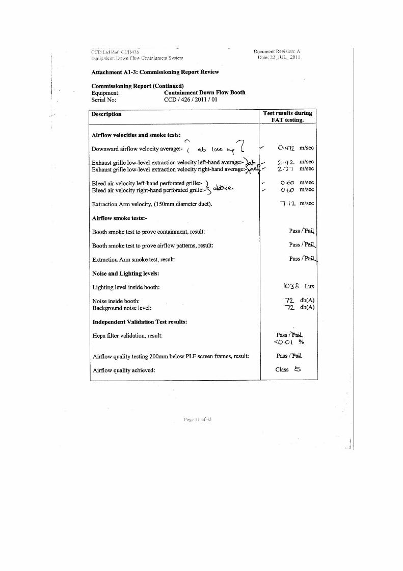
averaging capability. Face velocity of capture hoods was measured using a thermal anemometer. Information for expected flow rates are gathered from the original 2011 Commissioning Data.
Readings on page 11 give indicative acceptable airflow readings at less than readings taken from HSE
258. These are- down flow velocity average (taken at 1000mm high) 0.47m/s –exhaust grill at low
level 2.40m/s- and bleed air velocity (taken 200mm below laminar flow ceiling membrane) 0.60m/s.
These values gave a basis for air tests carried out. Further tests were carried out to test
containment. These were testing airflow towards the back wall and taken in a vertical plane. These
were justified using smoke testing.
1.4 EQUIPMENT USED
Rotating Vane Anemometer
Pitot tube with Electronic Differential Pressure Meter
Hot Wire Anemometer
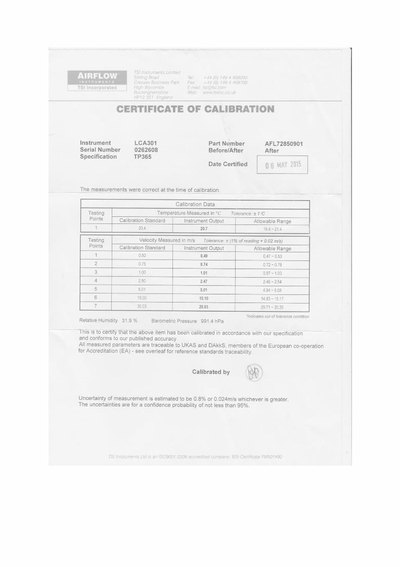
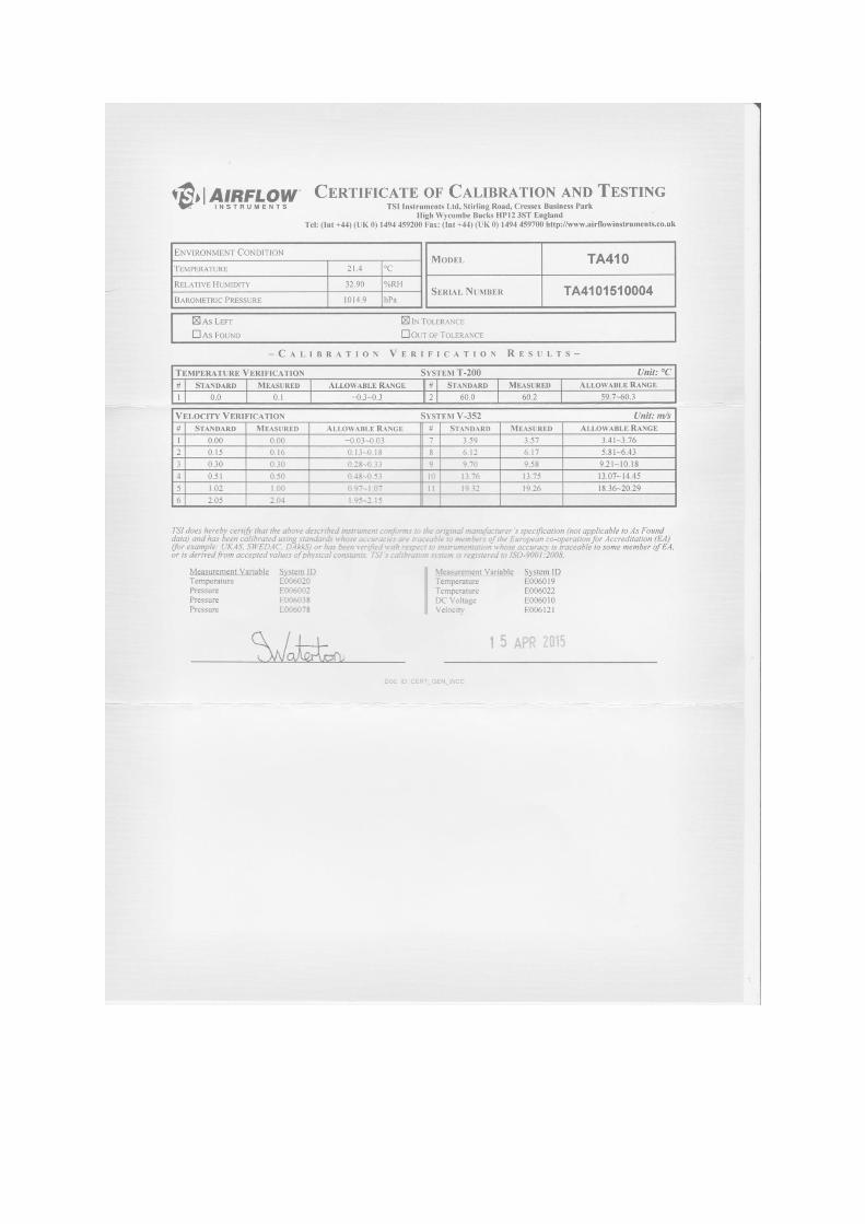
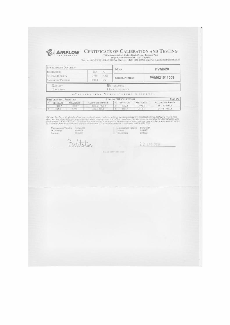
Calibration Certification with equipment details is included at the end of the report.
2. SUMMARY
Both the booth and captor hood achieve a
SATISFACTORY level of control.
A Risk Assessment needs to be prepared which includes
the regularity of filter changes and adverse interaction if
hood is used within the booth.
The booth needs to be marked up with a safe working
zone definition.
Facilitate qualitative light testing of booth for dust
containment control when process is operative.
Program for LEV retest at least within the next fourteen
months.
Keep LEV records available with existing Logbook.
3.1 SYSTEM DESCRIPTION
UNIT DESCRIPTION Downflow Containment Booth System Manufactured by Concept Containment Designs Ltd. West Yorkshire LS25 4BU, tel. 0113 286 6498
SUNIT REFERENCE 2015/1
LOCATION AGT 2 Building
DATA FAN 2no Centrifugal fans on the same shaft .Belt driven. MOTOR ABB Motors M2AA112M-4 serial 3GAA112101-ADE rpm 1425 kW 4.0 FILTERS Prefilters- Pleated Panel G4 Secondary Filters Rigid Pocket F8 Tertiary filters HEPA H13
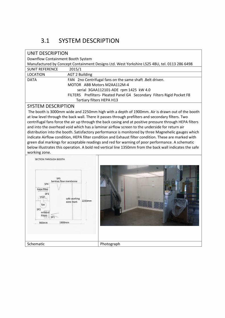
SYSTEM DESCRIPTION The booth is 3000mm wide and 2250mm high with a depth of 1900mm. Air is drawn out of the booth at low level through the back wall. There it passes through prefilters and secondary filters. Two centrifugal fans force the air up through the back casing and at positive pressure through HEPA filters and into the overhead void which has a laminar airflow screen to the underside for return air distribution into the booth. Satisfactory performance is monitored by three Magnehelic gauges which indicate Airflow condition, HEPA filter condition and Exhaust filter condition. These are marked with green dial markings for acceptable readings and red for warning of poor performance. A schematic below illustrates this operation. A bold red vertical line 1350mm from the back wall indicates the safe working zone.
Schematic Photograph
Observations and Comments RISK ASSESSMENT – No Risk Assessment or Method Statements for work processes have yet been formulated. ELECTRICAL CONTROLS and ISOLATION are in the far recess behind the booth due to their original desired location. FANS- Dual fans are powered by the same motor. One has baffle with adjustment. Fans are in good condition and with correct rotation. FILTERS-A complete set of filters have been fitted and all seals were found to be in good condition. Hepa challenge and validation was not deemed necessary in this situation. FILTER CLEANING- There is no mechanism for cleaning so replacement interval needs consideration. Dust is likely to be valuable so Johnson Matthey are to deal with disposal. EXPECTED PROCESS- Decanting and weighing of silver dust EXPECTED CONTAMINANT- Silver dust. WEL to be confirmed. GENERAL CONDITION- Some minor damage to laminar flow screen otherwise good. METERING- Flow metering is clear and easily visible. DISCHARGE-is recycle through the booth only. EXPLOSION-No provision is made for explosion release.
UNIT DESCRIPTION Extraction Arm Manufactured by Concept Containment Designs Ltd. West Yorkshire LS25 4BU, tel. 0113 286 6498
UNIT REFERENCE 2015/2
LOCATION AGT 2 Building
DATA FAN Centrifugal fan with direct drive. ESTA RG 200 Serial 11001460 MOTOR Aperetebau GmbH & Co 1kW 2000m3/hr FILTERS Filter Rigid Pocket F8 Secondary filter HEPA H13
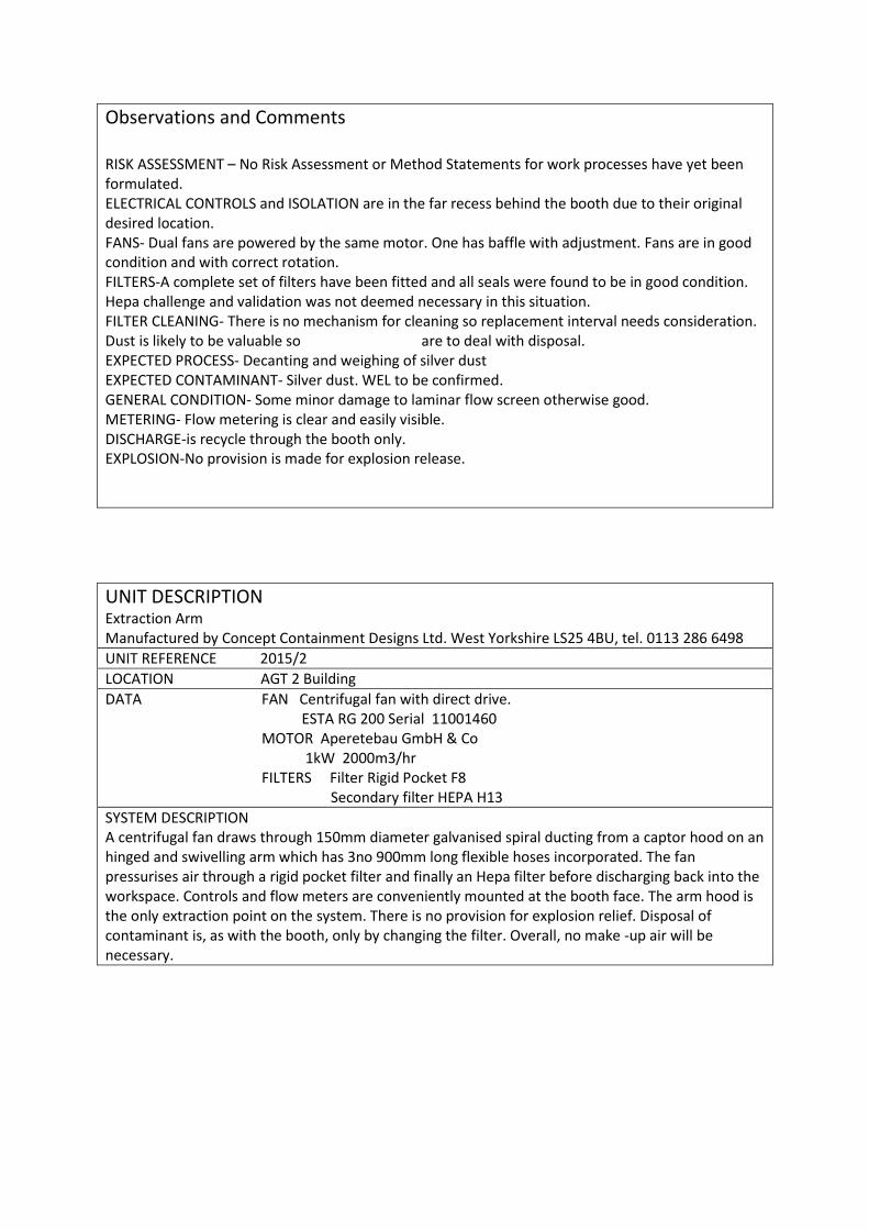
SYSTEM DESCRIPTION A centrifugal fan draws through 150mm diameter galvanised spiral ducting from a captor hood on an hinged and swivelling arm which has 3no 900mm long flexible hoses incorporated. The fan pressurises air through a rigid pocket filter and finally an Hepa filter before discharging back into the workspace. Controls and flow meters are conveniently mounted at the booth face. The arm hood is the only extraction point on the system. There is no provision for explosion relief. Disposal of contaminant is, as with the booth, only by changing the filter. Overall, no make -up air will be necessary.
Schematic Photographs
OBSERVATIONS AND COMMENTS The fan is in good condition and the rotation correct. RISK ASSESSMENT – No Risk Assessment or Method Statements for work processes have yet been formulated. When they are, if the arm is to be used within the booth, consideration needs to be given to any adverse interaction and the effect on airflows within the booth or into the hood. ELECTRICAL CONTROLS and ISOLATION are accessible at the front of the booth. FANS- The fan is in good condition and with correct rotation. FILTERS-A complete set of filters have been fitted and all seals were found to be in good condition. Hepa challenge and validation was not deemed necessary in this situation. FILTER CLEANING- There is no mechanism for cleaning so replacement interval needs consideration. Dust is likely to be valuable so Johnson Matthey is to deal with disposal. EXPECTED PROCESS- Decanting and weighing of silver dust EXPECTED CONTAMINANT- Silver dust. WEL to be confirmed. GENERAL CONDITION- is good. METERING- Flow metering is clear and easily visible. DISCHARGE-is recycle into workspace only. EXPLOSION-No provision is made for explosion release.
3.2 TESTING AND RESULTS
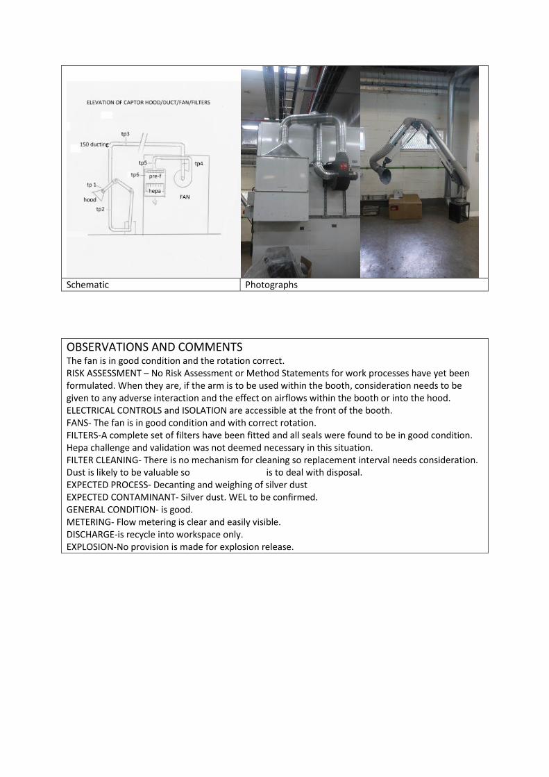
Containment Booth Airflow Readings (Averages)
Ref Plane of readings Dimensions mm
Reading m/s
Expected value m/s
PASS/FAIL
1 Horizontal- 200mm below laminar flow ceiling
3000 x 1550 0.63 0.6 Pass
2 Vertical at exhaust grill 450 x 2700 3.08 2.4 Pass
3 Vertical at 1350 from back wall 2250 x 3000 0.00 0.4 hsg Fail
4 Vertical at 950 from back wall 2250 x 3000 0.37 0.4 hsg OK
5 Horizontal at 1000 high 3000 x 1550 0.52 0.5 Pass
Test Point
Location of Static Reading SP Static Pressure in Pa
Sp 1 Before pre-filter -1
Sp 2 Before fan -98
Sp 3 After fan before Hepa +284
Sp 4 After Hepa +54
SP 5 In void over booth +62
Calculations of differential pressures Dial Pa
across pre/sec filters 97 100 Pass
across HEPA filters 230 220 Pass
Qualitative Assessment by Smoke Release Smoke testing for inflow to booth at 1350mm from back wall and in the region of breathing zone proved inconclusive. Smoke testing for inflow to booth at 950mm from back wall and in the region of breathing zone justifies adequate airflow. Smoke testing for downflow to exhaust filters also justifies adequate airflow. Any Tyndale Lamp testing awaits process initiation.
CAPTOR HOOD ON ARM AIRFLOW AVERAGE READINGS Ref Description Dimension/
Diameter mm
Face Velocity m/s
Duct Velocity m/s
Pa Static Pressure
Indicative Expected Velocity m/s
Pass/ Fail
Hood face 300x260 5.3 1-2.5
120 from hood 1.0 Pass
Tp1 Behind hood 150 12.9
Tp2 In duct 150 14.7 15.0 Pass
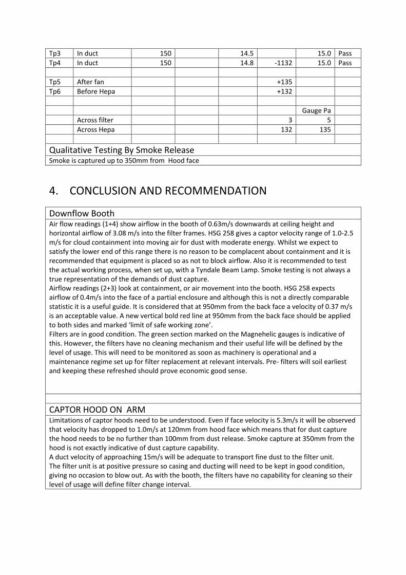
Tp3 In duct 150 14.5 15.0 Pass
Tp4 In duct 150 14.8 -1132 15.0 Pass
Tp5 After fan +135
Tp6 Before Hepa +132
Gauge Pa
Across filter 3 5
Across Hepa 132 135
Qualitative Testing By Smoke Release Smoke is captured up to 350mm from Hood face
4. CONCLUSION AND RECOMMENDATION
Downflow Booth Air flow readings (1+4) show airflow in the booth of 0.63m/s downwards at ceiling height and horizontal airflow of 3.08 m/s into the filter frames. HSG 258 gives a captor velocity range of 1.0-2.5 m/s for cloud containment into moving air for dust with moderate energy. Whilst we expect to satisfy the lower end of this range there is no reason to be complacent about containment and it is recommended that equipment is placed so as not to block airflow. Also it is recommended to test the actual working process, when set up, with a Tyndale Beam Lamp. Smoke testing is not always a true representation of the demands of dust capture. Airflow readings (2+3) look at containment, or air movement into the booth. HSG 258 expects airflow of 0.4m/s into the face of a partial enclosure and although this is not a directly comparable statistic it is a useful guide. It is considered that at 950mm from the back face a velocity of 0.37 m/s is an acceptable value. A new vertical bold red line at 950mm from the back face should be applied to both sides and marked ‘limit of safe working zone’. Filters are in good condition. The green section marked on the Magnehelic gauges is indicative of this. However, the filters have no cleaning mechanism and their useful life will be defined by the level of usage. This will need to be monitored as soon as machinery is operational and a maintenance regime set up for filter replacement at relevant intervals. Pre- filters will soil earliest and keeping these refreshed should prove economic good sense.
CAPTOR HOOD ON ARM Limitations of captor hoods need to be understood. Even if face velocity is 5.3m/s it will be observed that velocity has dropped to 1.0m/s at 120mm from hood face which means that for dust capture the hood needs to be no further than 100mm from dust release. Smoke capture at 350mm from the hood is not exactly indicative of dust capture capability. A duct velocity of approaching 15m/s will be adequate to transport fine dust to the filter unit. The filter unit is at positive pressure so casing and ducting will need to be kept in good condition, giving no occasion to blow out. As with the booth, the filters have no capability for cleaning so their level of usage will define filter change interval.
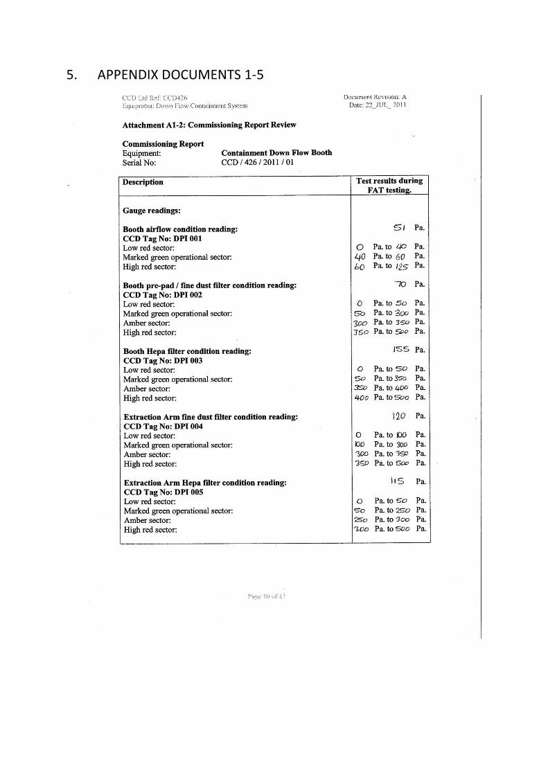
5. APPENDIX DOCUMENTS 1-5