local exhaust & ventilation thorough examination & test · local exhaust & ventilation...
TRANSCRIPT
Ducting Express Services Ltd
Trade House
7 Claymill Road
Thurmaston
LE4 9JJ
Local Exhaust & Ventilation
Thorough Examination & Test
Company Name:
Cadbury Sixth Form College
Downland Close
Kings Norton
Birmingham B38 8QT
LEV Report – DEXP22012014BH
Last Test Date K/N
Test Date 22-01-2014
Next Test Date 22-01-2015
British Occupational Hygiene Society Certified P601
Richard Debenham Certificate No 050711/008
Brodrick Hill Certificate No 20130321-28141-1723
Page 1 of 8
REPORT CONTENTS PAGE 1
SUMMARY OF LEV PAGE 2
SCOPE OF WORK PAGE 3 to 6
MAINTENANCE SCHEDULE EXAMPLE PAGE 7
PRIORITY ACTION LEVELS PAGE 8
LEV REPORTS, TABLES, DIAGRAMS & PHOTOS
ROUTINE EXAMINATION & TEST WAS CARRIED OUT BY:
Brodrick Hill Signed:
Date: 22nd
January 2014
British Occupational Hygiene Society Certified P601
Richard Debenham Certificate No 050711/008
Brodrick Hill Certificate No 20130321-28141-1723
Page 2 of 8
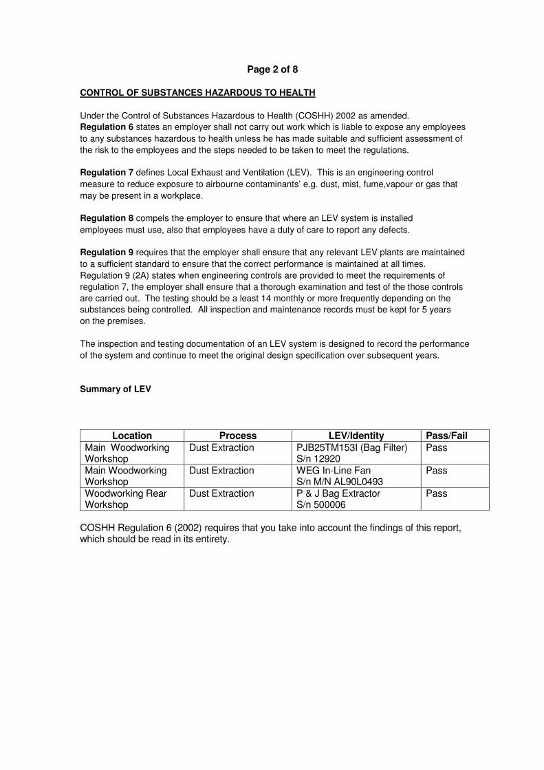
CONTROL OF SUBSTANCES HAZARDOUS TO HEALTH
Under the Control of Substances Hazardous to Health (COSHH) 2002 as amended.
Regulation 6 states an employer shall not carry out work which is liable to expose any employees
to any substances hazardous to health unless he has made suitable and sufficient assessment of
the risk to the employees and the steps needed to be taken to meet the regulations.
Regulation 7 defines Local Exhaust and Ventilation (LEV). This is an engineering control
measure to reduce exposure to airbourne contaminants’ e.g. dust, mist, fume,vapour or gas that
may be present in a workplace.
Regulation 8 compels the employer to ensure that where an LEV system is installed
employees must use, also that employees have a duty of care to report any defects.
Regulation 9 requires that the employer shall ensure that any relevant LEV plants are maintained
to a sufficient standard to ensure that the correct performance is maintained at all times.
Regulation 9 (2A) states when engineering controls are provided to meet the requirements of
regulation 7, the employer shall ensure that a thorough examination and test of the those controls
are carried out. The testing should be a least 14 monthly or more frequently depending on the
substances being controlled. All inspection and maintenance records must be kept for 5 years
on the premises.
The inspection and testing documentation of an LEV system is designed to record the performance
of the system and continue to meet the original design specification over subsequent years.
Summary of LEV
Location Process LEV/Identity Pass/Fail
Main Woodworking Workshop
Dust Extraction PJB25TM153I (Bag Filter) S/n 12920
Pass
Main Woodworking Workshop
Dust Extraction WEG In-Line Fan S/n M/N AL90L0493
Pass
Woodworking Rear Workshop
Dust Extraction P & J Bag Extractor S/n 500006
Pass
COSHH Regulation 6 (2002) requires that you take into account the findings of this report, which should be read in its entirety.
Page 3 of 8
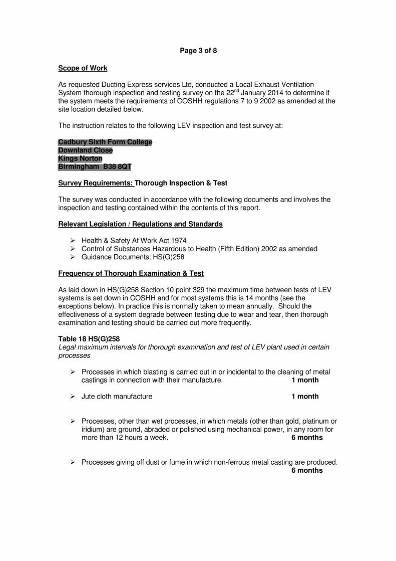
Scope of Work As requested Ducting Express services Ltd, conducted a Local Exhaust Ventilation System thorough inspection and testing survey on the 22nd January 2014 to determine if the system meets the requirements of COSHH regulations 7 to 9 2002 as amended at the site location detailed below. The instruction relates to the following LEV inspection and test survey at: Cadbury Sixth Form College Downland Close Kings Norton Birmingham B38 8QT Survey Requirements: Thorough Inspection & Test The survey was conducted in accordance with the following documents and involves the inspection and testing contained within the contents of this report. Relevant Legislation / Regulations and Standards
� Health & Safety At Work Act 1974 � Control of Substances Hazardous to Health (Fifth Edition) 2002 as amended � Guidance Documents: HS(G)258
Frequency of Thorough Examination & Test As laid down in HS(G)258 Section 10 point 329 the maximum time between tests of LEV systems is set down in COSHH and for most systems this is 14 months (see the exceptions below). In practice this is normally taken to mean annually. Should the effectiveness of a system degrade between testing due to wear and tear, then thorough examination and testing should be carried out more frequently. Table 18 HS(G)258 Legal maximum intervals for thorough examination and test of LEV plant used in certain processes
� Processes in which blasting is carried out in or incidental to the cleaning of metal castings in connection with their manufacture. 1 month
� Jute cloth manufacture 1 month
� Processes, other than wet processes, in which metals (other than gold, platinum or iridium) are ground, abraded or polished using mechanical power, in any room for more than 12 hours a week. 6 months
� Processes giving off dust or fume in which non-ferrous metal casting are produced. 6 months
Page 4 of 8
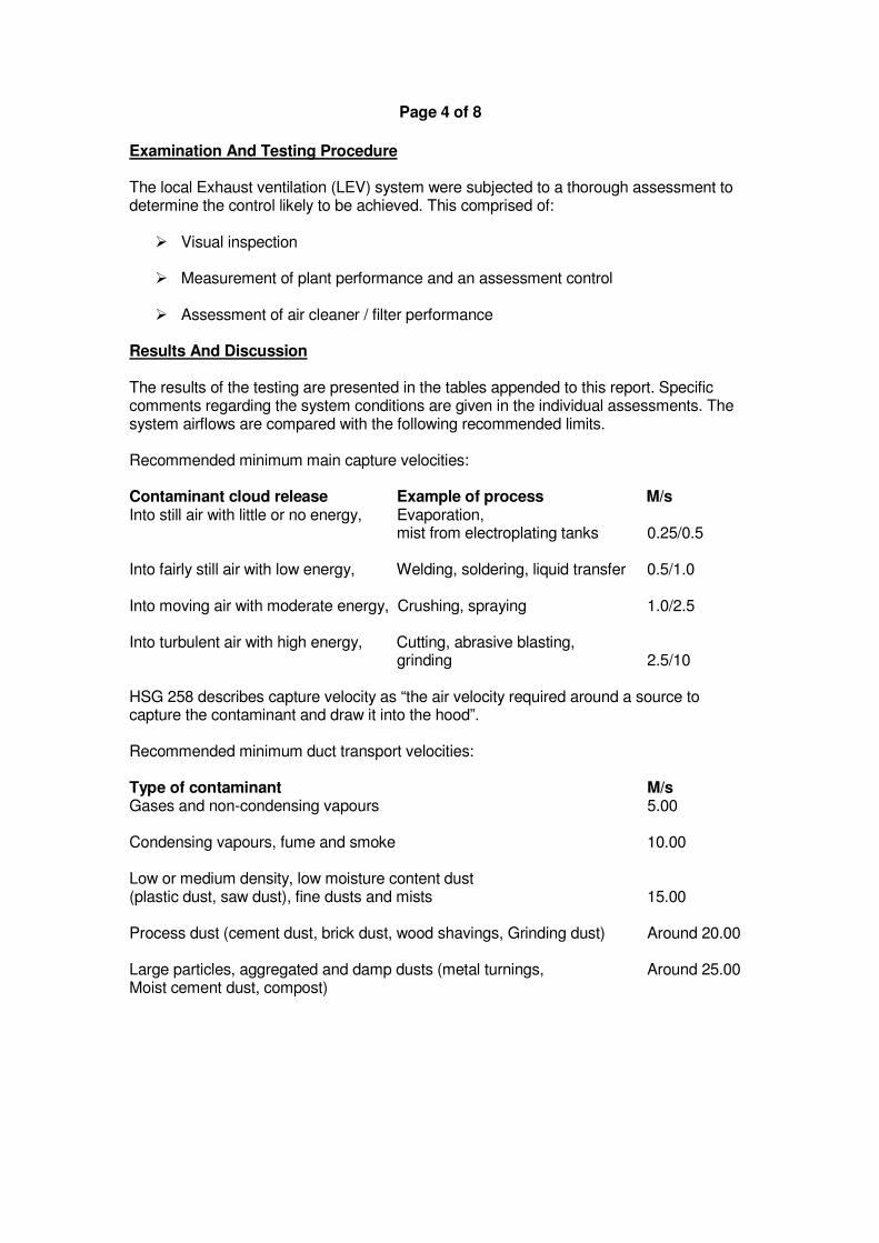
Examination And Testing Procedure The local Exhaust ventilation (LEV) system were subjected to a thorough assessment to determine the control likely to be achieved. This comprised of:
� Visual inspection � Measurement of plant performance and an assessment control � Assessment of air cleaner / filter performance
Results And Discussion The results of the testing are presented in the tables appended to this report. Specific comments regarding the system conditions are given in the individual assessments. The system airflows are compared with the following recommended limits. Recommended minimum main capture velocities: Contaminant cloud release Example of process M/s Into still air with little or no energy, Evaporation,
mist from electroplating tanks 0.25/0.5 Into fairly still air with low energy, Welding, soldering, liquid transfer 0.5/1.0 Into moving air with moderate energy, Crushing, spraying 1.0/2.5 Into turbulent air with high energy, Cutting, abrasive blasting,
grinding 2.5/10
HSG 258 describes capture velocity as “the air velocity required around a source to capture the contaminant and draw it into the hood”. Recommended minimum duct transport velocities: Type of contaminant M/s Gases and non-condensing vapours 5.00 Condensing vapours, fume and smoke 10.00 Low or medium density, low moisture content dust (plastic dust, saw dust), fine dusts and mists 15.00 Process dust (cement dust, brick dust, wood shavings, Grinding dust) Around 20.00 Large particles, aggregated and damp dusts (metal turnings, Around 25.00 Moist cement dust, compost)
Page 5 of 8
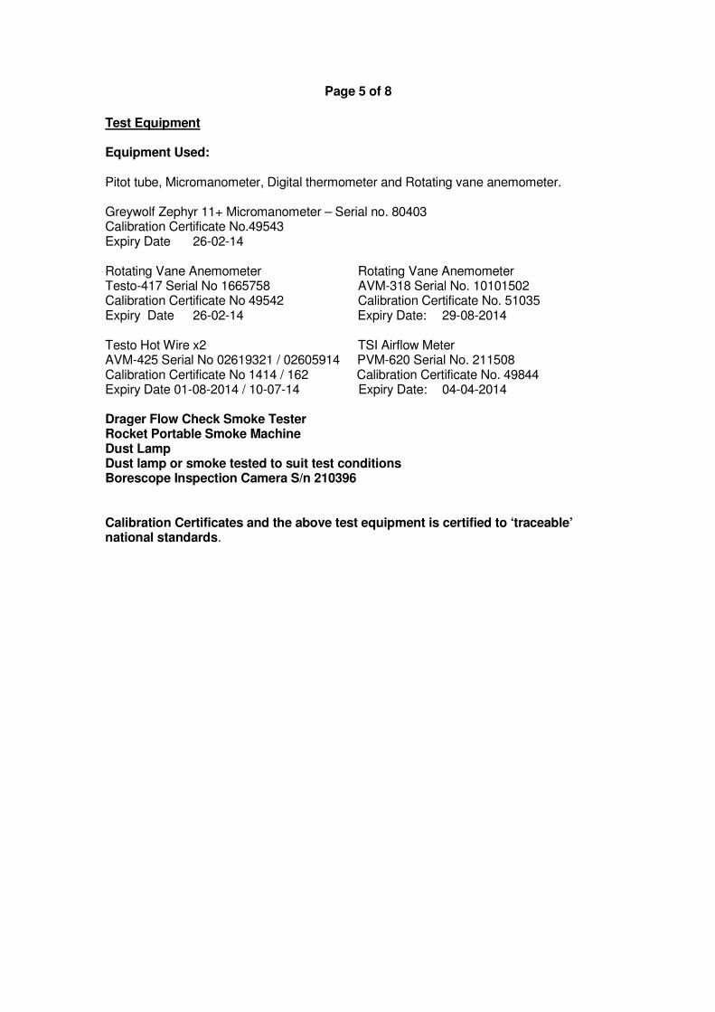
Test Equipment Equipment Used: Pitot tube, Micromanometer, Digital thermometer and Rotating vane anemometer. Greywolf Zephyr 11+ Micromanometer – Serial no. 80403 Calibration Certificate No.49543 Expiry Date 26-02-14 Rotating Vane Anemometer Rotating Vane Anemometer Testo-417 Serial No 1665758 AVM-318 Serial No. 10101502 Calibration Certificate No 49542 Calibration Certificate No. 51035 Expiry Date 26-02-14 Expiry Date: 29-08-2014 Testo Hot Wire x2 TSI Airflow Meter AVM-425 Serial No 02619321 / 02605914 PVM-620 Serial No. 211508 Calibration Certificate No 1414 / 162 Calibration Certificate No. 49844 Expiry Date 01-08-2014 / 10-07-14 Expiry Date: 04-04-2014 Drager Flow Check Smoke Tester Rocket Portable Smoke Machine Dust Lamp Dust lamp or smoke tested to suit test conditions Borescope Inspection Camera S/n 210396 Calibration Certificates and the above test equipment is certified to ‘traceable’ national standards.
Page 6 of 8
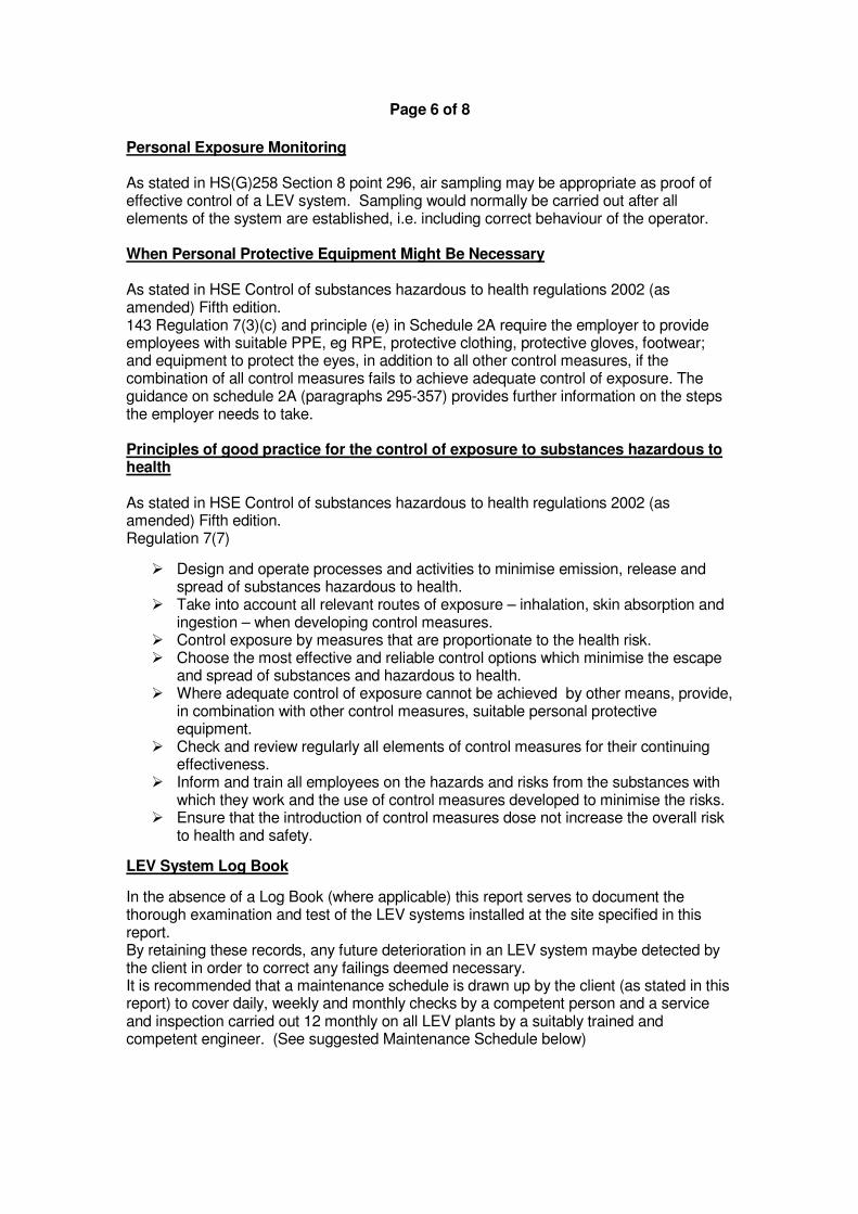
Personal Exposure Monitoring As stated in HS(G)258 Section 8 point 296, air sampling may be appropriate as proof of effective control of a LEV system. Sampling would normally be carried out after all elements of the system are established, i.e. including correct behaviour of the operator. When Personal Protective Equipment Might Be Necessary As stated in HSE Control of substances hazardous to health regulations 2002 (as amended) Fifth edition. 143 Regulation 7(3)(c) and principle (e) in Schedule 2A require the employer to provide employees with suitable PPE, eg RPE, protective clothing, protective gloves, footwear; and equipment to protect the eyes, in addition to all other control measures, if the combination of all control measures fails to achieve adequate control of exposure. The guidance on schedule 2A (paragraphs 295-357) provides further information on the steps the employer needs to take. Principles of good practice for the control of exposure to substances hazardous to health As stated in HSE Control of substances hazardous to health regulations 2002 (as amended) Fifth edition. Regulation 7(7)
� Design and operate processes and activities to minimise emission, release and spread of substances hazardous to health.
� Take into account all relevant routes of exposure – inhalation, skin absorption and ingestion – when developing control measures.
� Control exposure by measures that are proportionate to the health risk. � Choose the most effective and reliable control options which minimise the escape
and spread of substances and hazardous to health. � Where adequate control of exposure cannot be achieved by other means, provide,
in combination with other control measures, suitable personal protective equipment.
� Check and review regularly all elements of control measures for their continuing effectiveness.
� Inform and train all employees on the hazards and risks from the substances with which they work and the use of control measures developed to minimise the risks.
� Ensure that the introduction of control measures dose not increase the overall risk to health and safety.
LEV System Log Book
In the absence of a Log Book (where applicable) this report serves to document the thorough examination and test of the LEV systems installed at the site specified in this report. By retaining these records, any future deterioration in an LEV system maybe detected by the client in order to correct any failings deemed necessary. It is recommended that a maintenance schedule is drawn up by the client (as stated in this report) to cover daily, weekly and monthly checks by a competent person and a service and inspection carried out 12 monthly on all LEV plants by a suitably trained and competent engineer. (See suggested Maintenance Schedule below)
Page 7 of 8
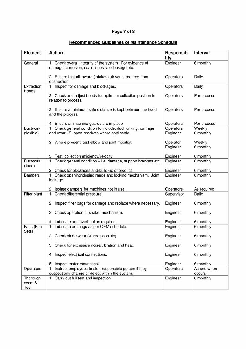
Recommended Guidelines of Maintenance Schedule
Element Action Responsibility
Interval
General 1. Check overall integrity of the system. For evidence of damage, corrosion, seals, substrate leakage etc. 2. Ensure that all inward (intakes) air vents are free from obstruction.
Engineer Operators
6 monthly Daily
Extraction Hoods
1. Inspect for damage and blockages. 2. Check and adjust hoods for optimum collection position in relation to process. 3. Ensure a minimum safe distance is kept between the hood and the process. 4. Ensure all machine guards are in place.
Operators Operators Operators Operators
Daily Per process Per process Per process
Ductwork (flexible)
1. Check general condition to include; duct kinking, damage and wear. Support brackets where applicable. 2. Where present, test elbow and joint mobility. 3. Test collection efficiency/velocity
Operators Engineer Operator Engineer Engineer
Weekly 6 monthly Weekly 6 monthly 6 monthly
Ductwork (fixed)
1. Check general condition – i.e. damage, support brackets etc. 2. Check for blockages and/build-up of product.
Engineer Engineer
6 monthly 6 monthly
Dampers 1. Check opening/closing range and locking mechanism. Joint leakage. 2. Isolate dampers for machines not in use.
Engineer Operators
6 monthly As required
Filter plant 1. Check differential pressure. 2. Inspect filter bags for damage and replace where necessary. 3. Check operation of shaker mechanism. 4. Lubricate and overhaul as required.
Supervisor Engineer Engineer Engineer
Daily 6 monthly 6 monthly 6 monthly
Fans (Fan Sets)
1. Lubricate bearings as per OEM schedule. 2. Check blade wear (where possible). 3. Check for excessive noise/vibration and heat. 4. Inspect electrical connections. 5. Inspect motor mountings.
Engineer Engineer Engineer Engineer Engineer
6 monthly 6 monthly 6 monthly 6 monthly 6 monthly
Operators 1. Instruct employees to alert responsible person if they suspect any change or defect within the system.
Operators As and when occurs
Thorough exam & Test
1. Carry out full test and inspection Engineer 6 monthly
Page 8 of 8
Priority Action HSE guidance recommends examiners label each hood with a test record. Alternatively, the test record label could be placed near by, for instance, close to the system on/off switch. It should be clearly visible to the supervisor and operatives. HSE guidance recommends that a red ‘Failed’ label should be put on any hoods (or system) that has failed, to warn supervisors and operators directly and explicitly. This could be done by the examiner with the agreement from the employer (client). Or a label could be issued to the employers responsible person. With the label should come a short ‘emergency’ written report containing a clear description of what is wrong and a list of practical remedial actions. Corrective action that may be required is ranked on a scale of 1 – 3. Priority Action: 1. High – immediate action
2. Medium – Highly recommended 3. Routine or ongoing i.e. planned maintenance and training
The corrective use of the LEV plant to include correct positioning of capture hoods should be monitored and enforced by senior staff. Any recommendations for the improvement of LEV systems are by guidance only and there may be alternatives to improve a LEV systems efficiency that may not be stated within this report. The practicability of these recommendations within this report should be investigated by the client and a competent designer and installer.

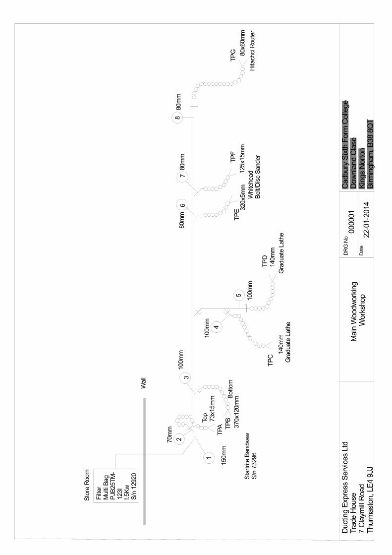
Plant Location/System ID: LEV1 Main Woodworking Workshop. Make and model: PJB25TM153I Fan/motor: 1.5Kw 2855RPM Serial No.: 12920 Final emission discharge: Internal to atmosphere - filtered. Contaminants under control: Hard/soft wood, MDF Total inhalable dust WEL of 5mg/m3/8hrTWA Total respirable dust WEL of 5mg/m3/8hrTWA Purpose of Plant: Extraction of dust particulate from the machining of hard/soft woods, and MDF. Conditions: Plant in normal operation.
Temperature: 20°C Fan Type Direct drive centrifugal (clockwise rotation) Plant Inspection Status Filter Details Good Faulty Particulars of Repairs Required Unit Exterior � Filter Media � Elements Secondary Filter Seals � Cleaning System Shaker System � Waste Disposal � Rotary Valve Screw conveyors Motor � FanSet / Impeller � Explosion Panels Duct Work � Electrical Wiring � Manometers � Requires Magnehelic gauge.
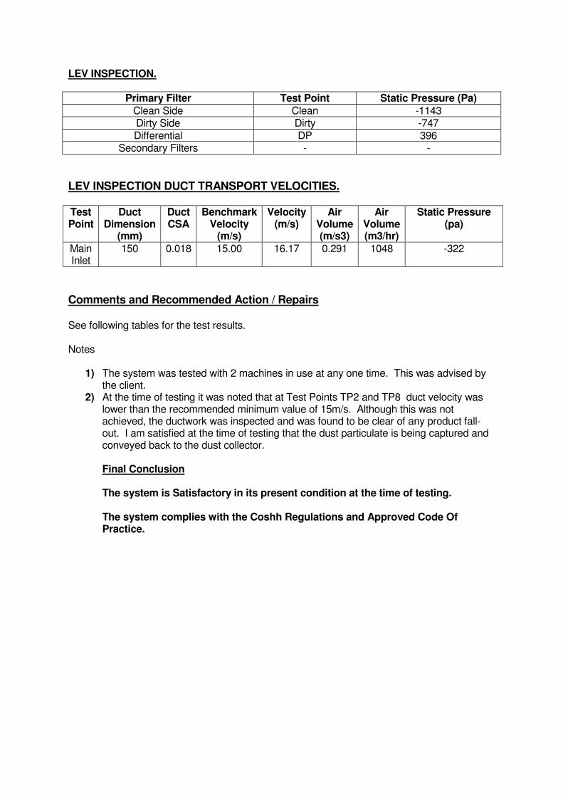
LEV INSPECTION.
Primary Filter Test Point Static Pressure (Pa)
Clean Side Clean -1143 Dirty Side Dirty -747 Differential DP 396
Secondary Filters - -
LEV INSPECTION DUCT TRANSPORT VELOCITIES. Test Point
Duct Dimension
(mm)
Duct CSA
Benchmark Velocity
(m/s)
Velocity (m/s)
Air Volume (m/s3)
Air Volume (m3/hr)
Static Pressure (pa)
Main Inlet
150 0.018 15.00 16.17 0.291 1048 -322
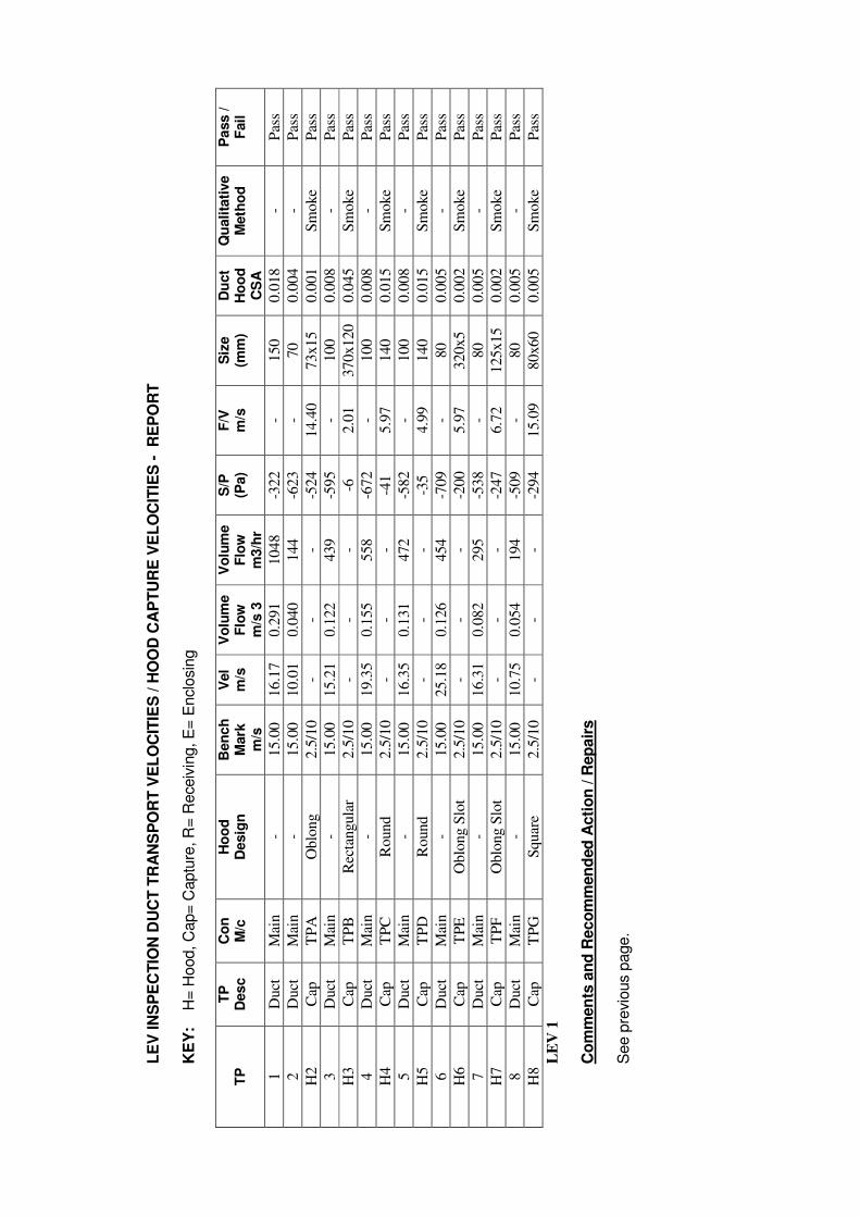
Comments and Recommended Action / Repairs See following tables for the test results. Notes
1) The system was tested with 2 machines in use at any one time. This was advised by the client.
2) At the time of testing it was noted that at Test Points TP2 and TP8 duct velocity was lower than the recommended minimum value of 15m/s. Although this was not achieved, the ductwork was inspected and was found to be clear of any product fall-out. I am satisfied at the time of testing that the dust particulate is being captured and conveyed back to the dust collector. Final Conclusion The system is Satisfactory in its present condition at the time of testing. The system complies with the Coshh Regulations and Approved Code Of Practice.
LE
V IN
SP
EC
TIO
N D
UC
T T
RA
NS
PO
RT
VE
LO
CIT
IES
/ H
OO
D C
AP
TU
RE
VE
LO
CIT
IES
- R
EP
OR
T
KE
Y:
H
= H
ood, C
ap=
Captu
re, R
= R
eceiv
ing, E
= E
nclo
sin
g
TP
T
P
Des
c
Co
n
M/c
H
oo
d
Desig
n
Ben
ch
M
ark
m
/s
Vel
m/s
V
olu
me
Flo
w
m/s
3
Vo
lum
e
Flo
w
m3/h
r
S/P
(P
a)
F/V
m
/s
Siz
e
(mm
) D
uct
Ho
od
C
SA
Qu
ali
tati
ve
M
eth
od
P
ass /
F
ail
1
Duct
M
ain
- 15.0
0
16.1
7
0.2
91
1048
-322
-
150
0.0
18
- P
ass
2
Duct
M
ain
- 15.0
0
10.0
1
0.0
40
144
-623
-
70
0.0
04
- P
ass
H2
Cap
T
PA
O
blo
ng
2.5
/10
- -
- -5
24
14.4
0
73x15
0.0
01
Sm
oke
P
ass
3
Duct
M
ain
- 15.0
0
15.2
1
0.1
22
439
-595
-
100
0.0
08
- P
ass
H3
Cap
T
PB
R
ecta
ngula
r 2.5
/10
- -
- -6
2.0
1
370x120
0.0
45
Sm
oke
P
ass
4
Duct
M
ain
- 15.0
0
19.3
5
0.1
55
558
-672
-
100
0.0
08
- P
ass
H4
Cap
T
PC
R
ound
2.5
/10
- -
- -4
1
5.9
7
140
0.0
15
Sm
oke
Pas
s
5
Duct
M
ain
- 15.0
0
16.3
5
0.1
31
472
-582
-
100
0.0
08
- P
ass
H5
Cap
T
PD
R
ound
2.5
/10
- -
- -3
5
4.9
9
140
0.0
15
Sm
oke
Pas
s
6
Duct
M
ain
- 15.0
0
25.1
8
0.1
26
454
-709
-
80
0.0
05
- P
ass
H6
Cap
T
PE
O
blo
ng S
lot
2.5
/10
- -
- -2
00
5.9
7
320x5
0.0
02
Sm
oke
Pas
s
7
Duct
M
ain
- 15.0
0
16.3
1
0.0
82
295
-538
-
80
0.0
05
- P
ass
H7
Cap
T
PF
O
blo
ng S
lot
2.5
/10
- -
- -2
47
6.7
2
125x15
0.0
02
Sm
oke
Pas
s
8
Duct
M
ain
- 15.0
0
10.7
5
0.0
54
194
-509
-
80
0.0
05
- P
ass
H8
Cap
T
PG
S
quar
e 2.5
/10
- -
- -2
94
15.0
9
80x60
0.0
05
Sm
oke
Pas
s
LE
V 1
Co
mm
en
ts a
nd
Reco
mm
en
ded
Acti
on
/ R
ep
air
s
See p
revio
us p
age.
DRG No
Date
Cadbury Sixth Form College
Downland Clase
Kings Norton
Birmingham, B38 8QT
000001
22-01-2014
Main Woodworking
Workshop
Ducting Express Services Ltd
Trade House
7 Claymill Road
Thurmaston, LE4 9JJ
1
23
4
5
67
8
TPG 80x60mm
Hitachci Router
80mm
80mm
80mm
125x15mm
320x5mm
Whitehead
Belt/Disc Sander
Graduate Lathe
Graduate Lathe
140mm
140mm100mm
100mm
370x120mm
150mm
70mm
100mm
Startrite Bandsaw
S/n 73296
Top
Bottom
73x15mm
TPA TPB
TPC
TPD
TPE
TPF
Wall
Store Room
Filter
Multi Bag
PJB25TM-
123I
!.5Kw
S/n 12920
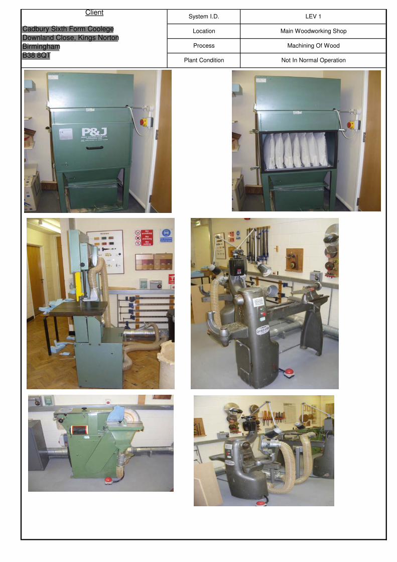
Machining Of Wood
Plant Condition Not In Normal Operation
ClientSystem I.D. LEV 1
Cadbury Sixth Form Coolege
Downland Close, Kings Norton
Birmingham
B38 8QT
Location Main Woodworking Shop
Process
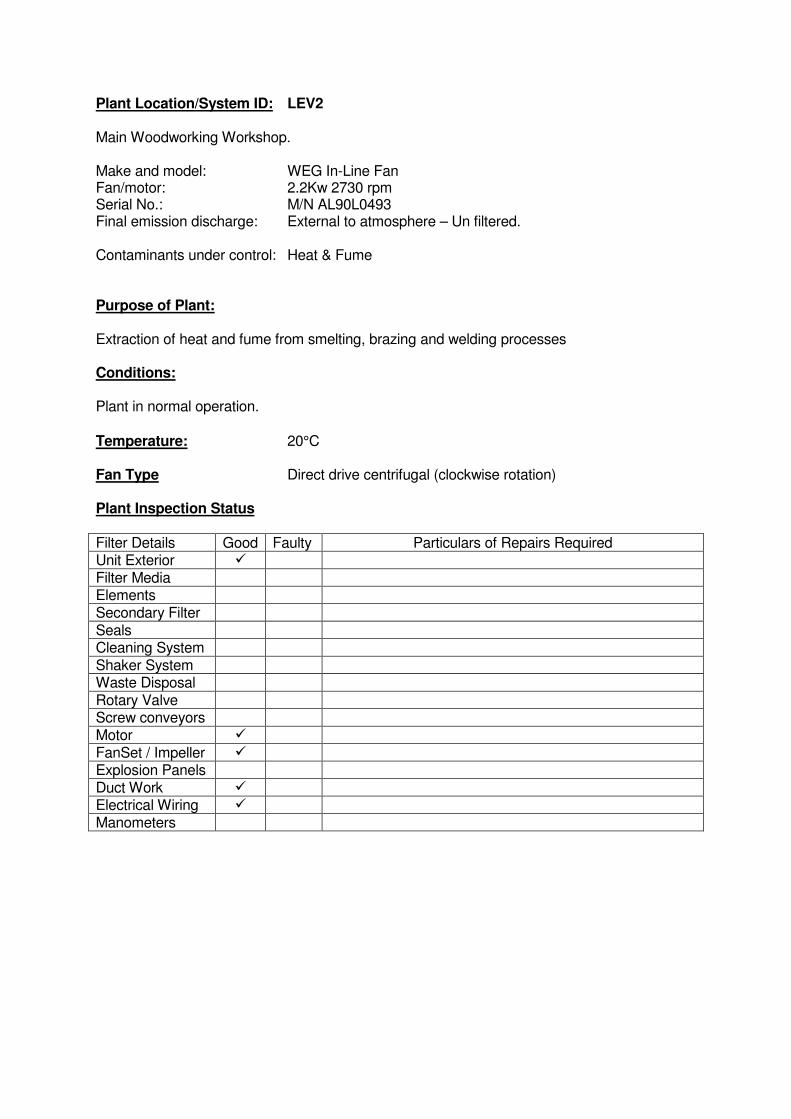
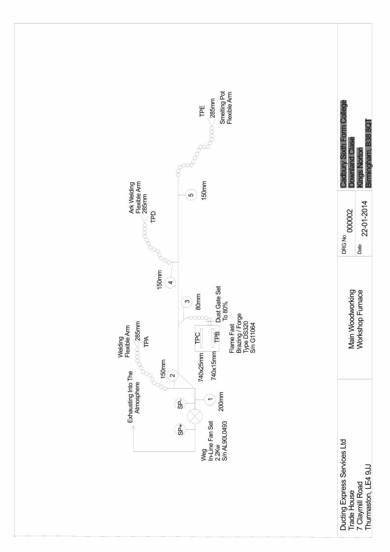
Plant Location/System ID: LEV2 Main Woodworking Workshop. Make and model: WEG In-Line Fan Fan/motor: 2.2Kw 2730 rpm Serial No.: M/N AL90L0493 Final emission discharge: External to atmosphere – Un filtered. Contaminants under control: Heat & Fume Purpose of Plant: Extraction of heat and fume from smelting, brazing and welding processes Conditions: Plant in normal operation.
Temperature: 20°C Fan Type Direct drive centrifugal (clockwise rotation) Plant Inspection Status Filter Details Good Faulty Particulars of Repairs Required Unit Exterior � Filter Media Elements Secondary Filter Seals Cleaning System Shaker System Waste Disposal Rotary Valve Screw conveyors Motor � FanSet / Impeller � Explosion Panels Duct Work � Electrical Wiring � Manometers
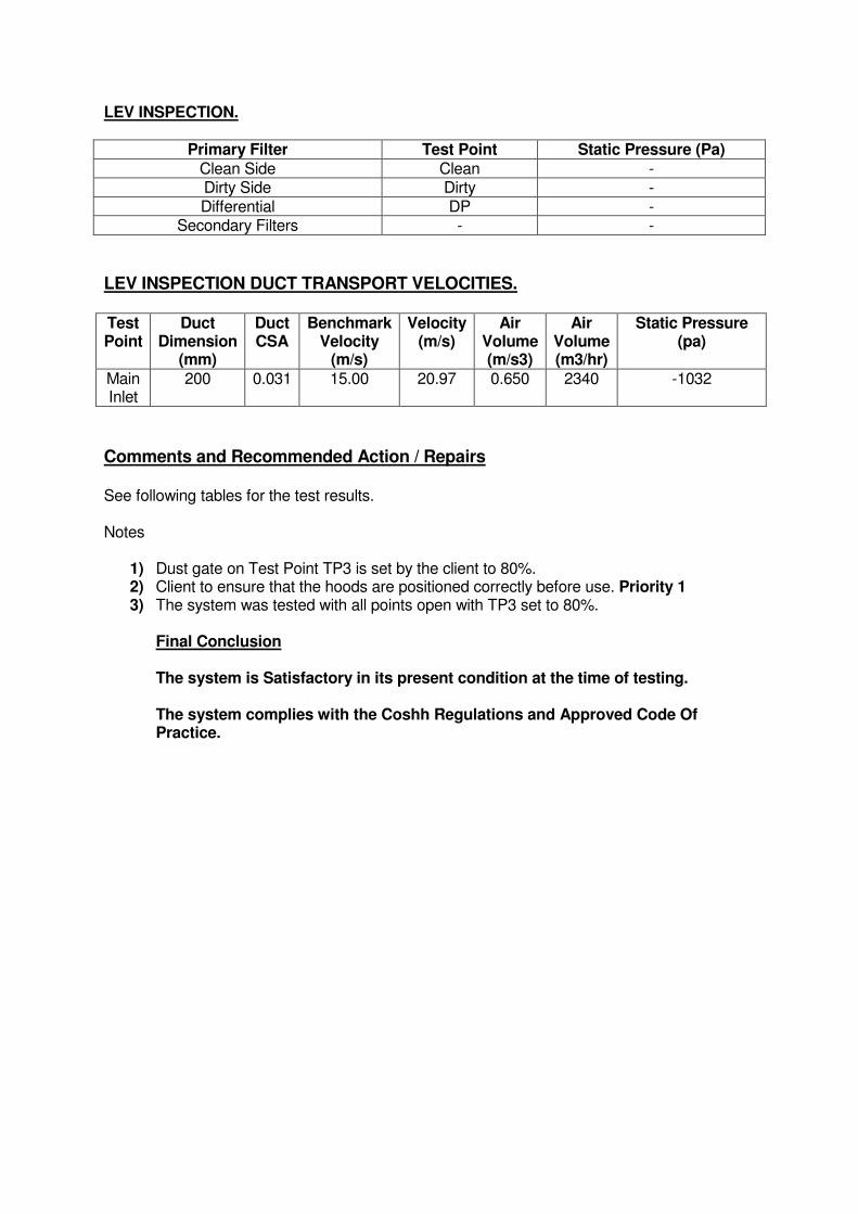
LEV INSPECTION.
Primary Filter Test Point Static Pressure (Pa)
Clean Side Clean - Dirty Side Dirty - Differential DP -
Secondary Filters - -
LEV INSPECTION DUCT TRANSPORT VELOCITIES. Test Point
Duct Dimension
(mm)
Duct CSA
Benchmark Velocity
(m/s)
Velocity (m/s)
Air Volume (m/s3)
Air Volume (m3/hr)
Static Pressure (pa)
Main Inlet
200 0.031 15.00 20.97 0.650 2340 -1032
Comments and Recommended Action / Repairs See following tables for the test results. Notes
1) Dust gate on Test Point TP3 is set by the client to 80%. 2) Client to ensure that the hoods are positioned correctly before use. Priority 1 3) The system was tested with all points open with TP3 set to 80%.
Final Conclusion The system is Satisfactory in its present condition at the time of testing. The system complies with the Coshh Regulations and Approved Code Of Practice.
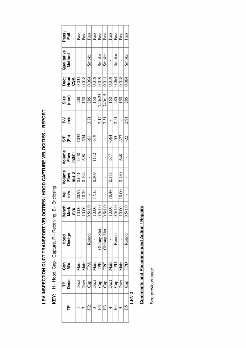
LE
V IN
SP
EC
TIO
N D
UC
T T
RA
NS
PO
RT
VE
LO
CIT
IES
/ H
OO
D C
AP
TU
RE
VE
LO
CIT
IES
- R
EP
OR
T
KE
Y:
H
= H
ood, C
ap=
Captu
re, R
= R
eceiv
ing, E
= E
nclo
sin
g
TP
T
P
Des
c
Co
n
M/c
H
oo
d
Desig
n
Ben
ch
M
ark
m
/s
Vel
m/s
V
olu
me
Flo
w
m/s
3
Vo
lum
e
Flo
w
m3/h
r
S/P
(P
a)
F/V
m
/s
Siz
e
(mm
) D
uct
Ho
od
C
SA
Qu
ali
tati
ve
M
eth
od
P
ass /
F
ail
1
Duct
M
ain
- 10.0
0
20.9
7
0.6
51
2340
-1032
-
200
0.0
31
- P
ass
2
Duct
M
ain
- 10.0
0
10.7
9
0.1
94
698
-554
-
150
0.0
18
- P
ass
H2
Cap
T
PA
R
ound
0.5
/1.0
-
- -
-61
3.7
1
285
0.0
64
Sm
oke
P
ass
3
Duct
M
ain
- 10.0
0
17.1
5
0.3
09
1112
-519
-
150
0.0
18
- P
ass
H3
Cap
T
PB
O
blo
ng S
lot
0.5
/1.0
-
- -
- 7.1
7
740x25
0.0
19
Sm
oke
P
ass
H3
Cap
T
PC
O
blo
ng S
lot
0.5
/1.0
-
- -
- 7.5
1
740x15
0.0
11
Sm
oke
Pas
s
4
Duct
M
ain
- 10.0
0
10.4
4
0.1
88
677
-364
-
150
0.0
18
- P
ass
H4
Cap
T
PD
R
ound
0.5
/1.0
-
- -
-53
2.5
1
285
0.0
64
Sm
oke
Pas
s
5
Duct
M
ain
- 10.0
0
10.0
0
0.1
80
648
-327
-
150
0.0
18
- P
ass
H5
Cap
T
PD
R
ound
0.5
/1.0
-
- -
-22
2.9
1
285
0.0
64
Sm
oke
Pas
s
LE
V 2
Co
mm
en
ts a
nd
Reco
mm
en
ded
Acti
on
/ R
ep
air
s
See p
revio
us p
age.
DRG No
Date
Cadbury Sixth Form College
Downland Clase
Kings Norton
Birmingham, B38 8QT
22-01-2014
Main Woodworking
Workshop Furnace
Ducting Express Services Ltd
Trade House
7 Claymill Road
Thurmaston, LE4 9JJ
000002
285mm
5
150mm
150mm
80mm
4
3
285mm
TPD
TPE
Smelting Pot
Flexible Arm
Ark Welding
Flexible Arm
Welding
Flexible Arm
285mm
TPA
2150mm
1
200mm
SP-
SP+
TPC
TPB
740x25mm
740x15mm
Dust Gate Set
To 80%
Exhausting Into The
Atmosphere
Weg
In-Line Fan Set
2.2Kw
S/n AL90L0493
Flame Fast
Brazing / Forge
Type DS320
S/n G11064
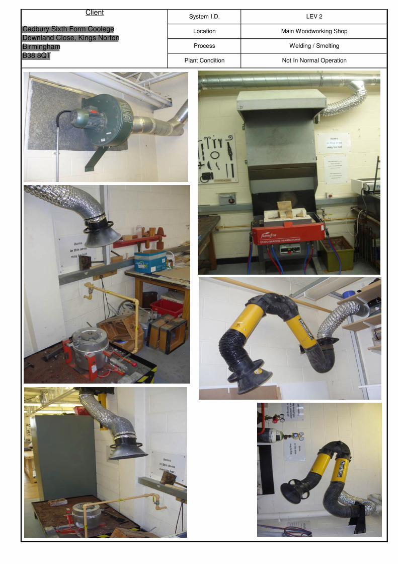
Process Welding / Smelting
Plant Condition Not In Normal Operation
ClientSystem I.D. LEV 2
Cadbury Sixth Form Coolege
Downland Close, Kings Norton
Birmingham
B38 8QT
Location Main Woodworking Shop
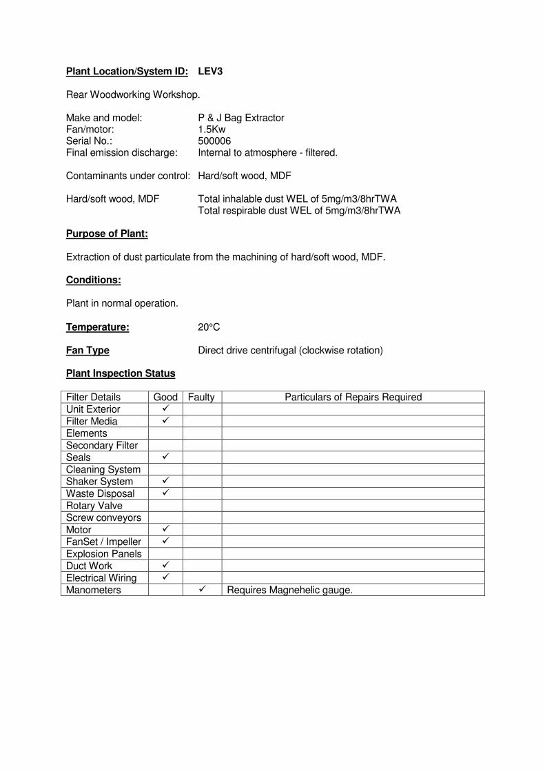
Plant Location/System ID: LEV3 Rear Woodworking Workshop. Make and model: P & J Bag Extractor Fan/motor: 1.5Kw Serial No.: 500006 Final emission discharge: Internal to atmosphere - filtered. Contaminants under control: Hard/soft wood, MDF Hard/soft wood, MDF Total inhalable dust WEL of 5mg/m3/8hrTWA Total respirable dust WEL of 5mg/m3/8hrTWA Purpose of Plant: Extraction of dust particulate from the machining of hard/soft wood, MDF. Conditions: Plant in normal operation.
Temperature: 20°C Fan Type Direct drive centrifugal (clockwise rotation) Plant Inspection Status Filter Details Good Faulty Particulars of Repairs Required Unit Exterior � Filter Media � Elements Secondary Filter Seals � Cleaning System Shaker System � Waste Disposal � Rotary Valve Screw conveyors Motor � FanSet / Impeller � Explosion Panels Duct Work � Electrical Wiring � Manometers � Requires Magnehelic gauge.
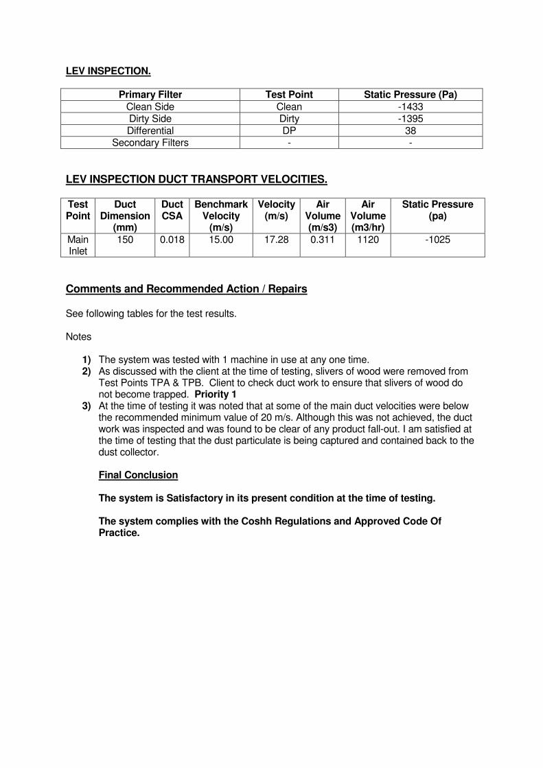
LEV INSPECTION.
Primary Filter Test Point Static Pressure (Pa)
Clean Side Clean -1433 Dirty Side Dirty -1395 Differential DP 38
Secondary Filters - -
LEV INSPECTION DUCT TRANSPORT VELOCITIES. Test Point
Duct Dimension
(mm)
Duct CSA
Benchmark Velocity
(m/s)
Velocity (m/s)
Air Volume (m/s3)
Air Volume (m3/hr)
Static Pressure (pa)
Main Inlet
150 0.018 15.00 17.28 0.311 1120 -1025
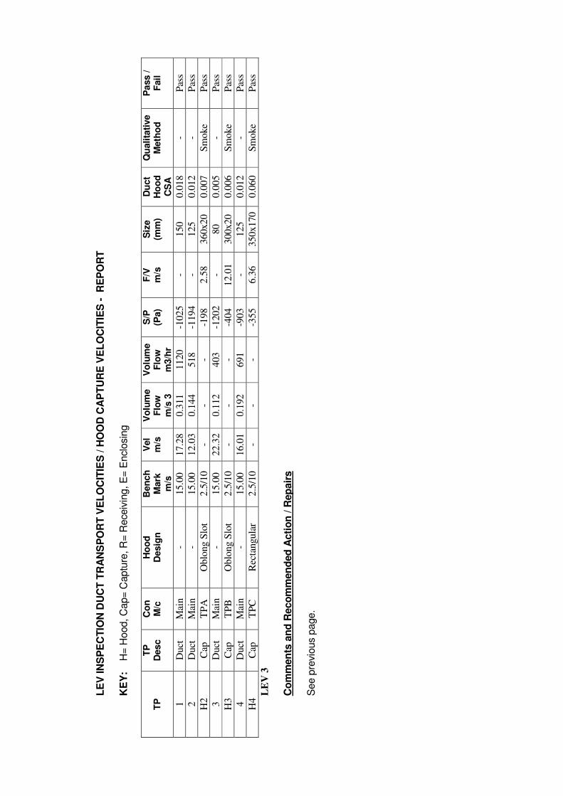
Comments and Recommended Action / Repairs See following tables for the test results. Notes
1) The system was tested with 1 machine in use at any one time. 2) As discussed with the client at the time of testing, slivers of wood were removed from
Test Points TPA & TPB. Client to check duct work to ensure that slivers of wood do not become trapped. Priority 1
3) At the time of testing it was noted that at some of the main duct velocities were below the recommended minimum value of 20 m/s. Although this was not achieved, the duct work was inspected and was found to be clear of any product fall-out. I am satisfied at the time of testing that the dust particulate is being captured and contained back to the dust collector. Final Conclusion The system is Satisfactory in its present condition at the time of testing. The system complies with the Coshh Regulations and Approved Code Of Practice.
LE
V IN
SP
EC
TIO
N D
UC
T T
RA
NS
PO
RT
VE
LO
CIT
IES
/ H
OO
D C
AP
TU
RE
VE
LO
CIT
IES
- R
EP
OR
T
KE
Y:
H
= H
ood, C
ap=
Captu
re, R
= R
eceiv
ing, E
= E
nclo
sin
g
TP
T
P
Des
c
Co
n
M/c
H
oo
d
Desig
n
Ben
ch
M
ark
m
/s
Vel
m/s
V
olu
me
Flo
w
m/s
3
Vo
lum
e
Flo
w
m3/h
r
S/P
(P
a)
F/V
m
/s
Siz
e
(mm
) D
uct
Ho
od
C
SA
Qu
ali
tati
ve
M
eth
od
P
ass /
F
ail
1
Duct
M
ain
- 15.0
0
17.2
8
0.3
11
1120
-1025
-
150
0.0
18
- P
ass
2
Duct
M
ain
- 15.0
0
12.0
3
0.1
44
518
-1194
-
125
0.0
12
- P
ass
H2
Cap
T
PA
O
blo
ng S
lot
2.5
/10
- -
- -1
98
2.5
8
360x20
0.0
07
Sm
oke
P
ass
3
Duct
M
ain
- 15.0
0
22.3
2
0.1
12
403
-1202
-
80
0.0
05
- P
ass
H3
Cap
T
PB
O
blo
ng S
lot
2.5
/10
- -
- -4
04
12.0
1
300x20
0.0
06
Sm
oke
P
ass
4
Duct
M
ain
- 15.0
0
16.0
1
0.1
92
691
-903
-
125
0.0
12
- P
ass
H4
Cap
T
PC
R
ecta
ngula
r 2.5
/10
- -
- -3
55
6.3
6
350x170
0.0
60
Sm
oke
Pas
s
LE
V 3
Co
mm
en
ts a
nd
Reco
mm
en
ded
Acti
on
/ R
ep
air
s
See p
revio
us p
age.
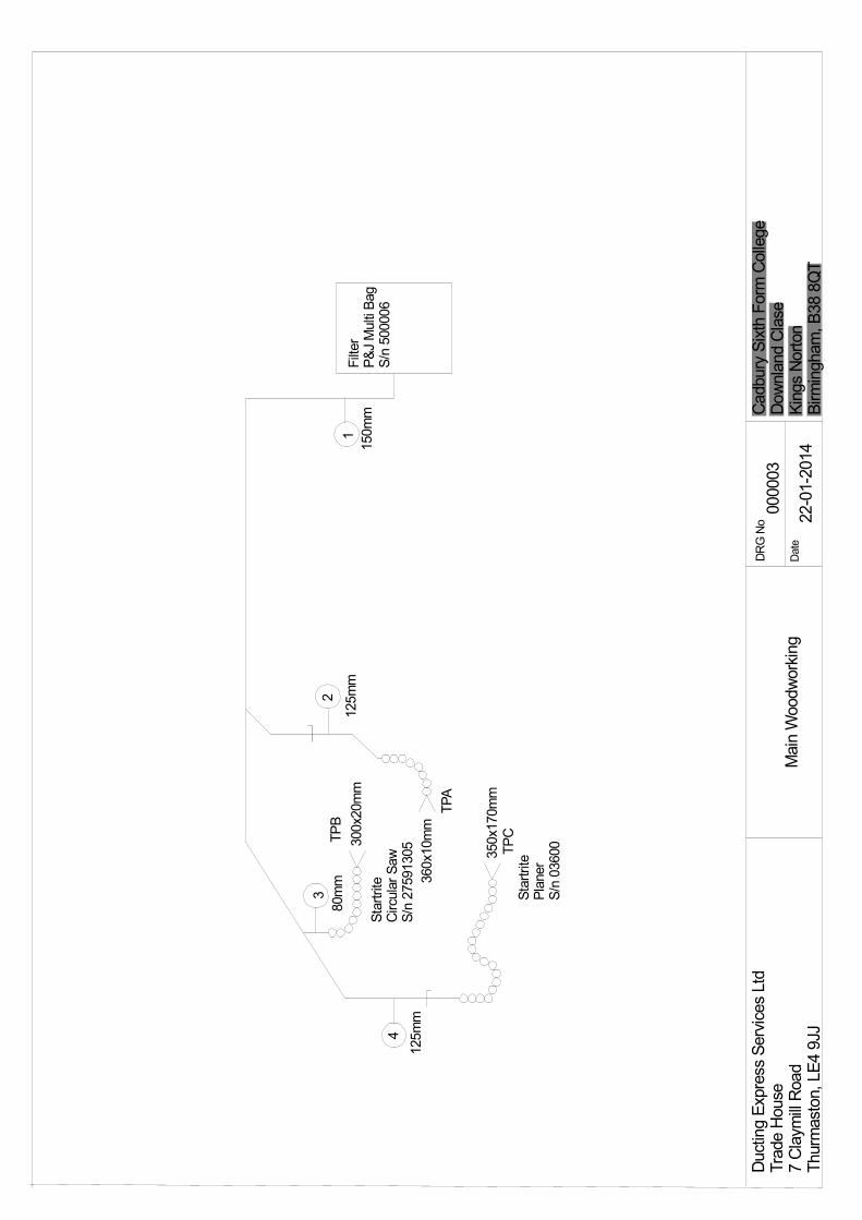
DRG No
Date
Cadbury Sixth Form College
Downland Clase
Kings Norton
Birmingham, B38 8QT
22-01-2014
Main Woodworking
Ducting Express Services Ltd
Trade House
7 Claymill Road
Thurmaston, LE4 9JJ
000003
1
23
4
125mm
80mm
125mm
150mm
Startrite
Circular Saw
S/n 27591305300x20mm
TPB
360x10mm
TPA
350x170mm
TPC
Startrite
Planer
S/n 03600
Filter
P&J Multi Bag
S/n 500006
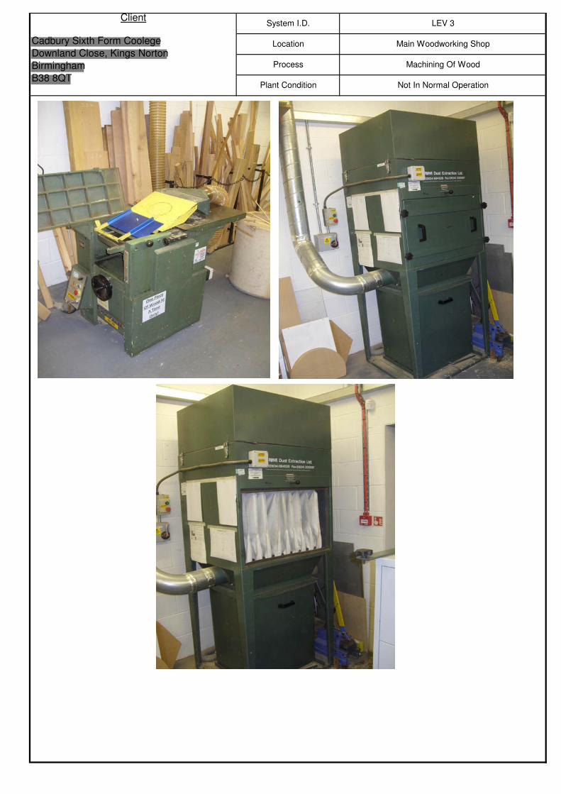
Plant Condition Not In Normal Operation
ClientSystem I.D. LEV 3
Cadbury Sixth Form Coolege
Downland Close, Kings Norton
Birmingham
B38 8QT
Location Main Woodworking Shop
Process Machining Of Wood