locomotive design centre rdso - aitdaitd.net.in/pdf/7/10. locomotive design centre - rdso.pdf ·...
TRANSCRIPT

LOCOMOTIVE DESIGN CENTRE RDSO
WELCOME
TO

SOFTWARE USED
UNIGRAPHICS(NX) CAD
TEAM CENTER PDM
ANSYS FEM
MSC Nastran Fatigue Analysis
CAD- COPMUTER AIDED DESIGN
PDM- PRODUCT DATA MANAGEMENT


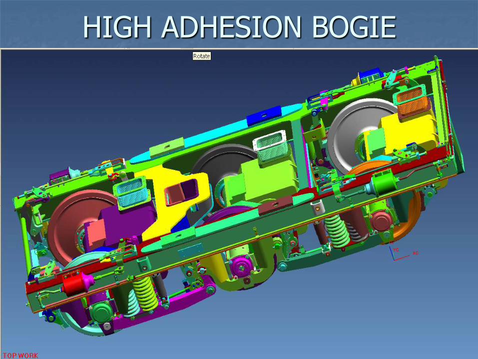
HIGH ADHESION BOGIE


LOCOMOTIVE UNDERFRAME

DETAIL OF UNDERFRAME

WMD3D PLATFORM

LOCO UNDERFRAME WITH SUB ASSEMBLIES
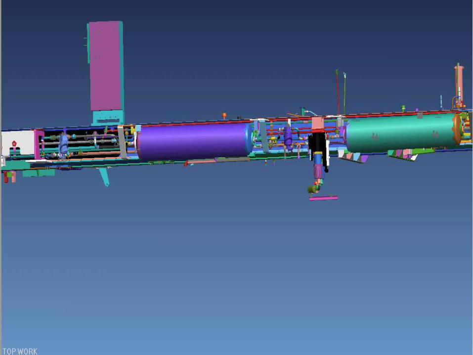

PIPING & ROUTING

HOOD OVER ENGINE ASSEMBLY

LOCOMOTIVE CAB

CONTROL CABINET

ELECTRICAL CABINET

LOCOMOTIVE SHORT HOOD

CONTROL STAND

DIGITAL LOCO DIESEL

PROJECT/LOCO DESIGN COMPLETED WDM3D END CAB

PROJECT/LOCO DESIGN Completed
BG Bangladesh 2600hp BG Sri Lanka 2300 hp
MG Malaysia 2300hp MG Vietnam 1300hp

SUDAN/MAYANMAR LOCO
ANGOLA LOCO
HOTEL LOAD LOCO

SUDAN/MAYANMAR LOCO

COACH BOGIE DESIGN
AND
AIR SUSPENSION
- TOPICS ON BOGIE DESIGN
- MODES OF COACH BODY OSCILLATION.
- DESIGN OF BOGIE COMPONENTS.
- DESIGN OF SUSPENSION ELEMENTS.
- VEHICLE DYNAMICS SIMULATIONS.
- FIELD TRIALS.
- TOPICS ON AIR SUSPENSION
- NEED FOR AIR SUSPENSION.
- DETAILS OF AIR SUSPENSION.
- CONTROL EQUIPMENTS.
- DESIGN.
- ADVANTAGE.

DESIGN REQUIREMENT
GAUGE
SPEED
AXLE LOAD
MAX MOVING DIMENSION
MIN CURVE NEGOTIATION
ANY OTHER SPECIFIC REQUIREMENT…..

BOGIE DESIGN
VEHICLE MOTION QUANTITIES.
DEGREES OF FREEDOM.
VIBRATION EXCITATION.
SUSPENSION DESIGN.
SAFETY AGAINST DERAILMENT.
RIDING QUALITY. RESONANCE AND HUNTING
VEHICLE DYNAMICS SIMULATIONS. OSCILLATION TRIALS.


VEHICLE DYNAMIC SIMULATIONS
(MATHEMATICAL MODELING)
SOFTWARE PACKAGES
NUCARS ADAMS RAIL
VEHICLE RELATED
TRACK RELATED
RAIL/WHEEL CONTACT
INPUT VEHICLE
DYNAMICS
SOFTWARE
PACKAGE
OUTPUT
FORCES
DISPLACEMENT
VELOCITY
ACCELERATION
VEHICLE MODEL VEHICLE OUT PUT
•NUCARS - NEW UNTRIED CAR ANALYSIS REGIEM SIMULATIONS
•ADAMS RAIL – AUTOMATIC DYNAMIC ANALYSIS OF MECHANICAL SYSTEMS
ADVANTAGES • MODEL OF ANY RAILWAY VEHICLE CAN BE DEVELOPED.
•ASSESMENT OF VEHICLE RIDING AND STABILITY.
•PARAMETRIC OPTIMISATION OF SUSPENSION
•HAZARD FREE
•COST EFFECTIVE


AIR SUSPENSION
FOR
COMFORT
SAFETY
AND
RELIABILITY WITH
ECONOMY

ADVANTAGES OF AIR
SUSPENSION
- MAINTAINS SAME HEIGHT BY LOAD SENSING.
- ADEQUATE BOGIE CLEARENCES.
- LOW VIBRATIONS AND NOISE.
- LOW SPACE REQUIREMENTS.
- ALMOST SAME NATURAL FREQUENCY UNDER EMPTY AND LOADED CONDITIONS.
- BETTER RIDING QUALITY.
- REDUCED LATERAL FORCES.
- INCRESE IN SPEED POTENTIAL.
- LOW MAINTENANCE.

BOGIE SYSTEM ON WDG2, WDP1 & WDP2 LOCOMOTIVES

BOGIE DESIGN CRITERIA
Axle load
Speed Potential
Adhesion requirement
Curve negotiability
Bogie dynamics based on the given track parameters and wheel profile L/V ratio
Lateral force
Lateral and Vertical Acceleration
Ride Index
Bogie Swing

BOGIE DESIGN CRITERIA (Contd.)
Kinematics of bogie linkage
Bogie Clearances
Weight Transfer
Axle load equalization
Braking
Rail bending Stiffness

BOGIE CLASSIFICATION
Based on Suspension single stage)
Flexi-Coil (Two stage)
High adhesion (Two stage)
Based on Wheel/Axle mechanism Rigid
Radical – Power Steering
Self Steering

Dynamics of Vehicle
Wheel set Dynamics
Bogie Dynamics
Carbody Dynamics

BOGIE COMPONENT DESCRIPTION
BOGIE FRAME
Integral cast Bogie frame
Fabricated
Cast
SUSPENSION
Single Stage Steel helical coil spring
Rubber

BOGIE COMPONENT DESCRIPTION
Two Stage With bolster
Without bolster
Hydraulic dampers Primary (Vertical ,Lateral, yaw damper)
Secondary (Vertical & Lateral,Yaw Damper
Traction motor damper – used in case of fully suspended traction motor

BOGIE COMPONENT DESCRIPTION
Traction Arrangement Primary
Pedestal (Horn)
Guidelink or Primary traction rod
Secondary traction Chaffing plate
Traction bar
Secondary traction rod
Pivot Pin Assembly Rigid Pivot
Takes vertical carbody load
Floating Pivot Used in Two-stage suspension
BOGIE COMPONENT DESCRIPTION
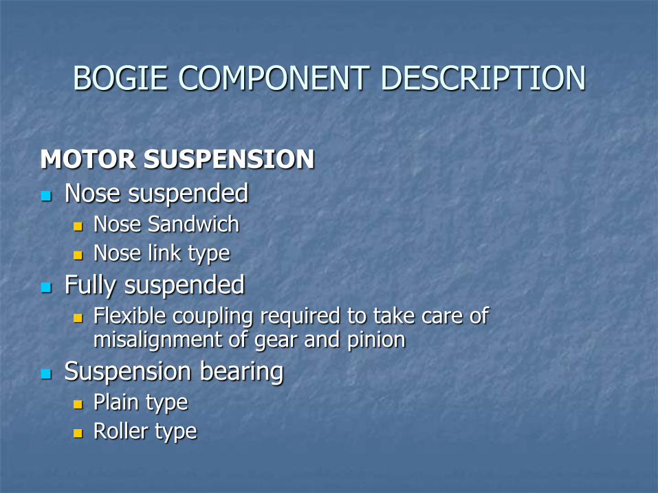
MOTOR SUSPENSION
Nose suspended Nose Sandwich
Nose link type
Fully suspended Flexible coupling required to take care of
misalignment of gear and pinion
Suspension bearing Plain type
Roller type

BOGIE COMPONENT DESCRIPTION
WHEEL, AXLE & BEARING JOURNAL
Wheel
Curved web
Straight web (for disc brake fitment)
Axle
Solid axle
Hollow Axle
Bearing
Cylindrical Roller
Taper Roller

BOGIE COMPONENT DESCRIPTION
BRAKE RIGGING
Conventional Single or double clasped
Cast iron brake block
Composite brake block
TBU
Disc type (for high speed operation)
Parking brake In-built in TBU
Separately designed by SAB WABCO

BOGIE COMPONENT DESCRIPTION
Sanding Arrangement
Bogie mounted
Carbody mounted
Safety Component
Horn stay plate
Lifting connection
Lateral & vertical stop component
Liners ; Horn, pivot and wearing surface
Safety strap

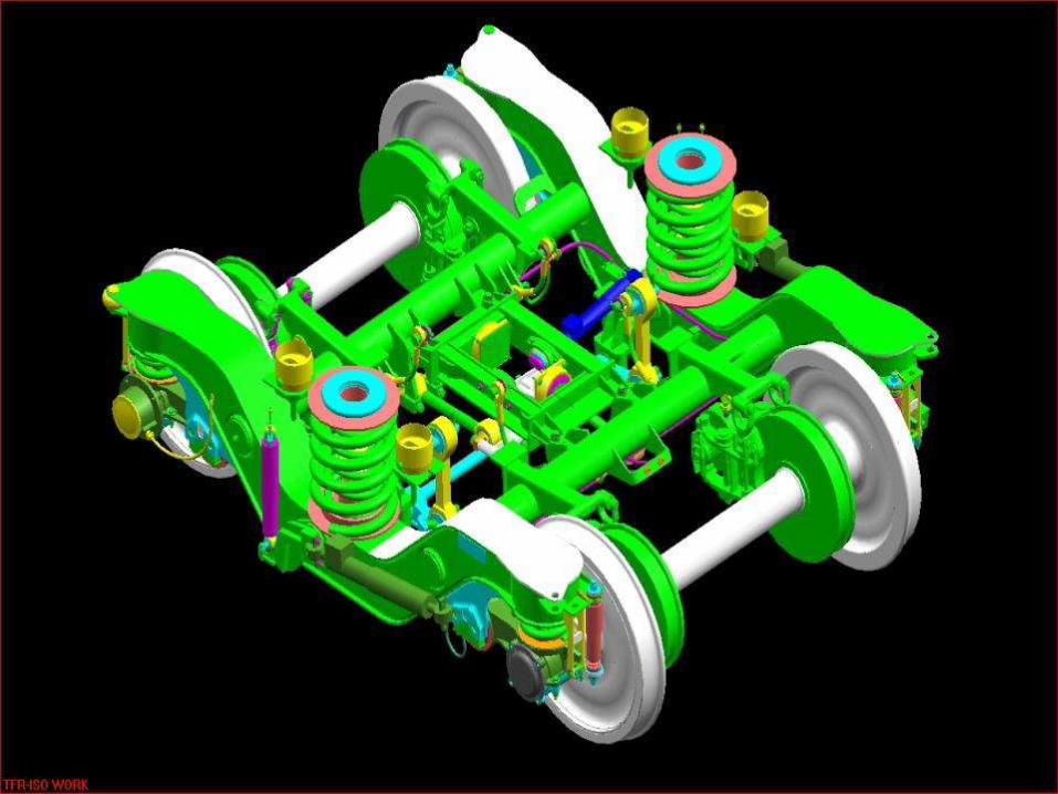
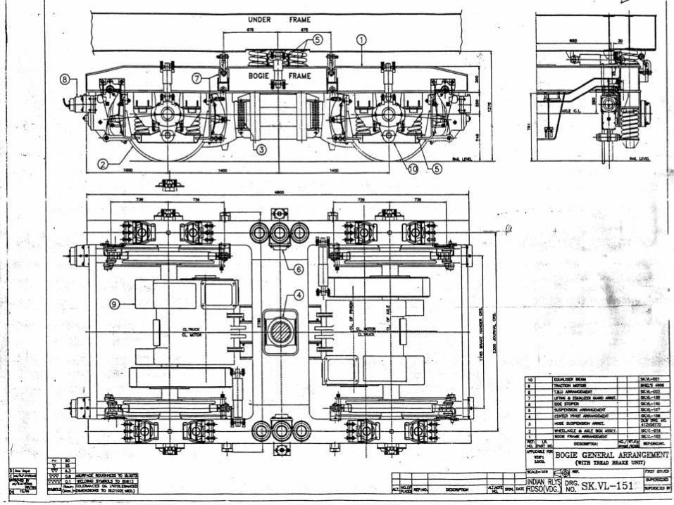
HIGH ADHESION BOGIE


Basic design features
Bogie weight 25t
Axle load 20.5t
Wheel base 3800 mm
Journal centers 2300mm
Designed speed 110km/h
Un-sprung mass 13.05t

Basic design features
Bogie Frame Box Section H type
Horn guide axle guidance
16 nos. primary springs 40.8 kg/mm
08 nos. secondary springs 644 kg/mm
Deflection primary 102mm & Sec. 17 mm
Damper primary Vertical 750 kg/10cm/sec
Damper secondary Lat 1150 kg/10cm/sec

Bo-Bo BOGIE

Two Axle (Bo-Bo) Bogie Axle Load 20 T
Bogie weight 15.5 T
Unsprung weight 4.3T
Wheel base 2800 mm
Journal centre 2300 mm
Speed Potential 120 kmph on Rajdhani Standards track
Two Axle bolsterless bogie with two stage suspension
‘H’ shaped bogie frame of fabricated box type construction
High strength corten steel (IRS M41) used to reduce weight of bogie frame

Two Axle (Bo-Bo) Bogie (contd.)
Helical coil springs used both in Primary & Secondary stages
Floating type centre pivot arrangements for transfer of traction and braking forces between bogie and carbody
Lateral guidance provided between bogie and carbody by flexi-coil action of secondary springs

Two Axle (Bo-Bo) Bogie (contd.)
Conventional horn guide arrangement for transfer of traction & braking forces between axle and bogie frame
Four vertical hydraulic dampers at primary stage, one at each axle box
Two vertical hydraulic dampers & two lateral hydraulic dampers at secondary stage
Axle hung nose suspended BHEL 4906 AZ Traction Motors
Tread brake unit is provided for brake rigging

FLEXI-COIL BOGIE
WDP2 Locomotive


FLEXI-COIL Mk-5 BOGIE FOR WDP2 LOCO
Axle Load 19.5 T.
Speed Potential 160 Km/h on Rajdhani Standard Track.
Three Axle Bogie with Bolster.
Fabricated Box Type Bogie Frame.
Two Stage Suspension with Helical Coil Springs in both the stages.
Lateral guidance between car body & bogie provided by flexi-coil action of secondary springs.

FLEXI-COIL Mk-5 BOGIE FOR WDP2 LOCO (contd.)
Four primary hydraulic vertical dampers, one each at end axle box.
Four vertical hydraulic dampers & two lateral dampers at secondary stage of suspension.
On end axles, axle guidance provided by guide links. On middle axle by conventional horn arrangement.
Functions of guide links: Provides flexible control of lateral & yaw
motion of axle, reduces hunting tendency of bogie.
Transfer of traction & braking force between axle & bogie.

FLEXI-COIL Mk-5 BOGIE FOR WDP2 LOCO (contd.)
Two traction bars ( fitted with pre-compressed rubber pads ) transfer traction and braking forces between bogie & bolster.
Traction bars located at axle box level to minimise weight transfer.
Nylatron liners on
centre pivot provides yaw damping between bolster and car body.
Axle hung nose suspended light weight BHEL 5002 AZ TM with roller suspension bearings.
Conventional type brake rigging arrangement.
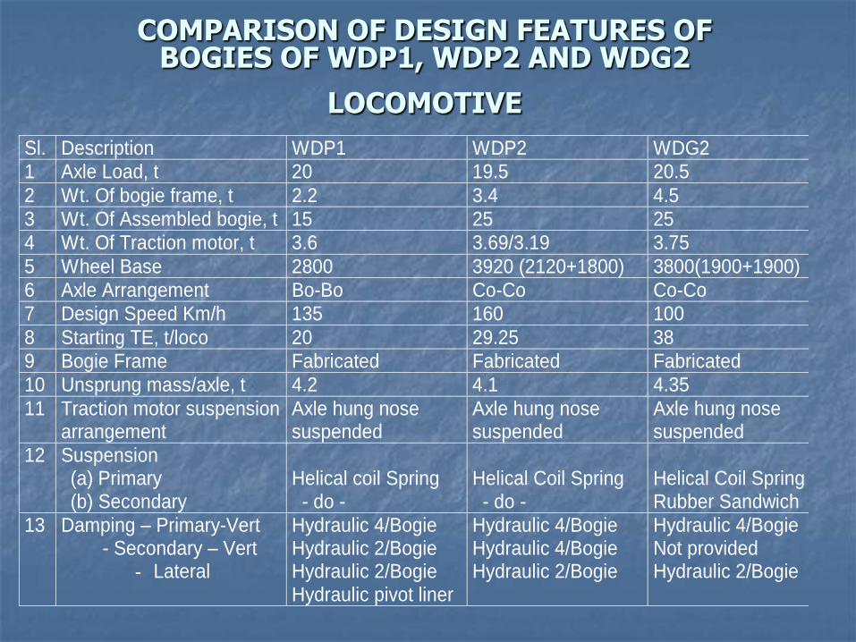
COMPARISON OF DESIGN FEATURES OF BOGIES OF WDP1, WDP2 AND WDG2
LOCOMOTIVE Sl. Description WDP1 WDP2 WDG2
1 Axle Load, t 20 19.5 20.5
2 Wt. Of bogie frame, t 2.2 3.4 4.5
3 Wt. Of Assembled bogie, t 15 25 25
4 Wt. Of Traction motor, t 3.6 3.69/3.19 3.75
5 Wheel Base 2800 3920 (2120+1800) 3800(1900+1900)
6 Axle Arrangement Bo-Bo Co-Co Co-Co
7 Design Speed Km/h 135 160 100
8 Starting TE, t/loco 20 29.25 38
9 Bogie Frame Fabricated Fabricated Fabricated
10 Unsprung mass/axle, t 4.2 4.1 4.35
11 Traction motor suspension arrangement
Axle hung nose suspended
Axle hung nose suspended
Axle hung nose suspended
12 Suspension (a) Primary (b) Secondary
Helical coil Spring - do -
Helical Coil Spring - do -
Helical Coil Spring Rubber Sandwich
13 Damping – Primary-Vert - Secondary – Vert
- Lateral
Hydraulic 4/Bogie Hydraulic 2/Bogie Hydraulic 2/Bogie Hydraulic pivot liner
Hydraulic 4/Bogie Hydraulic 4/Bogie Hydraulic 2/Bogie
Hydraulic 4/Bogie Not provided Hydraulic 2/Bogie

COMPARISON OF DESIGN FEATURES OF BOGIES OF WDP1, WDP2 AND WDG2
LOCOMOTIVE(contd.)
WDP1 WDP2 WDG2
14. Longitudinal guidance of wheel set
Horn guides Guidelink Horn guides
15. Lateral wheel set guidance
Lateral thrust pad
Guide Link thrust pads on end axle boxes
Lateral thrust pad on end axle boxes
16. Longitudinal guidance of loco body
Center pivot with rubber bush
Traction bar fitted with rubber pads at both ends
Center Pivot with rubber bush.
17. Lateral guidance of loco body
Secondary flexi-coil springs
Secondary flexi-coil springs
Secondary rubber sand wich spring.
18. Axle Bearings Cylindrical Roller
Cylindrical Roller
Cylindrical Roller
19. Gear Ratio 18:65 22:61 24:58
20. Main Braking Clasp Type Tread Brake Units (TBUs)
Clasp Type Convl. Brake Rigging
Clasp Type Convl. Brake Rigging

BOGIES FOR EXPORT
TANZANIA
ANGOLA
MOZAMBIQUE
SUDAN ARE……..

TANZANIA

MOZAMBIQUE

ANGOLA

SUDAN