locomotive systems products1565810339/sect-g-locomotive-2018-rs.pdflocomotive systems products...
TRANSCRIPT

Locomotive SystemsProducts
HOT SeriesHead of Train Devices
EOT SeriesEnd of Train Devices G5 - G8G1 - G4
EOT Phone Home SeriesEnd of Train Communications G9 - G10
HOT / EOT Repeater Units Axle DrivesG17 - G20G11 - G12
G-A © Copyright 2018 s Industry Inc.
Locomotive Testing UnitsG13 - G16
Axle GeneratorsG21 - G22
Code Rate Generators / DecodersG23 - G24
OdometersG25 - G26
SpeedometersG27 - G30
Universal Interface PanelsG31 - G32
Ditch LightsG33 - G36

HGR SeriesHeater Ground Relays
MPBIMultiple Penalty Brake Interface G40G37 - G39
GPS Onboard Monitoring UnitG42
Track Receiver Junction Box
Locomotive Power SuppliesG45 - G47
G43ADU SeriesAspect Display Units G44
G-BSIE-RA-CMP-001-18-EN
Q2518Locomotive Alerter System Controller
Locomotive Event RecordersG53 - G55
G48
CHMM SeriesCrash Hardened Memory Modules G51 - G52
Event RecorderCMM / EDAP / COMBINED G56
Availa
ble
2018
Maintenance Key SwitchG41
MULTIPLE PENALTYBRAKE INTERFACE MODULE
D7715H01-A01
REV. SERIAL NO.
EAST PITTSBURGH PA 15112
DecelerometersG49 - G50

G1
Overview
Head of Train Device console model shown for reference purposes only!Actual unit selected may vary in mounting and features.
HOTSeries
Lo
co
mo
tiv
e S
yst
em
s P
rod
ucts
Features
Head of Train Devices
SIEMENS Head Of Train (HOT) units are available in eithera cab mounted model or an integrated model.
The integrated HOT unit is intended for integration into pre-existing locomotive cab electronics such as the General Electric® IFC systems or EMD® / Rockwell® ICE or FIRE systems.
The cab mounted HOT Telemetry unit is intended for applicationto the top of the locomotive control stand or other suitable locations.
Siemens also offers a model that serves as a direct replacement for the Ansaldo STS® Digitair® console mounted unit.
Both series of HOT units, when used with a SIEMENS End Of Train (EOT) unit, will provide the locomotive engineer with important information regarding the operation of the train.
These conditions include brake pipe pressure (PSI) and various status conditions. All HOT units will also process EOT / HOT communications tests, armament requests, and emergency brake commands resulting from an emergency switch activation or external emergency input.
● Built-in status indicators for arming, communications, motion detection, highly visible marker (HVM), brakes and batteries.
● Built-in keypad and display for configuration, troubleshooting and diagnostics.
Able to process End Of Train / Head Of Train communications● tests, armament requests and emergency braking commands.
● Fully supports standard AAR protocols.
● Provides ability to be used as both an internal and / or external event recorder.
© Copyright 2018 s Industry Inc.

NYK:V3465/R
NYK:VK-3465/R
Full Size Console Unit Weight is approx. 11 lbs. (4.99 kgs.) including mounting foot● Operates in -40º F to +160º F (-40ºC to +70ºC) @ up to 95% Non-Condensing Relative Humidity● 13.56” (34.44 cm) Wide x 8.41” (21.36 cm) Deep x 3.85” (9.78 cm) Tall● Includes Ritron® dual band radio● (1) NYK:QP-52321 mounting plate● NYK:QP-16371 PUMP® software update program●
● Bootloader firmware Application firmware●
Full Size Console w/ Setup Kit (1) NYK:V3465/R Full Size Console Unit●
● (1) NYK:Q9266/20 20’ (6 m) antenna cable (1) Instruction manual● (1) NYK:06955 450 MHz - 465 MHz antenna● (1) NYK:Q9077/15C Input / Power cable●
3.5”(8.89 cm)
Chassis
3.85”(9.78 cm)
Overall
13.56”(34.44 cm)
Chassis
12.90”(32.77 cm)
Center to Center13.56”
(34.44 cm)Overall
7.00”(17.78 cm)
Chassis
3.85”(9.78 cm)
Overall
Antenna
InstructionManual
3.00”(7.62 cm)Center to
Center
AssembliesHOT Series - Head Of Train Devices
G2
Lo
co
mo
tiv
e S
yst
em
s P
rod
utc
ts
SIE-RA-CMP-001-18-EN

NYK:V3467/R
NYK:VK-3467/R
Compact Size Console Unit w/ Setup Kit (1) NYK:V3460 Full Size Console Unit●
● (1) NYK:Q9266/20 20’ (6 m) antenna cable (1) Instruction manual● (1) NYK:06955 450 MHz - 465 MHz antenna● (1) NYK:Q9077/15C Input / Power cable●
4.0”(10.16 cm)
Chassis
4.25”(10.80 cm)
Overall
10.00”(25.40 cm)
Chassis
12.90”(32.77 cm)
Center to Center
7.00”(17.78 cm)
Chassis
9.25”(23.50 cm)
Overall
3.3”(8.38 cm)Center to
Center
Compact Console Unit Weight is approx. 6 lbs. (2.72 kgs.) including mounting foot● Operates in -40º F to +160º F (-40ºC to +70ºC) @ up to 95% Non-Condensing Relative Humidity● 10.00” (25.40 cm) Wide x 9.25” (23.50 cm) Deep x 4.25” (10.80 cm) Tall● Includes Ritron® dual band radio● (1) NYK:QP-52321 mounting plate● NYK:QP-16371 PUMP® software update program●Bootloader firmware●
● Application firmware
Antenna
InstructionManual
AssembliesHOT Series - Head Of Train Devices
G3
Lo
co
mo
tiv
e S
yst
em
s P
rod
ucts
© Copyright 2018 s Industry Inc.

NYK:V3451/R2
NYK:V3452/R2
9.0”(22.86 cm)
Overall
2.5”(6.35 cm)
Overall
11.25”(28.58 cm)
Chassis
Integrated Unit Weight is approx. 3 lbs. (1.36 kgs.) including mounting foot● Operates in -40º F to +160º F (-40ºC to +70ºC) @ up to 95% Non-Condensing Relative Humidity● 2.5” (6.35 cm) Wide x 11.25” (28.58 cm) Deep x 9.0” (22.86 cm) Tall● Includes Ritron® dual band radio● NO mounting plate● NYK:QP-16371 PUMP® software update program● Bootloader firmware● Application firmware●
12.75” (32.38 cm)Overall
9.0”(22.86 cm)
Overall
2.5”(6.35 cm)
Overall
11.25”(28.58 cm)
Chassis
12.75” (32.38 cm)Overall
9.0”(22.86 cm)
Overall
2.5”(6.35 cm)
Overall
11.25”(28.58 cm)
Chassis
12.75” (32.38 cm)Overall
9.0”(22.86 cm)
Overall
2.5”(6.35 cm)
Overall
11.25”(28.58 cm)
Chassis
Integrated Unit Weight is approx. 3 lbs. (1.36 kgs.) including mounting foot● Operates in -40º F to +160º F (-40ºC to +70ºC) @ up to 95% Non-Condensing Relative Humidity● 2.5” (6.35 cm) Wide x 11.25” (28.58 cm) Deep x 9.0” (22.86 cm) Tall● Includes Ritron® dual band radio● NO mounting plate● NYK:QP-16371 PUMP® software update program● Bootloader firmware● Application firmware●
G4
Lo
co
mo
tiv
e S
yst
em
s P
rod
utc
ts
AssembliesHOT Series - Head Of Train Devices
SIE-RA-CMP-001-18-EN

G5
Overview
Head of Train Device console model shown for reference purposes only!Actual unit selected may vary in mounting and features.
EOTSeries
SIEMENS End of Train Devices is available with or withoutEOT Phone Home service.
When used in conjunction with the SIEMENS Head of Train Device (HOT) it provides information to the locomotive engineer about the operational conditions / statuses of the train.
Some of the statuses include: ● Brake pipe pressure (psi) ● Arming Status (Emergency feature enabled or disabled) ● Communication Status (Good / Comm-Loss, rear-to-front or front-to-rear)
Motion Detection (Moving or stopped) ● ● High Visibility Marker (HVM) Status (On, off or defective)
Brake value (Normal, emergency or defective) ● Battery State Status (Good, low or dead) ● Battery Charge Status ( % depleted, in charge units) ●
● Single, Push-Button Operation
Single-LED Visibility Marker ●
Cellular Data Service with Over-the-Air Upgrades ●
8 Watt Narrow-Band Radio with Waiver on Annual Calibration ●
Internal Event Recorder and GPS Reciever ●
Enclosed Antenna and AEI Tag ●
Lo
co
mo
tiv
e S
yst
em
s P
rod
ucts
Features
End of Train Devices
© Copyright 2018 s Industry Inc.

G6
AssembliesEOT Series - End Of Train Devices
Lo
co
mo
tiv
e S
yst
em
s P
rod
utc
ts
NYK:QK-3920-01 NYK:QK-3920-02
NYK: NYK:
EOT with EOT Phone Home Included(Red Standard Model)
Weight is approx. 26.5 lbs. (12.02 kgs.)● Operates in -40º F to +160º F (-40ºC to +70ºC) @ up to ●
95% Non-Condensing Relative Humidity 4.50” (11.43 cm) Wide x 8.40” (21.34 cm) Deep x 27.00” (68.58 cm) Tall● Operating voltage 12.5 V to 13.0 V● Power supply 12 V, 3.4 Ah● Charge port 10 pin MS3102E-18-1S connector● Includes EOT Phone Home service● Includes cell modem●
EOT with EOT Phone Home Included(Orange Standard Model)
Weight is approx. 26.5 lbs. (12.02 kgs.)● Operates in -40º F to +160º F (-40ºC to +70ºC) @ up to ●
95% Non-Condensing Relative Humidity 4.50” (11.43 cm) Wide x 8.40” (21.34 cm) Deep x 27.00” (68.58 cm) Tall● Operating voltage 12.5 V to 13.0 V● Power supply 12 V, 3.4 Ah● Charge port 10 pin MS3102E-18-1S connector● Includes EOT Phone Home service● Includes cell modem●
EOT with EOT Phone Home Included(Red Smart Charge Model)
Weight is approx. 26.5 lbs. (12.02 kgs.)● Operates in -40º F to +160º F (-40ºC to +70ºC) @ up to ●
95% Non-Condensing Relative Humidity 4.50” (11.43 cm) Wide x 8.40” (21.34 cm) Deep x 27.00” (68.58 cm) Tall● Operating voltage 12.5 V to 13.0 V● Power supply 12 V, 3.4 Ah● Charge port 10 pin MS3112E-10-6S connector● Includes EOT Phone Home service● Includes cell modem●
EOT with EOT Phone Home Included(Orange Smart Charge Model)
Weight is approx. 26.5 lbs. (12.02 kgs.)● Operates in -40º F to +160º F (-40ºC to +70ºC) @ up to ●
95% Non-Condensing Relative Humidity 4.50” (11.43 cm) Wide x 8.40” (21.34 cm) Deep x 27.00” (68.58 cm) Tall ● Operating voltage 12.5 V to 13.0 V ● Power supply 12 V, 3.4 Ah● Charge port 10 pin MS3112E-10-6S connector● Includes EOT Phone Home service● Includes cell modem●
NYK:QK-3920-03 NYK:QK-3920-04
SIE-RA-CMP-001-18-EN

G7
Lo
co
mo
tiv
e S
yst
em
s P
rod
ucts
Maintenance and DimensionsEOT Series - End Of Train Devices
Applicable for all End of Train (EOT) Devices
8.40”(21.34 cm)
Overall
27.00”(68.58 cm)
Overall
4.50”(11.43 cm)
Overall
s Part Number
End of Train Device Maintenance Parts
NYK:QP-35056 Dump Pilot Valve
NYK:QP35057 APG Control Valve
NYK:59208 APG Assembly
NYK:52616 Clamp Nut Bar
NYK:59062 Latch Handle
NYK:61013 Electronic Interface Module
NYK:62174 Power Module
NYK:62176/PC Clamp Assembly
NYK:65105/ORG Orange Enclosure
NYK:65105/RED Red Enclosure
NYK:65106/ORG Orange Enclosure Cover
NYK:65106/RED Red Enclosure Cover
NYK:QP-52516 Mounting Bracket
NYK:QP-70312 Chassis Harness
© Copyright 2018 s Industry Inc.

Description
G8
Lo
co
mo
tiv
e S
yst
em
s P
rod
utc
ts
SIE-RA-CMP-001-18-EN

G9
Overview
EOT Phone HomeService
Lo
co
mo
tiv
e S
yst
em
s P
rod
ucts
Features
SIEMENS End of Train (EOT) Phone Home solution isa subscription based Telemetry Management Software as a Service (SaaS) application that is designed to support multiple manufacturers and empowers railroad operationspersonnel to efficiently deploy, monitor, track, maintain and manage End of Train (EOT) devices ubiquitously with the ease of a browser based interface.
It has an intuitive user interface that quickly enables even themost casual user to rapidly become proficient in accessing information relative to their interest. Advanced users will also appreciate the ability to perform their tasks with ease utilizing innovative capabilities such as:
Locating missing EOT devices and providing mapped directions● Tracing travel paths and tracking trains ●
(as a backup to other systems)
Configuration management of advanced settings● Track and trace of device maintenance upgrades● Disabling devices that are lost or misappropriated● Billing for device utilization by other railroads● Automated reporting for optimizing device utilization●
Most knowledge users are familiar with web browsers and as such, the Phone Home solution is validated to support the latest versions of Microsoft® Internet Explorer®, Google® Chrome®, and Apple® Safari®, which reduces training costs and provides IT departments a robust environment for managing version control and security policies.
● Color coded Key Performance Indicators (KPIs) for EOT status.
Clustering to efficiently manage map real-estate.●
Paste link feature for proficient collaboration.●
Multiple map base layers for visualizing mapping features.●
Hyperlinked status bar for current quick scroll view of common ● EOT statuses.
Search options dialog box for effortless queries.●
● Saved searches feature for rapid retrieval of common queries.
● Run History Report function with multiple file formats.
© Copyright 2018 s Industry Inc.

G10SIE-RA-CMP-001-18-EN

G11
Overview
Model NYK:Q3442 HOT / EOT Series Repeater Moduleshown for reference purposes only!Actual software may vary in mounting and features.
HOT / EOTSeries
SIEMENS HOT / EOT Series Repeaters are designed to assist communications between SIEMENS Head of Train (HOT) andSIEMENS End of Train (EOT) transceivers where the transmission /reception of these devices may be impeded by other transceivers.
Supports AAR standard transmission protocol on frequency pairs457.9375 MHz and 452.9375 MHz and are designed to operatewithout any user input needed. Once initialized, LED indicatorson the front of the unit provide indications of operating status.
Lo
co
mo
tiv
e S
yst
em
s P
rod
ucts
Repeater Modules
© Copyright 2018 s Industry Inc.

G12
Assemblies and DimensionsHOT / EOT Series - Repeaters
Lo
co
mo
tiv
e S
yst
em
s P
rod
ucts
NYK:Q3440/R NYK:Q3442
Integrated Unit Weight is approx. 7 lbs. (3.18 kgs.) including mounting plate● Operates in -40º F to +160º F (-40ºC to +70ºC) @ up to ●
95% Non-Condensing Relative Humidity 2.7” (6.86 cm) Wide x 13.34” (33.88 cm) Deep x 9.2” (23.69 cm) Tall● Includes 457.9375 MHz and 452.9375 MHz VHF Ritron® radios● (1) NYK:52316 mounting plate● (1) NYK:70126/RR antenna cable● (1) NYK:70145/8 antenna cable●
Integrated Unit for General Electric® IFC, tm tmEMD/Rockwell® ICE or FIRE systems.
Weight is approx. 7 lbs. (3.18 kgs.) including mounting plate● Operates in -40º F to +160º F (-40ºC to +70ºC) @ up to ●
95% Non-Condensing Relative Humidity 2.7” (6.86 cm) Wide x 13.34” (33.88 cm) Deep x 9.2” (23.69 cm) Tall● Includes 457.9375 MHz and 452.9375 MHz UHF Ritron® radios● (1) NYK:52316 Mounting plate● (2) NYK:06966 antenna cables●
9.2”(23.69 cm)
Overall
2.5”(6.35 cm)
Chassis
2.7”(6.86 cm)
Overall
11.50”(29.21 cm)
Chassis
13.34” (33.88 cm)Mounting Plate
12.80” (32.51 cm)Center to Center
7.0” (17.78 cm)Center to
Center
Applicable for all HOT / EOT Repeater modules
SIE-RA-CMP-001-18-EN
G13
Overview
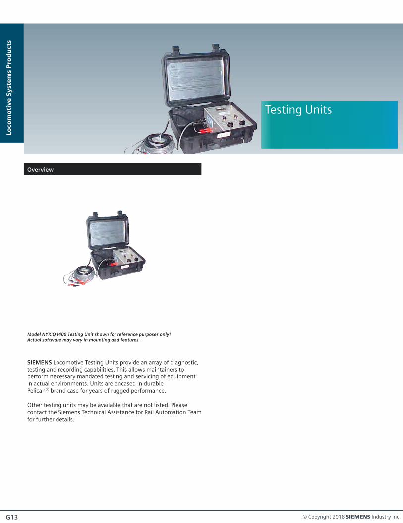
Model NYK:Q1400 Testing Unit shown for reference purposes only!Actual software may vary in mounting and features.
Testing Units
SIEMENS Locomotive Testing Units provide an array of diagnostic,testing and recording capabilities. This allows maintainers toperform necessary mandated testing and servicing of equipmentin actual environments. Units are encased in durable Pelican® brand case for years of rugged performance.
Other testing units may be available that are not listed. Please contact the Siemens Technical Assistance for Rail Automation Teamfor further details.
Lo
co
mo
tiv
e S
yst
em
s P
rod
ucts
© Copyright 2018 s Industry Inc.
G14
AssembliesTesting Units
Lo
co
mo
tiv
e S
yst
em
s P
rod
ucts
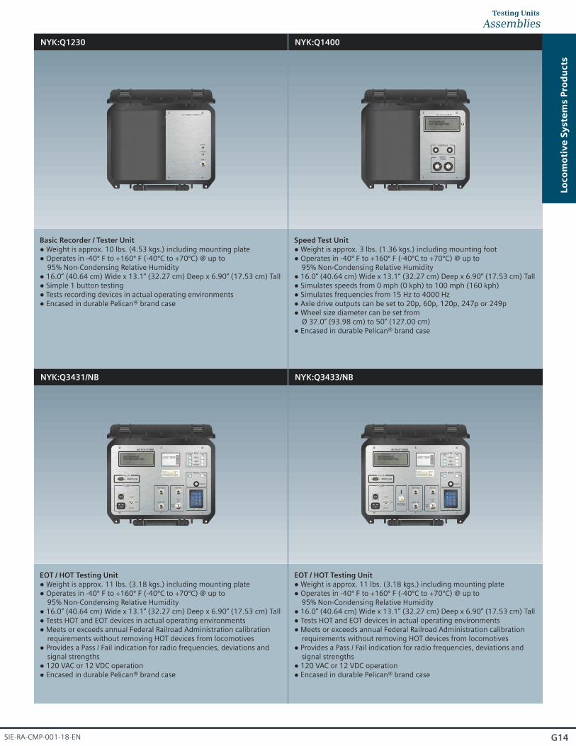
NYK:Q1230 NYK:Q1400
NYK:Q3431/NB NYK:Q3433/NB
Basic Recorder / Tester Unit Weight is approx. 10 lbs. (4.53 kgs.) including mounting plate● Operates in -40º F to +160º F (-40ºC to +70ºC) @ up to ●
95% Non-Condensing Relative Humidity 16.0” (40.64 cm) Wide x 13.1” (32.27 cm) Deep x 6.90” (17.53 cm) Tall● Simple 1 button testing●
● Tests recording devices in actual operating environments Encased in durable Pelican® brand case●
Speed Test Unit Weight is approx. 3 lbs. (1.36 kgs.) including mounting foot● Operates in -40º F to +160º F (-40ºC to +70ºC) @ up to ●
95% Non-Condensing Relative Humidity 16.0” (40.64 cm) Wide x 13.1” (32.27 cm) Deep x 6.90” (17.53 cm) Tall● Simulates speeds from 0 mph (0 kph) to 100 mph (160 kph)● Simulates frequencies from 15 Hz to 4000 Hz● Axle drive outputs can be set to 20p, 60p, 120p, 247p or 249p● Wheel size diameter can be set from ●
Ø 37.0” (93.98 cm) to 50” (127.00 cm)● Encased in durable Pelican® brand case
EOT / HOT Testing Unit Weight is approx. 11 lbs. (3.18 kgs.) including mounting plate● Operates in -40º F to +160º F (-40ºC to +70ºC) @ up to ●
95% Non-Condensing Relative Humidity 16.0” (40.64 cm) Wide x 13.1” (32.27 cm) Deep x 6.90” (17.53 cm) Tall● Tests HOT and EOT devices in actual operating environments● Meets or exceeds annual Federal Railroad Administration calibration ●
requirements without removing HOT devices from locomotives Provides a Pass / Fail indication for radio frequencies, deviations and ●
signal strengths 120 VAC or 12 VDC operation● Encased in durable Pelican® brand case●
SIE-RA-CMP-001-18-EN

NYK:D3005H15-A01 NYK:D3883H32-A01
ATC Tester Unit Weight is approx. 3 lbs. (1.36 kgs.) including mounting foot● Operates in -40º F to +160º F (-40ºC to +70ºC) @ up to ●
95% Non-Condensing Relative Humidity 16.0” (40.64 cm) Wide x 13.1” (32.27 cm) Deep x 6.90” (17.53 cm) Tall●
ACSES transponder simulator control portable tester Weight is approx. 10 lbs. (4.53 kgs.) including mounting plate● Operates in -40º F to +160º F (-40ºC to +70ºC) @ up to ●
95% Non-Condensing Relative Humidity 16.0” (40.64 cm) Wide x 13.1” (32.27 cm) Deep x 6.90” (17.53 cm) Tall●
G15
Lo
co
mo
tiv
e S
yst
em
s P
rod
ucts
AssembliesTesting Units
© Copyright 2018 s Industry Inc.

G16
Lo
co
mo
tiv
e S
yst
em
s P
rod
ucts
SIE-RA-CMP-001-18-EN

G17
Overview
Model Q1165 Axle Drive shown for reference purposes only!Actual software may vary in mounting and features.
Axle Drives
SIEMENS Axle Drives feature solid cast aluminum housing and dual internal bearings for longevity. They can be supplied with either 20 or 60 electrical pulses per wheel revolution.
The dual bearing configuration virtually eliminates any failures dueto excessive stresses from the unsprung axle as the locomotive traverses either rough road crossings or bad joints. These situationscan cause premature fatigue on single bearing model axle drives and therefore failures with a critical component of the event recording or speed indicating system.
A direct replacement for most 20 or 60 pole axle drives in use today, and can be supplied with any length paddle assembly needed by the using railroad including a “peg” drive for some axle applications.
Optional Universal Axle Drive Paddle is constructed with a high tech thermal molded plastic and is a one size fits all solution. Supplied in standard 10” (25.4 cm) length and pre-marked and pre-drilled for easy field modification to field sizes of either 7.5” (19.05 cm) or 3.5” (8.89 cm) long.
Lo
co
mo
tiv
e S
yst
em
s P
rod
ucts
© Copyright 2018 s Industry Inc.

G18
AssembliesAxle Drives - 20 Pulses Per Minute
Lo
co
mo
tiv
e S
yst
em
s P
rod
ucts
NYK:Q1123 NYK:Q1124
NYK:Q1126 NYK:Q1127
20 Pulses Per Minute Weight is approx. 9 lbs. (4.08 kgs.)● Operates in -40º F to +160º F (-40ºC to +70ºC) @ up to ●
95% Non-Condensing Relative Humidity 6.13” (15.57 cm) Wide x 8.13” (20.32 cm) Deep x 9.72” (24.69 cm) Tall● Cast aluminum housing● Dual bearing configuration● NO paddle axle drive shaft assembly● NO PEG drive shaft assembly● NO cables●
20 Pulses Per Minute w/ Paddle Axle Drive Assembly Weight is approx. 9.8 lbs. (4.45 kgs.)● Operates in -40º F to +160º F (-40ºC to +70ºC) @ up to ●
95% Non-Condensing Relative Humidity 6.13” (15.57 cm) Wide x 17.50” (44.45 cm) Deep x 9.72” (24.69 cm) Tall● Cast aluminum housing● (1) NYK:Q1123 Axle Drive (20 Pulses Per Minute) assembly● (1) NYK:QP-52170 Paddle Axle Drive Assembly● NO PEG drive shaft assembly● NO cables●
20 Pulses Per Minute w/ PEG Axle Drive Assembly Weight is approx. 9.4 lbs. (4.26 kgs.)● Operates in -40º F to +160º F (-40ºC to +70ºC) @ up to ●
95% Non-Condensing Relative Humidity 6.13” (15.57 cm) Wide x 8.38” (21.29 cm) Deep x 9.72” (24.69 cm) Tall● Cast aluminum housing● (1) NYK:Q1123 Axle Drive (20 Pulses Per Minute) assembly● NO paddle axle drive assembly● (1) NYK:52272 Peg Drive Assembly● NO Cables●
20 Pulses Per Minute w/ PEG Axle Drive Assembly and Cables Weight is approx. 11 lbs. (4.99 kgs.) including cables● Operates in -40º F to +160º F (-40ºC to +70ºC) @ up to ●
95% Non-Condensing Relative Humidity 16.0” (40.64 cm) Wide x 13.1” (32.27 cm) Deep x 6.90” (17.53 cm) Tall● Cast aluminum housing● (1) NYK:Q1123 Axle Drive (20 Pulses Per Minute) assembly● NO paddle axle drive shaft assembly● (1) NYK:52272 Peg Drive Shaft Assembly● (1) NYK:09255 16.5’ (5 m) cable ●
SIE-RA-CMP-001-18-EN
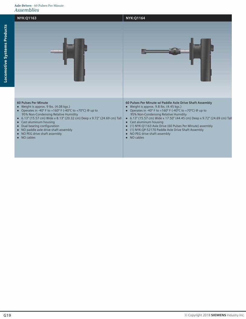
NYK:Q1163 NYK:Q1164
60 Pulses Per Minute Weight is approx. 9 lbs. (4.08 kgs.)● Operates in -40º F to +160º F (-40ºC to +70ºC) @ up to ●
95% Non-Condensing Relative Humidity 6.13” (15.57 cm) Wide x 8.13” (20.32 cm) Deep x 9.72” (24.69 cm) Tall● Cast aluminum housing● Dual bearing configuration● NO paddle axle drive shaft assembly● NO PEG drive shaft assembly● NO cables●
60 Pulses Per Minute w/ Paddle Axle Drive Shaft Assembly Weight is approx. 9.8 lbs. (4.45 kgs.)● Operates in -40º F to +160º F (-40ºC to +70ºC) @ up to ●
95% Non-Condensing Relative Humidity 6.13” (15.57 cm) Wide x 17.50” (44.45 cm) Deep x 9.72” (24.69 cm) Tall● Cast aluminum housing● (1) NYK:Q1163 Axle Drive (60 Pulses Per Minute) assembly● (1) NYK:QP-52170 Paddle Axle Drive Shaft Assembly● NO PEG drive shaft assembly● NO cables●
G19
Lo
co
mo
tiv
e S
yst
em
s P
rod
ucts
AssembliesAxle Drives - 60 Pulses Per Minute
© Copyright 2018 s Industry Inc.

G20
AssembliesAxle Drives
Lo
co
mo
tiv
e S
yst
em
s P
rod
ucts
NYK:52508/20P NYK:52508/60P
NYK:52170 NYK:52272
Axle Drive Shaft Assembly for 20 Pulses Per Minute Weight is approx. 2 lbs. (0.91 kgs.)● Operates in -40º F to +160º F (-40ºC to +70ºC) @ up to ●
95% Non-Condensing Relative Humidity
Axle Drive Shaft Assembly for 60 Pulses Per Minute Weight is approx. 2 lbs. (0.91 kgs.)● Operates in -40º F to +160º F (-40ºC to +70ºC) @ up to ●
95% Non-Condensing Relative Humidity
Paddle Axle Drive Shaft Assembly for 20 Pulses Per Minute Weight is approx. 2 lbs. (0.91 kgs.)● Operates in -40º F to +160º F (-40ºC to +70ºC) @ up to ●
95% Non-Condensing Relative Humidity Pre-marked and pre-drills to field modify for either●
a 7.5” (19.05 cm) or 3.5” (8.89 cm) long
PEG Drive Shaft Assembly for 20 Pulses Per Minute Weight is approx. 1 lbs. (0.45 kgs.)● Operates in -40º F to +160º F (-40ºC to +70ºC) @ up to ●
95% Non-Condensing Relative Humidity
SIE-RA-CMP-001-18-EN

G21
Overview
Axle Generator shown for reference purposes only!Actual unit selected may vary in mounting and features.
Axle Generator
SIEMENS Axle Generator uses internal speed sensors to count pulses related to specific gear rotations. Speed data is relayed to the onboard computer for determination of potential overspeed conditions. It contains (3) magnetic reluctance typespeed sensors. The first two sensors are driven from a 60 tooth gear and the remaining sensor is driven from a 40 tooth gear.
Other configurations may be available that are not listed. Please contact the SIEMENS Technical Assistance for Rail Automation Team for further details.
NYK:D600001-A01
● Meets or exceeds applicable AREMA® specifications on recommended practices regarding 3000 VAC breakdown voltage.
Easily mountable on standard relay racks, instrument house● backboards or can even be shelf mounted when removing included mounting bracket
Weight is approx. 15 lbs. (6.80 kgs.) including connectors● Operates in -40º F to +160º F (-40ºC to +70ºC) @ up to ●
95% Non-Condensing Relative Humidity 6.3 VAC 3.5 Amp power supply●
● (1) 15 Amp battery fuse (1) 1.5 Amp line fuse● (4) Output battery connections● 115 VAC Input connection● 12 VDC Input connection●
Lo
co
mo
tiv
e S
yst
em
s P
rod
ucts
Optional Accessories
NYK:D1365H01-A12
Part Number
Junction box
Description
NYK:B600010-A01 Spline assembly
© Copyright 2018 s Industry Inc.

G22
Lo
co
mo
tiv
e S
yst
em
s P
rod
ucts
SIE-RA-CMP-001-18-EN

Overview
Code Rate Generator / Decoder shown for reference purposes only!Actual unit selected may vary in mounting and features.
Code RateGenerators / Decoders
SIEMENS Code Rate Generator is a microprocessor based unit used to drive code following relays. The unit generates various code rates depending on model.
An integrated LED flashes at the generated code rate. The attached mounting plate can be supplied with different dimensions to match various relay mounting patterns.
Lo
co
mo
tiv
e S
yst
em
s P
rod
ucts
● Solid state design that replaces older relays
Vital design ensures that transmitted code is never greater than ● the one selected
Stainless steel enclosure, hardware and mounting plate●
Utilizes industry standard AAR terminals●
Features
G23 © Copyright 2018 s Industry Inc.

NYK:D887H01-A01
Code Rate Decoder Weight is approx. 4 lbs. (1.81 kgs.)● Operates in -40º F to +160º F (-40ºC to +70ºC) @ up to ●
95% Non-Condensing Relative Humidity 8 VDC - 15 VDC voltage range●
● 250 mA nominal input current (neglecting load current) 12 V nominal relay coil with 500 output load● > Ω Outputs rated at 0.75A @ 12 V● Generates code rates 75, 120, and180●
NYK:D243H01-A01
Code Rate Generator Weight is approx. 4 lbs. (1.81 kgs.)● Operates in -40º F to +160º F (-40ºC to +70ºC) @ up to ●
95% Non-Condensing Relative Humidity 8 VDC - 15 VDC voltage range●
● Current sinking outputs 250 mA nominal input current (neglecting load current)● Open drain FET output load● Outputs rated at 0.75A @ 12 V● Generates code rates 50, 75, 120, 180, 270 and 420●
G24
AssembliesCode Rate Generators / Decoders
Lo
co
mo
tiv
e S
yst
em
s P
rod
ucts
Applicable for all Code Rate Generators and Decoders
8.50”(21.59 cm)
Overall
10.25”(26.04 cm)
Overall
2.5”(6.35 cm)Center to
Center4.88”
(12.40 cm)Overall
0.5”(1.27 cm)
2.5”(6.35 cm)Center to
Center
0.5”(1.27 cm)
SIE-RA-CMP-001-18-EN

G25
Overview
Model NYK:Q1860 Odometer shown for reference purposes only!Actual unit selected may vary in mounting and features.
Odometers
SIEMENS Odometer is a self-contained module for permanently recording vehicle mileage. Vehicle mileage, in 1 mile increments to 9,999,999 miles on Q1860 model (1 kilometer increments to 9,999,999 kilometers on Q1860/M model) is continuously displayed on the integrated and back-lit Liquid Crystal Display (LCD).
Accumulated mileage is stored in 10 mile (10 kilometer) increments in non-volatile memory for permanent recording. Installation consists of physically mounting the electronics enclosure and completing the wiring the to power and the axle alternator of the vehicle. The serial communication interface, a standard DB-9 computer connector, allows various operating parameters to be changed including the axle alternator poles per revolution, wheel diameter and initial mileage setting.
Lo
co
mo
tiv
e S
yst
em
s P
rod
ucts
© Copyright 2018 s Industry Inc.

NYK:Q1860
Weight is approx. 4 lbs. (1.81 kgs.)● Operates in -40º F to +160º F (-40ºC to +70ºC) @ up to ●
95% Non-Condensing Relative Humidity Measures in MPH●
NYK:Q1860/M
● Weight is approx. 4 lbs. (1.81 kgs.) Operates in -40º F to +160º F (-40ºC to +70ºC) @ up to ●
95% Non-Condensing Relative Humidity Measures in KPH●
8.40”(21.34 cm)
Overall
7.4”(12.40 cm)
Center to Center
3.0”(7.62 cm)Center to
Center
0.5”(1.27 cm)
0.5”(1.27 cm)
4.13”(10.49 cm)
Overall
4.13”(10.49 cm)
Overall
Applicable for all Odometers
G26
Assemblies and DimensionsOdometers
Lo
co
mo
tiv
e S
yst
em
s P
rod
ucts
SIE-RA-CMP-001-18-EN
Locomotive
G27
Overview
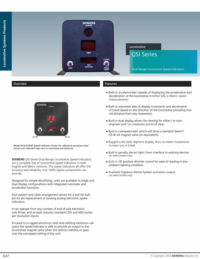
Model NYK:Q1830 Speed Indicator shown for reference purposes only!Actual unit selected may vary in mounting and features.
Lo
co
mo
tiv
e S
yst
em
s P
rod
ucts
Features
SIEMENS QSI Series Dual Range Locomotive Speed Indicators are a complete line of locomotive speed indicators in both English and Metric versions. The speed indicators all offer theaccuracy and reliability only 100% digital components can provide.
Designed for simple retrofitting, units are available in single anddual display configurations with integrated odometer andaccelerator functions.
Foot pattern and cable arrangement allows for a bolt for bolt, pin for pin replacement of existing analog electronic speed indicators.
It can operate from any number of end of axle electronic axle drives, and accepts industry standard (20) and (60) pulses per revolution inputs.
Encased in a rugged aluminum shell and utilizing minimum cabspace the speed indicator is able to provide an output to thelocomotive magnet valve when the vehicle matches or goes over the overspeed setting of the unit.
● Built-in accelerometer capable of displaying the acceleration and deceleration of the locomotive in either SAE or Metric speed measurements.
● Built-in odometer able to display increments and decrements of travel based on the direction of the locomotive providing true net distance from any movement.
Built-in dual display allows for viewing for either / or train ● engineer and / or conductor points of view.
Built-in overspeed alert which will drive a standard Salem® ● SA-812A magnet valve (or equivalent).
● Rugged solid state segment display, thus no meter movements to wear out or break.
● Built-in penalty alerter light / horn interface to existing devices. (on select models only)
(4) position dimmer control for ease of reading in any ● Built-in ambient lighting condition.
Vigilance Alerter System activation output.● Available (on select models only)
QSI Series
Dual Range Locomotive Speed Indicators
© Copyright 2018 s Industry Inc.

s Part Number
SpeedPreset
NYK:Q1810 None
AssembliesSpeed Indicators
SpeedReadout
EnglishOnly
AdjustableWheel Size
36 mm- 42 mm
AlerterActivation
Output
None
OverspeedRange
5 mph - 99 mph
NYK:Q1810-74 74 mph EnglishOnly
36 mm- 42 mm
None 5 mph - 99 mph
NYK:Q1810/M-120 120 kph English /Metric
36 mm- 42 mm
None5 mph - 99 mph8 kph - 159 kph
NYK:Q1812 None EnglishOnly
36 mm- 42 mm
Vigilance 5 mph - 99 mph
NYK:Q1812-69 69 mph EnglishOnly
36 mm- 42 mm
Vigilance 5 mph - 99 mph
NYK:Q1818-74 74 mph EnglishOnly
30 mm- 38 mm
Vigilance 5 mph - 99 mph
NYK:Q1818-80 80 mph EnglishOnly
30 mm- 38 mm
Vigilance 5 mph - 99 mph
NYK:Q1820 None EnglishOnly
36 mm- 42 mm
Vigilance 5 mph - 99 mph
NYK:Q1820-45 45 mph EnglishOnly
36 mm- 42 mm
Vigilance 5 mph - 99 mph
NYK:Q1820-71 71 mph EnglishOnly
36 mm- 42 mm
Vigilance 5 mph - 99 mph
NYK:Q1820-74 74 mph EnglishOnly
36 mm- 42 mm
Vigilance 5 mph - 99 mph
NYK:Q1820-80 80 mph EnglishOnly
36 mm- 42 mm
Vigilance 5 mph - 99 mph
NYK:Q1821 None MetricOnly
36 mm- 42 mm
Vigilance 8 kph - 160 kph
NYK:Q1830 None EnglishOnly
36 mm- 42 mm
Vigilance 5 mph - 99 mph
NYK:Q1830-10 10 mph EnglishOnly
36 mm- 42 mm
Vigilance 5 mph - 99 mph
NYK:Q1830-69 69 mph EnglishOnly
36 mm- 42 mm
Vigilance 5 mph - 99 mph
RecoveryDelay
30 sec
1 sec
1 sec
1 sec
30 sec
30 sec
30 sec
30 sec
30 sec
30 sec
30 sec
30 sec
30 sec
30 sec
30 sec
30 sec
NYK:Q1830-74 74 mph EnglishOnly
36 mm- 42 mm
Vigilance 5 mph - 99 mph 1 sec
G28
Lo
co
mo
tiv
e S
yst
em
s P
rod
ucts
SIE-RA-CMP-001-18-EN

G29
Lo
co
mo
tiv
e S
yst
em
s P
rod
ucts
CablesSpeed Indicators
Speed Indicator Power Cable (20) Pole
Description
Q9011/10B 10’ (3 m) long, 90° “B” Break
Q9011/10C 10’ (3 m) long, 90° “C” Break
Q9011/15B 15’ (4.5 m) long, 90° “B” Break
Q9011/15C 15’ (4.5 m) long, 90° “C” Break
Q9011/20B 20’ (6 m) long, 90° “B” Break
Q9011/20C 20’ (6 m) long, 90° “C” Break
s Part Number
Speed Indicator Power Cable (20) Pole
Description
NYK:Q9011/10B 10’ (3 m) long, 90° “B” Break
NYK:Q9011/10C 10’ (3 m) long, 90° “C” Break
NYK:Q9011/15B 15’ (4.5 m) long, 90° “B” Break
NYK:Q9011/15C 15’ (4.5 m) long, 90° “C” Break
NYK:Q9011/20B 20’ (6 m) long, 90° “B” Break
NYK:Q9011/20C 20’ (6 m) long, 90° “C” Break
s Part Number
Speed Indicator Power Cable (60) Pole
Description
NYK:Q9012/10B 10’ (3 m) long, 90° “B” Break
NYK:Q9012/10C 10’ (3 m) long, 90° “C” Break
NYK:Q9012/15B 15’ (4.5 m) long, 90° “B” Break
NYK:Q9012/15C 15’ (4.5 m) long, 90° “C” Break
NYK:Q9012/20B 20’ (6 m) long, 90° “B” Break
NYK:Q9012/20C 20’ (6 m) long, 90° “C” Break
s Part Number
Speed Indicator / Alerter Interface Cables
Description
NYK:Q9038/15C 15’ (4.5 m) long, 90° “C” Break
NYK:Q9038/25C 25’ (7.5 m) long, 90° “C” Break
NYK:Q9038/30C 30’ (9 m) long, 90° “C” Break
s Part Number
© Copyright 2018 s Industry Inc.
G30
Lo
co
mo
tiv
e S
yst
em
s P
rod
ucts
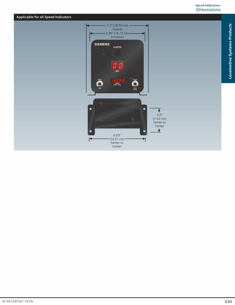
DimensionsSpeed Indicators
Applicable for all Speed Indicators
7.3” (18.55 cm)Overall
5.80” (14.73 cm)Enclosure
6.50”(16.51 cm)Center to
Center
3.0”(7.62 cm)Center to
Center
SIE-RA-CMP-001-18-EN

G31
Overview
Model NYK:Q1250 Universal Interface Panel shown for reference purposes only!Actual unit selected may vary in mounting and features.
Universal InterfacePanels
SIEMENS Universal Interface Panels are a self contained, microprocessor driven device which translates input signals from traction motor speed sensors to industry standard (and user selectable) wheel rotation frequencies.
Designed to replace existing locomotive mechanical axle drive assemblies with solid state sensors and by physically locating the sensors inside the locomotive; increased mechanical reliability is obtained.
Each of two (2) input, processing and output stages electrically independent; hence, the existing locomotive scheme for providing redundant speed input signals is maintained.
Provides outputs to other locomotive borne devices which control the authority for movement along the right-of-way, the output accuracy of the QUIP is within 1% of the input signal over the entire 10 HZ to 10KHz range on all output channels.
Failure modes for the Universal Interface Panel have been investigated through the use of Failure Mode Effects Analysis (FMEA) techniques for hardware, software and the interaction between these components. Any failure from any source will be detected and provide relay output of the fault condition to any externally connected device.
Lo
co
mo
tiv
e S
yst
em
s P
rod
ucts
● Adjustable overspeed function
74 VDC Power●
● 30 second overspeed recovery delay
(1) 20 pole output●
(1) 60 pole output●
(1) 1:500 pole output●
Features
© Copyright 2018 s Industry Inc.

s Part Number
Preset
NYK:Q1250 None
AssembliesUniversal Interface Panels
Self TestSwitch Option
NO
G32
Lo
co
mo
tiv
e S
yst
em
s P
rod
ucts
NYK:Q1251 128 PPWR YES
NYK:Q1253 249 PPWR NO
NYK:Q1254 128 PPWR NO
NYK:Q1260 249 PPWR NO
SIE-RA-CMP-001-18-EN

G33
Overview
Model NYK:Q2014 Ditch Light shown for reference purposes only!Actual unit selected may vary in mounting and features.
Ditch Lights
SIEMENS Ditch Lights are a complete lighting system to retrofitexisting on-board locomotive lights which provides additional visibility during night time operation as well as additionalprotection at grade crossings. Available in either a 32Vdc or 5Vdc versions and powered by an external lighting controller.
Whenever the headlight of the lead locomotive is placed in the high beam position, the ditch lights are constantly illuminated. Whenever speeds are greater than 8 mph (13 kph), whenever the locomotive horn is blown, or when the manual mushroom switchpendant is pressed, the Ditch Lights enter into an alternating wig / wag flashing pattern at 1 second intervals.
Additionally, the lights will continue to flash for approximately 30 seconds before they are extinguished.
Available ditch light brackets can be used for precise aiming of theditch lights according to railroad specifications.
Lo
co
mo
tiv
e S
yst
em
s P
rod
ucts
● Available in either a 32Vdc or 74Vdc versions
● Steel enclosure for rugged durability
Provides additional visibility during night time● operations
Features
© Copyright 2018 s Industry Inc.

NYK:Q2014/30V NYK:Q2014/75V
Type 1 - 30 V Weight is approx. 7 lbs. (3.18 kgs.)● Operates in -40º F to +160º F (-40ºC to +70ºC) @ up to ●
95% Non-Condensing Relative Humidity Type 1 assembly●
● Requires 30 V Bulb
Type 1 - 75 V Weight is approx. 7 lbs. (3.18 kgs.)● Operates in -40º F to +160º F (-40ºC to +70ºC) @ up to ●
95% Non-Condensing Relative Humidity Type 1 assembly●
● Requires 75 V Bulb
11.00”(27.94 cm)
Overall
5.37”(13.64 cm)
Overall
10.00”(25.4 cm)Enclosure
9.4”(22.86 cm)Enclosure
9.77”(24.82 cm)
Overall
Applicable for all NYK:Q2014 Type 1 Ditch Lights
4.62”(11.74 cm)Enclosure
Assemblies and DimensionsDitch Lights - Type 1
G34
Lo
co
mo
tiv
e S
yst
em
s P
rod
ucts
SIE-RA-CMP-001-18-EN

Applicable for all NYK:Q2015 Type 2 Ditch Lights
NYK:Q2015/30V NYK:Q2015/75V
Type 2 - 30 V Weight is approx. 7 lbs. (3.18 kgs.)● Operates in -40º F to +160º F (-40ºC to +70ºC) @ up to ●
95% Non-Condensing Relative Humidity● Type 1 assembly
Requires 30 V Bulb●
Type 2 - 75 V Weight is approx. 7 lbs. (3.18 kgs.)● Operates in -40º F to +160º F (-40ºC to +70ºC) @ up to ●
95% Non-Condensing Relative Humidity Type 1 assembly● Requires 75 V Bulb●
10.00”(25.4 cm)Enclosure
3.37”(8.56 cm)Enclosure
11.42”(29.00 cm)
Overall
4.75”(12.07 cm)
Overall
10.50”(26.67 cm)
Overall
Assemblies and DimensionsDitch Lights - Type 2
G35
Lo
co
mo
tiv
e S
yst
em
s P
rod
ucts
© Copyright 2018 s Industry Inc.

NYK:Q2030C NYK:Q2032C
Ditch Light Controller Weight is approx. 8.2 lbs. (3.72 kgs.)● Operates in -40º F to +160º F (-40ºC to +70ºC) @ up to ●
95% Non-Condensing Relative Humidity● Controls up to (4) @ up to 75 V bulbs
10 second wig / wag timing● 8 mph trigger for lights●
Ditch Light Controller Weight is approx. 8.6 lbs. (3.90 kgs.)● Operates in -40º F to +160º F (-40ºC to +70ºC) @ up to ●
95% Non-Condensing Relative Humidity Controls up to (4) @ up to 75 V bulbs● 10 second wig / wag timing● 5 mph trigger for lights●
Applicable for all Ditch Light Controllers
Assemblies and DimensionsDitch Lights - Controllers
G36
Lo
co
mo
tiv
e S
yst
em
s P
rod
ucts
8.00”(20.32 cm)Enclosure
8.75”(22.23 cm)
Center to Center
9.5”(24.13 cm)
Overall
6.00”(15.24 cm)Center to
Center
8.00”(20.32 cm)Enclosure
SIE-RA-CMP-001-18-EN

G37
Overview
Model NYK:D3676H01 Heater Ground Relay shown for reference purposes only!Actual unit selected may vary in mounting and features.
Heater Ground Relays
SIEMENS Heater Ground Relays provide dual channel fault current monitoring protection for heater systems. Able to be resetautomatically with programmable trip threshold settings. Containsboth internal and external trip indicators. Available in either a600 VDC or 750 VDC version.
Lo
co
mo
tiv
e S
yst
em
s P
rod
ucts
© Copyright 2018 s Industry Inc.

NYK:D1582H01 NYK:D3676H01
600 VDC Weight is approx. 6.4 lbs. (2.90 kgs.)● Operates in -40º F to +160º F (-40ºC to +70ºC) @ up to ●
95% Non-Condensing Relative Humidity
750 VDC Weight is approx. 7.6 lbs. (3.45 kgs.)● Operates in -40º F to +160º F (-40ºC to +70ºC) @ up to ●
95% Non-Condensing Relative Humidity
AssembliesHeater Ground Relays
G38
Lo
co
mo
tiv
e S
yst
em
s P
rod
ucts
SIE-RA-CMP-001-18-EN

Applicable for all NYK:D3676H01 Heater Ground Relays
DimensionsHeater Ground Realys
G39
Applicable for all NYK:D1582H01 Heater Ground Relays
1.13”(2.87 cm)Center to
Center
5.02”(12.75 cm)
Overall
2.12”(5.38 cm)
Overall
4.11”(10.44 cm)Enclosure
7.00(17.78 cm)
Overall
0.54”(1.37 cm)
6.44”(16.36 cm)Center to
Center
6.01”(15.27 cm)Enclosure
0.28”(7.11 cm)
5.97”(15.16 cm)
Overall
3.00”(7.62 cm)Enclosure
4.25”(10.80 cm)Enclosure
6.00”(26.67 cm)
Overall
3.63”(9.22 cm)Center to
Center
0.25”(0.64 cm)
4.00”(10.16 cm)Center to
Center
1.00”(2.54 cm)
Lo
co
mo
tiv
e S
yst
em
s P
rod
ucts
© Copyright 2018 s Industry Inc.

G40
Lo
co
mo
tiv
e S
yst
em
s P
rod
ucts
Overview
MPBI
Features
Multiple Penalty Brake Interface
Multiple Penalty Brake Interface Module shown for reference purposes only! Actual unit selected may vary in mounting and features.
SIEMENS Multiple Penalty Brake Interface (MPBI) in intended to provide a vital “AND” function to allow multiple train control system's penalty brake outputs access to a single penalty brake input to the brake system.
Train Control SystemsThe MPBI device provides support for the various train control systems in use today:
Siemens Cab Signaling System (ATC / ACSES) ● Alstom® ITCS® / X-ITCS® Cab Signaling System ● Ansaldo STS® MicroCad® Cab Signaling System ● Wabtec® I-ETMS ● ™
The MPBI provides railroads with a safe and convenient way to connect their various Positive Train Control (PTC) systems on board their vehicles to the single penalty brake.
● Solid-state LED Indicators
● Lamp Test Pushbutton
● Microprocessor Based
● Vital Design
● Up to 4 Inputs
● Multiple Cutout Options
● Source of Penalty Indicators
MULTIPLE PENALTYBRAKE INTERFACE MODULE
D7715H01-A01
REV. SERIAL NO.
EAST PITTSBURGH PA 15112
DescriptionSIEMENS Part Number
NYK:D7715H03-A01 Penalty Brake Cutout Switch
NYK:D7715H04-A01 Penalty Brake Indicator
NYK:D7715H03-A01 Penalty Brake Interface Module
SIE-RA-CMP-001-18-EN

Overview
Model NYK:C655H01-A02 Maintenance Key Switchshown for reference purposes only!Actual unit selected may vary in mounting and features.
Maintenance Key Switch
SIEMENS Maintenance Key Switch provides exceptional maintenance security and safety in a single compact lightweight aluminum design. Locking cylinder is surrounded by a strong electro-less nickle plated steel body for added security.
The locking cylinders are designed to be “self-cleaning”, sweeping out dirt and grit when operated by controlled keys that are only available to the railroad.
Key retaining design traps the key in the padlock so that it cannot be removed when in the ON position.
NYK:C655H01-A02
● Weight is approx. 3.0 lbs. (1.36 kgs.) Operates in -40º F to +160º F (-40ºC to +70ºC) @ up to ●
95% Non-Condensing Relative Humidity (2) NO and (2) NC contacts, 15A● 15A● 125 VAC● Connection by AAR terminals●
G41
Lo
co
mo
tiv
e S
yst
em
s P
rod
ucts
4.00”(10.16 cm)Center to
Center
5.00”(12.70 cm)
Overall
7”(17.78 cm)
Overall
6.00”(15.24 cm)Center to
Center
4.00”(10.16 cm)
Overall
© Copyright 2018 s Industry Inc.

Overview
Model NYK:D1563H18-A01 GPS Onboard Monitoring Unitshown for reference purposes only!Actual unit selected may vary in mounting and features.
GPS OnboardMonitoring Unit
SIEMENS GPS Onboard Monitoring Unit works by continuallycomparing satellite-derived coordinates to coordinates in the cab system’s onboard database. Database mapping and interface services are also available.
NYK:D1563H18-A01
● Weight is approx. 3.0 lbs. (1.36 kgs.) Operates in -40º F to +160º F (-40ºC to +70ºC) @ up to ●
95% Non-Condensing Relative Humidity
G42
Lo
co
mo
tiv
e S
yst
em
s P
rod
ucts
6.00”(15.25 cm)Center to
Center
9.75”(2.72 cm)Center to
Center
7.50”(19.50 cm)
Overall
10.50”(26.67 cm)
Overall
SIE-RA-CMP-001-18-EN

Overview
Model NYK:D1365H01-A01 Track Receiver Junction Boxshown for reference purposes only!Actual unit selected may vary in mounting and features.
Track ReceiverJunction Box
SIEMENS Track Receiver Junction Boxes are used to wire a pair of track receivers in a series-aiding configuration, providing a single-cable run to the equipment enclosure.
NYK:D1365H01-A01
● Weight is approx. 22.0 lbs. (9.98 kgs.) Operates in -40º F to +160º F (-40ºC to +70ºC) @ up to ●
95% Non-Condensing Relative Humidity
G43
Lo
co
mo
tiv
e S
yst
em
s P
rod
ucts
4.61”(11.71 cm)
Overall
8.63”(21.92 cm)
Overall
4.75”(12.07 cm)Center to
Center
9.16”(23.27 cm)
Overall
7.25”(18.42 cm)Center to
Center
© Copyright 2018 s Industry Inc.

Overview
Aspect Display Unit shown for reference purposes only!Actual unit selected may vary in mounting and features.
Aspect Display Units
Federal Railroad Administration (FRA)Positive Train Control (PTC) Type approved for Northeast Corridor (NEC)
SIEMENS Aspect Display Unit (ADU) provides a primary visual interface between a train’s vehicle operator and the cab signaling systems. The ADU’s rugged design is suitable for use onboard any type of vehicle. The ADU’s microprocessor combines indications from industry standard positive train control protection systems such as Automatic Train Control (ATC) and Advanced Civil Speed Enforcement System (ACSES) in order to present their required respective data concisely thru the ADU onboard display.
The ADU connects serially to either ATC system directly or third-party ATC systems thru a separate ATC Interface Unit (AIU).
Features
G44
Lo
co
mo
tiv
e S
yst
em
s P
rod
ucts
Solid state LED indicators provide reliable, long lasting color with high visibility in all lighting conditions, including on bright sunny days. Alphanumeric display creates an environment for easily reading aspects from multiple railroads as well as important message information. Display automatically dims when necessary to handle varying environmental lighting conditions.
Built in Sonalerts draw vehicle operator’s attention to the ADU when needed to advise of changes in speed information displayed.
iAssembly configurations shown are only a small sampling of commonly ordered assemblies. Other configurations may be available upon request. Please contact the Technical Assistance for Rail Automation team @ 1-800-793-7233 (Option 1) or [email protected] for additional details.
SIE-RA-CMP-001-18-EN

Overview
Model NYK:D1517H01-A01 Locomotive Power Supplyshown for reference purposes only!Actual unit selected may vary in mounting and features.
LocomotivePower Supplies
G45
Lo
co
mo
tiv
e S
yst
em
s P
rod
ucts
© Copyright 2018 s Industry Inc.

NYK:D1517H01-A01 NYK:D5600H01-A01
ACSES Radio Power Supply● Weight is approx. 2.8 lbs. (1.27 kgs.)● Operates in -40º F to +160º F (-40ºC to +70ºC) @ up to 95% Non-Condensing Relative Humidity
13.6 VDC output set point●
32 VDC Weight is approx. 4.3 lbs. (1.95 kgs.)●
● Operates in -40º F to +160º F (-40ºC to +70ºC) @ up to 95% Non-Condensing Relative Humidity
NYK:D1567H08-A01
36 VDC Weight is approx. 4.3 lbs. (1.95 kgs.)●
● Operates in -40º F to +160º F (-40ºC to +70ºC) @ up to 95% Non-Condensing Relative Humidity
NYK: D5600H01-A02
12 VDC (CTV) Weight is approx. 4.3 lbs. (1.95 kgs.)●
● Operates in -40º F to +160º F (-40ºC to +70ºC) @ up to 95% Non-Condensing Relative Humidity
G46
Lo
co
mo
tiv
e S
yst
em
s P
rod
ucts
AssembliesLocomotive Power Supplies
SIE-RA-CMP-001-18-EN

Applicable for all NYK:D5600H01 Locomotive Power Supplies
DimensionsLocomotive Power Supplies
G47
Applicable for all NYK:D1517H01 Locomotive Power Supplies
Lo
co
mo
tiv
e S
yst
em
s P
rod
ucts
2.88”(7.32 cm)
Overall
9.75”(24.77 cm)
Overall
7.25”(18.42 cm)
Overall
4.31”(10.95 cm)
Overall
6.5”(16.51 cm)
Overall
8.25”(20.96 cm)
Overall
© Copyright 2018 s Industry Inc.

G48
Lo
co
mo
tiv
e S
yst
em
s P
rod
ucts
SIEMENS Q518 Locomotive Alerter System Controller provides a Locomotive Engineer reset timer which assures the locomotive crew is attentive to the operation of the locomotive at all times.
Unit is used in conjunction with the SIEMENS Q2505 Alerter Light / Horn unit or SIEMENS QSI Series Speed Indicatorsto provide visual and audible signals to the locomotive crew.
In the event that the crew is unable to continue to operate the locomotive, and have not responded to the alerter system visual and audible alarms, the alerter system will initiate a penalty brake application of the train brakes.
Under normal operating conditions, the alerter system does not interfere with the customary activities of the engineer since the alerter system is reset by all of the train crew operated locomotive controls.
● Provides full redundancy by incorporating (2) microprocessors to not only monitor all inputs to the unit but also control half of the units visual indicators and (1) of the (2) audible horns.
● Provides Speed Dependent Timing Cycle which allows the locomotive speed signal to vary unit’s timing cycle. As the speed of the locomotive increases, the timing cycle decreases.
● Includes Body on Board (BOB) function which requires one (1) acknowledgment by locomotive crew of the visual and audible alarm indications before the system will increase the timing cycle above its most restrictive setting. This ensures that a minimum distance will be traveled if the locomotive brakes are released without a crew member on board that is capable of operating the locomotive.
● Includes Repetitive Reset Disable which monitors the manual reset switch input for the presence of repetitive inputs. Any mechanical or electrical means of providing repetitive resets to the manual reset switch input will not be processed as a valid timing or alarm cycle reset.
● Features a self test mode, allowing railroad maintenance personnel to quickly evaluate all functions and reset inputs.
Features a modular design, which allows each component of the● unit to be changed quickly, when required.
Q2518
Locomotive Alerter System Controller
Overview
Features
SIE-RA-CMP-001-18-EN

Overview
Model NYK:D1563H18-A01 Decelerometer shown for reference purposes only!Actual unit selected may vary in mounting and features.
Decelerometer
G49
Lo
co
mo
tiv
e S
yst
em
s P
rod
ucts
SIEMENS Decelerometer are a solid state design, vital, microprocessor-controlled device used to determine a vehicle’s deceleration rate.
Designed using fail-safe principles to ensure that deceleration rate cannot be erroneously obtained. These include both Class I hardware/software and Class II hardware principles.
Depending on model Interfacing can be accomplished using any of the following (3) methods:
Serial Peripheral Interface (SPI) ●
Industry standard serial interface requiring implementation of software communications protocol. ● Asynchronous Serial Interface (ASI) Industry standard RS-485 protocol. ● 32 Volt DC Isolated Output Isolated 32 VDC appears across the device’s two brake rate output pins when the deceleration rate is achieved.
© Copyright 2018 s Industry Inc.

NYK:D177H01-A01 NYK:D177H01-A02
● Weight is approx. 4.3 lbs. (1.95 kgs.)● Operates in -40º F to +160º F (-40ºC to +70ºC) @ up to 95% Non-Condensing Relative Humidity
1.80 MPH/s (2.90 KPH/s) (1.12 m/s2) maximum detectable ● deceleration rate
Accurate to 0.05 MPH/s (0.08 KPH/s)●
● Weight is approx. 4.3 lbs. (1.95 kgs.)● Operates in -40º F to +160º F (-40ºC to +70ºC) @ up to 95% Non-Condensing Relative Humidity
3.6 MPH/s (5.79 KPH/s) (3.36 m/s2) maximum detectable ● deceleration rate
Accurate to 0.10 MPH/s (0.16 KPH/s)●
G50
Lo
co
mo
tiv
e S
yst
em
s P
rod
ucts
Assemblies and DimensionsDecelerometer
Applicable for all NYK:D177H01 Decelerometers
4.3”(10.92 cm)
Overall
8.27”(21.01 cm)
Overall
11.58”(29.41 cm)
Overall
10.78”(27.38 cm)
Center to Center
6.02”(15.29 cm)Center to
Center
SIE-RA-CMP-001-18-EN

Overview
Model NYK:Q1603 CHMM Series Crash Hardened Memory Moduleshown for reference purposes only!Actual unit selected may vary in mounting and features.
SIEMENS Crash Hardened Memory Module (CHMM Series)is an external memory back-up device designed to interface with an existing on-board event recorder.
The purpose of the CHMM is to store data recorded by the event recorder and to protect that data under certain extraordinary conditions.
Features
Lo
co
mo
tiv
e S
yst
em
s P
rod
ucts
● Meets all FRA 49 CFR 229 Appendix D requirements for locomotive crashworthy event recorder memory
Compact design maximizes mounting options on all locomotives●
(4) ethernet ports and (6) functional serial ports for external ● equipment interface
Inputs in EMP Class C or D●
USB and Ethernet download capable●
Scalable storage up to 128 GB●
CHMMSeries
Crash Hardened Memory Modules
G51 © Copyright 2018 s Industry Inc.

NYK:Q1602 NYK:Q1603-02
Crash Hardened Memory Module● Weight is approx. 15.5 lbs. (6.97 kgs.)● Operates in -40º F to +160º F (-40ºC to +70ºC) @ up to 95% Non-Condensing Relative Humidity
Operating voltage 74 VDC● Records minimum of (48) hours of event data● (1) RS-232 / RS-422 / RS-485 port●
Crash Hardened Memory Module w/ Handle● Weight is approx. 16.8 lbs. (7.57 kgs.)● Operates in -40º F to +160º F (-40ºC to +70ºC) @ up to 95% Non-Condensing Relative Humidity
Operating voltage 74 VDC● Records minimum of (48) hours of event data● (1) RS-232 / RS-422 / RS-485 port● Designed to work in conjunction with external event recorder●
4.16”(10.57 cm)
Overall
9.00”(22.86 cm)
Overall
7.25” (18.39 cm)Overall w/ Handle5.50” (13.97 cm)
Overall w/o Handle
4.25”(10.80 cm)
Center to Center
8.36”(21.23 cm)
Overall
G52
Lo
co
mo
tiv
e S
yst
em
s P
rod
ucts
Assemblies and DimensionsCHMM Series - Crash Hardened Memory Modules
Applicable for all CHHM Series Crash Hardened Memory Modules
SIE-RA-CMP-001-18-EN

Overview
Model NYK:Q1046 Locomotive Event Recorder shown for reference purposes only!Actual unit selected may vary in mounting and features.
LocomotiveEvent Recorders
G53
Lo
co
mo
tiv
e S
yst
em
s P
rod
ucts
SIEMENS Locomotive Event Recorders provides the Locomotive Engineer with the ability to record the overall operation of a locomotive.
A minimum of 48 hours of recorded data is stored in non-volatile flash Random Access Memory (RAM). As the memory is filled to capacity, the oldest data is overwritten with newly acquired data.No batteries are required to retain recorded data in the event recorder.
A lithium battery located inside the event recorder enclosure powers the internal real time clock. The battery is only used when locomotive battery power is not available and has a life of approximately five (5) years.
All electrical connections to the event recorder are terminated at a series of Amphenol MS (military style) connectors. Pre-assembled wiring harnesses for connecting the locomotive electrical signals tothe event recorder are provided with the system.
The event recorder integrates the electronic recorder and air line connections in a NEMA 4 style water-resistant enclosure. A separate air brake system monitor and the associated interconnecting wiring are eliminated.
© Copyright 2018 s Industry Inc.

NYK:Q1040E NYK:Q1044E
● Weight is approx. 18 lbs. (8.16 kgs.)● Operates in -40º F to +160º F (-40ºC to +70ºC) @ up to 95% Non-Condensing Relative Humidity
Type 40 Enclosure● With Direct Brake●
NYK:Q1046E NYK:Q1048E
● Weight is approx. 18 lbs. (8.16 kgs.)● Operates in -40º F to +160º F (-40ºC to +70ºC) @ up to 95% Non-Condensing Relative Humidity
Type 48 Enclosure● With Direct Brake●
● Weight is approx. 18 lbs. (8.16 kgs.)● Operates in -40º F to +160º F (-40ºC to +70ºC) @ up to 95% Non-Condensing Relative Humidity
Type 44/ Enclosure● With Direct Brake●
● Weight is approx. 18 lbs. (8.16 kgs.)● Operates in -40º F to +160º F (-40ºC to +70ºC) @ up to 95% Non-Condensing Relative Humidity
Type 46 Enclosure● With Direct Brake●
G54
AssembliesLocomotive Event Recorders
Lo
co
mo
tiv
e S
yst
em
s P
rod
ucts
SIE-RA-CMP-001-18-EN

NYK:Q1050E NYK:Q1067E
● Weight is approx. 18 lbs. (8.16 kgs.)● Operates in -40º F to +160º F (-40ºC to +70ºC) @ up to 95% Non-Condensing Relative Humidity
Type 50 Enclosure● With Direct Brake●
NYK:Q1029
● Weight is approx. 18 lbs. (8.16 kgs.)● Operates in -40º F to +160º F (-40ºC to +70ºC) @ up to 95% Non-Condensing Relative Humidity
Type 67 Enclosure● With Pump●
● Weight is approx. 18 lbs. (8.16 kgs.)● Operates in -40º F to +160º F (-40ºC to +70ºC) @ up to 95% Non-Condensing Relative Humidity
Type 29 Enclosure● With camera interface●
G55
Lo
co
mo
tiv
e S
yst
em
s P
rod
ucts
© Copyright 2018 s Industry Inc.
AssembliesLocomotive Event Recorders

SIEMENS Locomotive Event Recorder is an FRA fully compliant,configurable alerter / recorder leveraging decades of experience in event recorder development in North America and Europe.
It is designed to fit all freight locomotive and transit vehicle applications, with models targeting legacy and new locomotive architectures and housed within an IP65 sealed enclosure. It contains various communications ports (RS232/422/485 serial, 10/100 and 10/100/1000 ethernet and USB 3.0) as well as selectable ranges on analog inputs and selectable filtering anddebouncing on digital outputs. Inputs and outputs are isolatedon all except legacy replacement versions.
Available with integrated manifold (with (3) analog pressure sensors and (5) digital pressure switches) or connector to support external manifold.
Easy front panel customization allows new variant versions to be quickly created to match existing legacy cabling and connectors within existing locomotives.
Drop-in replacement units are backward-compatible with legacy Quantum event recorders for easy retrofitting. LDARS compatiblemodels are configured in EDAP only, CMM only, and EDAP / CMM combined versions.
● Data recorder with optional, integrated crashworthy memory. (32) GB standard expandable to (256) GB
● Interfaces for discrete and networked data collection from onboard systems.
● Option for storage of digitized video data with integrated CMM.
● EDAP ONLY VERSION provides standalone unit to interface with discrete onboard subsystems and send information to standalone CMM in accordance with the LDARS specification.
● CMM ONLY VERSION provides standalone unit to communicate with networked onboard subsystems to send information to integrated CMM in accordance with the LDARS specification
● EDAP / CMM COMBINED VERSION provides unit to interface with discrete and networked onboard subsystems to send information to integrated CMM in accordance with LDARS specifications
● Equipped with a full featured data playback and analysis tool (DAREC) with advanced user-defined functionality.
● Configurable integrated alerter function allows implementation of any user-defined Vigilance Alerter System algorithms.
● Available MVB bus interface (Optional)
Availa
ble
2018
Locomotive
Event Recorder
CMM / EDAP / COMBINED
Overview
Features
CMM / EDAP / COMBINEDLocomotive Event Recorders
G56
Lo
co
mo
tiv
e S
yst
em
s P
rod
ucts
SIE-RA-CMP-001-18-EN
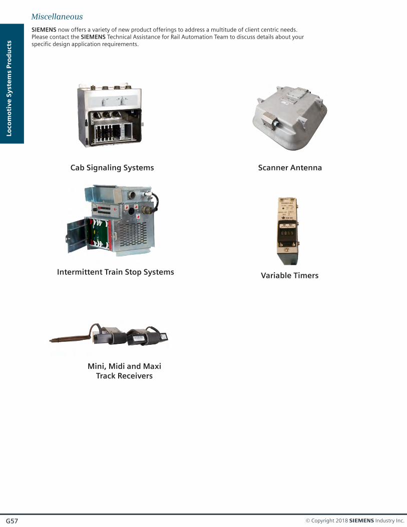
SIEMENS now offers a variety of new product offerings to address a multitude of client centric needs.Please contact the SIEMENS Technical Assistance for Rail Automation Team to discuss details about your specific design application requirements.
Cab Signaling Systems
Intermittent Train Stop Systems
Mini, Midi and MaxiTrack Receivers
Variable Timers
Scanner Antenna
Miscellaneous
G57
Lo
co
mo
tiv
e S
yst
em
s P
rod
ucts
© Copyright 2018 s Industry Inc.

G58
Lo
co
mo
tiv
e S
yst
em
s P
rod
ucts
SIE-RA-CMP-001-18-EN