logic and gates - wordpress.com · 2016-10-26 · logic and gates. 2 logic diagram: a graphical...
TRANSCRIPT

LOGIC AND GATES
2
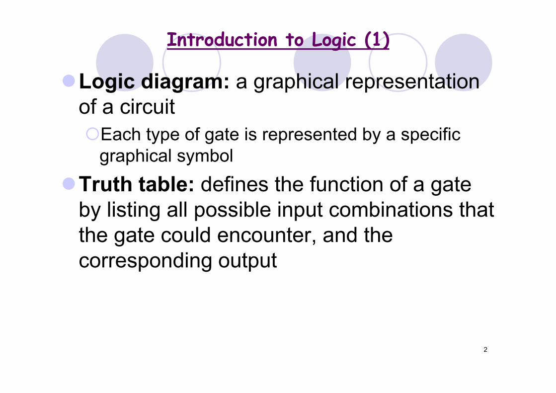
Logic diagram: a graphical representation of a circuit
Each type of gate is represented by a specific graphical symbol
Truth table: defines the function of a gate by listing all possible input combinations that the gate could encounter, and the corresponding output
Introduction to Logic (1)

3
Introduction to Logic (2)
• Many digital electronic processes aredesigned around “logic” circuits.
• The Inputs and Outputs in logic have only two values:• 0 & 1;• High & Low;• On & Off;• True and False.
• Logic is ideally suited to help designdigital electronic circuits because of its binary nature.
• We will look at some fundamental logic circuits.

4
Logic: Switches in Series
• The bulb will light only under certain conditions: what?
S1 S2
Complete the following:• The bulb will turn on only when switches S1 ___ S2 are
closed, for all other combinations the bulb is off.
S1 S2 Lit
0 0 00 1 01 0 01 1 1
5
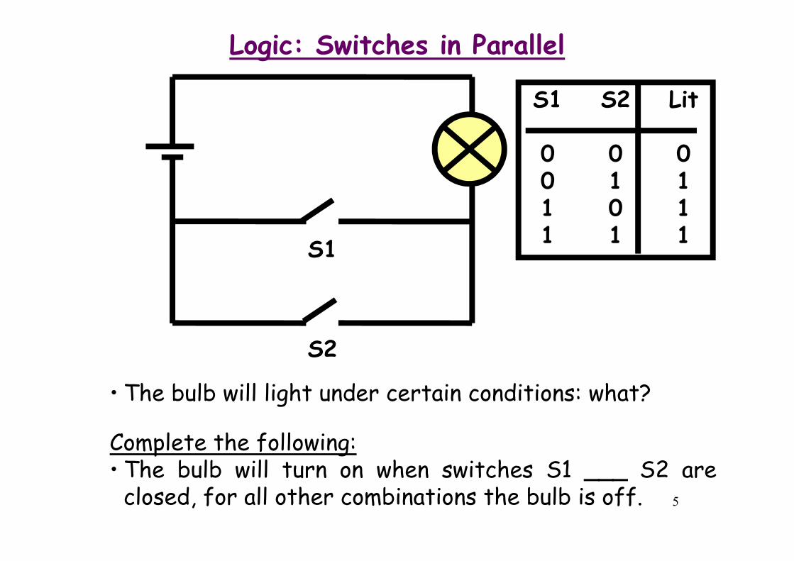
Logic: Switches in Parallel
S1
S2
• The bulb will light under certain conditions: what?
Complete the following:• The bulb will turn on when switches S1 ___ S2 are
closed, for all other combinations the bulb is off.
S1 S2 Lit
0 0 00 1 11 0 11 1 1
6
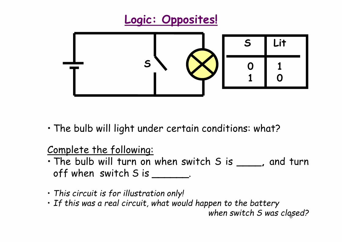
Logic: Opposites!
S
• The bulb will light under certain conditions: what?
Complete the following:• The bulb will turn on when switch S is ____, and turn
off when switch S is ______.
S Lit
0 11 0
• This circuit is for illustration only!• If this was a real circuit, what would happen to the battery
when switch S was closed?
7
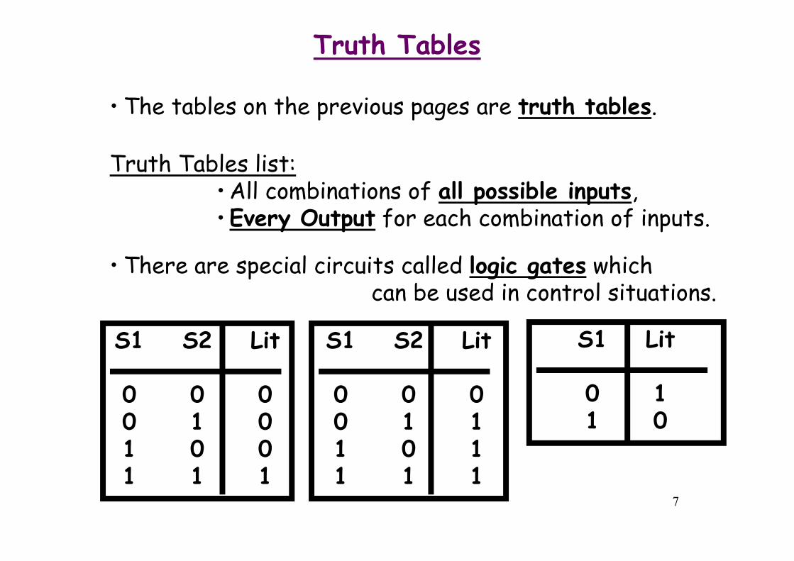
Truth Tables
• The tables on the previous pages are truth tables.
Truth Tables list:• All combinations of all possible inputs,•Every Output for each combination of inputs.
• There are special circuits called logic gates whichcan be used in control situations.
S1 S2 Lit
0 0 00 1 01 0 01 1 1
S1 S2 Lit
0 0 00 1 11 0 11 1 1
S1 Lit
0 11 0

8
CONSTRUCTING GATES

9
A gate is a device that performs a basic operation on electrical signals
Gates are combined into circuitsto perform more complicated tasks
10
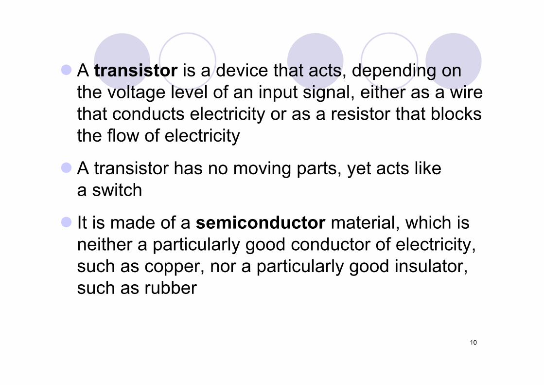
A transistor is a device that acts, depending on the voltage level of an input signal, either as a wire that conducts electricity or as a resistor that blocks the flow of electricity
A transistor has no moving parts, yet acts like a switch
It is made of a semiconductor material, which is neither a particularly good conductor of electricity, such as copper, nor a particularly good insulator, such as rubber
11
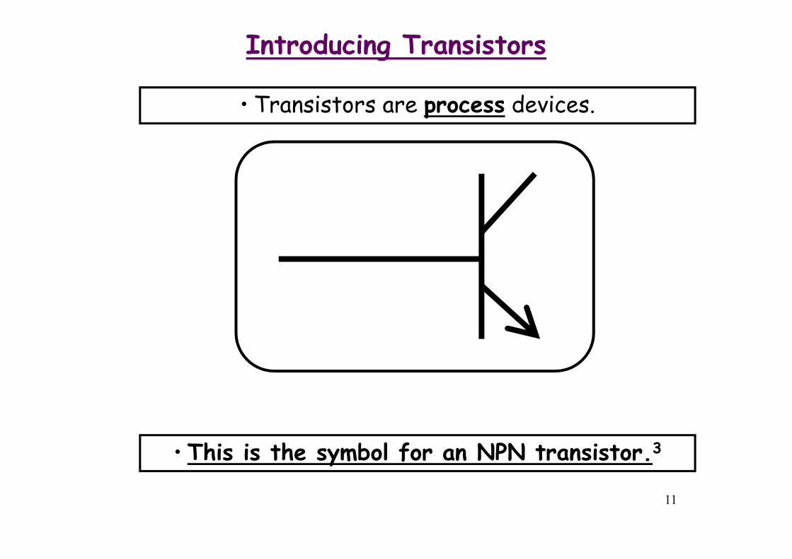
Introducing Transistors
• This is the symbol for an NPN transistor.3
• Transistors are process devices.

12
Transistor Terminals
• Transistors have three terminals:
Collector
Emitter
Base

13
Constructing Gates
• A transistor has three terminals
– A source
– A base
– An emitter, typically connected to a ground wire
• If the electrical signal is grounded, it is allowed to flow through an alternative route to the ground (literally) where it can do no harm
Figure 4.8 The connections of a transistor
14
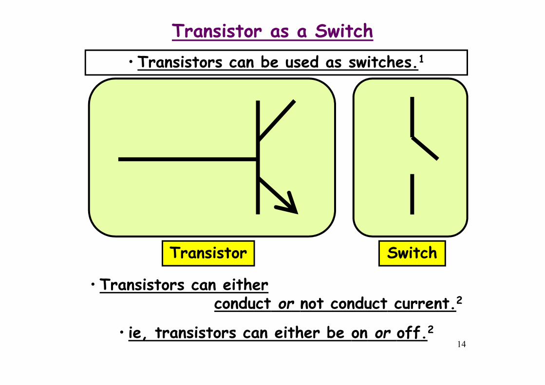
Transistor as a Switch
• Transistors can be used as switches.1
• Transistors can eitherconduct or not conduct current.2
• ie, transistors can either be on or off.2
Transistor Switch

15
How Transistors Work
• Switching iscontrolled bythe voltagebetween theBase and theEmitter.
Collector
Emitter
Base
• When VBE < 0.7V the transistor switches off andno current flows between the Collector and the Emitter.
• When VBE ≥ 0.7V the transistor switches on andcurrent flows between the Collector and the Emitter.
16
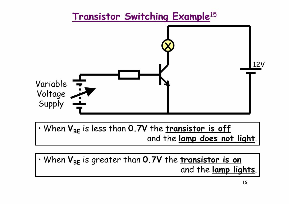
Transistor Switching Example15
• When VBE is less than 0.7V the transistor is offand the lamp does not light.
• When VBE is greater than 0.7V the transistor is onand the lamp lights.
X
VariableVoltageSupply
12V
17
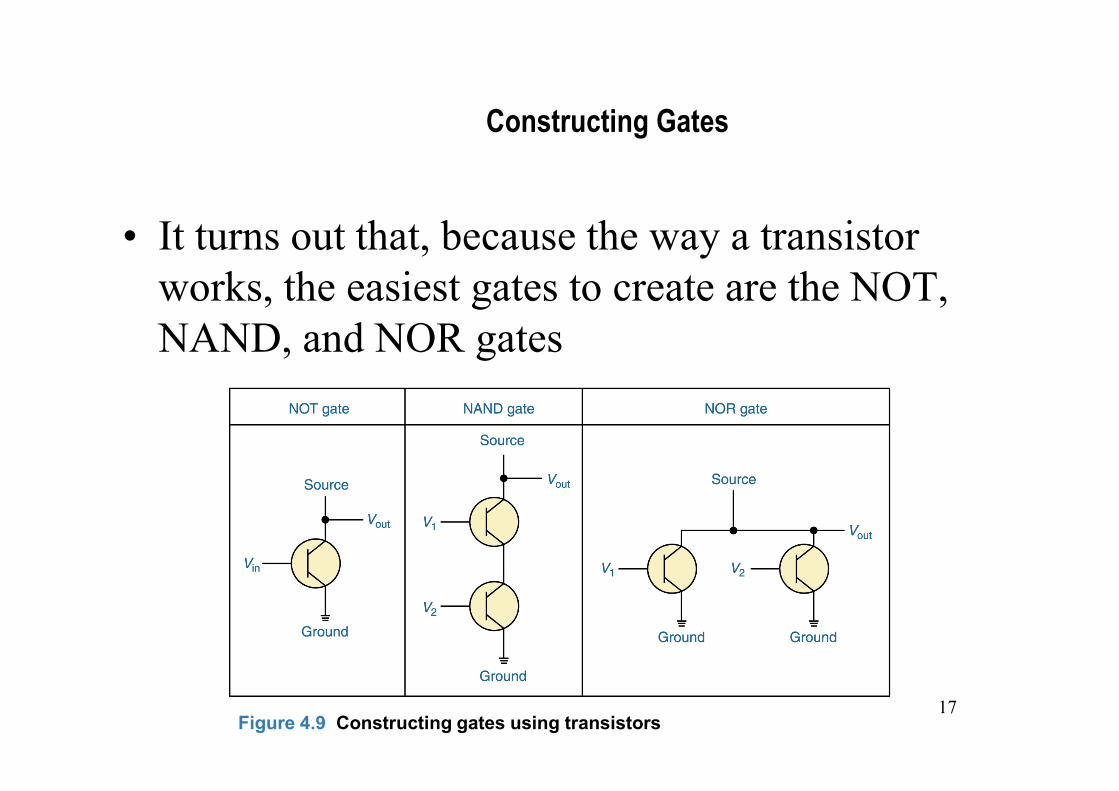
Constructing Gates
• It turns out that, because the way a transistor works, the easiest gates to create are the NOT, NAND, and NOR gates
Figure 4.9 Constructing gates using transistors
18
Gates
• Let’s examine the processing of the following six types of gates
– NOT
– AND
– OR
– XOR
– NAND
– NOR
• Typically, logic diagrams are black and white, and the gates are distinguished only by their shape

19
NOT Gate
• A NOT gate accepts one input value and produces one output value
Figure 4.1 Various representations of a NOT gate
20
NOT Gate
• By definition, if the input value for a NOT gate is 0, the output value is 1, and if the input value is 1, the output is 0
• A NOT gate is sometimes referred to as an inverter because it inverts the input value
21
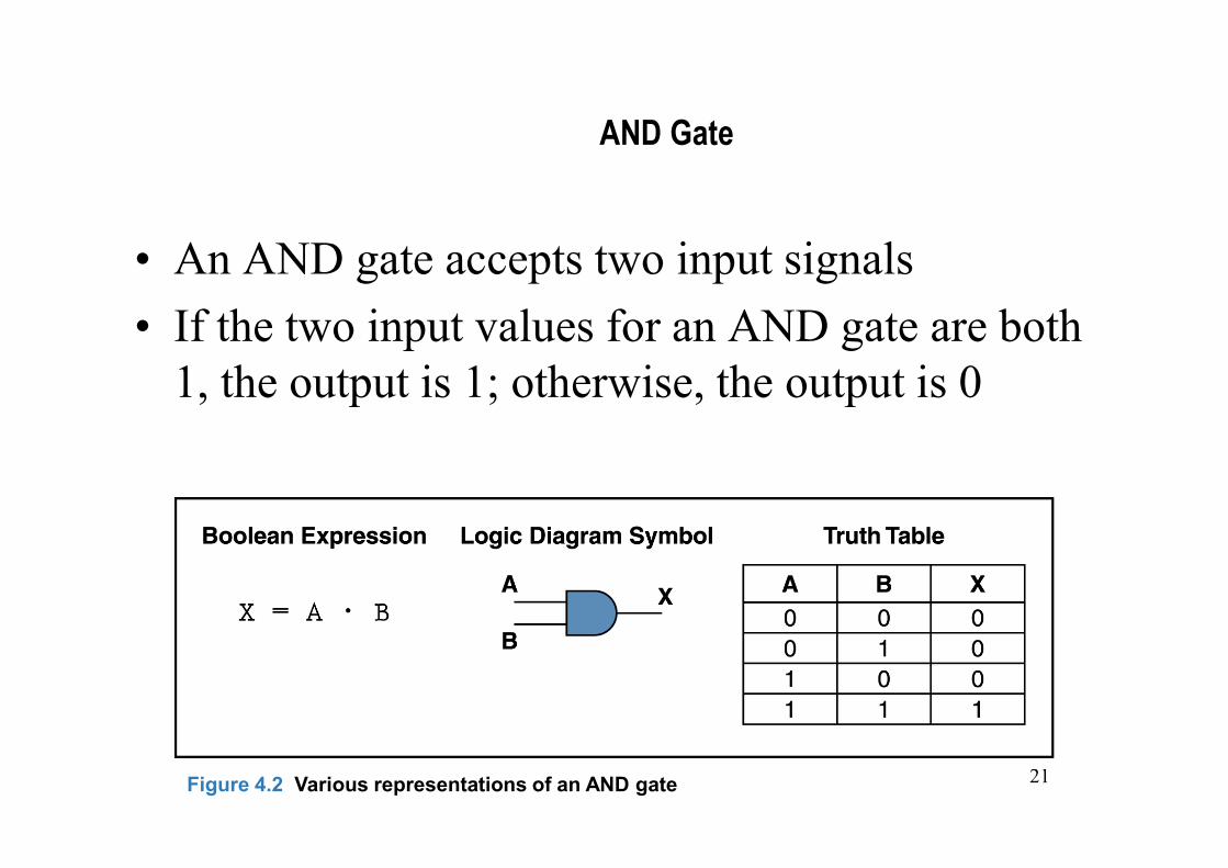
AND Gate
• An AND gate accepts two input signals
• If the two input values for an AND gate are both 1, the output is 1; otherwise, the output is 0
Figure 4.2 Various representations of an AND gate
22
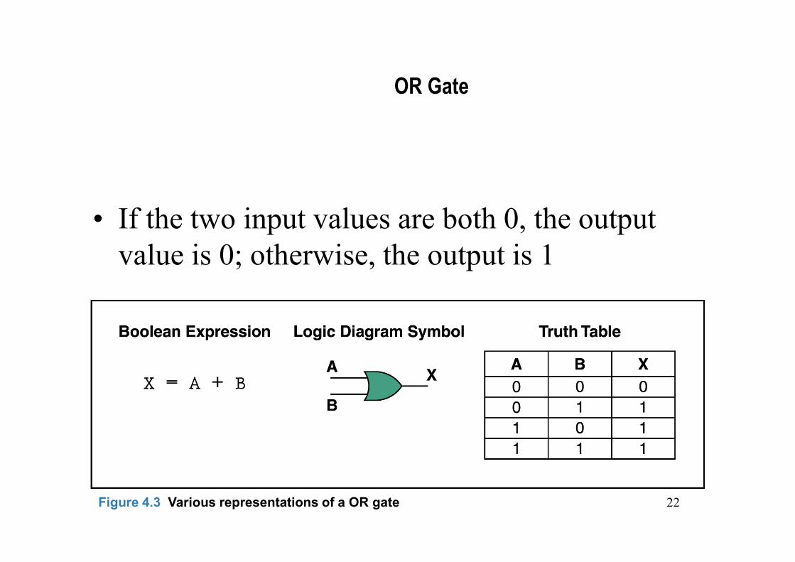
OR Gate
• If the two input values are both 0, the output value is 0; otherwise, the output is 1
Figure 4.3 Various representations of a OR gate

23
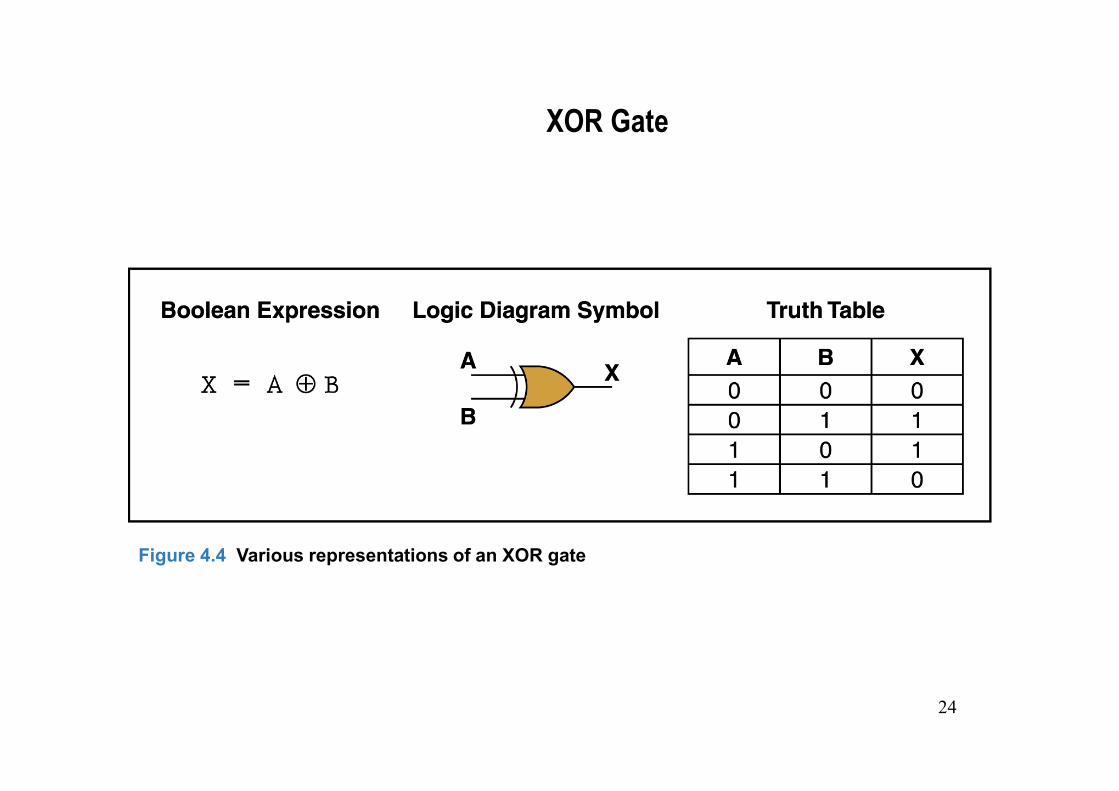
XOR Gate
• XOR, or exclusive OR, gate
– An XOR gate produces 0 if its two inputs are the same, and a 1 otherwise
– Note the difference between the XOR gate and the OR gate; they differ only in one input situation
– When both input signals are 1, the OR gate produces a 1 and the XOR produces a 0
24
XOR Gate
Figure 4.4 Various representations of an XOR gate

NAND and NOR Gates
• The NAND and NOR gates are essentially the opposite of the AND and OR gates, respectively
Figure 4.5 Various representations of a NAND gate
Figure 4.6 Various representations of a NOR gate
26
Review of Gate Processing
• A NOT gate inverts its single input value
• An AND gate produces 1 if both input values are 1
• An OR gate produces 1 if one or the other or both input values are 1

27
Review of Gate Processing (cont.)
• An XOR gate produces 1 if one or the other (but not both) input values are 1
• A NAND gate produces the opposite results of an AND gate
• A NOR gate produces the opposite results of an OR gate
28
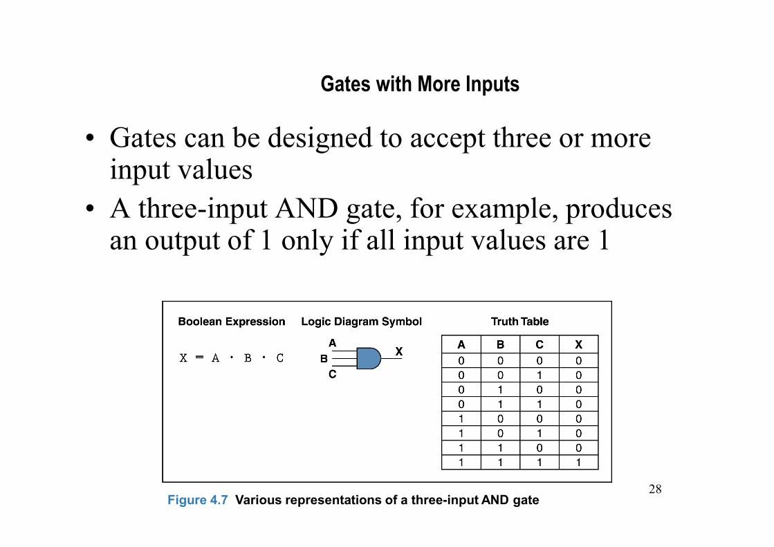
Gates with More Inputs
• Gates can be designed to accept three or more input values
• A three-input AND gate, for example, produces an output of 1 only if all input values are 1
Figure 4.7 Various representations of a three-input AND gate

29
Circuits
• Two general categories
– In a combinational circuit, the input values explicitly determine the output
– In a sequential circuit, the output is a function of the input values as well as the existing state of the circuit
• As with gates, we can describe the operations of entire circuits using three notations
– Boolean expressions
– logic diagrams
– truth tables

30
Combinational Circuits
• Gates are combined into circuits by using the output of one gate as the input for another
Page 99
31
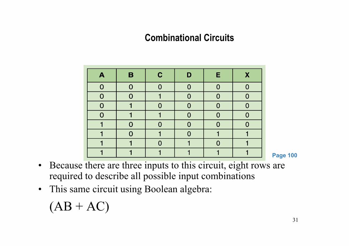
Combinational Circuits
• Because there are three inputs to this circuit, eight rows are required to describe all possible input combinations
• This same circuit using Boolean algebra:
(AB + AC)
Page 100

32

33
Now let’s go the other way; let’s take a Boolean expression and draw
• Consider the following Boolean expression: A(B + C)
Page 100
Page 101
• Now compare the final result column in this truth table to the truth table for the previous example
• They are identical
34
Now let’s go the other way; let’s take a Boolean expression and draw
• We have therefore just demonstrated circuit equivalence
– That is, both circuits produce the exact same output for each input value combination
• Boolean algebra allows us to apply provable mathematical principles to help us design logical circuits
35
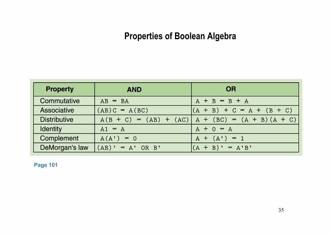
Properties of Boolean Algebra
Page 101