logic design - mcmaster universityshirani/2di4/chapter2.pdf · logic design chapter 2: ... • to...
TRANSCRIPT

Logic Design
Chapter 2: Introduction to Logic Circuits

Copyright S. Shirani
Introduction • Logic circuits perform operation on digital signal • Digital signal: signal values are restricted to a few discrete
values • Binary logic circuits: signals can have two values represented
by 0 and 1.
Copyright S. Shirani
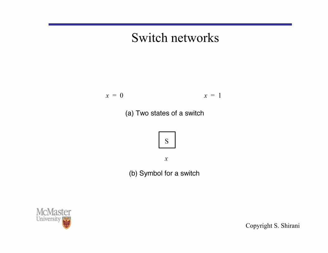
Switch networks

Copyright S. Shirani
Switch networks

Copyright S. Shirani
Switch networks

Copyright S. Shirani
Switch networks
S Light Power supply
R
x

Copyright S. Shirani
Logic Operations • The fundamental logic operations are:
• AND F = X.Y • OR F = X + Y • NOT F = X′ (complement) • Note: • X′ and are used interchangeably!

Copyright S. Shirani
Logic Operations • Don’t confuse the AND symbol (.) and OR symbol (+) with
arithmetic multiplication and addition • There are some differences: • Example:
– Arithmetic addition: 1+1=2 – OR operation: 1+1=1
• Based on the context you should recognize if it is AND/OR or addition/multiplication
• One more thing: sometimes we drop the . symbol • Example: a.b is the same as ab

Copyright S. Shirani
Truth table • The most basic representation of a logic function is a truth
table. • A truth table lists the output of the circuit for every
possible input combination. • There are 2n rows in a truth table for an n-variable function

Copyright S. Shirani
Logic Gate • Binary signals are manipulated using logic gates. These are
electronic devices whose inputs and outputs are interpreted with only two values, representing logic 0 and logic 1.
Copyright S. Shirani
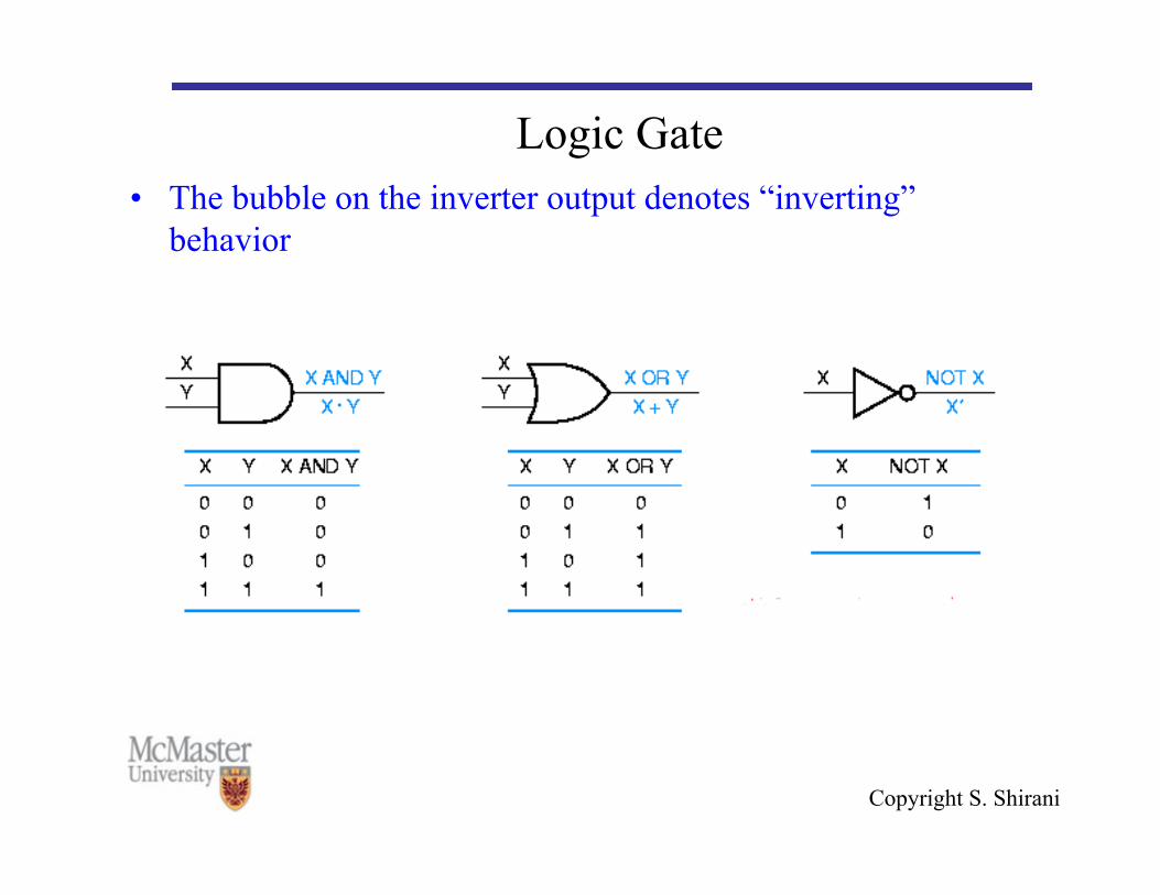
Logic Gate • The bubble on the inverter output denotes “inverting”
behavior

Copyright S. Shirani
Analysis and Synthesis of a Logic Network • Combinations of gates form a logic circuit or logic network • Analysis: For an existing network determine the function
performed by the network • Synthesis: Design a network that implements a desired
function

Copyright S. Shirani

Copyright S. Shirani
1 0
1 0
1 0
1 0
1 0
x 1
x 2
A
B
f Time
(c) Timing diagram

Copyright S. Shirani
1 1 0 0 → → → 0 0 1 1 → → →
1 1 0 1 → → → 0 1 0 1 → → → g
x 1
x 2
(d) Network that implements g x 1 x 2 + =
Copyright S. Shirani
Boolean Algebra • A variety of implementations are available for a logic function • How to find the best implementation?

Copyright S. Shirani
Boolean Algebra • To design logic circuits and describe their operation we use a
mathematical tool called Boolean algebra (from English mathematician George Boole in 1800’s) that operates on two-valued functions.

Copyright S. Shirani
Axioms of Boolean algebra The axioms (or postulates) of a mathematical system are a
minimal set of basic definitions that we assume to be true. The first three pairs of axioms state the formal definitions of
the AND (logical multiplication) and OR (logical addition) operations: (1a) 0·0 = 0 (1b) 1+1 = 1 (2a) 1·1 = 1 (2b) 0+0 = 0 (3a) 0·1 = 1·0 = 0 (3b) 1+0 = 0+1 = 1
The next axioms embody the complement notation: (4a) If X=0, then X’=1 (4b) If X=1, then X’=0

Copyright S. Shirani
Theorems of Boolean algebra Theorems are statements, known to be true, that allow us to
manipulate algebraic expressions to have simpler analysis or more efficient synthesis of the corresponding circuits.
Theorems involving a single variable: (5a) X·0 = 0 (5b) X+1 = 1 (Null elements)
(6a) X·1 = X (6b) X+0 = X (Identities) (7a) X·X = X (7b) X+X = X (Idempotency) (8a) X·X’ = 0 (8b) X+X’ = 1 (Complements)
(9) (X’)’ = X (Involution) • These theorems can be proved to be true. Let us prove 6b:
[X=0] 0+0=0 (true, according to 2b) [X=1] 1+0=1 (true, according to 3b)
Copyright S. Shirani
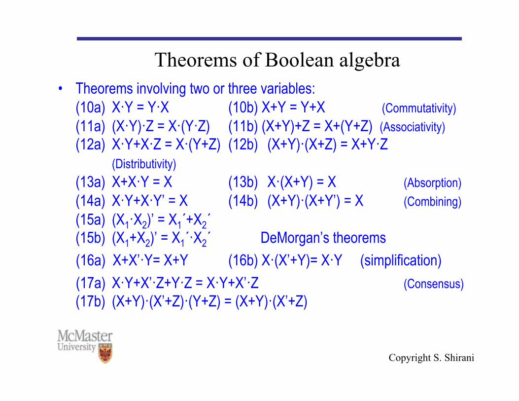
Theorems of Boolean algebra • Theorems involving two or three variables:
(10a) X·Y = Y·X (10b) X+Y = Y+X (Commutativity) (11a) (X·Y)·Z = X·(Y·Z) (11b) (X+Y)+Z = X+(Y+Z) (Associativity) (12a) X·Y+X·Z = X·(Y+Z) (12b) (X+Y)·(X+Z) = X+Y·Z
(Distributivity) (13a) X+X·Y = X (13b) X·(X+Y) = X (Absorption) (14a) X·Y+X·Y’ = X (14b) (X+Y)·(X+Y’) = X (Combining) (15a) (X1·X2)’ = X1´+X2´ (15b) (X1+X2)’ = X1´·X2´ DeMorgan’s theorems
(16a) X+X’·Y= X+Y (16b) X·(X’+Y)= X·Y (simplification) (17a) X·Y+X’·Z+Y·Z = X·Y+X’·Z (Consensus)
(17b) (X+Y)·(X’+Z)·(Y+Z) = (X+Y)·(X’+Z)

Copyright S. Shirani
Duality • Theorems were presented in pairs. • The b version of a theorem is obtained from the a version by
swapping “0” and “1”, and “·” and “+”. • Principle of Duality: Any theorem or identity in Boolean
algebra remains true if 0 and 1 are swapped and · and + are swapped throughout.
• Duality is important because it doubles the usefulness of everything about Boolean algebra and manipulation of logic functions.

Copyright S. Shirani
Consensus theorem

Copyright S. Shirani
Consensus theorem • Using duality:

Copyright S. Shirani
Boolean Algebra

Copyright S. Shirani
Boolean Algebra • Differences between Boolean and ordinary algebra: • Distributive law of + over . x+(y.z)=(x+y).(x+z) is not valid
in ordinary algebra • Boolean algebra does not have additive or multiplicative
inverse so there is no subtraction or division operations

Copyright S. Shirani
Boolean Algebra • Boolean algebra is used for manipulating logical functions
when designing digital hardware.
• However, today most design is done using Computer-Aided Design (CAD) software that includes schematic capture, logic simplification and simulation.
• Other methods include truth tables, Venn diagrams and Karnaugh Maps.
Copyright S. Shirani
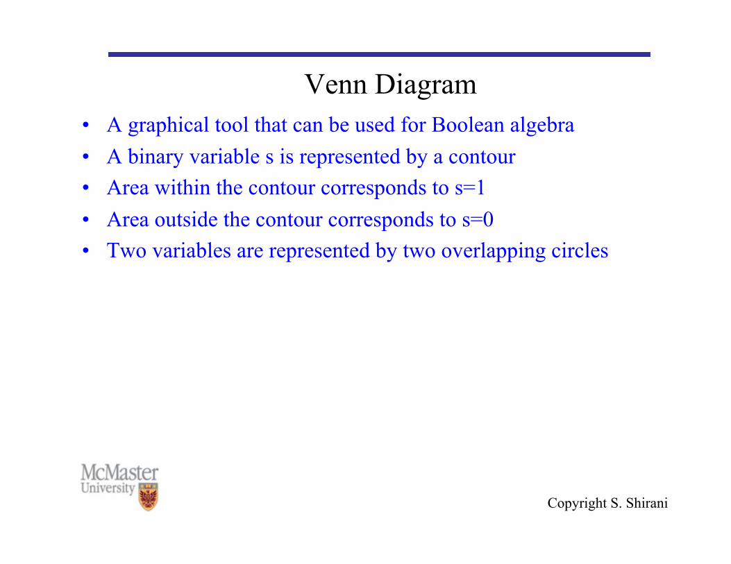
Venn Diagram • A graphical tool that can be used for Boolean algebra • A binary variable s is represented by a contour • Area within the contour corresponds to s=1 • Area outside the contour corresponds to s=0 • Two variables are represented by two overlapping circles

Copyright S. Shirani
Venn Diagram

Copyright S. Shirani
Venn Diagram

Copyright S. Shirani
Precedence of operations • In the absence of parentheses, operations in a logic expression
must be performed in the order: NOT, AND, OR • Example:

Copyright S. Shirani
Synthesis using AND, OR and NOT • One way of designing a logic circuit that implements a truth
table is to create a product term that has a value of 1 for each valuation for which the output function has to be 1.
• Then we take the logical sum of these product terms to realize f

Copyright S. Shirani

Copyright S. Shirani

Copyright S. Shirani
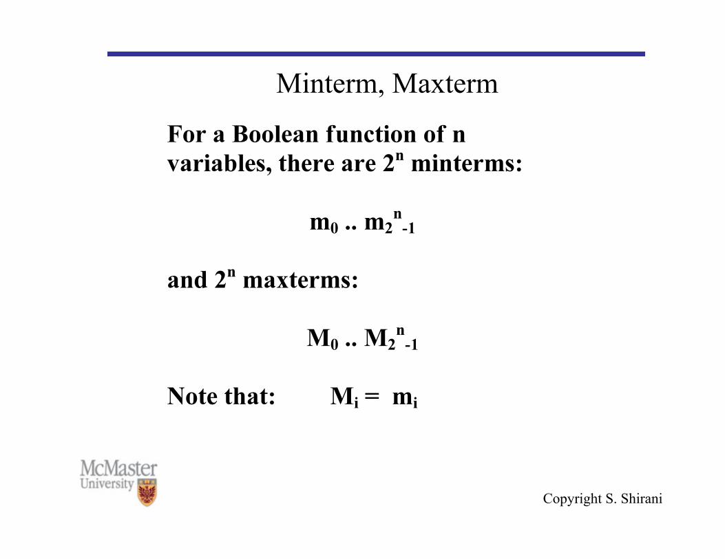
Minterm, Maxterm • Minterm • A product term in which all variables of a function appear
exactly once, uncomplemented or complemented.
• Maxterm • A sum term in which all variables of a function appear exactly
once, uncomplemented or complemented.
Copyright S. Shirani
Minterm, Maxterm

Copyright S. Shirani
Minterm, Maxterm
Copyright S. Shirani
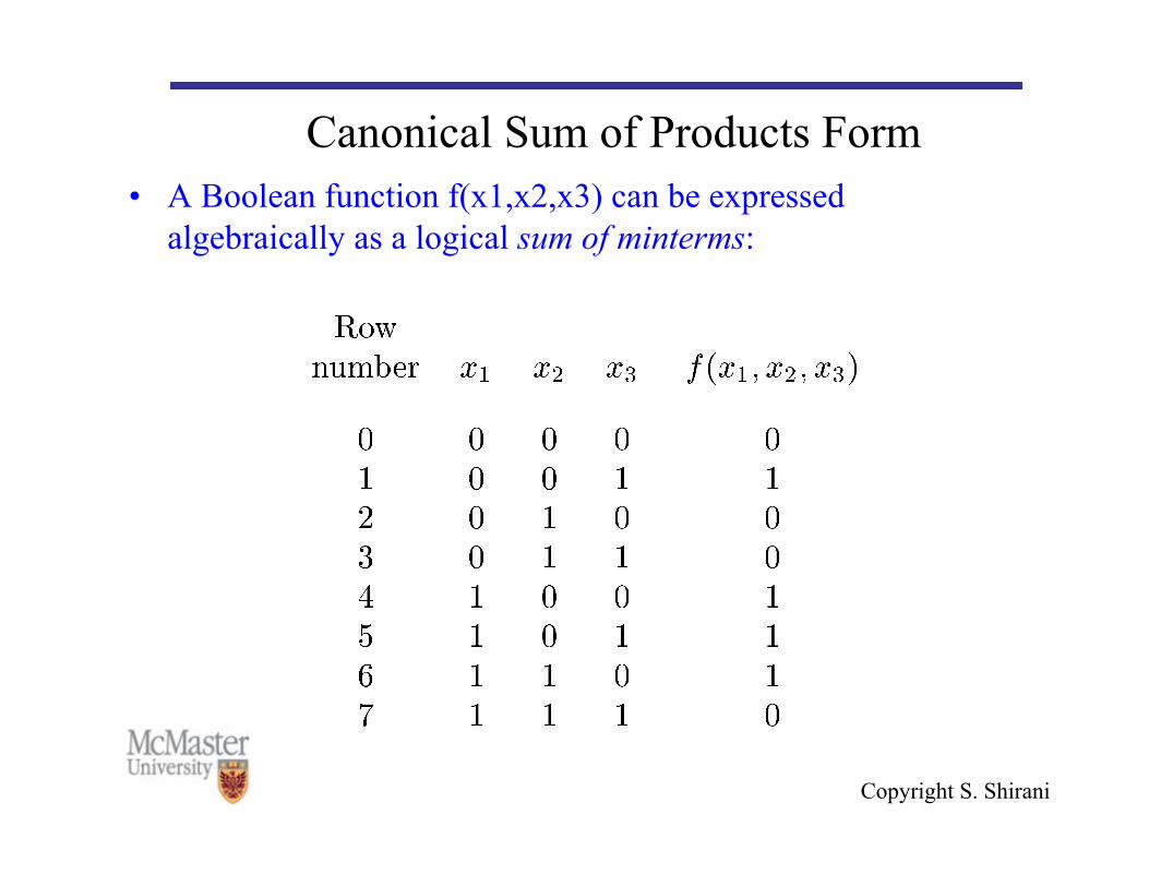
Canonical Sum of Products Form • A Boolean function f(x1,x2,x3) can be expressed
algebraically as a logical sum of minterms:

Copyright S. Shirani
Canonical Sum of Products Form • f can be expressed as sum of product terms (SOP)
Copyright S. Shirani
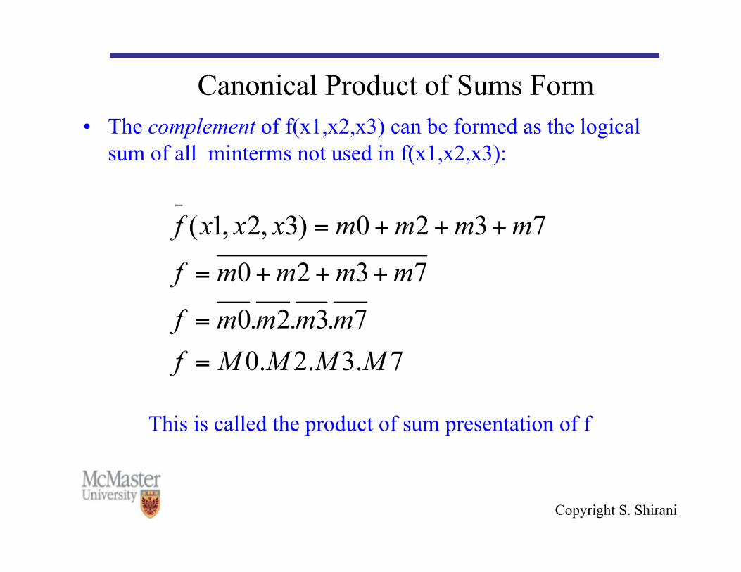
Canonical Product of Sums Form • The complement of f(x1,x2,x3) can be formed as the logical
sum of all minterms not used in f(x1,x2,x3):
This is called the product of sum presentation of f
Copyright S. Shirani
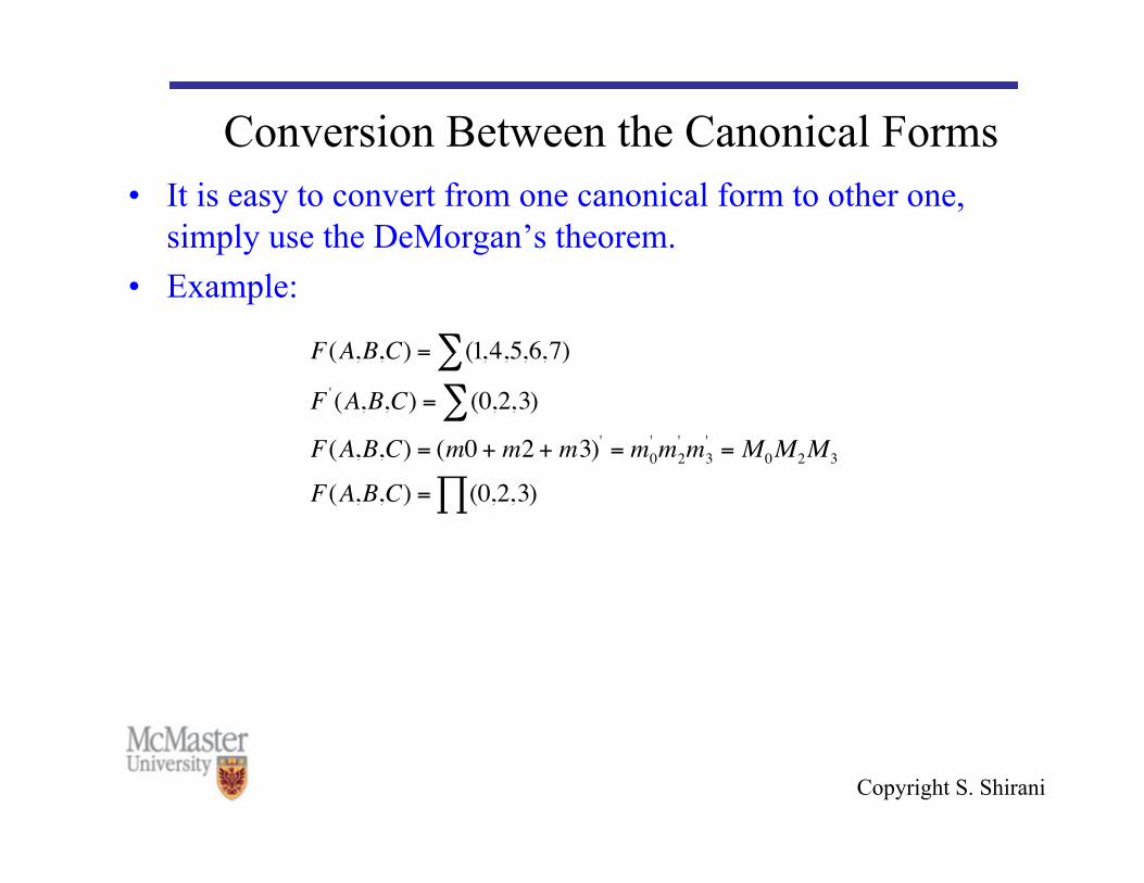
Conversion Between the Canonical Forms • It is easy to convert from one canonical form to other one,
simply use the DeMorgan’s theorem. • Example:
€
F(A,B,C) = (1,4,5,6,7)∑F ' (A,B,C) = (0,2,3)∑F(A,B,C) = (m0 + m2 + m3)' = m0
' m2' m3
' = M0M2M3
F(A,B,C) = (0,2,3)∏

Copyright S. Shirani
Cost of a Logic Circuit • Cost of a logic circuit: total number of gates plus total number
of inputs to all gates in the circuit • The canonical SOP and POS implementations described
before are not necessarily minimum cost • We can simplify them to obtain minimum-cost SOP and POS
circuits
Copyright S. Shirani
Reducing Cost • How can we simplify a logic function? • There are systematic approached for doing this (e.g.,
Karnaugh map) that we will learn later • The other way is to use theorems and properties of Boolean
algebra and do algebraic manipulations. • Do an example on the board.

Copyright S. Shirani
Reducing Cost • The simplified version of SOP is called minimal SOP • The simplified version of POS is called minimal POS • We cannot in general predict whether the minimal SOP
expression or minimal POS expression will result in the lowest cost.
• It is often useful to check both expressions to see which gives the best result.

Copyright S. Shirani
Other Logic Operations • NAND, • NOR, • XOR, • XNOR

Copyright S. Shirani
NAND • NAND: a combination of an AND gate followed by an
inverter.
• Symbol for NAND is • NAND gates have several interesting properties:
€
↑

Copyright S. Shirani
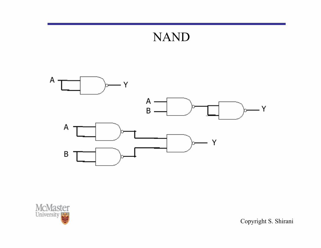
NAND • These three properties show that a NAND gate with both of
its inputs driven by the same signal is equivalent to a NOT gate
• A NAND gate whose output is complemented is equivalent to an AND gate, and a NAND gate with complemented inputs acts as an OR gate.
• Therefore, we can use a NAND gate to implement all three of the elementary operators (AND,OR,NOT).
• Therefore, ANY Boolean function can be constructed using only NAND gates.
Copyright S. Shirani
NAND
NOT Gate

Copyright S. Shirani
NOR • NOR: a combination of an OR gate followed by an inverter.
• NOR gates also have several interesting properties:

Copyright S. Shirani
NOR • Just like the NAND gate, any logic function can be
implemented using just NOR gates. • Both NAND and NOR gates are very valuable as any design
can be realized using either one. • It is easier to build an IC chip using all NAND or NOR gates
than to combine AND,OR, and NOT gates. • NAND/NOR gates are typically faster at switching and
cheaper to produce.

Copyright S. Shirani
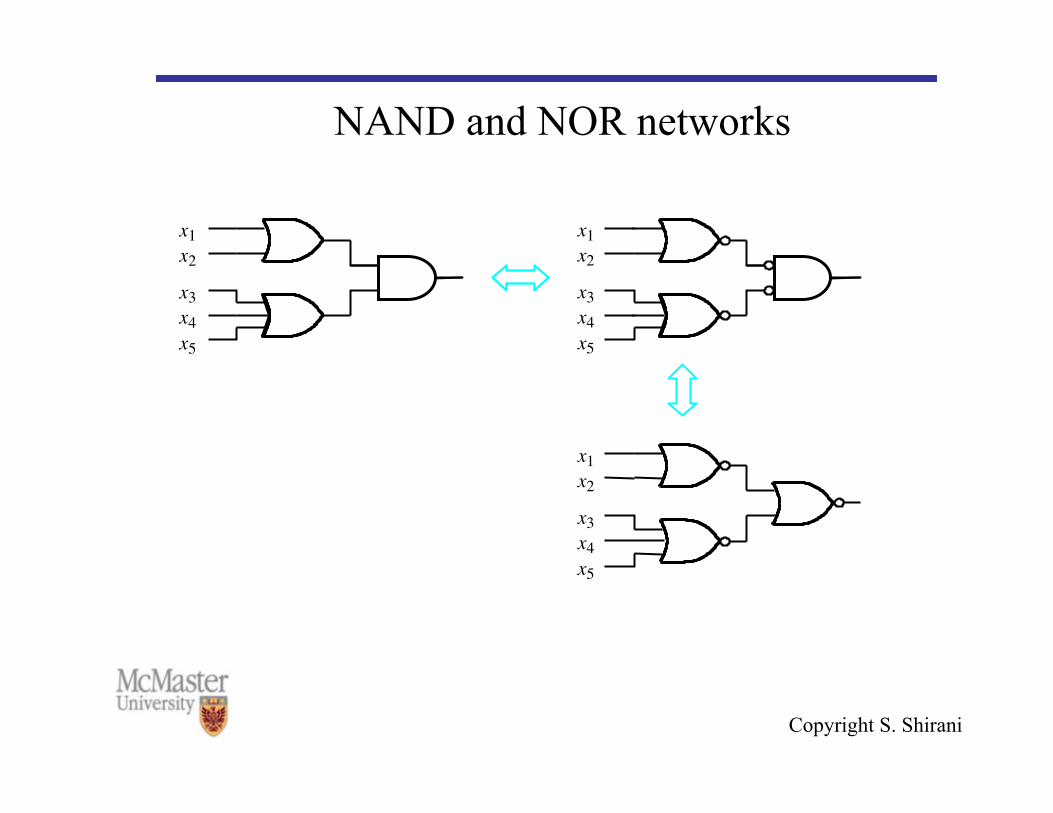
NAND and NOR networks • NAND and NOR can be implemented by simpler electronic
circuits than the AND and OR functions • Can these gates be used in synthesis of logic circuits?

Copyright S. Shirani
NAND and NOR networks
x 1 x 2
x 1 x 2
x 1 x 2
x 1 x 2
x 1 x 2
x 1 x 2
x 1 x 2 x 1 x 2 + = (a)
x 1 x 2 + x 1 x 2 = (b)

Copyright S. Shirani
NAND and NOR networks
x 1 x 2 x 3 x 4 x 5
x 1 x 2 x 3 x 4 x 5
x 1 x 2 x 3 x 4 x 5
Copyright S. Shirani
NAND and NOR networks
x 1 x 2 x 3 x 4 x 5
x 1 x 2 x 3 x 4 x 5
x 1 x 2 x 3 x 4 x 5
Copyright S. Shirani
Exclusive OR (XOR) • The eXclusive OR (XOR) function is an important Boolean
function used extensively in logic circuits. • The XOR function maybe:
– implemented directly as an electronic circuit (truly a gate) or – implemented by interconnecting other gate types (used as a
convenient representation) • The XOR function means:
X OR Y, but NOT BOTH
Copyright S. Shirani
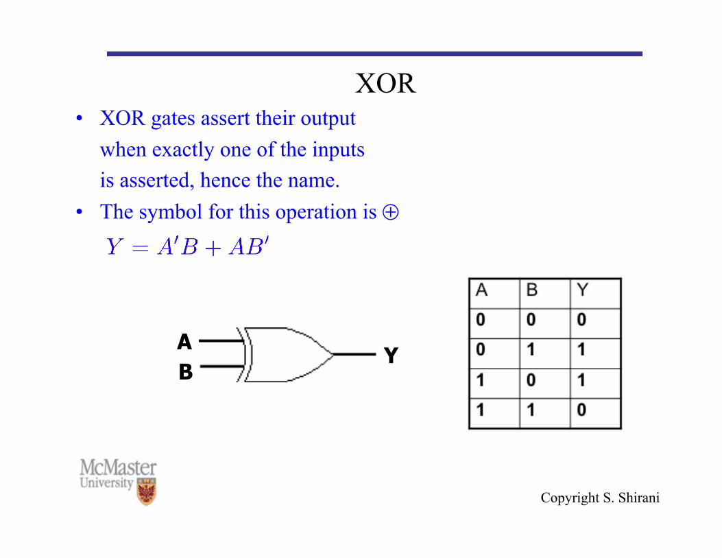
XOR • XOR gates assert their output
when exactly one of the inputs is asserted, hence the name.
• The symbol for this operation is ⊕
A B
Y

Copyright S. Shirani
XNOR • The eXclusive NOR function is the complement of the XOR
function • The symbol for this operation is , i.e.
1 1 = 1 and 1 0 = 0.
• Why is the XNOR function also known as the equivalence function?

Copyright S. Shirani
XOR Implementations • A SOP implementation
• A NAND implementation

Copyright S. Shirani
XOR and XNOR • Uses for the XOR and XNORs gate include:
– Adders/subtractors/multipliers – Counters/incrementers/decrementers – Parity generators/checkers

Copyright S. Shirani
XOR • XOR identities:

Copyright S. Shirani
Gates with more than two inputs • A gate can be extended to have multiple inputs if the binary
operation it represents is commutative and associative. • AND and OR operations have these two properties • NAND and NOR are not associative:

Copyright S. Shirani
Gates with more than two inputs • We define multiple input NAND and NOR gates as follows:
Copyright S. Shirani
Gates with more than two inputs • XOR and XNOR are both commutative and associative • Definition of XOR should be modified for more than two
inputs • For more than 2 inputs, XOR is called an odd function: it is
equal to 1 if the input variables have an odd number of 1’s • Similarly, for more than 2 inputs, XNOR is called an even
function: it is equal to 1 if the input variables have an even number of 1’s

Copyright S. Shirani
Learning Objectives • List the three basic logic operations • Draw the truth table for the basic logic operations • Build truth table for an arbitrary number of variables • Draw schematic for basic logic gates • Perform analysis on simple logic circuits • Draw timing diagram for simple logic circuits