logic scanner user manual - blunk electronic€¦ · product brief logic scanner please read...
TRANSCRIPT

PRODUCT BRIEF
Logic Scanner
Please read carefully before power up !
Doc. Version 201610281
Author: Mario Blunk
Blunk electronic at www.blunkelectronic.de 1

Preface
When debugging complex digital electronic hardware a set of several devices like oscilloscope, logic analyzer, pattern detector, pulse generator, pulse detector and the like is required.
The Logic Scanner combines these devices reducing equipment space and investment.
This device has been developed from hardware developers for hardware developers.
It gives only relevant information to the operator required to get the job done, reducing the data flow toward the engineers mind dramatically.
The Logic Scanner is operated via keystrokes on a PC connected to the device. The device itself does not require any driver installation and thus runs operating system independent.
The device comes with a 19 inch chassis housing with 1 RU as shown on Image 1. Common oscilloscope probes can be plugged on the BNC sockets on the front panel to feed in signal, clock and trigger signals.
2 Blunk electronic at www.blunkelectronic.de
Image 1: Logic Scanner

Table of Contents 1 Device Features Overview.................................................................................................4 2 Device Operation Overview...............................................................................................5 3 Operating Modes................................................................................................................7
3.1 Level & Pulse Detection..............................................................................................7 3.2 Input Channel Selection..............................................................................................8 3.3 Input Termination........................................................................................................9 3.4 Input Filters...............................................................................................................10 3.5 Signal Driver.............................................................................................................11 3.6 Trace Memory...........................................................................................................13
3.6.1 Manual Trigger Mode........................................................................................16 3.6.2 External Trigger Mode.......................................................................................18
3.6.2.1 OneShot tracing........................................................................................19 3.6.2.2 Repetitive tracing.......................................................................................20
3.7 Debugging Serial Buses...........................................................................................21 3.7.1 JTAG / IEEE 1149.x / Boundary Scan..............................................................21 3.7.2 I²C......................................................................................................................23
3.8 Saving Configuration................................................................................................23 4 Keystrokes Reference Table............................................................................................24 5 RS232 and Terminal Program of the Host Computer......................................................27
5.1 USBtoRS232Adapters..........................................................................................28 6 Useful Links......................................................................................................................30 7 Disclaimer........................................................................................................................30
Blunk electronic at www.blunkelectronic.de 3
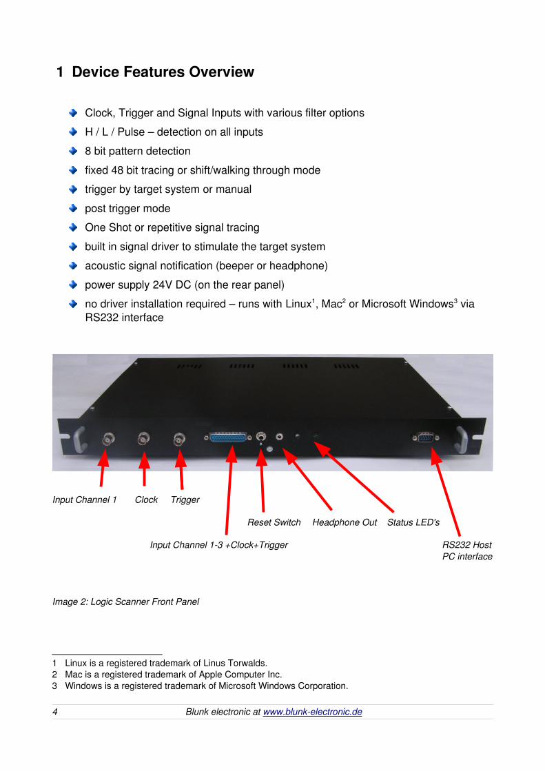
1 Device Features Overview
Clock, Trigger and Signal Inputs with various filter options
H / L / Pulse – detection on all inputs
8 bit pattern detection
fixed 48 bit tracing or shift/walking through mode
trigger by target system or manual
post trigger mode
One Shot or repetitive signal tracing
built in signal driver to stimulate the target system
acoustic signal notification (beeper or headphone)
power supply 24V DC (on the rear panel)
no driver installation required – runs with Linux1, Mac2 or Microsoft Windows3 via RS232 interface
1 Linux is a registered trademark of Linus Torwalds.2 Mac is a registered trademark of Apple Computer Inc.3 Windows is a registered trademark of Microsoft Windows Corporation.
4 Blunk electronic at www.blunkelectronic.de
Input Channel 1 Clock Trigger
Reset Switch Headphone Out Status LED's
Input Channel 13 +Clock+Trigger RS232 HostPC interface
Image 2: Logic Scanner Front Panel

2 Device Operation OverviewImage 3 gives a schematic of how to connect the Logic Scanner with the target hardware or the UUT (Unit Under Test) and the host PC.
Beside the signal of interest the target system must provide a trigger and a clock signal. The trigger is used in order to initiate signal tracing which in turn is synchronized by the system clock.
A definable 8 bit pattern can be detected in the signal data stream both visual or audible.
Read more on the trace memory modes in section 3.6 on page 13.
Further on, all inputs provide a level detector and a pulse detector which is useful to findvery short signal spikes. Input signals may be routed through SchmittTriggers or level detectors in order to filter out noise. Please find details in section 3.1 and 3.4.
There is also the possibility to activate an input termination resistor of 300 Ohms each in case signal integrity is an issue. Read more in section 3.3 page 9.
Blunk electronic at www.blunkelectronic.de 5
Image 3: Device Operation
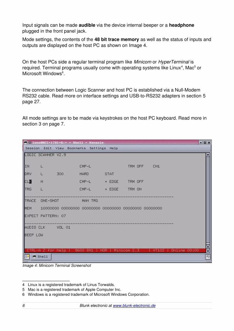
Input signals can be made audible via the device internal beeper or a headphone plugged in the front panel jack.
Mode settings, the contents of the 48 bit trace memory as well as the status of inputs andoutputs are displayed on the host PC as shown on Image 4.
On the host PCs side a regular terminal program like Minicom or HyperTerminal is required. Terminal programs usually come with operating systems like Linux4, Mac5 or Microsoft Windows6.
The connection between Logic Scanner and host PC is established via a NullModem RS232 cable. Read more on interface settings and USBtoRS232 adapters in section 5 page 27.
All mode settings are to be made via keystrokes on the host PC keyboard. Read more in section 3 on page 7.
4 Linux is a registered trademark of Linus Torwalds.5 Mac is a registered trademark of Apple Computer Inc.6 Windows is a registered trademark of Microsoft Windows Corporation.
6 Blunk electronic at www.blunkelectronic.de
Image 4: Minicom Terminal Screenshot
3 Operating Modes
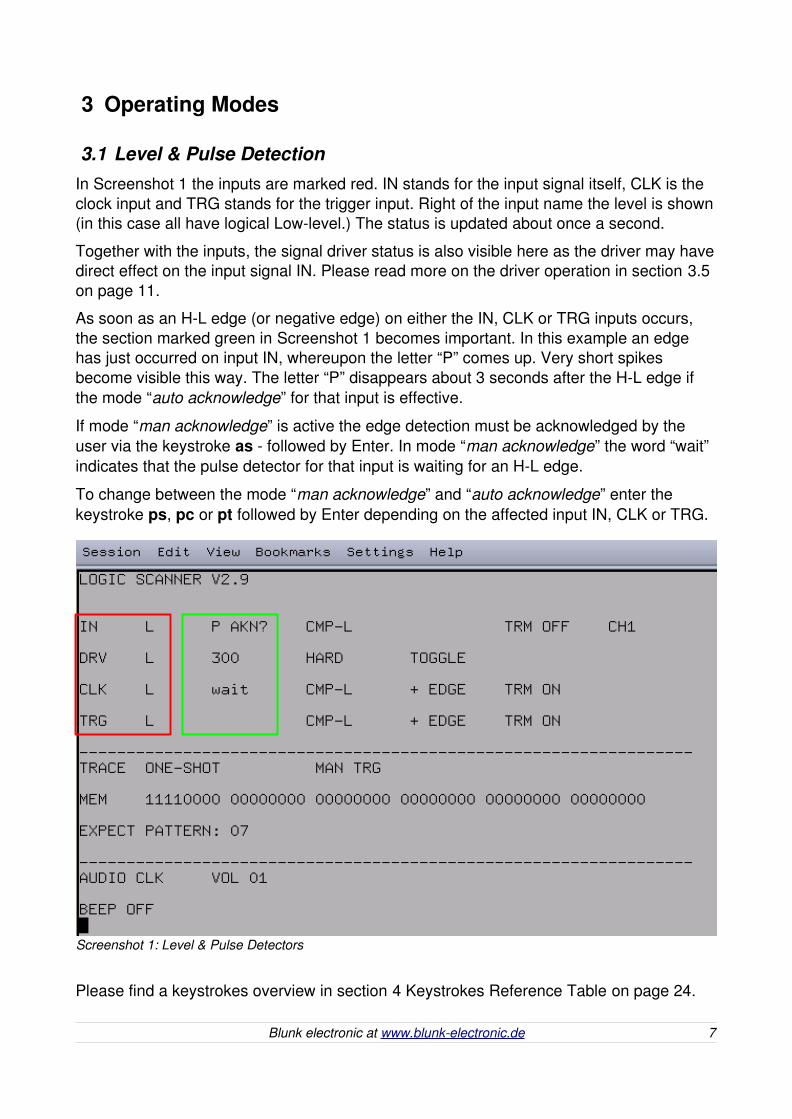
3.1 Level & Pulse DetectionIn Screenshot 1 the inputs are marked red. IN stands for the input signal itself, CLK is the clock input and TRG stands for the trigger input. Right of the input name the level is shown(in this case all have logical Lowlevel.) The status is updated about once a second.
Together with the inputs, the signal driver status is also visible here as the driver may havedirect effect on the input signal IN. Please read more on the driver operation in section 3.5 on page 11.
As soon as an HL edge (or negative edge) on either the IN, CLK or TRG inputs occurs, the section marked green in Screenshot 1 becomes important. In this example an edge has just occurred on input IN, whereupon the letter “P” comes up. Very short spikes become visible this way. The letter “P” disappears about 3 seconds after the HL edge if the mode “auto acknowledge” for that input is effective.
If mode “man acknowledge” is active the edge detection must be acknowledged by the user via the keystroke as followed by Enter. In mode “man acknowledge” the word “wait” indicates that the pulse detector for that input is waiting for an HL edge.
To change between the mode “man acknowledge” and “auto acknowledge” enter the keystroke ps, pc or pt followed by Enter depending on the affected input IN, CLK or TRG.
Please find a keystrokes overview in section 4 Keystrokes Reference Table on page 24.
Blunk electronic at www.blunkelectronic.de 7
Screenshot 1: Level & Pulse Detectors
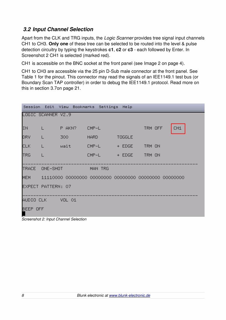
3.2 Input Channel SelectionApart from the CLK and TRG inputs, the Logic Scanner provides tree signal input channelsCH1 to CH3. Only one of these tree can be selected to be routed into the level & pulse detection circuitry by typing the keystrokes c1, c2 or c3 each followed by Enter. InScreenshot 2 CH1 is selected (marked red).
CH1 is accessible on the BNC socket at the front panel (see Image 2 on page 4).
CH1 to CH3 are accessible via the 25 pin DSub male connector at the front panel. SeeTable 1 for the pinout. This connector may read the signals of an IEE1149.1 test bus (or Boundary Scan TAP controller) in order to debug the IEE1149.1 protocol. Read more on this in section 3.7on page 21.
8 Blunk electronic at www.blunkelectronic.de
Screenshot 2: Input Channel Selection
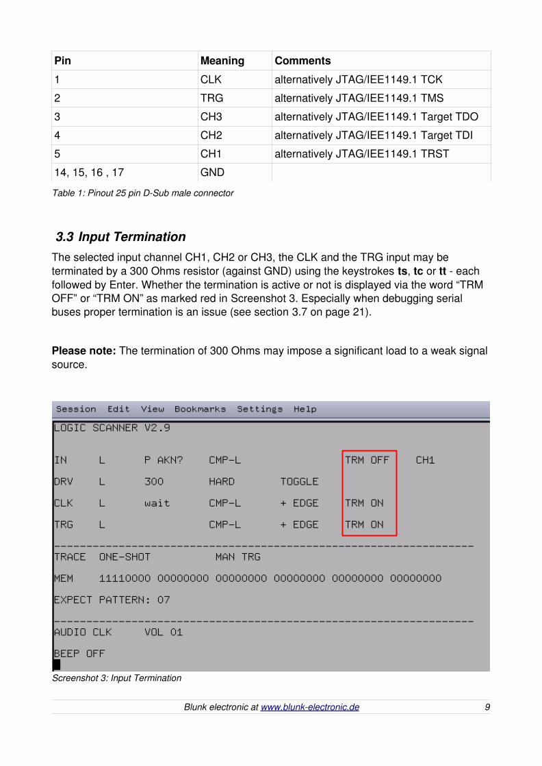
Pin Meaning Comments
1 CLK alternatively JTAG/IEE1149.1 TCK
2 TRG alternatively JTAG/IEE1149.1 TMS
3 CH3 alternatively JTAG/IEE1149.1 Target TDO
4 CH2 alternatively JTAG/IEE1149.1 Target TDI
5 CH1 alternatively JTAG/IEE1149.1 TRST
14, 15, 16 , 17 GND
Table 1: Pinout 25 pin DSub male connector
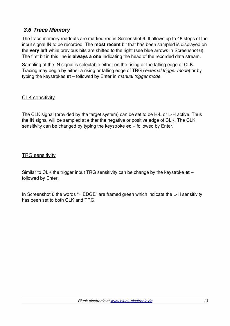
3.3 Input TerminationThe selected input channel CH1, CH2 or CH3, the CLK and the TRG input may be terminated by a 300 Ohms resistor (against GND) using the keystrokes ts, tc or tt each followed by Enter. Whether the termination is active or not is displayed via the word “TRM OFF” or “TRM ON” as marked red in Screenshot 3. Especially when debugging serial buses proper termination is an issue (see section 3.7 on page 21).
Please note: The termination of 300 Ohms may impose a significant load to a weak signalsource.
Blunk electronic at www.blunkelectronic.de 9
Screenshot 3: Input Termination

3.4 Input FiltersThe selected input channel CH1, CH2 or CH3, the CLK and the TRG input may be filtered via a H or Lsensitive comparator (CMPL / CMPH), a SchmittTrigger or not at all. InScreenshot 4 the current filter settings are marked red. To change the filter, type the keystrokes fs, fc and ft followed by Enter.
Filter properties:
CMPL : The input is interpreted as logical Low if the voltage drops below 0.8V. Otherwise the input is interpreted as logical High.
CMPH : The input is interpreted as logical High if the voltage exceeds 2.1V. Otherwise the input is interpreted as logical Low.
ST : Upper threshold voltage: 1.96V / lower threshold voltage 0.79V / hysteresis 1.17V
FLT OFF : Input is interpreted according to the LVTTL—Low Voltage TTL Std.
10 Blunk electronic at www.blunkelectronic.de
Screenshot 4: Input Filters

3.5 Signal DriverThe Signal Driver may be used in order to stimulate the target system by back driving into the selected input signal. While watching the level changes of the driver and the selected input channel it is possible to identify a floating net in the target system.
WARNING: When using the signal driver, make sure the target system does not suffer damage nor behave so that secondary damage may occur.
Screenshot 5 shows an example of a possible driver configuration. The relevant driver information is marked red here: The driver drives a statical logical H (appr. 3.0V) via a series resistor of 300 Ohms into the target.
The driver strength can be changed via the keystrokes ds0, ds1, ds2 and ds3 followed by Enter. Read more on the driver strength values in reference table in section 4 on page24.
Note: If driver strength ds1, ds2 or ds3 is active, the left status LED on the front panel flashes yellow notifying the operator that the Logic Scanner is driving into the target system.
To switch between statical logical H and L (appr. 0.2V) from the driver use the keystroke dv. Instead of a static output, a 1Hz toggling of the driver output can be obtained by the keystroke dt. Whether static or toggle mode is active is displayed by the words “STAT” or “TOGGLE” (see Screenshot 5).
The driver output may be set to characteristic pushpull, weak0, weak1 or highz using the keystroke do followed by Enter. The example shown in Screenshot 5 has the driver set in pushpull mode indicated by the word “HARD”.
Please look up the keystrokes reference table in section 4 on page 24 for more.
Blunk electronic at www.blunkelectronic.de 11

12 Blunk electronic at www.blunkelectronic.de
Screenshot 5: Signal Driver
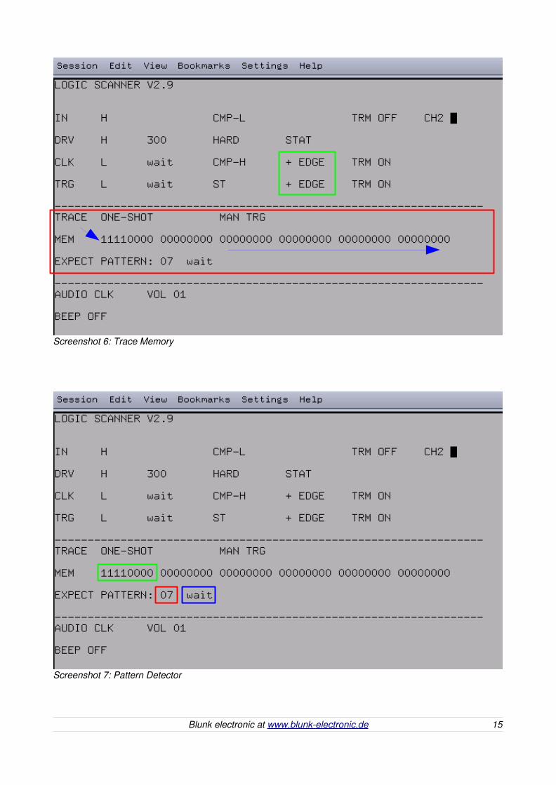
3.6 Trace MemoryThe trace memory readouts are marked red in Screenshot 6. It allows up to 48 steps of theinput signal IN to be recorded. The most recent bit that has been sampled is displayed onthe very left while previous bits are shifted to the right (see blue arrows in Screenshot 6). The first bit in this line is always a one indicating the head of the recorded data stream.
Sampling of the IN signal is selectable either on the rising or the falling edge of CLK. Tracing may begin by either a rising or falling edge of TRG (external trigger mode) or by typing the keystrokes st – followed by Enter in manual trigger mode.
CLK sensitivity
The CLK signal (provided by the target system) can be set to be HL or LH active. Thus the IN signal will be sampled at either the negative or positive edge of CLK. The CLK sensitivity can be changed by typing the keystroke ec – followed by Enter.
TRG sensitivity
Similar to CLK the trigger input TRG sensitivity can be change by the keystroke et – followed by Enter.
In Screenshot 6 the words “+ EDGE” are framed green which indicate the LH sensitivity has been set to both CLK and TRG.
Blunk electronic at www.blunkelectronic.de 13

Pattern detector
The pattern detector watches the first 8 bit of the trace memory (marked green inScreenshot 7 on page 15) by comparing them continuously with the expect value (marked red in Screenshot 7 on page 15) set by the keystroke ex.
Please find an example of how to enter the expect value in section 4 on page 25.
Depending on the pattern acknowledge mode, the status of the pattern detector is indicated by the words “wait” , “MATCH” or “MATCH AKN?” (framed blue in Screenshot 7 on page 15).
Between the pattern acknowledge modes manual acknowledge and auto acknowledge can be changed by the keystroke pd – followed by Enter.
Manual Acknowledge Mode:
If no match has occurred yet, the status is “wait”.
If a match has occurred, the status changes to “MATCH ACN?”. This way the operator is requested to confirm the pattern match by the keystroke am whereupon the status changes back to “wait”.
Auto Acknowledge Mode:
If no match has occurred yet, no status is displayed.
If a match has occurred, the status changes to “MATCH” for about 3 seconds.
14 Blunk electronic at www.blunkelectronic.de
Blunk electronic at www.blunkelectronic.de 15
Screenshot 6: Trace Memory
Screenshot 7: Pattern Detector

3.6.1 Manual Trigger Mode
To activate this mode type the keystroke tr – followed by Enter. In Screenshot 8 the word “MAN TRG” is framed red which indicates that the manual trigger mode is active.
This mode is useful in situations where no trigger signal is available. In this mode the TRG input is ignored all the time. TRG does not affect the tracing here.
By typing the keystroke st the trace memory is reset. The first bit on the very left is automatically set to 1 whereas all other 47 bits get cleared.
As soon as an edge on the CLK input occurs the memory contents shift one step to the right while the position on the very left displays the IN bit sampled at that very moment.
After 48 bits have been read in the word “END” on the very right indicates that the tracing has come to an end or in other words the memory is full (marked green in Screenshot 8).
To record more than 48 bits the Rollmode may be used.
16 Blunk electronic at www.blunkelectronic.de
Screenshot 8: Manual Trigger Mode

ROLL mode
The keystroke ro – followed by Enter activates the Rollmode. Marked red in Screenshot 9the word “ROLL” indicates that this mode is active.
In this mode the data stream recording does not end at bit no. 48. Instead the visible datais shifted permanently to the right with each CLK edge.
If the CLK frequency is less than 1Hz or the target system is operated in single step mode,the data shifting is comfortable to watch with the naked eye.
Type ro – followed by Enter again to disable the Rollmode.
Note: Even if a certain succession of bits passes through the memory – into the void on the very right – it can still be detected using the pattern detector. The pattern detector tracks the whole datastream. Read more on page 14.
Blunk electronic at www.blunkelectronic.de 17
Screenshot 9: Roll Mode

3.6.2 External Trigger Mode
To activate this mode type the keystroke tr – followed by Enter. In Screenshot 10 the word“EXT TRG” is framed red which indicates that the external trigger mode is active.
This mode is useful if a trigger signal can be derived from the target system and fed into the TRG input of the Logic Scanner. This way the recording of the data stream starts at a certain and definable point of time.
By typing the keystroke st – followed by Enter the trace memory is reset. The trace memory indicates it is waiting for an edge on the TRG input by the word “READY” (markedgreen on Screenshot 10).
As soon as an edge on the CLK input occurs the memory contents shift one step to the right while the position on the very left displays the IN bit sampled at that very moment.
After 48 bits have been read in the word “END” on the very right indicates that the tracing has come to an end or in other words the memory is full (marked green in Screenshot 8).
To record more than 48 bits the Rollmode may be used. Please read more on page 17.
18 Blunk electronic at www.blunkelectronic.de
Screenshot 10: External Trigger Mode

Trigger delay
In order to let some external trigger events pass by before the actual tracing begins, a prescaler is provided. The prescaler counts the trigger edges until a given (hex)number ranging from 0 to F (in decimal 0 to 15) has been reached. The delay value is marked bluein Screenshot 10. It is set by the keystroke td . Please find an example of how to set the delay value in section 4on page 26.
If the delay value is set to 00h the trigger signal TRG undergoes no delay.
3.6.2.1 OneShot tracing
By typing the keystroke tm the trace mode can be changed to OneShottracing . The terminal screen indicates this mode by the word “ONESHOT” as marked red inScreenshot 11.
In this mode the data stream gets recorded only once following a trigger event. As long asno trigger event has occurred the word “READY” is being displayed.
Trigger events occurring after the initial trigger event are ignored.
Blunk electronic at www.blunkelectronic.de 19
Screenshot 11: OneShot Tracing
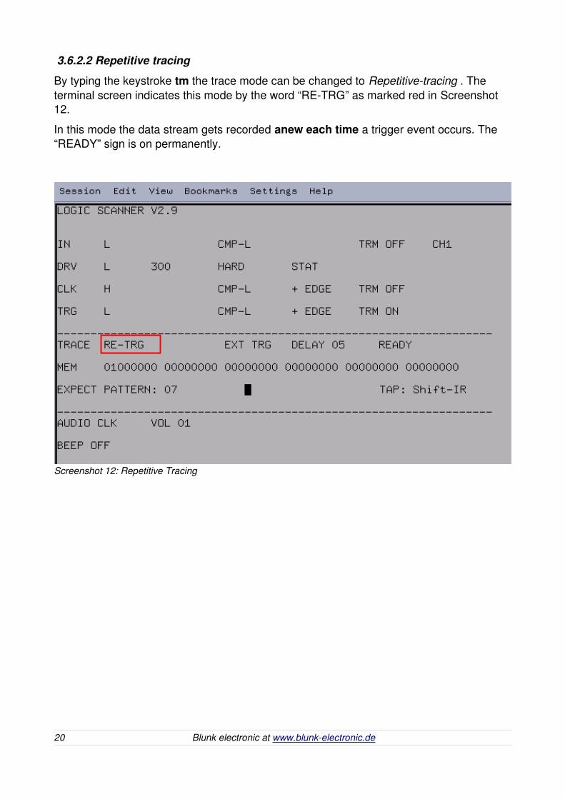
3.6.2.2 Repetitive tracing
By typing the keystroke tm the trace mode can be changed to Repetitivetracing . The terminal screen indicates this mode by the word “RETRG” as marked red in Screenshot 12.
In this mode the data stream gets recorded anew each time a trigger event occurs. The “READY” sign is on permanently.
20 Blunk electronic at www.blunkelectronic.de
Screenshot 12: Repetitive Tracing
3.7 Debugging Serial Buses
3.7.1 JTAG / IEEE 1149.x / Boundary Scan
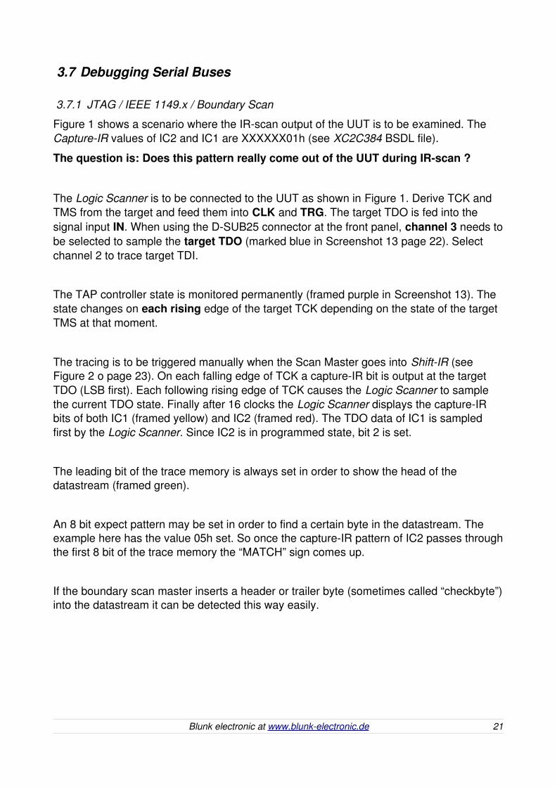
Figure 1 shows a scenario where the IRscan output of the UUT is to be examined. The CaptureIR values of IC2 and IC1 are XXXXXX01h (see XC2C384 BSDL file).
The question is: Does this pattern really come out of the UUT during IRscan ?
The Logic Scanner is to be connected to the UUT as shown in Figure 1. Derive TCK and TMS from the target and feed them into CLK and TRG. The target TDO is fed into the signal input IN. When using the DSUB25 connector at the front panel, channel 3 needs tobe selected to sample the target TDO (marked blue in Screenshot 13 page 22). Select channel 2 to trace target TDI.
The TAP controller state is monitored permanently (framed purple in Screenshot 13). The state changes on each rising edge of the target TCK depending on the state of the target TMS at that moment.
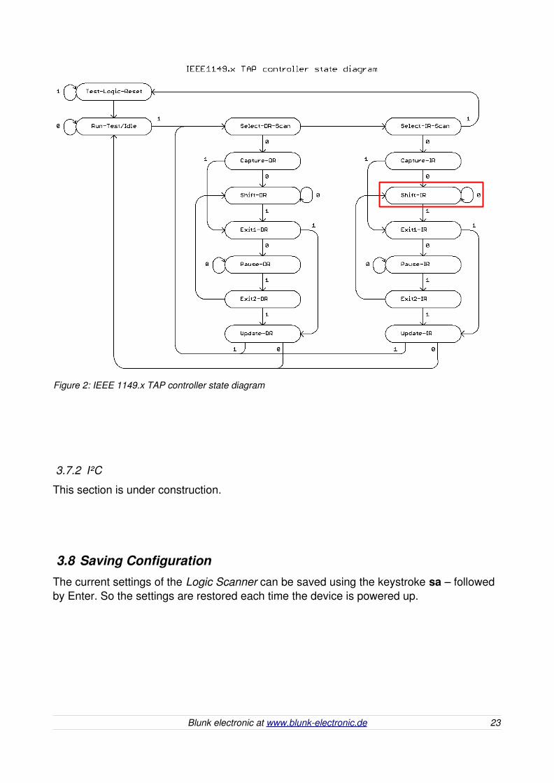
The tracing is to be triggered manually when the Scan Master goes into ShiftIR (seeFigure 2 o page 23). On each falling edge of TCK a captureIR bit is output at the target TDO (LSB first). Each following rising edge of TCK causes the Logic Scanner to sample the current TDO state. Finally after 16 clocks the Logic Scanner displays the captureIR bits of both IC1 (framed yellow) and IC2 (framed red). The TDO data of IC1 is sampled first by the Logic Scanner. Since IC2 is in programmed state, bit 2 is set.
The leading bit of the trace memory is always set in order to show the head of the datastream (framed green).
An 8 bit expect pattern may be set in order to find a certain byte in the datastream. The example here has the value 05h set. So once the captureIR pattern of IC2 passes throughthe first 8 bit of the trace memory the “MATCH” sign comes up.
If the boundary scan master inserts a header or trailer byte (sometimes called “checkbyte”)into the datastream it can be detected this way easily.
Blunk electronic at www.blunkelectronic.de 21

22 Blunk electronic at www.blunkelectronic.de
Screenshot 13: CaptureIR Tracing
Figure 1: Connecting with the Target TDO
3.7.2 I²C
This section is under construction.
3.8 Saving ConfigurationThe current settings of the Logic Scanner can be saved using the keystroke sa – followed by Enter. So the settings are restored each time the device is powered up.
Blunk electronic at www.blunkelectronic.de 23
Figure 2: IEEE 1149.x TAP controller state diagram

4 Keystrokes Reference Table
Input Signal Channel Select
c1 select input channel 1
c2 select input channel 2
c3 select input channel 3
Input Termination
ts 300 Ohms termination input signal on/off
tc 300 Ohms termination clock on/off
tt 300 Ohms termination trigger on/off
Signal Driver
ds0 signal driver strength: none � high-z
ds1 signal driver strength: 300 Ohms add probe internal resistance if regular oscilloscope probe used
ds2 signal driver strength: 1800 Ohms add probe internal resistance if regular oscilloscope probe used
ds3 signal driver strength: 10k Ohms add probe internal resistance if regular oscilloscope probe used
do signal driver output characteristic: pull-high/low/hard
dt signal driver: toggle/static
dv signal driver value: H/L if toggle mode active
fs filter input signal: schmitt-trigger/comp-L/H
fc filter clock: schmitt-trigger/comp-L/H
ft filter trigger: schmitt-trigger/comp-L/H
24 Blunk electronic at www.blunkelectronic.de
Pulse Detectors
ps input signal pulse detector: auto/man. acknowledge
pc clock pulse detector: auto/man. acknowledge
pt trigger pulse detector: auto/man. acknowledge
as acknowledge input signal pulse detection if signal pulse detector set to man. acknowledge
ac acknowledge clock pulse detection if clock pulse detector set to man. acknowledge
at acknowledge trigger pulse detection if trigger pulse detectorset to man. acknowledge
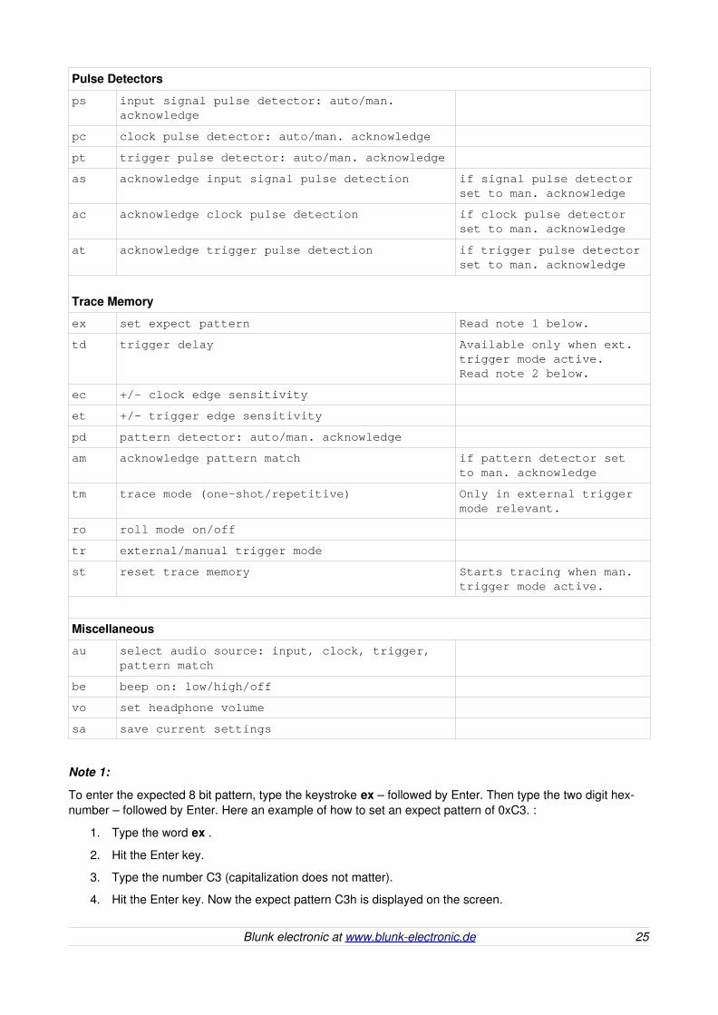
Trace Memory
ex set expect pattern Read note 1 below.
td trigger delay Available only when ext. trigger mode active.Read note 2 below.
ec +/- clock edge sensitivity
et +/- trigger edge sensitivity
pd pattern detector: auto/man. acknowledge
am acknowledge pattern match if pattern detector set to man. acknowledge
tm trace mode (one-shot/repetitive) Only in external trigger mode relevant.
ro roll mode on/off
tr external/manual trigger mode
st reset trace memory Starts tracing when man. trigger mode active.
Miscellaneous
au select audio source: input, clock, trigger, pattern match
be beep on: low/high/off
vo set headphone volume
sa save current settings
Note 1:
To enter the expected 8 bit pattern, type the keystroke ex – followed by Enter. Then type the two digit hexnumber – followed by Enter. Here an example of how to set an expect pattern of 0xC3. :
1. Type the word ex .
2. Hit the Enter key.
3. Type the number C3 (capitalization does not matter).
4. Hit the Enter key. Now the expect pattern C3h is displayed on the screen.
Blunk electronic at www.blunkelectronic.de 25

Note 2:
To enter an 4 bit trigger delay value, type the keystroke td – followed by Enter. Then type the two digit hexnumber – followed by Enter. The first digit must be a zero. Here an example of how to set a delay of 7 trigger edges:
1. Type the word td .
2. Hit the Enter key.
3. Type the number 07.
4. Hit the Enter key. Now the delay value of 07h is displayed on the screen.
26 Blunk electronic at www.blunkelectronic.de

5 RS232 and Terminal Program of the Host ComputerOn the host computer a terminal program is required. Users running Linux may use Minicom, under MSWindows the HyperTerminal program is recommended.
On Linux, if you are a nonroot user make sure you are member of the group uucp otherwise Minicom will not start and respond with the message: “Cannot create lockfile. Sorry.”.
Please make sure there is a serial interface in your computer at all. COM or ttyS ports are increasingly less to be found in laptop PCs. Thus connecting the Logic Scanner via a USBtoRS232Adapter is required. Please see section 5.1 on page 28 for more on this.
The parameters of the RS232 interface to communicate with the Logic Scanner are to be set somewhere within the terminal program:
data transfer rate 9600 bit/s
8 bits per character
no parity
1 stop bit
hardware flow control
Blunk electronic at www.blunkelectronic.de 27
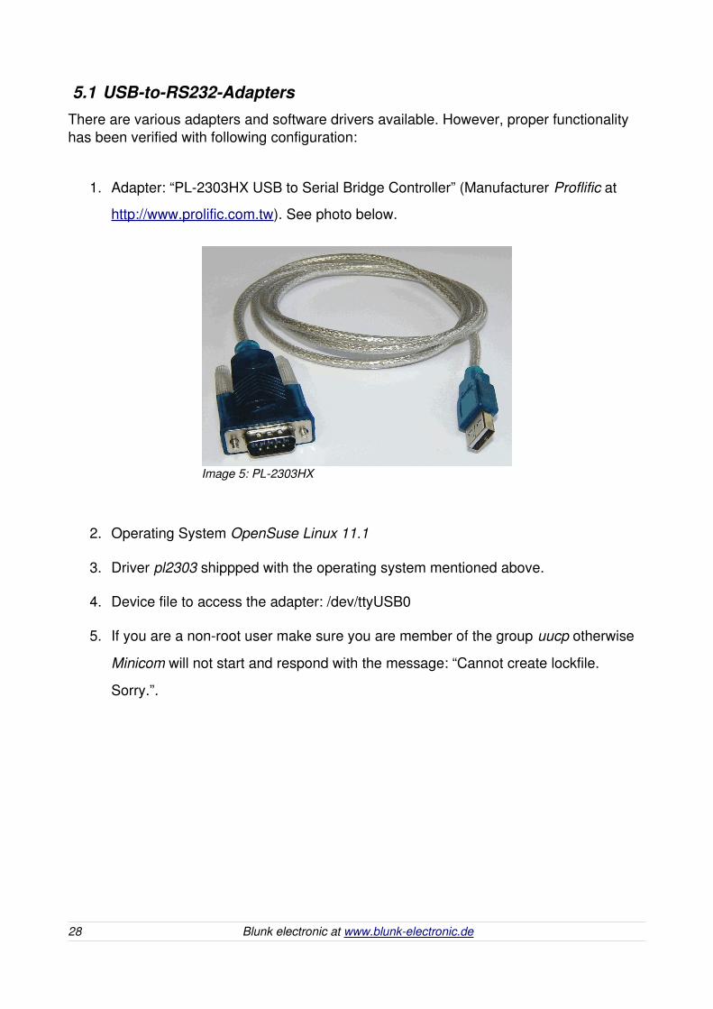
5.1 USBtoRS232AdaptersThere are various adapters and software drivers available. However, proper functionality has been verified with following configuration:
1. Adapter: “PL2303HX USB to Serial Bridge Controller” (Manufacturer Proflific at
http://www.prolific.com.tw). See photo below.
2. Operating System OpenSuse Linux 11.1
3. Driver pl2303 shippped with the operating system mentioned above.
4. Device file to access the adapter: /dev/ttyUSB0
5. If you are a nonroot user make sure you are member of the group uucp otherwise
Minicom will not start and respond with the message: “Cannot create lockfile.
Sorry.”.
28 Blunk electronic at www.blunkelectronic.de
Image 5: PL2303HX

When using Minicom under Linux the interface settings are shown below.
In the hardware management of MSWindows the adapter should appear as regular COM interface.
Blunk electronic at www.blunkelectronic.de 29
Screenshot 14: USB2Serial interface settings
6 Useful Links
Find updates of this document at www.blunkelectronic.de
Simplify manufacturing fault detection, hardware bringup, debugging and system tests with System M1 the BoundaryScan Test System at
http://www.blunkelectronic.de/products.html
7 DisclaimerThis document is believed to be accurate and reliable. I do not assume responsibility for inaccuracies any errors which may appear in this document. I reserve the right to change itat any time without notice, and do not make any commitment to update the information contained herein.
I am neither liable for direct damages nor consequential damages resulting from the application of this product.
Mario Blunk
Blunk electronic / Owner : Dipl.Ing. Mario Blunk / Buchfinkenweg 3 / 99097 Erfurt / Germany / Phone +49 361 6022 5184
© 2016 Mario Blunk Printed in Germany
30 Blunk electronic at www.blunkelectronic.de