logical sensors - greetings from eng....
TRANSCRIPT
1
Logical Sensors
A sensor element measures a process variable: flow rate, temperature, pressure, level, pH,
density, composition, etc. Much of the time, the measurement is inferred from a second variable:
flow and level are often computed from pressure measurements, composition from temperature
measurements. A transducer is a device that receives a signal and retransmits it in a different
form. For example, we've discussed I/P transducers that convert a current signal to pneumatic
form. Most industrial sensors act to detect process variables in the form of a position or voltage
change, and hence most sensors also function as transducers. For example, a thermocouple
represents a temperature change as a voltage change, while a displacer represents a level change
as a change in position of a rotating element. If the sensor element does not produce a signal
suitable for transmission through the plant, an additional transducer element is needed. This
combined sensor/transducer device is typically called a transmitter, at least in industrial settings.
Laboratory equipment manufacturers are likely to refer to the combined device as a transducer.
2
Logical Sensors
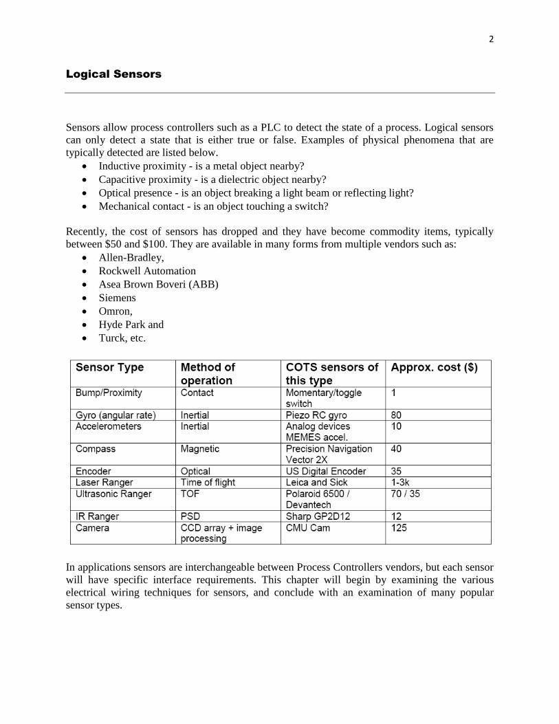
Sensors allow process controllers such as a PLC to detect the state of a process. Logical sensors
can only detect a state that is either true or false. Examples of physical phenomena that are
typically detected are listed below.
Inductive proximity - is a metal object nearby?
Capacitive proximity - is a dielectric object nearby?
Optical presence - is an object breaking a light beam or reflecting light?
Mechanical contact - is an object touching a switch?
Recently, the cost of sensors has dropped and they have become commodity items, typically
between $50 and $100. They are available in many forms from multiple vendors such as:
Allen-Bradley,
Rockwell Automation
Asea Brown Boveri (ABB)
Siemens
Omron,
Hyde Park and
Turck, etc.
In applications sensors are interchangeable between Process Controllers vendors, but each sensor
will have specific interface requirements. This chapter will begin by examining the various
electrical wiring techniques for sensors, and conclude with an examination of many popular
sensor types.
3
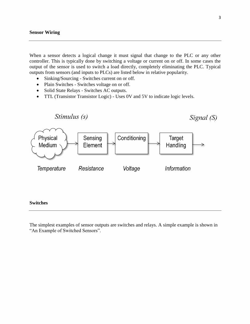
Sensor Wiring
When a sensor detects a logical change it must signal that change to the PLC or any other
controller. This is typically done by switching a voltage or current on or off. In some cases the
output of the sensor is used to switch a load directly, completely eliminating the PLC. Typical
outputs from sensors (and inputs to PLCs) are listed below in relative popularity.
Sinking/Sourcing - Switches current on or off.
Plain Switches - Switches voltage on or off.
Solid State Relays - Switches AC outputs.
TTL (Transistor Transistor Logic) - Uses 0V and 5V to indicate logic levels.
Switches
The simplest examples of sensor outputs are switches and relays. A simple example is shown in
“An Example of Switched Sensors”.
4
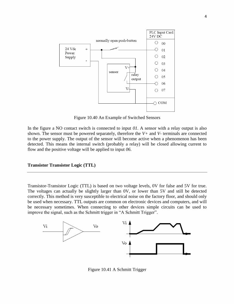
Figure 10.40 An Example of Switched Sensors
In the figure a NO contact switch is connected to input 01. A sensor with a relay output is also
shown. The sensor must be powered separately, therefore the V+ and V- terminals are connected
to the power supply. The output of the sensor will become active when a phenomenon has been
detected. This means the internal switch (probably a relay) will be closed allowing current to
flow and the positive voltage will be applied to input 06.
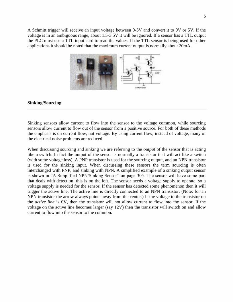
Transistor Transistor Logic (TTL)
Transistor-Transistor Logic (TTL) is based on two voltage levels, 0V for false and 5V for true.
The voltages can actually be slightly larger than 0V, or lower than 5V and still be detected
correctly. This method is very susceptible to electrical noise on the factory floor, and should only
be used when necessary. TTL outputs are common on electronic devices and computers, and will
be necessary sometimes. When connecting to other devices simple circuits can be used to
improve the signal, such as the Schmitt trigger in “A Schmitt Trigger”.
Figure 10.41 A Schmitt Trigger
5
A Schmitt trigger will receive an input voltage between 0-5V and convert it to 0V or 5V. If the
voltage is in an ambiguous range, about 1.5-3.5V it will be ignored. If a sensor has a TTL output
the PLC must use a TTL input card to read the values. If the TTL sensor is being used for other
applications it should be noted that the maximum current output is normally about 20mA.
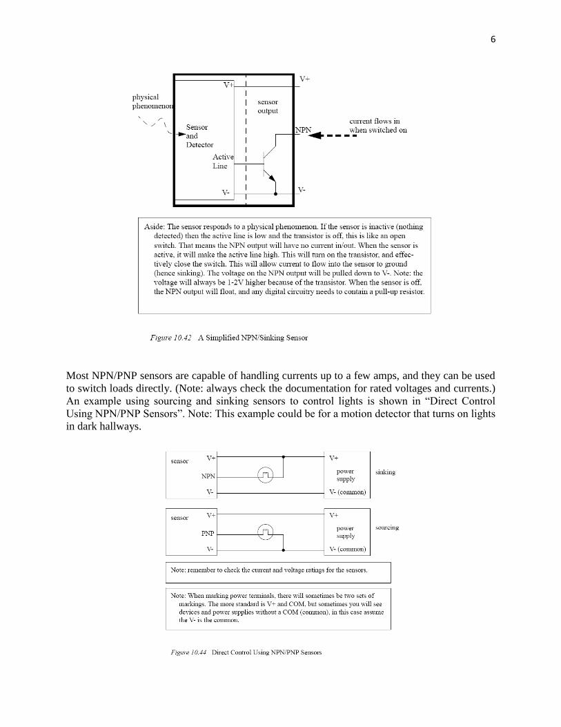
Sinking/Sourcing
Sinking sensors allow current to flow into the sensor to the voltage common, while sourcing
sensors allow current to flow out of the sensor from a positive source. For both of these methods
the emphasis is on current flow, not voltage. By using current flow, instead of voltage, many of
the electrical noise problems are reduced.
When discussing sourcing and sinking we are referring to the output of the sensor that is acting
like a switch. In fact the output of the sensor is normally a transistor that will act like a switch
(with some voltage loss). A PNP transistor is used for the sourcing output, and an NPN transistor
is used for the sinking input. When discussing these sensors the term sourcing is often
interchanged with PNP, and sinking with NPN. A simplified example of a sinking output sensor
is shown in “A Simplified NPN/Sinking Sensor” on page 305. The sensor will have some part
that deals with detection, this is on the left. The sensor needs a voltage supply to operate, so a
voltage supply is needed for the sensor. If the sensor has detected some phenomenon then it will
trigger the active line. The active line is directly connected to an NPN transistor. (Note: for an
NPN transistor the arrow always points away from the center.) If the voltage to the transistor on
the active line is 0V, then the transistor will not allow current to flow into the sensor. If the
voltage on the active line becomes larger (say 12V) then the transistor will switch on and allow
current to flow into the sensor to the common.
6
Most NPN/PNP sensors are capable of handling currents up to a few amps, and they can be used
to switch loads directly. (Note: always check the documentation for rated voltages and currents.)
An example using sourcing and sinking sensors to control lights is shown in “Direct Control
Using NPN/PNP Sensors”. Note: This example could be for a motion detector that turns on lights
in dark hallways.
7
In the sinking system in “Direct Control Using NPN/PNP Sensors” , the light has V+ applied to
one side. The other side is connected to the NPN output of the sensor. When the sensor turns on
the current will be able to flow through the light, into the output to V- common. (Note: Yes, the
current will be allowed to flow into the output for an NPN sensor.) In the sourcing arrangement
the light will turn on when the output becomes active, allowing current to flow from the V+,
thought the sensor, the light and to V- (the common).
Presence Detection
There are two basic ways to detect object presence; contact and proximity. Contact implies that
there is mechanical contact and a resulting force between the sensor and the object. Proximity
indicates that the object is near, but contact is not required. The following sections examine
different types of sensors for detecting object presence. These sensors account for a majority of
the sensors used in applications.
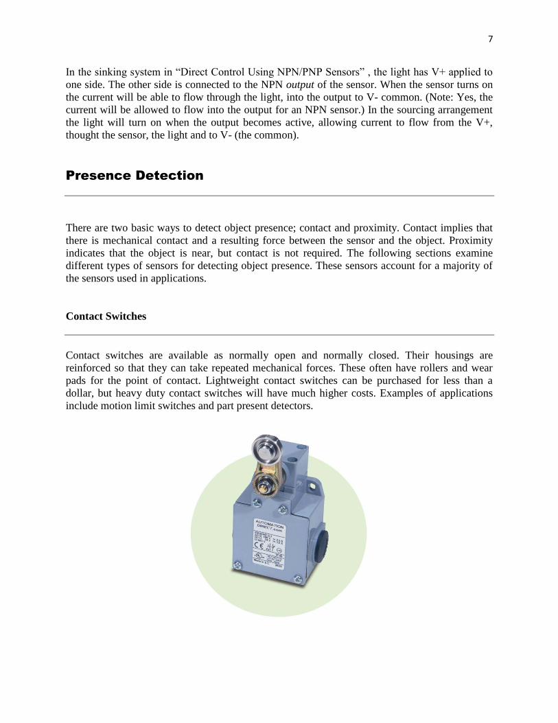
Contact Switches
Contact switches are available as normally open and normally closed. Their housings are
reinforced so that they can take repeated mechanical forces. These often have rollers and wear
pads for the point of contact. Lightweight contact switches can be purchased for less than a
dollar, but heavy duty contact switches will have much higher costs. Examples of applications
include motion limit switches and part present detectors.

8

9
10
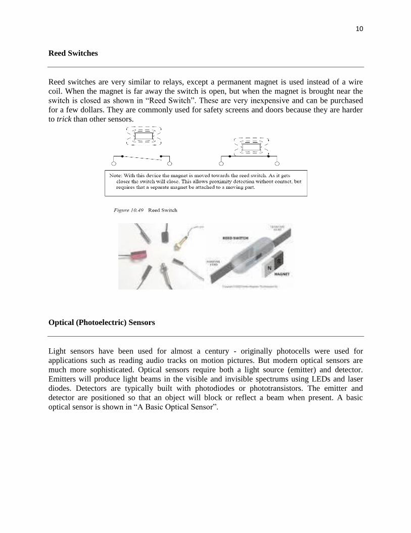
Reed Switches
Reed switches are very similar to relays, except a permanent magnet is used instead of a wire
coil. When the magnet is far away the switch is open, but when the magnet is brought near the
switch is closed as shown in “Reed Switch”. These are very inexpensive and can be purchased
for a few dollars. They are commonly used for safety screens and doors because they are harder
to trick than other sensors.
Optical (Photoelectric) Sensors
Light sensors have been used for almost a century - originally photocells were used for
applications such as reading audio tracks on motion pictures. But modern optical sensors are
much more sophisticated. Optical sensors require both a light source (emitter) and detector.
Emitters will produce light beams in the visible and invisible spectrums using LEDs and laser
diodes. Detectors are typically built with photodiodes or phototransistors. The emitter and
detector are positioned so that an object will block or reflect a beam when present. A basic
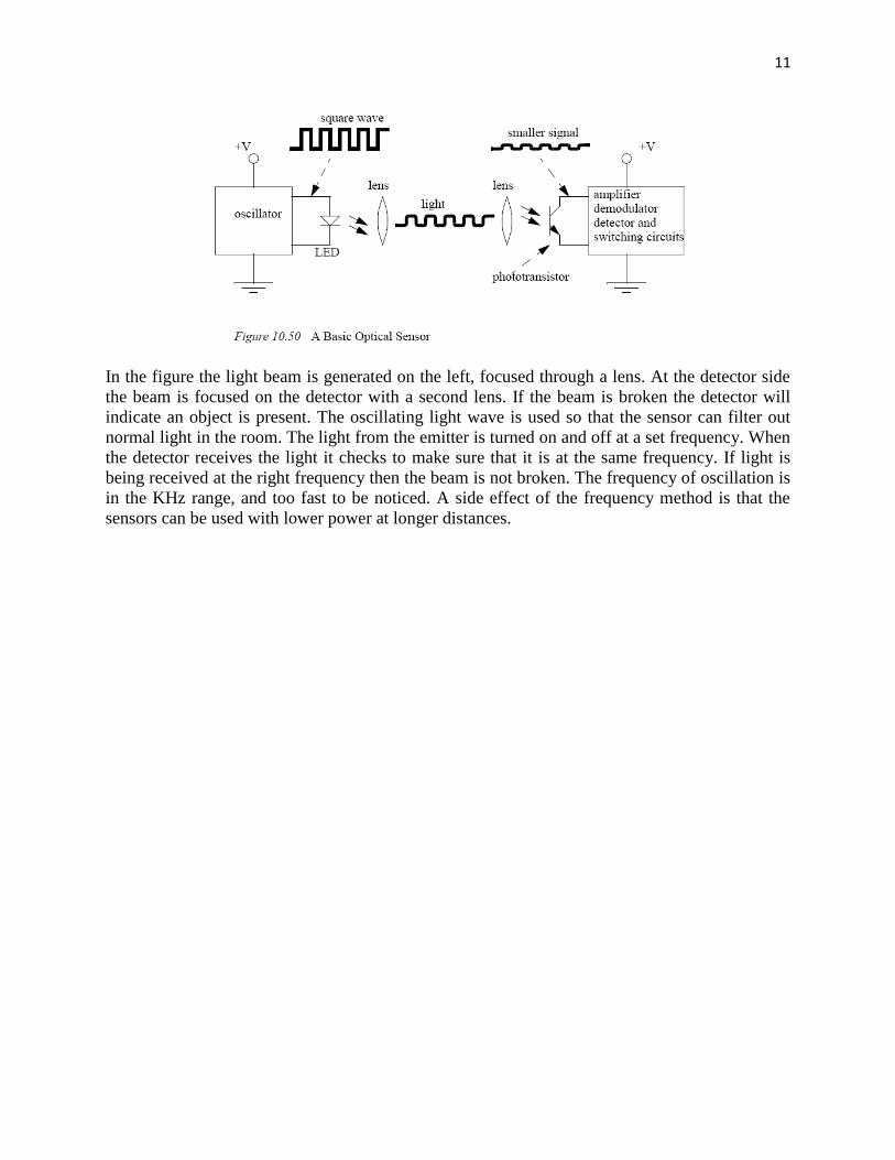
optical sensor is shown in “A Basic Optical Sensor”.
11
In the figure the light beam is generated on the left, focused through a lens. At the detector side
the beam is focused on the detector with a second lens. If the beam is broken the detector will
indicate an object is present. The oscillating light wave is used so that the sensor can filter out
normal light in the room. The light from the emitter is turned on and off at a set frequency. When
the detector receives the light it checks to make sure that it is at the same frequency. If light is
being received at the right frequency then the beam is not broken. The frequency of oscillation is
in the KHz range, and too fast to be noticed. A side effect of the frequency method is that the
sensors can be used with lower power at longer distances.
12

13
14
Capacitive Sensors
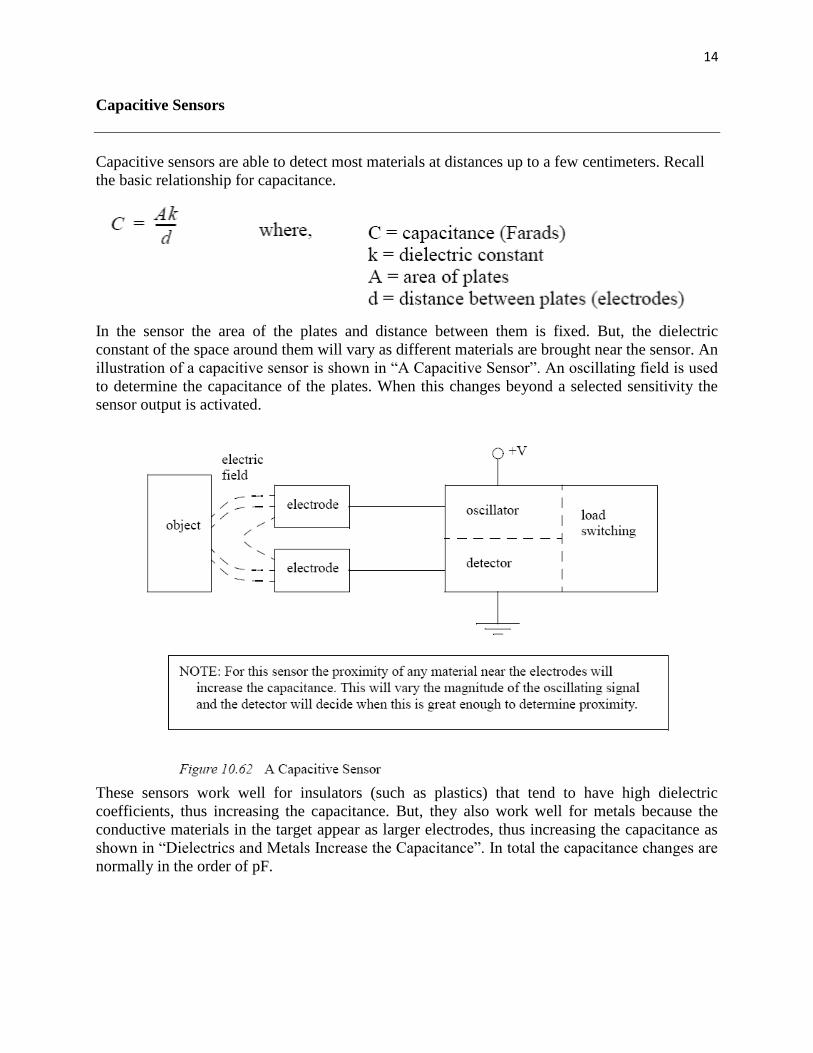
Capacitive sensors are able to detect most materials at distances up to a few centimeters. Recall
the basic relationship for capacitance.
In the sensor the area of the plates and distance between them is fixed. But, the dielectric
constant of the space around them will vary as different materials are brought near the sensor. An
illustration of a capacitive sensor is shown in “A Capacitive Sensor”. An oscillating field is used
to determine the capacitance of the plates. When this changes beyond a selected sensitivity the
sensor output is activated.
These sensors work well for insulators (such as plastics) that tend to have high dielectric
coefficients, thus increasing the capacitance. But, they also work well for metals because the
conductive materials in the target appear as larger electrodes, thus increasing the capacitance as
shown in “Dielectrics and Metals Increase the Capacitance”. In total the capacitance changes are
normally in the order of pF.
15
Inductive Sensors
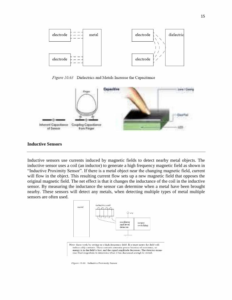
Inductive sensors use currents induced by magnetic fields to detect nearby metal objects. The
inductive sensor uses a coil (an inductor) to generate a high frequency magnetic field as shown in
“Inductive Proximity Sensor”. If there is a metal object near the changing magnetic field, current
will flow in the object. This resulting current flow sets up a new magnetic field that opposes the
original magnetic field. The net effect is that it changes the inductance of the coil in the inductive
sensor. By measuring the inductance the sensor can determine when a metal have been brought
nearby. These sensors will detect any metals, when detecting multiple types of metal multiple
sensors are often used.
16
17
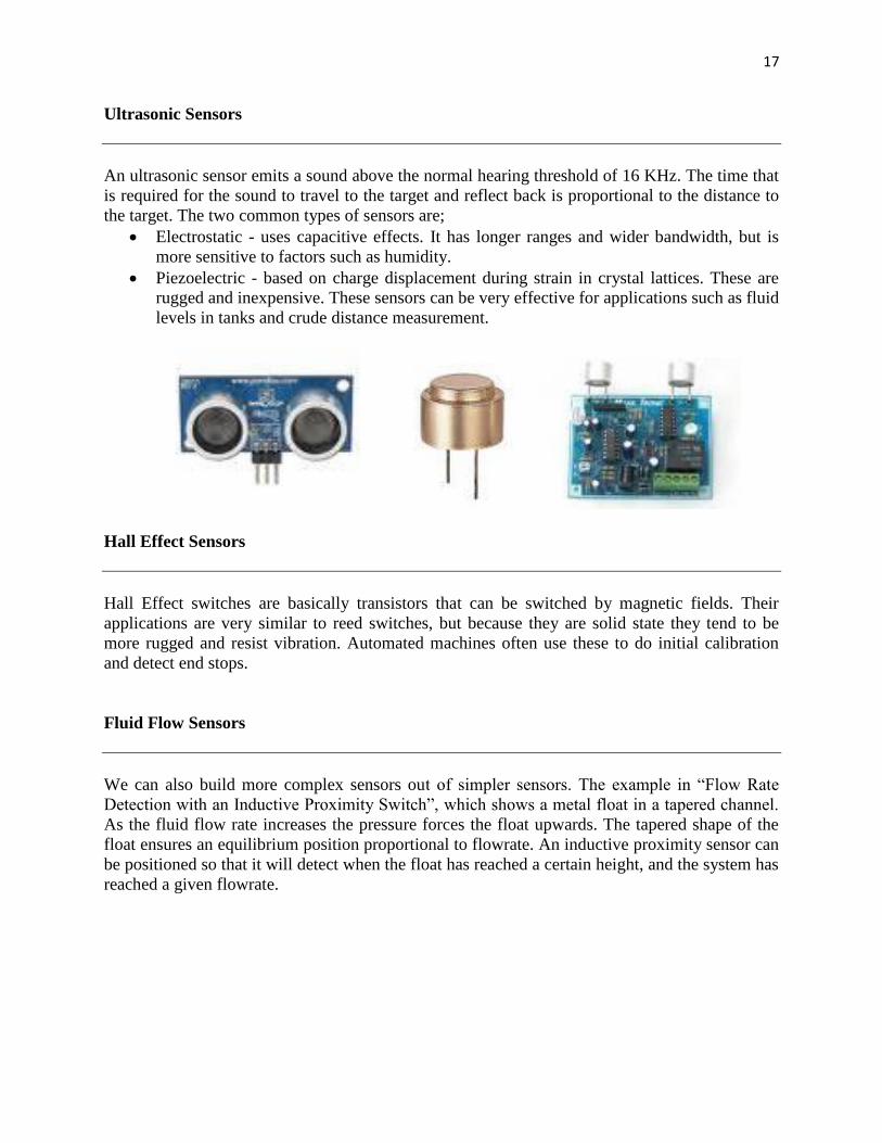
Ultrasonic Sensors
An ultrasonic sensor emits a sound above the normal hearing threshold of 16 KHz. The time that
is required for the sound to travel to the target and reflect back is proportional to the distance to
the target. The two common types of sensors are;
Electrostatic - uses capacitive effects. It has longer ranges and wider bandwidth, but is
more sensitive to factors such as humidity.
Piezoelectric - based on charge displacement during strain in crystal lattices. These are
rugged and inexpensive. These sensors can be very effective for applications such as fluid
levels in tanks and crude distance measurement.
Hall Effect Sensors
Hall Effect switches are basically transistors that can be switched by magnetic fields. Their
applications are very similar to reed switches, but because they are solid state they tend to be
more rugged and resist vibration. Automated machines often use these to do initial calibration
and detect end stops.
Fluid Flow Sensors
We can also build more complex sensors out of simpler sensors. The example in “Flow Rate
Detection with an Inductive Proximity Switch”, which shows a metal float in a tapered channel.
As the fluid flow rate increases the pressure forces the float upwards. The tapered shape of the
float ensures an equilibrium position proportional to flowrate. An inductive proximity sensor can
be positioned so that it will detect when the float has reached a certain height, and the system has
reached a given flowrate.
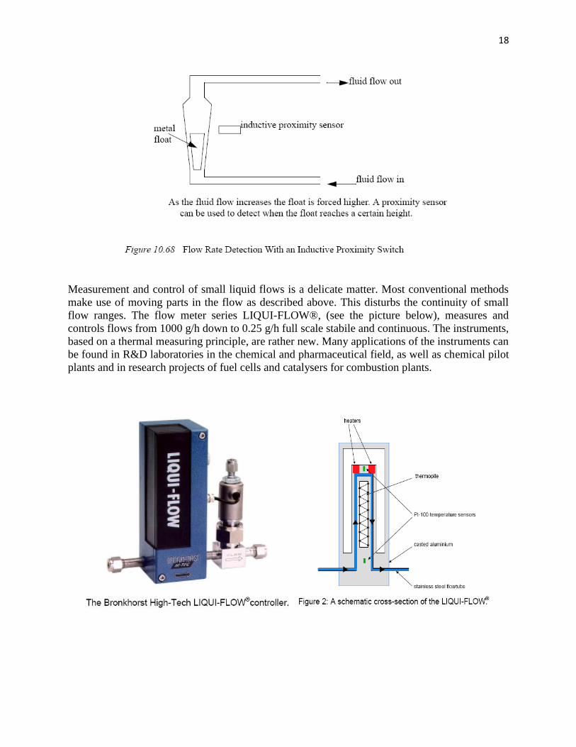
18
Measurement and control of small liquid flows is a delicate matter. Most conventional methods
make use of moving parts in the flow as described above. This disturbs the continuity of small
flow ranges. The flow meter series LIQUI-FLOW®, (see the picture below), measures and
controls flows from 1000 g/h down to 0.25 g/h full scale stabile and continuous. The instruments,
based on a thermal measuring principle, are rather new. Many applications of the instruments can
be found in R&D laboratories in the chemical and pharmaceutical field, as well as chemical pilot
plants and in research projects of fuel cells and catalysers for combustion plants.
19
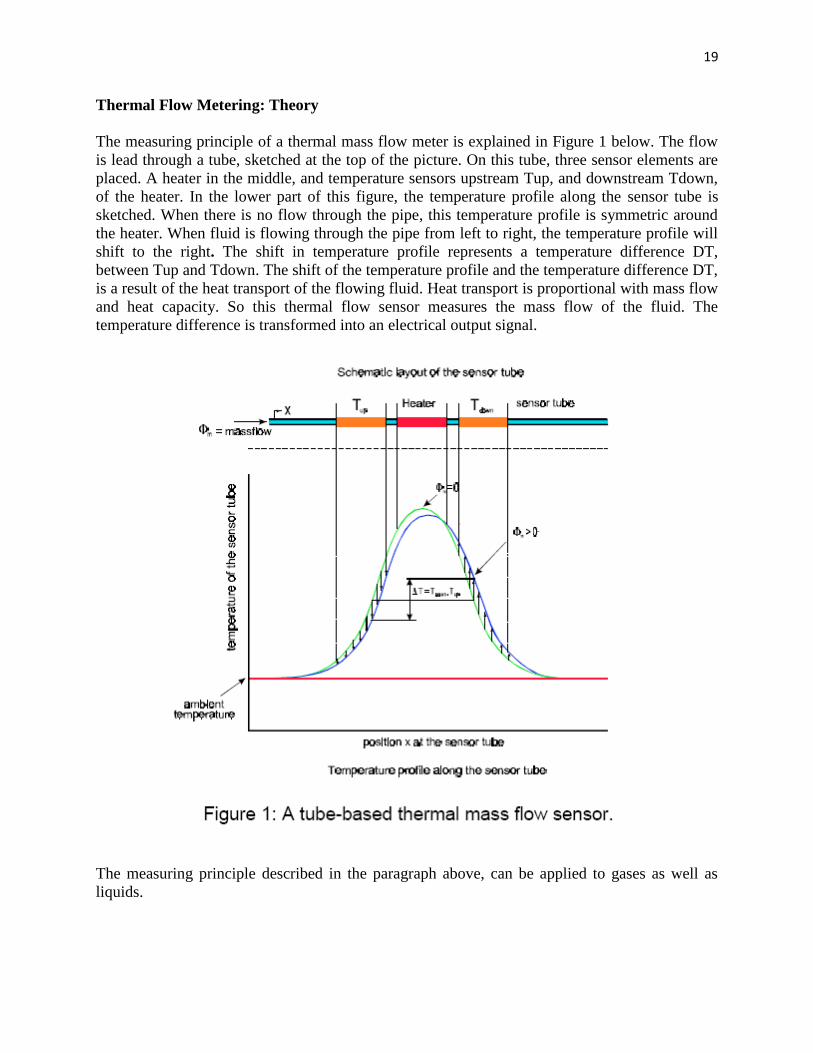
Thermal Flow Metering: Theory
The measuring principle of a thermal mass flow meter is explained in Figure 1 below. The flow
is lead through a tube, sketched at the top of the picture. On this tube, three sensor elements are
placed. A heater in the middle, and temperature sensors upstream Tup, and downstream Tdown,
of the heater. In the lower part of this figure, the temperature profile along the sensor tube is
sketched. When there is no flow through the pipe, this temperature profile is symmetric around
the heater. When fluid is flowing through the pipe from left to right, the temperature profile will
shift to the right. The shift in temperature profile represents a temperature difference DT,
between Tup and Tdown. The shift of the temperature profile and the temperature difference DT,
is a result of the heat transport of the flowing fluid. Heat transport is proportional with mass flow
and heat capacity. So this thermal flow sensor measures the mass flow of the fluid. The
temperature difference is transformed into an electrical output signal.
The measuring principle described in the paragraph above, can be applied to gases as well as
liquids.
20
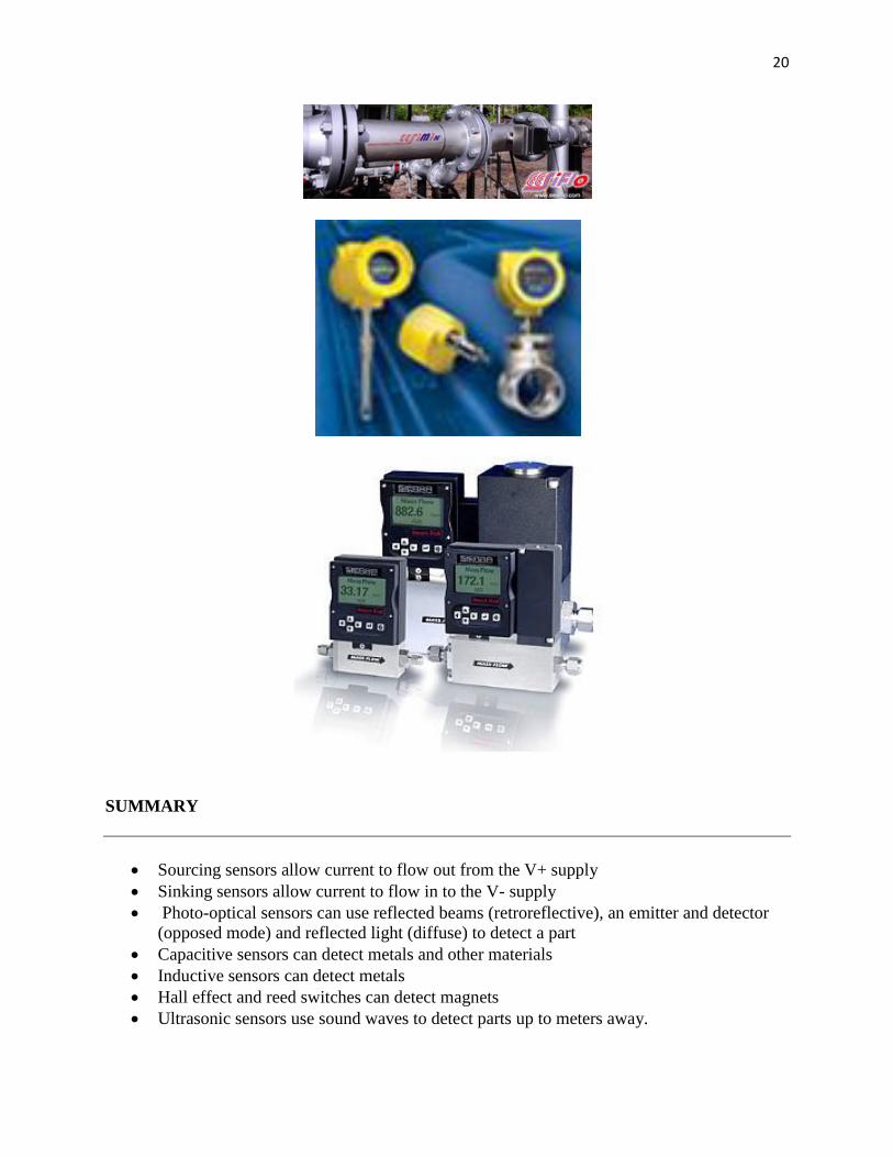
SUMMARY
Sourcing sensors allow current to flow out from the V+ supply
Sinking sensors allow current to flow in to the V- supply
Photo-optical sensors can use reflected beams (retroreflective), an emitter and detector
(opposed mode) and reflected light (diffuse) to detect a part
Capacitive sensors can detect metals and other materials
Inductive sensors can detect metals
Hall effect and reed switches can detect magnets Ultrasonic sensors use sound waves to detect parts up to meters away.

21