logikmodul lm/s 1 - abb group · the logic module makes 12 different functions available in one...
TRANSCRIPT

ABB i-bus® EIB
LM/S 1.1LM/S 1.1
9 9
Logic module, MDRCLM/S 1.1, GH Q631 0080 R0111
Page 1 of 31LMS_11_TD_DE_V1-1
2CDC 509 025 D0201
The logic module is a DIN railmounted device for insertion in thedistribution board. The connection tothe EIB is carried out via a busconnecting terminal.
The logic module is used in morecomplex EIB installations in order tocreate special logic operationsbetween sensors and actuators.
At least 3 logic or time functions canalways be set in each logic moduleboth simultaneously andindependently of each other.
Technical data
Power supply – EIB 24 VDC, via the bus lineOperating and display elements – LED (red) and push button for assigning the
physical addressType of protection – IP 20, EN 60 529Protection class – IIAmbient temperature range – Operation - 5 °C … 45 °CConnection – EIB Bus connecting terminal
included with supplyInstallation – on 35 mm mounting rail, DIN EN 60 715Dimensions – 90 x 36 x 64 mm (H x W x D)Weight – 0.1 kgCertification – EIB-certifiedCE norm – in accordance with the EMC guideline
and the low voltage guideline
The following functions can beimplemented with the logic module:– Logic gates– Gate/filter– Time delay– Multiplier– Min./Max. value indication– Temperature comparator– Toggle value– Threshold value– Format converter– Scenes– Counter– Staircase light
2CD
C 0
71 4
07 F
0003

ABB i-bus® EIB
LM/S 1.1LM/S 1.1
9 9
Logic module, MDRCLM/S 1.1, GH Q631 0080 R0111
Page 2 of 31LMS_11_TD_DE_V1-1
2CDC 509 025 D0201
Circuit diagram
1 Bus connection 3 Label2 Programming LED, button
Application programs Number of Max. number of Max. number ofcommunication objects group addresses associations
Logic Threshold Scene /1 48 250 250
Application programs
Note To commission the logic module, youneed a PC with the Engineering ToolSoftware ETS (from ETS2 V1.2aonwards) and an interface to the EIB(e.g. via an RS232 interface).
2CD
C 0
72 3
26 F
0003

ABB i-bus® EIB
LM/S 1.1LM/S 1.1
9 9
Logic module, MDRCLM/S 1.1, GH Q631 0080 R0111
Page 3 of 31LMS_11_TD_DE_V1-1
2CDC 509 025 D0201
Logic Threshold Scene /1
Selection in ETS2
– ABBController
Controller
Each EIB installation has its ownrequirements. The logic modulemakes 12 different functions availablein one device for special logicoperations between sensors andactuators:– Logic gates– Gate/filter– Time delay– Multiplier– Min./Max. value indication– Temperature comparator– Toggle value– Threshold value– Format converter– Scenes– Counter– Staircase light
Each logic module can always carryout three of the functions listed abovesimultaneously. The functionality of thethree functions A, B and C is definedon the “General” parameter page.
The functionality of function A forexample is defined via the setting“Function A”. Different parameters andcommunication objects are displayeddepending on the setting.
It is possible to assign the differentfunctions with any or the samefunctionality. The logic module cantherefore be adapted to a wide varietyof applications.
The individual functions are describedin the following section. All thedescriptions refer to function A as wellas functions B and C.
�
�
����
Format converter
The following bit sizes can bechanged with the “Format converter”function:– 2x1-Bit --> 1x2-Bit– 8x1-Bit --> 1-Byte– 1x1-Byte --> 2-Byte– 2x1-Byte --> 2-Byte– 2x2-Byte --> 4-Byte– 1x2-Bit --> 2x1-Bit– 1-Byte --> 8x1-Bit– 2-Byte --> 2x1-Byte– 4-Byte --> 2x2-Byte
With the parameter “Converterfunction”, it is defined which datatypes should be transferred. The ETSprogram displays differentcommunication objects depending onthe setting.
In general, the first bit/byte (0) alwayshas the lowest value while the last bit/byte (e.g. 7) always has the highestvalue. The conversion should beexplained in more detail using thefollowing example.
Note:Telegrams are broken down orcompiled on the format level. It istherefore not possible to assign aspecific EIS type to the input andoutput objects.
An association between the objectand an EIS type first originates fromthe context of the ETS project, inwhich this function is used.
Example: 2x1-Bit --> 1x2-BitInput:
21 20
Bit1 Bit01 1
Output:2 bit value: 3dec
Example: 1-Byte --> 8x1-BitInput:1 byte value: 169dec
Output:27 26 25 24 23 22 21 20
Bit7 Bit6 Bit5 Bit4 Bit3 Bit2 Bit1 Bit01 0 1 0 1 0 0 1
The conversion of 8x 1 bit into 1 byte iscarried out in the same way.

ABB i-bus® EIB
LM/S 1.1LM/S 1.1
9 9
Logic module, MDRCLM/S 1.1, GH Q631 0080 R0111
Page 4 of 31LMS_11_TD_DE_V1-1
2CDC 509 025 D0201
The conversion of 1x1 byte into 1x2byte represents a special case. Theinput byte in (EIS6) format istransferred into a 2 byte value (EIS10).It is possible for example with thisconversion to combine the 1 byteoutput of the EIB current module withthe 2 byte input value of the analogueactuator.
When converting from 2x1 byte into a2 byte value or from a 2 byte valueinto 2x1 byte values, the 1 byte valuesform a low byte and a high byte. Thelow byte is the lowest value byte andcreates bit numbers 0 to 7 (20 to 27)while the high byte creates bitnumbers 8 to 15 (28 to 215).
The above diagram shows anapplication example for the formatconverter. The 1 byte controller statuswhich is sent by a room thermostatshould be indicated on an LC display.First of all, the parameter “Converterfunction” of function A is set to “1-Byte--> 8x1-Bit”. The 1 byte communicationobject of the room thermostat is thenlinked to the 1 byte input object of theformat converter. The eight 1 bitoutputs are linked to the eight 1 bitinputs of the LC display.
Bus voltage recovery
Since not all telegrams are generallysent immediately to the inputs after abus voltage recovery, it is possible inthis case to read out the input value orinput values via the bus in order to putthe input in a defined state.
If the parameter “Read input valuesover EIB after bus voltage recovery” isset to “Yes” for this purpose, the logicmodule waits 5 seconds after startingup and then sends correspondingread telegrams to the linked groupaddresses.
Send output values
Under “Send output values”, it can beselected when an output telegramshould be sent. If it is set to “on objectvalue change”, an output telegram isonly sent when the value of the objecthas changed e.g. from “0” to “1”. If theoutput should also be sent each timea telegram is received at one of theinputs, the option “on reception of newtelegram” must be set. In this case, anoutput telegram is also sent if thevalue of the output has not beenchanged.
Example of a format converter1 byte --> 8x1 bit
The 1 byte status value is issued bythe room thermostat and convertedinto 8x1 bit variables in the logicmodule. They can be shown on the LCdisplay.

ABB i-bus® EIB
LM/S 1.1LM/S 1.1
9 9
Logic module, MDRCLM/S 1.1, GH Q631 0080 R0111
Page 5 of 31LMS_11_TD_DE_V1-1
2CDC 509 025 D0201
A
BQ
A
BQ
A
BQ
A
BQ
A
BQ
A
BQ
AND OR
NAND (NOT-AND) NOR (NOT-OR)
XOR (Exclusive-OR) XNOR (Equivalence)
& >1_
& >1_
=1 =
A B Q0 0
00 11 1
1
1000
A B Q0 0
00 11 1
1
A B Q0 0
00 11 1
1
A B Q0 0
00 11 1
1
A B Q0 0
00 11 1
1
A B Q0 0
00 11 1
1
111
0
1110
000
1
0
0
11
1
1
00
1 2
Logic gates
If the “Logic” function is selected in the“General” window, the ETSparameters and communicationobjects indicate which logic functionscan be implemented. These logicfunctionalities are required e.g. to setup more complex logic operationswhich can no longer be implementedwith the standard logic operations ofswitch or shutter actuators.
The diagram above shows all thepossible logic operations with theassociated truth tables. Via theparameter “Logical operation”, it ispossible to choose between thefollowing functions:– AND– OR– Exclusive OR– NAND– NOR– Equivalence
Inputs
A maximum of 8 inputs can beisolated for each function. This iscarried out via the setting “Input ...”.Inputs 1 to 4 are shown as “normal” bydefault. Alternatively, the inputs canalso be switched to “inverted” or“inactive” (“not used”). Inputs 5 to 8are inactive by default (“not used”).Inputs 5 to 8 can likewise be isolated(“normal”) or inverted via the setting“Input ...”.
ETS displays a unique 1 bitcommunication object for each activeinput. A group address is linked to thisobject. After each receipt of a telegramat one of a maximum of 8 inputs, theoutput signal is regenerated.
Output
The output of the logic operation lieson the 1 bit communication object “...:Logic output - Send telegram”. Thissignal can be inverted via the setting“Output”. It is defined with theparameter “Send output values” whenthe output should send out a telegram.This can be “on reception of newtelegram” (the output is sent afterreceipt of an input telegram,regardless of whether the outputvalue has changed or not) or only “onobject value change” (after receipt ofan input telegram that calls up achange in the output signal).
It is possible to also set a send delayin the two settings above for the sendbehaviour of the output. This meansthat the output signal is only sent oncethis delay has elapsed. The delay iscomposed of a base and a factor.
Send delay = Base * Factor
If the output value should changeagain within the send delay, the “old”output value is no longer sent. Thelogic module adopts the new outputvalue and restarts the send delay.
Logic gates with truth tablesThe logic gates listed on the right canbe set. The gates and the tablesdescribe the input and output statesfor only 2 inputs. If there are severalinputs, the tables must be extendedaccordingly.
1 If there is an uneven number ofinputs which are set to ON (receiveON telegram), the output is alsoalways ON (sends an ON telegram).
2 If there is an uneven number ofinputs which are set to OFF (receiveOFF telegram), the output is alsoalways ON (sends an ON telegram).

ABB i-bus® EIB
LM/S 1.1LM/S 1.1
9 9
Logic module, MDRCLM/S 1.1, GH Q631 0080 R0111
Page 6 of 31LMS_11_TD_DE_V1-1
2CDC 509 025 D0201
Alternatively, the output value can besent cyclically. To do so, the parameter“Send output values” must be set to“cyclic”. The cyclic interval with whichthe output value is sent is composedof a base value and a factor.
Cyclic interval = Base * Factor
Bus voltage recovery
Since not all telegrams are generallysent immediately to the inputs after abus voltage recovery, it is possible inthis case to use either “use valuebefore bus voltage fail” or “readvalues over EIB” in order to put theinput in a defined state. It is alsopossible to select “use 0 as preset” or“use 1 as preset” to define the input.
Min./Max. value indication
If the functionality “Min./Max. valueindication” is selected, the ETSprogram displays 4 inputcommunication objects and 1 outputcommunication object. The parameter“Data type of the inputs” defines thesize of the communication objects.They can be the following types:– 1-Byte Value in % EIS6– 1-Byte Orientation in degrees EIS6– 1-Byte Counter (0…255) EIS14– 1-Byte Counter (-128…+127) EIS14– 2-Byte Counter (0…65.535) EIS10– 2-Byte Floating point value EIS5– 2-Byte Counter (-32.768…+32.767)
EIS10– 4-Byte Floating point value EIS9– 4-Byte Counter
(-10.000.000…+10.000.000) EIS11
Each of the 4 inputs can be enabled(“used”) or disabled (“not used”) via aseparate parameter “Input ...”.
Depending on the setting of the“Output” parameter, the output eitheradopts the highest value, the lowestvalue or the average.
With the parameter “Send outputvalues”, it is defined when the outputshould send a telegram. This can be“on reception of new telegram” (theoutput is sent after receipt of an inputtelegram, regardless of whether theoutput value has changed or not) oronly “on object value change” (afterreceipt of an input telegram that callsup a change in the output signal).
Alternatively, the output value can besent cyclically. To do so, the parameter“Send output values” must be set to“cyclic”. The cyclic interval with whichthe output value is sent is composedof a base value and a factor.
Cyclic interval = Base * Factor
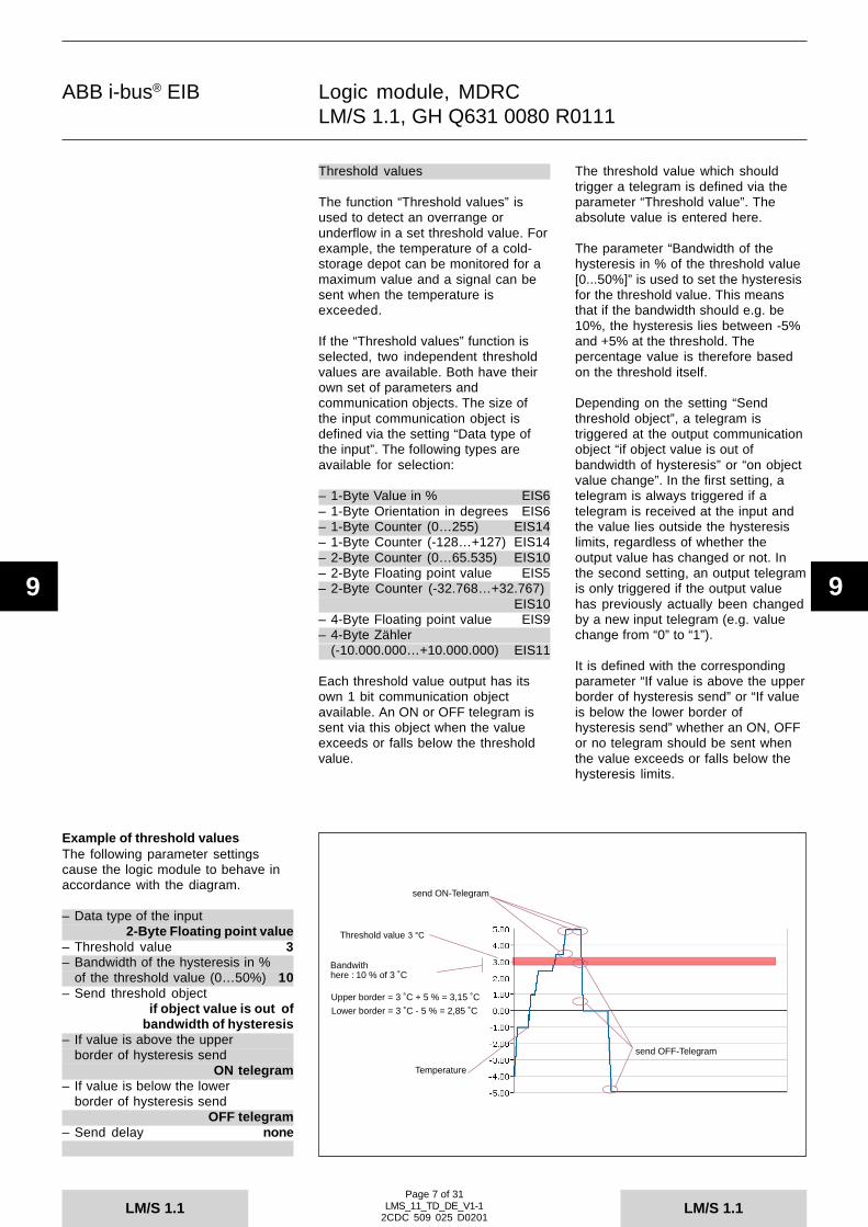
ABB i-bus® EIB
LM/S 1.1LM/S 1.1
9 9
Logic module, MDRCLM/S 1.1, GH Q631 0080 R0111
Page 7 of 31LMS_11_TD_DE_V1-1
2CDC 509 025 D0201
Threshold value
send ON-Telegram
Bandwithhere : 10 % of 3 ˚C
Upper border = 3 ˚C + 5 % = 3,15 ˚C
Lower border = 3 ˚C - 5 % = 2,85 ˚C
send OFF-Telegram
Temperature
Threshold values
The function “Threshold values” isused to detect an overrange orunderflow in a set threshold value. Forexample, the temperature of a cold-storage depot can be monitored for amaximum value and a signal can besent when the temperature isexceeded.
If the “Threshold values” function isselected, two independent thresholdvalues are available. Both have theirown set of parameters andcommunication objects. The size ofthe input communication object isdefined via the setting “Data type ofthe input”. The following types areavailable for selection:
– 1-Byte Value in % EIS6– 1-Byte Orientation in degrees EIS6– 1-Byte Counter (0…255) EIS14– 1-Byte Counter (-128…+127) EIS14– 2-Byte Counter (0…65.535) EIS10– 2-Byte Floating point value EIS5– 2-Byte Counter (-32.768…+32.767)
EIS10– 4-Byte Floating point value EIS9– 4-Byte Zähler
(-10.000.000…+10.000.000) EIS11
Each threshold value output has itsown 1 bit communication objectavailable. An ON or OFF telegram issent via this object when the valueexceeds or falls below the thresholdvalue.
The threshold value which shouldtrigger a telegram is defined via theparameter “Threshold value”. Theabsolute value is entered here.
The parameter “Bandwidth of thehysteresis in % of the threshold value[0...50%]” is used to set the hysteresisfor the threshold value. This meansthat if the bandwidth should e.g. be10%, the hysteresis lies between -5%and +5% at the threshold. Thepercentage value is therefore basedon the threshold itself.
Depending on the setting “Sendthreshold object”, a telegram istriggered at the output communicationobject “if object value is out ofbandwidth of hysteresis” or “on objectvalue change”. In the first setting, atelegram is always triggered if atelegram is received at the input andthe value lies outside the hysteresislimits, regardless of whether theoutput value has changed or not. Inthe second setting, an output telegramis only triggered if the output valuehas previously actually been changedby a new input telegram (e.g. valuechange from “0” to “1”).
It is defined with the correspondingparameter “If value is above the upperborder of hysteresis send” or “If valueis below the lower border ofhysteresis send” whether an ON, OFFor no telegram should be sent whenthe value exceeds or falls below thehysteresis limits.
Example of threshold valuesThe following parameter settingscause the logic module to behave inaccordance with the diagram.
– Data type of the input2-Byte Floating point value
– Threshold value 3– Bandwidth of the hysteresis in %
of the threshold value (0…50%) 10– Send threshold object
if object value is out ofbandwidth of hysteresis
– If value is above the upperborder of hysteresis send
ON telegram– If value is below the lower
border of hysteresis sendOFF telegram
– Send delay none

ABB i-bus® EIB
LM/S 1.1LM/S 1.1
9 9
Logic module, MDRCLM/S 1.1, GH Q631 0080 R0111
Page 8 of 31LMS_11_TD_DE_V1-1
2CDC 509 025 D0201
It is also possible to set a send delayfor the send behaviour of the output.This means that the output signal isonly sent once this delay has elapsed.The delay is composed of a base anda factor.
Send delay = Base * Factor
If the output value should changeagain within the send delay, the “old”output value is no longer sent. Thelogic module adopts the new outputvalue and restarts the send delay.
Scenes
With the “Scenes” function, the logicmodule is used as a scene module. Amaximum of 8 scenes can be storedand retrieved in one function. Thenumber of scenes that can bedisplayed and retrieved is dependenton the setting in the 4 parameters“Use scenes ...”. 2 scenes can beenabled via each of the 4 parameters.
The ETS program displays a common1 bit communication object “Scenecall ...” for every 2 scenes. For scenes1 and 2 this means e.g. a telegramwith the value “0” recalls scene 1while scene 2 is recalled by atelegram with the value “1”. Any EIBswitch sensor or universal interfacecan thus recall the stored scenes withthe “Switch” application.
There are 6 output communicationobjects available for each scene forcontrolling the actuators. It is possibleto control actuators with 1 bit inputobjects (switch or shutter actuators),actuators with 1 byte input objects(dimming actuators or 1 bytepositioning for shutter actuators) orroom thermostats with 2 byte inputobjects. The size of the outputcommunication objects is definedseparately for each output via thesetting “Data type of output ...“.
Data types:1-Bit Value EIS11-Byte Value in % (0…100%) EIS61-Byte Value (0…255) EIS62-Byte Temperature value EIS5
So that the end user has the option ofmodifying the prestored sceneshimself, there is a 1 bit communicationobject “Scene programming mode”. Ifan ON telegram is received at thiscommunication object, all the outputobjects trigger read requests insequence with the “sending” groupaddress. The values of the receivedresponse telegrams are stored in theEEPROM, so that they are not lostafter bus voltage failure.
Note:To be able to respond to readrequests, the read flag must be set forthe linked communication objects ofthe actuators.
The end user is therefore able to set,store and retrieve his own favouritescenes himself. The following processmust be noted:– Set all the actuators or room
thermostats involved to the requiredposition or preselect the requiredvalue (via separate push buttonsand group addresses)
– then activate the storing of thescene e.g. via a 1-fold switch sensor
– retrieve the scene that should bemodified
– switch off the storing of the scene– after a save which takes a certain
period, he can recall the storedvalues at any time.
Important:Unused actuator groups must havethe parameter setting “no reaction”.Otherwise, it is not possible to storescenes.
The information that a scene has beenstored is sent via the 1 bitcommunication object “Scene Saveindication” after a save.
The communication object “SceneReset to preset” is used to enable theoriginal settings (parameter settings)of the outputs to be retrieved at anytime.
The preset options of the outputs aredefined separately for each output viaits own parameters.

ABB i-bus® EIB
LM/S 1.1LM/S 1.1
9 9
Logic module, MDRCLM/S 1.1, GH Q631 0080 R0111
Page 9 of 31LMS_11_TD_DE_V1-1
2CDC 509 025 D0201
100 %
t
t
Output
25 %
T
Temp. 1
Temp. 2-3 K
+3 K
It is possible to set a “peaceful” scenestructure. This is carried out via theparameter “Delay between sendingthe output telegrams”. No delays areset by default. This means that theoutput communication objects sendtheir values directly after each otherfollowing the retrieval of a scene. Inmany cases, it can be more pleasant ifthe individual sensors are notaddressed in a row. The “Delay” mustbe set with a base and a factor. Thedelay is maintained between eachscene telegram of the outputs and isalways the same length.
Temperature comparator
With the function “Temperaturecomparator”, it is possible to comparetwo temperature values with eachother and to trigger predefined outputtelegrams at specific temperaturedifferentials.
The function “Temperaturecomparator” has two 2 byte inputcommunication objects which receivetemperature values. They can bedetermined and sent via a roomthermostat or a temperature sensor.
If the logic module establishes atemperature difference, a predefinedtelegram is sent via the outputcommunication object. The size of theoutput communication object isdefined via the setting “Output datatype”. The following data types can beset:1-Byte (0…255)1-Byte (-128…+127)2-Byte (0…+65.535)2-Byte (-35.768…+35.787)1-Bit
The size of the temperature differencewhich should trigger an outputtelegram is defined via the parameter“Temperature difference in Kelvin”.Depending on the application,temperature differences of 0.5 K to10 K (in 0.5 K steps) can be set.
With the parameter “Send telegram if”,it is defined whether an outputtelegram is triggered if– Input 1 > Input 2,– Input 1 < Input 2 or– Inp.1 > Inp..2 and if Inp.1 < Inp.2.
Depending on the size of the outputcommunication object, a fixed presetvalue of 1 bit, 1 byte or 2 bytes can besent. The value is set via theparameter “Send if...”.
With the parameter “Send outputvalues”, it is defined when the outputshould send a telegram. This can be“on reception of new telegram” (theoutput is sent after receipt of an inputtelegram, regardless of whether the
Example of temperature comparatorThe following parameter settingscause the logic module to behave inaccordance with the diagram.
– Temperature difference (+/-) in Kelvin 3– Output data type 1-Byte (0…255)– Send telegram if
Inp.1>Inp.2 and if Inp.1<Inp.2– Send if input 1 > input 2
255– Send if input 1 < input 2
64– Send output values
on object value change– Send delay none
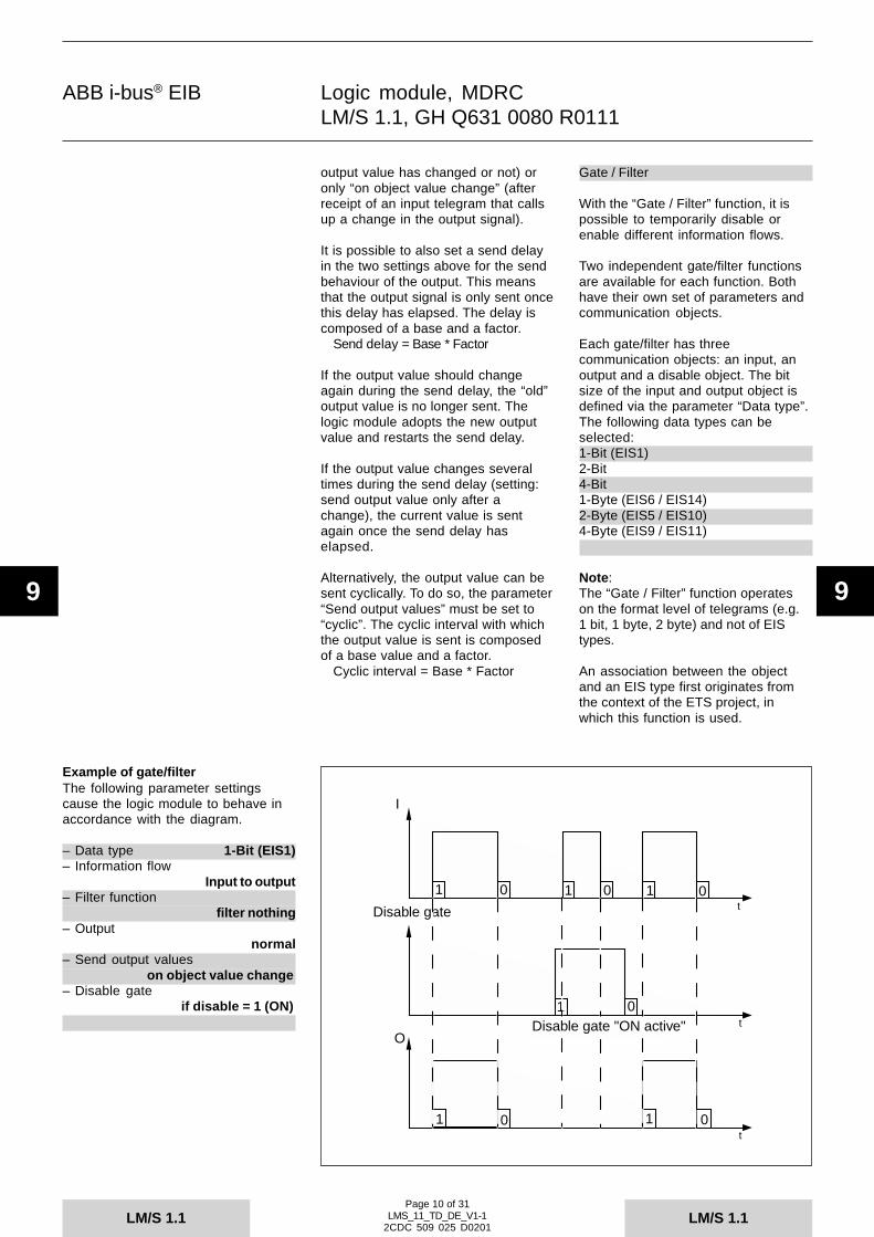
ABB i-bus® EIB
LM/S 1.1LM/S 1.1
9 9
Logic module, MDRCLM/S 1.1, GH Q631 0080 R0111
Page 10 of 31LMS_11_TD_DE_V1-1
2CDC 509 025 D0201
I
t
t
Ot
Disable gate
1 0 0 0
0
1 1
1
1 10 0
Disable gate "ON active"
output value has changed or not) oronly “on object value change” (afterreceipt of an input telegram that callsup a change in the output signal).
It is possible to also set a send delayin the two settings above for the sendbehaviour of the output. This meansthat the output signal is only sent oncethis delay has elapsed. The delay iscomposed of a base and a factor.
Send delay = Base * Factor
If the output value should changeagain during the send delay, the “old”output value is no longer sent. Thelogic module adopts the new outputvalue and restarts the send delay.
If the output value changes severaltimes during the send delay (setting:send output value only after achange), the current value is sentagain once the send delay haselapsed.
Alternatively, the output value can besent cyclically. To do so, the parameter“Send output values” must be set to“cyclic”. The cyclic interval with whichthe output value is sent is composedof a base value and a factor.
Cyclic interval = Base * Factor
Gate / Filter
With the “Gate / Filter” function, it ispossible to temporarily disable orenable different information flows.
Two independent gate/filter functionsare available for each function. Bothhave their own set of parameters andcommunication objects.
Each gate/filter has threecommunication objects: an input, anoutput and a disable object. The bitsize of the input and output object isdefined via the parameter “Data type”.The following data types can beselected:1-Bit (EIS1)2-Bit4-Bit1-Byte (EIS6 / EIS14)2-Byte (EIS5 / EIS10)4-Byte (EIS9 / EIS11)
Note:The “Gate / Filter” function operateson the format level of telegrams (e.g.1 bit, 1 byte, 2 byte) and not of EIStypes.
An association between the objectand an EIS type first originates fromthe context of the ETS project, inwhich this function is used.
Example of gate/filterThe following parameter settingscause the logic module to behave inaccordance with the diagram.
– Data type 1-Bit (EIS1)– Information flow
Input to output– Filter function
filter nothing– Output
normal– Send output values
on object value change– Disable gate
if disable = 1 (ON)

ABB i-bus® EIB
LM/S 1.1LM/S 1.1
9 9
Logic module, MDRCLM/S 1.1, GH Q631 0080 R0111
Page 11 of 31LMS_11_TD_DE_V1-1
2CDC 509 025 D0201
I/O
Disable gate t
t
1 0 1 1 0
1 0Disable gate "ON active"
1
t tt
The size of the disable object isalways 1 bit. The disable object isinactive in the default setting. Theobject is isolated via the parameter“Disable gate”. The same parameterenables an ON or OFF telegram at thedisable object to recall a disablefunction.When the disable function is active,incoming telegrams at the input andoutput objects are not stored. Thismeans that the last value present atthe input and output object before thedisable period is still active once thedisable function has been cancelled.
The setting “Information flow”determines whether the telegrams(information) are routed from “Input tooutput”, from “Output to input“ or in“Both directions”.
If the data type of the input and outputis defined as 1 bit, there are twoadditional parameters. It is possible tofilter out ON or OFF telegrams withthese parameters. The setting “Filterfunction” is used for this purpose. Theoutput signal can also be inverted viathe “Output” parameter.
Staircase light
Two staircase light functions can beset for each function. There are two1 bit communication objects for each.
The staircase light timer is triggeredvia the 1 bit communication object“Staircase light ... input” on receipt ofan ON telegram. Once the period haselapsed, an OFF telegram is sent viathe same object.
The 1 bit communication object“Staircase light ... Disable” is used totemporarily disable the staircase lightfunction. The function is disabled if anON telegram is sent to the objectwhile an OFF telegram enables thefunction again.
If e.g. an ON telegram is received atthe input object during the disableperiod, it is evaluated once thefunction has been enabled again. Assoon as an OFF telegram is receivedat the disable object, the set delayperiod starts to elapse.
The staircase light delay is set using abase and factor via the correspondingparameters.
Delay = Base * Factor
If another ON telegram is received atthe input communication object duringthe staircase light period, the delayrestarts again by default. If thisbehaviour should be prevented, theparameter “Staircase light is” must beset to “not retriggerable”.
Multiplier
The “Multiplier” function is used togenerate several 1 bit and 1 byteinformation elements from 1 bit data.The “Multiplier” function has a 1 bit“Multiplier input” communicationobject and up to four 1 bit “Multiplieroutput”communication objects as wellas up to four further 1 byte “Multiplieroutput” communication objects.
Example of staircase lightThe following parameter settingscause the logic module to behave inaccordance with the diagram.
– Delay Base: 1 min– Factor for delay (1…255)
5– Staircase light is
retriggerable

ABB i-bus® EIB
LM/S 1.1LM/S 1.1
9 9
Logic module, MDRCLM/S 1.1, GH Q631 0080 R0111
Page 12 of 31LMS_11_TD_DE_V1-1
2CDC 509 025 D0201
Input (1-Bit)
Output 1 (1-Bit)
Output 2 (1-Bit)
Output 3 (1-Bit)
Output 4 (1-Bit)
Output 5 (1-Byte)
Output 6 (1-Byte)
ON
ON
ON
OFF
- - -
80
196
Input (1-Bit)
Output 1 (1-Bit)
Output 2 (1-Bit)
Output 3 (1-Bit)
Output 4 (1-Bit)
Output 5 (1-Byte)
Output 6 (1-Byte)
OFF
OFF
- - -
- - -
ON
- - -
- - -
The 1 bit output objects are alwaysavailable. If the 1 byte output objectsshould also be used, they mustpreviously be isolated with the setting“used” via the parameter “Output ...”.Only then are the 1 byte outputobjects visible in ETS.
Telegrams are triggered at the outputcommunication objects once atelegram has been received at theinput communication object. This canbe either an ON or OFF telegram.
It is set separately for each 1 bit outputobject via the parameter “Reaction ofoutput ...” whether an ON or OFFtelegram triggers a telegram at therespective output. The followingoptions are available for selection:– like input telegram– like input telegram inverted– send ON if ON received– send OFF if ON received– send OFF if OFF received– send ON if OFF received
The isolated 1 byte output objectssend predefined values in the event ofan ON or OFF telegram at the inputobject. A common setting is made forall the 1 byte outputs (max. 4) with thesetting “Reaction of the 1-Byteoutputs” as to whether they shouldsend a value after an ON or OFFtelegram at the input.
The value that should be sent isdefined individually for each outputwith the parameter “Value”. The valuecan lie between 0 and 255.
Example of multiplierThe following parameter settingscause the logic module to behave inaccordance with the diagram.
– Reaction of output 1like input telegram
– Reaction of output 2send ON if ON received
– Reaction of output 3send OFF if ON received
– Reaction of output 4send ON if OFF received
– Reaction of the 1-Byte outputsSend value on ON telegrams
– Output 5 used– Value 80– Output 6 used– Value 196– Output 7 not used– Output 8 not used

ABB i-bus® EIB
LM/S 1.1LM/S 1.1
9 9
Logic module, MDRCLM/S 1.1, GH Q631 0080 R0111
Page 13 of 31LMS_11_TD_DE_V1-1
2CDC 509 025 D0201
1
100 %
t
t
100 %
t
Input
Output: Toggle on ON Telegrams
Output: Toggle on OFF Telegrams
100 %
t
Output: Toggle on any telegram receipt
25 %
25 %
25 %
Toggle value
With the “Toggle value” function, it ispossible to switch back and forthbetween two setpoint values. Thefunction has five communicationobjects.
The setpoint values are sent via thecommunication object “Toggle valueoutput”. The object can adopt thefollowing data types:1-Byte Value in % (EIS6)1-Byte Orientation in degrees (EIS6)1-Byte Counter + (EIS14)1-Byte Counter +/- (EIS14)2-Byte Counter + (EIS10)2-Byte Floating point value (EIS5)2-Byte Counter +/- (EIS10)4-Byte Counter + (EIS11)4-Byte Floating point value (EIS9)4-Byte Counter +/- (EIS11)
The different data types are defined,and thereby the setpoint value sizes,via the setting “Output data type”.Setpoints 1 and 2 must be entered inthe corresponding parameters.
The 1 bit object “Toggle value input” isused as an input communicationobject. If a telegram is received at thisobject, the output communicationobject sends the first or secondsetpoint value. There is therebytoggling between the first and secondsetpoint after each telegram at theinput. This means that if setpoint 1 wassent last, setpoint 2 is sent with thesubsequent telegram. If setpoint 2 wassent last, setpoint 1 is sent with thenext telegram.
The parameter “Toggle on”determines whether an ON telegram,an OFF telegram or every telegramcauses a change in the setpoint value.Alternatively, it can be defined withthis parameter that an ON telegram atthe input triggers setpoint 1 and anOFF telegram triggers setpoint 2.
The setpoint value that is currentlyactive can be read out via the 1 bitcommunication object “Toggle valuesetpoint status”. If the object sends thevalue “0” then setpoint 1 is activewhile setpoint 2 is active if value “1” issent.
Example of Toggle valueThe following parameter settingscause the logic module to behave inaccordance with the diagram.
– Output data type1-Byte Value in %
– Setpoint value 125 %
– Setpoint value 2100 %
Three different output reactions areshown in the diagram. The title of thediagram “Output: Toggle on...” is basedon the parameter– Toggle on (see diagram)

ABB i-bus® EIB
LM/S 1.1LM/S 1.1
9 9
Logic module, MDRCLM/S 1.1, GH Q631 0080 R0111
Page 14 of 31LMS_11_TD_DE_V1-1
2CDC 509 025 D0201
To enable the end user to define hisown setpoint, the 1 bit communicationobject “Toggle value save setpoints” isavailable. An ON telegram activatesthe save process while an OFFtelegram deactivates it.
The 1 bit communication object“Toggle value Reset to preset” makesit possible to return to the originalsettings in the parameters. An ONtelegram resets both setpoints to theirorigingal values.
It is possible to also set a send delayfor the send behaviour of the output.This means that the output signal isonly sent once this delay has elapsed.The delay is composed of a base anda factor.
Send delay = Base * Factor
Counter
Each function of the logic module cancount telegrams with the “Counter”function. Depending on the parameter“Data type of the counter”, this can bethe following data types:1-Byte (0…+255)1-Byte (-128…+127)2-Byte (0…+65.535)2-Byte (-32.768…+32.767)4-Byte (0…+4.294.967.295)4-Byte (-2.147.483.648…
+2.147.483.647)
There are eight communicationobjects available for the “Counter”function. Two 1 bit communicationobjects are used to either countupwards or downwards by a step(“Counter up”, “Counter down”).
Via the 1 bit communication object“Counter disable”, it is possible totemporarily deactivate the counter.The disable function is switched on assoon as an ON telegram is received atthe object. An OFF telegram switchesthe disable function off again.
The communication object “Countervalue” sends the current countercontent. The object size depends onthe data type used (parameter: “Datatype of the counter”).
The current counter content can berequested with the 1 bitcommunication object “Counterrequest values”. An ON telegramsimply needs to be sent to the object.The communication object “Countervalue” then sends the information.
The parameters “Count up input” and“Count down input” define whether thecounter counts upwards ordownwards with an ON telegram, OFFtelegram or any telegram.
If there is an overflow of the countervalue i.e. it reaches the end of thecounting range,the counter can“revolve”, “stop” or be “reset to 0”. Theparameter “Reaction on counteroverflow” must be noted for thecorrecting mode of operation (revolve:the counter is set to the minimumvalue e.g. -128 or the maximumvalue).
The counter has an additional counteravailable regardless of the “Data typeof the counter”. The additional counteris always 2 bytes. The current value ofthe additional counter is sent via the2 byte communication object “Counteradd. counter value”.
The additional counter also has the 1bit communication objects “Counteradd. counter overflow” and “Counterreset add. counter”.

ABB i-bus® EIB
LM/S 1.1LM/S 1.1
9 9
Logic module, MDRCLM/S 1.1, GH Q631 0080 R0111
Page 15 of 31LMS_11_TD_DE_V1-1
2CDC 509 025 D0201
The “Counter add. counter overflow”object sends an ON telegram in theevent of an overflow. The additionalcounter can revert to its preset valuevia the “Counter reset add. counter”object. This value is defined with theparameter “Preset value for over/underflow”.
This value can be changedindependently by the user. To do so,the setting “Preset value can beoverwritten” must be set to “yes”. If anON telegram is now received at the“Counter reset add. counter” object,the additional counter adopts thecurrent value as the preset value.
Bus voltage failure/recovery
In the event of a bus voltage failure,the current counter values are not lost.They are written by the RAM into theEEPROM when the bus voltage fails.
On bus voltage recovery, the countervalue can be sent automatically. To doso, the corresponding parameter“Send counter values on bus voltagerecovery” must be set to “Yes”.
Time delay
ON and OFF delays are implementedwith the “Time delay” function. Fourindependent time delays can be setfor each function. They all have theirown set of parameters andcommunication objects.
The time delay function has threecommunication objects: an input, anoutput and a disable object.
The size of the input and output objectdepends on the setting in theparameter “Time delay .... - data type”.This can be one of the following datatypes:1-Bit (EIS1)2-Bit4-Bit1-Byte (EIS6 / EIS14)2-Byte (EIS5 / EIS10)4-Byte (EIS9 / EIS11)
The 1 bit disable object enables thefunction to be deactivated via an ONtelegram. An OFF telegram reactivatesthe function.
When the function is disabled, thereceived telegrams are not evaluated.
The delay periods are defined with abase and a factor.
Delay = Base * Factor
If “1-Bit” is selected as the data type, itis possible to implement an “ONdelay”, an “OFF delay” and an “ONand OFF delay” via the parameter“Function”. The delay periods aredefined with a base and a factor. If e.g.the setting “ON and OFF delay” isselected, the same times apply for theON and OFF delay. For all other datatypes, the time delay acts as atelegram delay. This means that whena telegram is received at the input, thedelay period is started and thetelegram is only sent to the outputonce the period has elapsed. If afurther telegram with a different valueis received during the delay, this newvalue is sent at the end of the delayperiod.
Depending on the parameter “Timedelay is”, the ON or OFF delay is“retriggerable” or “not retriggerable”. Ifthe function can be retriggered, itmeans that an input telegram duringan active delay period restarts thedelay.

ABB i-bus® EIB
LM/S 1.1LM/S 1.1
9 9
Logic module, MDRCLM/S 1.1, GH Q631 0080 R0111
Page 16 of 31LMS_11_TD_DE_V1-1
2CDC 509 025 D0201
Communication objectsFormat converter
2x1 Bit --> 2 Bitfor function A, B and C.- Formatwandler
Communication objectsFormat converter
8x1 Bit --> 1 Byte
Communication objectsFormat converter
1 Byte --> 2 Byte
No. Type Object name Function0 1 bit A: Format converter Receive telegram
input Bit 11 1 bit A: Format converter Receive telegram
input Bit 28 2 bit A: Format converter Send telegram
output 2-Bit16 1 bit B: Format converter Receive telegram
input Bit 117 1 bit B: Format converter Receive telegram
input Bit 224 2 bit B: Format converter Send telegram
output 2-Bit32 1 bit C: Format converter Receive telegram
input Bit 133 1 bit C: Format converter Receive telegram
input Bit 240 2 bit C: Format converter Send telegram
output 2-Bit
No. Type Object name Function0 1 bit A: Format converter Receive telegram
input Bit 11 1 bit A: Format converter Receive telegram
input Bit 22 1 bit A: Format converter Receive telegram
input Bit 33 1 bit A: Format converter Receive telegram
input Bit 44 1 bit A: Format converter Receive telegram
input Bit 55 1 bit A: Format converter Receive telegram
input Bit 66 1 bit A: Format converter Receive telegram
input Bit 77 1 bit A: Format converter Receive telegram
input Bit 88 1 byte A: Format converter Send telegram
output Byte
No. Type Object name Function0 1 byte A: Format converter Receive telegram
input Byte8 2 byte A: Format converter Send telegram
output 2-Byte
Note:For improved clarity, only thecommunication objects for function Aare listed in the following section. Thefunctions B and C have the samecommunication objects when theyhave the appropriate parametersettings.

ABB i-bus® EIB
LM/S 1.1LM/S 1.1
9 9
Logic module, MDRCLM/S 1.1, GH Q631 0080 R0111
Page 17 of 31LMS_11_TD_DE_V1-1
2CDC 509 025 D0201
No. Type Object name Function0 1 byte A: Format converter Receive telegram
input Low Byte1 1 byte A: Format converter Receive telegram
input High Byte8 2 byte A: Format converter Send telegram
output 2-Byte
No. Type Object name Function0 2 byte A: Format converter Receive telegram
input 2-Byte #11 2 byte A: Format converter Receive telegram
input 2-Byte #28 4 byte A: Format converter Send telegram
output 4-Byte
No. Type Object name Function0 2 bit A: Format converter Receive telegram
input 2-Bit8 1 bit A: Format converter Send telegram
output 1-Bit 19 1 bit A: Format converter Send telegram
output 1-Bit 2
No. Type Object name Function0 1 byte A: Format converter Receive telegram
input Byte8 1 bit A: Format converter Send telegram
output Bit 19 1 bit A: Format converter Send telegram
output Bit 210 1 bit A: Format converter Send telegram
output Bit 311 1 bit A: Format converter Send telegram
output Bit 412 1 bit A: Format converter Send telegram
output Bit 513 1 bit A: Format converter Send telegram
output Bit 614 1 bit A: Format converter Send telegram
output Bit 715 1 bit A: Format converter Send telegram
output Bit 8
No. Type Object name Function0 2 byte A: Format converter Receive telegram
input 2-Byte8 1 byte A: Format converter Send telegram
output Low Byte9 1 byte A: Format converter Send telegram
output High Byte
No. Type Object name Function0 4 byte A: Format converter Receive telegram
input 4-Byte8 2 byte A: Format converter Send telegram
output 2-Byte #19 2 byte A: Format converter Send telegram
output 2-Byte #2
Communication objectsFormat converter
2x1 Byte --> 2 Byte
Communication objectsFormat converter
2x2 Byte --> 4 Byte
Communication objectsFormat converter
2 Bit --> 2x1 Bit
Communication objectsFormat converter
1 Byte --> 8x1 Bit
Communication objectsFormat converter
2 Byte --> 2x1 Byte
Communication objectsFormat converter
4 Byte --> 2x2 Byte

ABB i-bus® EIB
LM/S 1.1LM/S 1.1
9 9
Logic module, MDRCLM/S 1.1, GH Q631 0080 R0111
Page 18 of 31LMS_11_TD_DE_V1-1
2CDC 509 025 D0201
No. Type Object name Function0 1 bit A: Logic input 1 Receive telegram1 1 bit A: Logic input 2 Receive telegram2 1 bit A: Logic input 3 Receive telegram3 1 bit A: Logic input 4 Receive telegram4 1 bit A: Logic input 5 Receive telegram5 1 bit A: Logic input 6 Receive telegram6 1 bit A: Logic input 7 Receive telegram7 1 bit A: Logic input 8 Receive telegram8 1 bit A: Logic output Send telegram
Communication objectsLogic- Logikgatter
No. Type Object name Function0 1 byte A: MinMax input 1 Receive telegram1 1 byte A: MinMax input 2 Receive telegram2 1 byte A: MinMax input 3 Receive telegram3 1 byte A: MinMax input 4 Receive telegram4 1 byte A: MinMax output Send telegram
No. Type Object name Function0 2 byte A: MinMax input 1 Receive telegram1 2 byte A: MinMax input 2 Receive telegram2 2 byte A: MinMax input 3 Receive telegram3 2 byte A: MinMax input 4 Receive telegram4 2 byte A: MinMax output Send telegram
No. Type Object name Function0 4 byte A: MinMax input 1 Receive telegram1 4 byte A: MinMax input 2 Receive telegram2 4 byte A: MinMax input 3 Receive telegram3 4 byte A: MinMax input 4 Receive telegram4 4 byte A: MinMax output Send telegram
Communication objectsMin./Max. Value indication
1 byte- Min-/Maxwertgeber
Communication objectsMin./Max. Value indication
2 byte
Communication objectsMin./Max. Value indication
4 byte
No. Type Object name Function0 1 byte A: Threshold value input 1 Receive telegram1 1 bit A: Threshold value T. value 1 Send telegram2 1 byte A: Threshold value input 2 Receive telegram3 1 bit A: Threshold value T. value 2 Send telegram
No. Type Object name Function0 2 byte A: Threshold value input 1 Receive telegram1 1 bit A: Threshold value T. value 1 Send telegram2 2 byte A: Threshold value input 2 Receive telegram3 1 bit A: Threshold value T. value 2 Send telegram
No. Type Object name Function0 4 byte A: Threshold value input 1 Receive telegram1 1 bit A: Threshold value T. value 1 Send telegram2 4 byte A: Threshold value input 2 Receive telegram3 1 bit A: Threshold value T. value 2 Send telegram
Communication objectsThreshold values
1 byte- Schwellwerte
Communication objectsThreshold values
2 byte
Communication objectsThreshold values
4 byte

ABB i-bus® EIB
LM/S 1.1LM/S 1.1
9 9
Logic module, MDRCLM/S 1.1, GH Q631 0080 R0111
Page 19 of 31LMS_11_TD_DE_V1-1
2CDC 509 025 D0201
No. Type Object name Function0 1 bit A: Scene output 1 Send telegram1 1 bit A: Scene output 2 Send telegram2 1 bit A: Scene output 3 Send telegram3 1 bit A: Scene output 4 Send telegram4 1 bit A: Scene output 5 Send telegram5 1 bit A: Scene output 6 Send telegram6 1 bit A: Scene call S1S2 OFF = Sc 1, ON = Sc 27 1 bit A: Scene call S3S4 OFF = Sc 3, ON = Sc 48 1 bit A: Scene call S5S6 OFF = Sc 5, ON = Sc 69 1 bit A: Scene call S7S8 OFF = Sc 7, ON = Sc 8
10 1 bit A: Scene Programming mode on/offProgramming mode
11 1 bit A: Scene Scene was storedSave indication
12 1 bit A: Scene Reset to Receive telegrampreset
Communication objectsScenesHere: 1 bit- Szenen
No. Type Object name Function0 2 byte A: T. Comparator input 1 Input1 2 byte A: T. Comparator input 2 Input2 1 bit A: T. Comparator output Output
No. Type Object name Function0 2 byte A: T. Comparator input 1 Input1 2 byte A: T. Comparator input 2 Input2 1 byte A: T. Comparator output Output
No. Type Object name Function0 2 byte A: T. Comparator input 1 Input1 2 byte A: T. Comparator input 2 Input2 2 byte A: T. Comparator output Output
Communication objectsTemperature comparator
1 bit output- Temperaturvergleicher
Communication objectsTemperature comparator
1 byte output
Communication objectsTemperature comparator
2 byte output
No. Type Object name Function0 1 bit A: Gate 1 input Receive telegram1 1 bit A: Gate 1 disable Receive telegram2 1 bit A: Gate 1 output Send telegram3 1 bit A: Gate 2 input Receive telegram4 1 bit A: Gate 2 disable Receive telegram5 1 bit A: Gate 2 output Send telegram
Communication objectsGate / FilterHere: 1 bit- Tor/Filter
No. Type Object name Function0 1 bit A: Staircase light 1 Send/receive telegram
input1 1 bit A: Staircase light 1 Receive telegram
disable2 1 bit A: Staircase light 2 Send/receive telegram
input3 1 bit A: Staircase light 2 Receive telegram
disable
Communication objectsStaircase light- Treppenlicht

ABB i-bus® EIB
LM/S 1.1LM/S 1.1
9 9
Logic module, MDRCLM/S 1.1, GH Q631 0080 R0111
Page 20 of 31LMS_11_TD_DE_V1-1
2CDC 509 025 D0201
No. Type Object name Function0 1 bit A: Multiplier Receive telegram
input1 1 bit A: Multiplier Send telegram
output 12 1 bit A: Multiplier Send telegram
output 23 1 bit A: Multiplier Send telegram
output 34 1 bit A: Multiplier Send telegram
output 45 1 byte A: Multiplier Send telegram
output 56 1 byte A: Multiplier Send telegram
output 67 1 byte A: Multiplier Send telegram
output 78 1 byte A: Multiplier Send telegram
output 8
Communication objectsMultiplier- Vervielfacher
No. Type Object name Function0 1 bit A: Toggle value Receive telegram
input3 1 bit A: Toggle value Receive telegram
save setpoints4 1 bit A: Toggle value Receive telegram
Reset to preset5 1 byte A: Toggle value Send telegram
output6 1 bit A: Toggle value Send telegram
setpoint status
Communication objectsToggle ValueHere: 1 byte output- Wert umschalten
No. Type Object name Function0 1 bit A: Counter up Receive telegram1 1 bit A: Counter down Receive telegram2 1 bit A: Counter disable Receive telegram3 1 bit A: Counter Receive telegram
request values4 1 byte A: Counter value Send telegram5 2 byte A: Counter Send telegram
add. counter value6 1 bit A: Counter Send telegram
add. counter overflow7 1 bit A: Counter reset Receive telegram
add. counter
Communication objectsCounterHere: 1 byte output- Zähler
No. Type Object name Function0 1 bit A: Time delay 1 input Receive telegram1 1 bit A: Time delay 1 disable Receive telegram2 1 bit A: Time delay 1 output Send telegram3 1 bit A: Time delay 2 input Receive telegram4 1 bit A: Time delay 2 disable Receive telegram5 1 bit A: Time delay 2 output Send telegram6 1 bit A: Time delay 3 input Receive telegram7 1 bit A: Time delay 3 disable Receive telegram8 1 bit A: Time delay 3 output Send telegram9 1 bit A: Time delay 4 input Receive telegram
10 1 bit A: Time delay 4 disable Receive telegram11 1 bit A: Time delay 4 output Send telegram
Communication objectsTime delayHere: 1 bit- Zeitglied

ABB i-bus® EIB
LM/S 1.1LM/S 1.1
9 9
Logic module, MDRCLM/S 1.1, GH Q631 0080 R0111
Page 21 of 31LMS_11_TD_DE_V1-1
2CDC 509 025 D0201
ParametersThe default setting for the values isprinted in bold type.- Allgemein
Parameterswith Format converter function.
The default setting for the values isprinted in bold type.- Formatwandler
General:Separate for each function:– Function … not used
Format converterLogicMin./Max. Value indicationThreshold valuesScenesTemperature comparatorGate / FilterStaircase lightMultiplierToggle ValueCounterTime delay
Format converter:… - Format converter:– Converter Function 2x1-Bit --> 1x2-Bit
8x1-Bit --> 1-Byte1x1-Byte --> 2-Byte2x1-Byte --> 2-Byte2x2-Byte --> 4-Byte1x2-Bit --> 2x1-Bit1-Byte --> 8x1-Bit2-Byte --> 2x1-Byte4-Byte --> 2x2-Byte
Only for 1x1-Byte --> 2-Byte:--> Note: High byte of the output = 0Low byte of the output = input byte
– Read input values over EIB Yes / Noafter bus voltage recovery
– Send output values on reception of new telegramon object value change

ABB i-bus® EIB
LM/S 1.1LM/S 1.1
9 9
Logic module, MDRCLM/S 1.1, GH Q631 0080 R0111
Page 22 of 31LMS_11_TD_DE_V1-1
2CDC 509 025 D0201
Logic:… - Logic Inp. 1-4:– Logical operation AND
ORExclusive ORNANDNOREquivalence
Separate for each input:– Input… not used
normalinverted
Only when input is used:– Object value after bus voltage read values over EIB
recovery use value before bus voltage failuse 0 as presetuse 1 as preset
… - Logic Inp. 5-8:Separate for each input:– Input … not used
normalinverted
Only when input is used:– Object value after bus voltage read values over EIB
recovery use value before bus voltage failuse 0 as presetuse 1 as preset
… - Logic output:– Output normal
inverted– Send output values on reception of new telegram
on object value changecyclic
Only if cyclical sending is selected:– Send delay none
Base: 100 msBase: 1 sBase: 10 sBase: 1 minBase: 10 minBase: 1 h
Only if send delay is selected:– Send delay factor 1 (1…255)
Only if cyclical sending is selected:– Cyclic sending base 1 s / 10 s / 1 min / 10 min / 1 h– Cyclic sending factor 1
Parameterwith Logic function.
The default setting for the values isprinted in bold type.- Logikgatter

ABB i-bus® EIB
LM/S 1.1LM/S 1.1
9 9
Logic module, MDRCLM/S 1.1, GH Q631 0080 R0111
Page 23 of 31LMS_11_TD_DE_V1-1
2CDC 509 025 D0201
Min./Max. Value indication:… - Min./Max. Value indication:– Data type of the inputs 1-Byte Value in % [0…100%] (EIS6)
1-Byte Orientation in degrees[0…360](EIS6)1-Byte Counter [0…+255] (EIS14)1-Byte Counter [-128…+127] (EIS14)2-Byte Counter [0…+65.535] (EIS10)2-Byte Floating point value (EIS5)2-Byte Counter [-32.768…+32.767](EIS10)4-Byte Floating point value (EIS9)4-Byte Counter[-10.000.000…+10.000.000] (EIS11)
Separate for each input:– Input … not used
used– Output takes the highest value
takes the lowest valuetakes the average value
– Send output values on reception of new telegramon object value changecyclic
Only if cyclical sending is selected:– Cyclic sending base 1 s / 10 s / 1 min / 10 min / 1 h– Cyclic sending factor 1
Parameterswith Min./Max. Value indicationfunction.
The default setting for the values isprinted in bold type.- Min-/Maxwertgeber

ABB i-bus® EIB
LM/S 1.1LM/S 1.1
9 9
Logic module, MDRCLM/S 1.1, GH Q631 0080 R0111
Page 24 of 31LMS_11_TD_DE_V1-1
2CDC 509 025 D0201
Threshold values:Separate for each threshold:… - Threshold value …:– Data type of the input 1-Byte Value in % [0…100%] (EIS6)
1-Byte Orientation in degrees[0…360](EIS6)1-Byte Counter [0…+255] (EIS14)1-Byte Counter [-128…+127] (EIS14)2-Byte Counter [0…+65.535] (EIS10)2-Byte Floating point value (EIS5)2-Byte Counter [-32.768…+32.767](EIS10)4-Byte Floating point value (EIS9)4-Byte Counter[-10.000.000…+10.000.000] (EIS11)
Only for “1-Byte Value in %”:– Threshold value [25=10%, 255 =10%] 0Only for “1-Byte Orientation in degrees”:– Threshold value [255 = 360°] 0Only for “4-Byte Counter”:– Threshold value (+/-1.000.000.000) 0For all other data types:– Threshold value 0– Bandwidth of the hysteresis 0
in % of the threshold value [0…50%]– Send threshold object if object value is out of bandwidth
of hysteresison object value change
– If value is above the upper border OFF telegramof hysteresis send ON telegram
no telegram– If value is below the lower border OFF telegram
of hysteresis send ON telegramno telegram
– Send delay noneBase: 100 msBase: 1 sBase: 10 sBase: 1 minBase: 10 minBase: 1 h
Only if send delay is selected:– Send delay factor 1 (1…255)
Parameterswith Threshold values function.
The default setting for the values isprinted in bold type.- Schwellwerte

ABB i-bus® EIB
LM/S 1.1LM/S 1.1
9 9
Logic module, MDRCLM/S 1.1, GH Q631 0080 R0111
Page 25 of 31LMS_11_TD_DE_V1-1
2CDC 509 025 D0201
Scenes:… - Scenes Common– Use scenes 1/2 Yes / No– Use scenes 3/4 Yes / No– Use scenes 5/6 Yes / No– Use scenes 7/8 Yes / No– Reset object is not used
used
… - Output types:Separate for each output:– Data type of output … 1-Bit Value (EIS1)
1-Byte Value in % [0…100%] (EIS6)1-Byte Value [0…255]2-Byte Temperature value (EIS5)
Separate for each scene:… - Scene …:Separate for each output:Only for “1 Bit Value”:– Preset output … OFF
ONno reaction
Only for “1-Byte Value in %”:– Preset output … no reaction
0 %10 %…90 %100 %
Only for “1-Byte Value”:– Preset output … 1Only for “2-Byte Temperature value”:– Preset output … 1
– Delay between sending the noneoutput telegrams Base: 100 ms
Base: 1 sBase: 10 sBase: 1 minBase: 10 minBase: 1 h
Only if delay is selected:– Factor [1…255] 1
Parameterswith Scenes function.
The default setting for the values isprinted in bold type.- Szenen
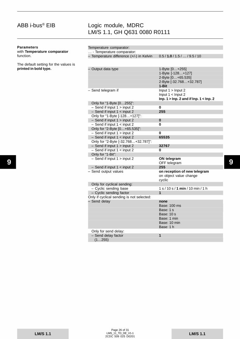
ABB i-bus® EIB
LM/S 1.1LM/S 1.1
9 9
Logic module, MDRCLM/S 1.1, GH Q631 0080 R0111
Page 26 of 31LMS_11_TD_DE_V1-1
2CDC 509 025 D0201
Temperature comparator:… - Temperature comparator:– Temperature difference (+/-) in Kelvin 0.5 / 1.0 / 1.5 / … / 9.5 / 10
– Output data type 1-Byte [0…+255]1-Byte [-128…+127]2-Byte [0…+65.535]2-Byte [-32.768…+32.787]1-Bit
– Send telegram if Input 1 > Input 2Input 1 < Input 2Inp. 1 > Inp. 2 and if Inp. 1 < Inp. 2
Only for “1-Byte [0…255]”:– Send if input 1 > input 2 0– Send if input 1 < input 2 255Only for “1-Byte [-128…+127]”:– Send if input 1 > input 2 0– Send if input 1 < input 2 0Only for “2-Byte [0…+65.535]”:– Send if input 1 > input 2 0– Send if input 1 < input 2 65535Only for “2-Byte [-32.768…+32.787]”:– Send if input 1 > input 2 32767– Send if input 1 < input 2 0Only for “1-Bit”:– Send if input 1 > input 2 ON telegram
OFF telegram– Send if input 1 < input 2 255
– Send output values on reception of new telegramon object value changecyclic
Only for cyclical sending:– Cyclic sending base 1 s / 10 s / 1 min / 10 min / 1 h– Cyclic sending factor 1
Only if cyclical sending is not selected:– Send delay none
Base: 100 msBase: 1 sBase: 10 sBase: 1 minBase: 10 minBase: 1 h
Only for send delay:– Send delay factor 1 (1…255)
Parameterswith Temperature comparatorfunction.
The default setting for the values isprinted in bold type.- Temperaturvergleicher

ABB i-bus® EIB
LM/S 1.1LM/S 1.1
9 9
Logic module, MDRCLM/S 1.1, GH Q631 0080 R0111
Page 27 of 31LMS_11_TD_DE_V1-1
2CDC 509 025 D0201
Gate / Filter:Separate for each gate/filter:… - Gate/Filter …:– Data type 1-Bit (EIS1)
2-Bit4-Bit1-Byte (EIS6 / EIS14)2-Byte (EIS5 / EIS10)4-Byte (EIS9 / EIS11)
– Information flow Input to outputOutput to inputBoth directions
Only for “1-Bit”:– Filter function filter nothing
filter ON telegramsfilter OFF telegrams
– Output normalinverted
– Send output values on reception of new telegramon object value change
– Disable gate Noif disable = 1 (ON)if disable = 0 (OFF)
Only if gate is disabled:– Note: During disable the input
value is not saved
Staircase light:… - Staircase light 1+2:Separate for each staircase light:Staircase light …:– Delay Base: 100 ms
Base: 1 sBase: 10 sBase: 1 minBase: 10 minBase: 1 h
– Factor for delay [1…255] 1– Staircase light is retriggerable
not retriggerable
Parameterswith Gate / Filter function.
The default setting for the values isprinted in bold type.- Tor / Filter
Parameterswith Staircase light function.
The default setting for the values isprinted in bold type.- Treppenlicht

ABB i-bus® EIB
LM/S 1.1LM/S 1.1
9 9
Logic module, MDRCLM/S 1.1, GH Q631 0080 R0111
Page 28 of 31LMS_11_TD_DE_V1-1
2CDC 509 025 D0201
Multiplier:… - Multiplier 1-Bit:Separate for outputs 1 to 4:– Reaction of output … like input telegram
like input telegram invertedsend ON if ON receivedsend OFF if ON receivedsend OFF if OFF receivedsend OFF if ON received
… - Multiplier 1-Byte:– Reaction of the 1-Byte outputs Send value on ON telegrams
Send value on OFF telegramsSeparate for outputs 5 to 8:– Output… used
not usedOnly if used:– Value [0…255] 0
Parameterswith Multiplier function.
The default setting for the values isprinted in bold type.- Vervielfacher

ABB i-bus® EIB
LM/S 1.1LM/S 1.1
9 9
Logic module, MDRCLM/S 1.1, GH Q631 0080 R0111
Page 29 of 31LMS_11_TD_DE_V1-1
2CDC 509 025 D0201
Toggle Value:… - Toggle value:– Output data type 1-Byte Value in % (EIS6)
1-Byte Orientation in degrees (EIS6)1-Byte Counter + (EIS14)1-Byte Counter +/- (EIS14)2-Byte Counter + (EIS10)2-Byte Floating point value (EIS5)2-Byte Counter +/- (EIS10)4-Byte Counter + (EIS11)4-Byte Floating point value (EIS9)4-Byte Counter +/- (EIS11)
Only for “1-Byte Value in %”:– Setpoint value 1 [25=10%, 255=100%] 0– Setpoint value 1 is fix
rewritable over EIB– Setpoint value 2 [25=10%, 255=100%] 0– Setpoint value 2 is fix
rewritable over EIBOnly for “1-Byte Orientation in degrees”:– Setpoint value 1 [7=10 Grad, 255=360 Grad] 0– Setpoint value 1 is fix
rewritable over EIB– Setpoint value 2 [7=10 Grad, 255=360 Grad] 0– Setpoint value 2 is fix
rewritable over EIBFor all other data types:– Setpoint value 1 0– Setpoint value 1 is fix
rewritable over EIB– Setpoint value 2 0– Setpoint value 2 is fix
rewritable over EIB
– Toggle on any telegram receiptON telegrams onlyOFF telegrams onlyON telegr. to value 1 /OFF telegr. to value 2
– Send delay noneBase: 100 msBase: 1 sBase: 10 sBase: 1 minBase: 10 minBase: 1 h
Only for send delay:– Send delay factor 1 (1…255)
Parameterswith Toggle Value function.
The default setting for the values isprinted in bold type.- Wert umschalten

ABB i-bus® EIB
LM/S 1.1LM/S 1.1
9 9
Logic module, MDRCLM/S 1.1, GH Q631 0080 R0111
Page 30 of 31LMS_11_TD_DE_V1-1
2CDC 509 025 D0201
Counter:… - Counter:– Data type of the counter 1-Byte [0…+255]
1-Byte [-128…+127]2-Byte [0…+65.535]2-Byte [-32.768…+32.787]4-Byte [0…4.294.967.295]4-Byte [-2.147.483.648…+2.147.483.647]
– Count up input react only on OFF telegramreact only on ON telegramreact on any telegram
– Count down input react only on OFF telegramreact only on ON telegramreact on any telegram
– Reaction on counter overflow revolvestopreset to 0
– Send counter values on bus voltage Yes / Norecovery
– Use additional counter Yes / No– Send cyclic counter values Yes / No
Only for cyclical sending:– Base for cyclic sending 1 s
10 s1 min10 min1 h
– Factor for cyclic sending 1
Only if additional counter is used:– Preset value for over/underflow 0
(-32.768…32.768)– Preset value can be overwritten Yes / No
Parameterswith Counter function.
The default setting for the values isprinted in bold type.- Zähler

ABB i-bus® EIB
LM/S 1.1LM/S 1.1
9 9
Logic module, MDRCLM/S 1.1, GH Q631 0080 R0111
Page 31 of 31LMS_11_TD_DE_V1-1
2CDC 509 025 D0201
Time delay:Separate for each time delay:… - Time delay …:– Time delay … - data type 1-Bit Value (EIS1)
2-Bit Value4-Bit Value1-Byte Value (EIS6) / (EIS14)2-Byte Value (EIS5) / (EIS10)4-Byte Value (EIS9) / (EIS11)
Only for “1-Bit Value” data type:– Function OFF delay
ON delayON and OFF delay
For all other data types:– Function Telegram delay– Base for delay 1 s
10 s1 min10 min1 h
– Factor for delay 1– Time delay is retriggerable
not retriggerable
Parameterswith Time delay function.
The default setting for the values isprinted in bold type.- Zeitglied